WO2012111182A1 - Structure de cheminement de faisceaux de câbles - Google Patents
Structure de cheminement de faisceaux de câbles Download PDFInfo
- Publication number
- WO2012111182A1 WO2012111182A1 PCT/JP2011/064390 JP2011064390W WO2012111182A1 WO 2012111182 A1 WO2012111182 A1 WO 2012111182A1 JP 2011064390 W JP2011064390 W JP 2011064390W WO 2012111182 A1 WO2012111182 A1 WO 2012111182A1
- Authority
- WO
- WIPO (PCT)
- Prior art keywords
- wire harness
- door
- guide
- exterior member
- wiring structure
- Prior art date
- Legal status (The legal status is an assumption and is not a legal conclusion. Google has not performed a legal analysis and makes no representation as to the accuracy of the status listed.)
- Ceased
Links
Images


Classifications
-
- B—PERFORMING OPERATIONS; TRANSPORTING
- B60—VEHICLES IN GENERAL
- B60R—VEHICLES, VEHICLE FITTINGS, OR VEHICLE PARTS, NOT OTHERWISE PROVIDED FOR
- B60R16/00—Electric or fluid circuits specially adapted for vehicles and not otherwise provided for; Arrangement of elements of electric or fluid circuits specially adapted for vehicles and not otherwise provided for
- B60R16/02—Electric or fluid circuits specially adapted for vehicles and not otherwise provided for; Arrangement of elements of electric or fluid circuits specially adapted for vehicles and not otherwise provided for electric constitutive elements
- B60R16/0207—Wire harnesses
- B60R16/0215—Protecting, fastening and routing means therefor
-
- H—ELECTRICITY
- H02—GENERATION; CONVERSION OR DISTRIBUTION OF ELECTRIC POWER
- H02G—INSTALLATION OF ELECTRIC CABLES OR LINES, OR OF COMBINED OPTICAL AND ELECTRIC CABLES OR LINES
- H02G11/00—Arrangements of electric cables or lines between relatively-movable parts
-
- H—ELECTRICITY
- H02—GENERATION; CONVERSION OR DISTRIBUTION OF ELECTRIC POWER
- H02G—INSTALLATION OF ELECTRIC CABLES OR LINES, OR OF COMBINED OPTICAL AND ELECTRIC CABLES OR LINES
- H02G3/00—Installations of electric cables or lines or protective tubing therefor in or on buildings, equivalent structures or vehicles
- H02G3/02—Details
- H02G3/06—Joints for connecting lengths of protective tubing or channels, to each other or to casings, e.g. to distribution boxes; Ensuring electrical continuity in the joint
- H02G3/0616—Joints for connecting tubing to casing
- H02G3/0691—Fixing tubing to casing by auxiliary means co-operating with indentations of the tubing, e.g. with tubing-convolutions
-
- H—ELECTRICITY
- H02—GENERATION; CONVERSION OR DISTRIBUTION OF ELECTRIC POWER
- H02G—INSTALLATION OF ELECTRIC CABLES OR LINES, OR OF COMBINED OPTICAL AND ELECTRIC CABLES OR LINES
- H02G3/00—Installations of electric cables or lines or protective tubing therefor in or on buildings, equivalent structures or vehicles
- H02G3/02—Details
- H02G3/04—Protective tubing or conduits, e.g. cable ladders or cable troughs
- H02G3/0437—Channels
Definitions
- the present invention relates to a technique for routing a wire harness between a vehicle body and a door.
- Patent Document 1 discloses a wiring harness wiring structure between a vehicle body and a door.
- the wire harness that is routed to the door and pulled out to the vehicle body side is inserted into a tube made of hard resin, and the tube is slidably accommodated in a guide portion provided on the door.
- the surplus length portion of the wire harness drawn out from the tube is accommodated in a surplus length absorption space provided in the guide portion.
- the guide portion is adjacent to the linear upper side peripheral wall, the side peripheral wall on the distal end side of the upper side peripheral wall that is arranged with a linear slide space and curved downward, and the side peripheral wall.
- the shallow bottom which has the side wall of the other side of the shape curved.
- This extra length absorbing space is a curved space having a large radius toward the corners of the upper side peripheral wall and the side peripheral wall.
- an object of the present invention is to improve the bending performance by more smoothly absorbing the extra length of the wire harness in the opening / closing operation of the door.
- a 1st aspect is a wire harness wiring structure part which wires a wire harness between a vehicle body and a door, Comprising: It spans between the said vehicle harness and the said door among the said wire harness and the said wire harness.
- a cylindrical or groove-shaped guide portion that can be disposed in the door and can guide the other end portion of the exterior member toward the storage portion.
- a 2nd aspect is a wire harness wiring structure part which concerns on a 1st aspect, Comprising:
- the said accommodating part is a line along the guide direction of the said guide part, and the said wire harness in the side view.
- the wall portion is formed so as to be able to regulate the path so that the extra length is absorbed by bending to a path passing through a line along the extending direction of the portion fixed to the in-door positioning portion.
- a 3rd aspect is a wire harness wiring structure part which concerns on a 1st or 2nd aspect, Comprising:
- the said accommodating part is a line along the guide direction of the said guide part, and the said wire harness.
- the wall portion is formed so as to be able to regulate the path so as to bend into a path passing through a line orthogonal to the guide direction of the guide section and absorb the surplus length.
- a fourth aspect is a wire harness routing structure according to any one of the first to third aspects, wherein the accommodating part is the side of the wire harness in the open state in a side view.
- the wall portion is routed so that an intermediate portion between the other end portion of the exterior member and the positioning portion in the door is accommodated in a path parallel to a direction connecting the other end portion of the exterior member and the positioning portion in the door. It is designed to be regulated.
- a fifth aspect is a wire harness wiring structure part according to any one of the first to fourth aspects, wherein the accommodating part has a second wall and a second wall facing each other with the accommodating space in a side view. And the first wall portion has a linear shape extending in a direction connecting the other end portion of the guide portion and the in-door positioning portion when the door is open in a side view.
- the second wall portion extends in the guide direction of the guide portion in a side view, and is fixed by the in-door positioning portion of the wire harness through a curved portion. It extends along the extending direction of the part.
- a sixth aspect is the wire harness routing structure according to any one of the first to fifth aspects, wherein the exterior member is a flat corrugated tube having higher rigidity than the wire harness, Is bridged between the vehicle body and the door in a flat posture.
- the wire harness wiring structure part which concerns on a 1st aspect, while guiding the exterior member sheathed by the wire harness with the guide part, the wire harness extended from the other end part of the said exterior member by the accommodating part is extra length Since it is formed so that it can be absorbed, the wire harness can be smoothly advanced and retracted into the door as the door is opened and closed to absorb the extra length.
- the housing portion is a wall that can restrict the wire harness from being bent more than a path passing through the line along the guide direction of the guide portion and the line perpendicular to the guide direction through the in-door positioning portion. Therefore, the load applied to the wire harness can be reduced as much as possible, and the extra length of the wire harness can be absorbed more smoothly during the opening and closing operation of the door, thereby improving the bending performance.
- the housing portion is fixed to the in-door positioning portion of the wire harness and the line along the guide direction of the guide portion in a side view. Since the wall portion is formed so as to be able to regulate the path so that the extra length is absorbed by being bent into a path passing through the line along the extending direction of the portion, the load applied to the wire harness can be further reduced.
- the accommodating portion is in a path passing through the line along the guide direction of the guide portion and the line orthogonal to the guide direction of the guide portion in the side view. Since the wall portion is formed so as to be able to regulate the path so as to be bent and absorb the surplus length, the surplus length can be absorbed more greatly while reducing the load applied to the wire harness.
- the housing portion in the side view, in the side view, includes an intermediate portion between the other end portion of the exterior member and the door positioning portion in the wire harness. Since the wall is formed so that the path can be regulated so that it can be accommodated in a path parallel to the direction connecting the other end of the exterior member and the positioning part in the door, the load applied to the wire harness is reduced when the door is open. In addition, the extra length absorption space can be secured larger.
- the accommodating portion is along the direction in which the first wall portion connects the other end portion of the exterior member and the in-door positioning portion when the door is open in a side view.
- the second wall portion extends along the guide direction of the guide portion and is fixed at the in-door positioning portion of the wire harness via the curved portion. It is formed so as to extend along the extending direction. For this reason, the load added to a wire harness at the time of opening and closing of a door can be reduced, ensuring the surplus length absorption space of a wire harness.
- the exterior member is a flat corrugated tube having higher rigidity than the wire harness, and is laid between the vehicle body and the door in a flat posture along the vertical direction. Therefore, it is possible to suppress bending and sagging while allowing bending deformation in the horizontal direction in the entire portion of the wire harness spanned between the vehicle body and the door. Thereby, the wire harness can be more reliably advanced and retracted in the guide portion and the accommodating portion with the opening and closing operation of the door, and the extra length can be absorbed smoothly.
- the wire harness routing structure 10 is for routing the wire harness WH between the vehicle body 2 and the door 6 of the automobile.
- a plurality of electric wires for supplying power to or transmitting signals to electric devices such as a power window, a door lock, a motor for a side mirror, a speaker, and a switch system mounted on the door 6 are arranged in the routing route.
- electric devices such as a power window, a door lock, a motor for a side mirror, a speaker, and a switch system mounted on the door 6 are arranged in the routing route.
- the portion of the wire harness WH that extends from the vehicle body 2 to the door 6 is configured by bundling the plurality of electric wires into one.
- the wire harness WH is branched in the door 6 and connected to the various electric devices.
- the door 6 is connected to the vehicle body 2 via a door hinge 5 and an opening degree restricting portion 3 so as to be able to open and close an entrance / exit formed in the vehicle body 2 (see FIGS. 1 and 3).
- the vehicle body 2 refers to a frame portion formed of a metal member.
- the target door 6 is a front side door, and for convenience of explanation, it is assumed that it is connected to the vehicle body 2 so as to change its posture around an axis along the vertical direction (rotation axis of the door hinge 5). .
- the door 6 will be described with the front-rear direction in the closed position as the front-rear direction of the door 6 regardless of the opening / closing position.
- the opening degree restriction part 3 (also referred to as a door check link) is a member for maintaining the door 6 at a predetermined opening degree, and includes an arm part and a case part.
- the arm portion is formed in a bar shape in which a portion thinner than other portions is formed at a plurality of positions in the longitudinal direction.
- the case portion is formed in a casing shape having a holding portion that is pressed and urged so as to hold the arm portion. Then, the holding portion maintains the posture of the door 6 with the thin portion of the arm portion sandwiched between the half-open posture and the full-open posture of the door 6.
- the door 6 is provided with a waterproof weather strip 6w along its peripheral edge (see FIG. 3).
- the weather strip 6w is a member formed of rubber or the like that can be in close contact with the opening edge of the vehicle body 2 and keep a water-tight state inside and outside the vehicle interior with the door 6 closed.
- FIG. 3 only the weather strip 6 w provided on the door 6 is shown, but a weather strip may also be provided at the opening edge of the entrance / exit of the vehicle body 2. That is, such a weather strip is preferably close to the peripheral edge of the door 6.
- the door 6 includes a door inner panel 7 formed of a metal material, a door outer panel as an exterior member provided outside the vehicle interior, and an interior formed of a resin material and attached to the vehicle interior side of the door inner panel 7. And a trim 8 as a member (see FIG. 3).
- the door 6 is comprised so that the wire harness WH can be inserted in the inside from the front-end part.
- a recessed portion 7h that opens at the front end portion is formed in the front side portion of the door inner panel 7, and the wire harness WH is routed between the door inner panel 7 and the trim 8 from the vehicle body 2 side through the recessed portion 7h. It is like that.
- this recessed part 7h is formed so that the protector P mentioned later can be accommodated.
- the wire harness WH is routed in the vehicle body 2 at a portion of the opening edge of the doorway opened and closed by the door 6 and facing the front opening of the recess 7 h in the closed posture of the door 6.
- a hole 2h is formed (see FIG. 1).
- the recess 7 h and the hole 2 h are formed so as to face each other in the front-rear direction of the vehicle body 2.
- the recess 7h and the hole 2h are hidden by the vehicle body 2 and the door 6 when the door 6 is closed (see FIG. 2).
- the wire harness WH is routed between the vehicle body 2 and the door 6 from the weather strip 6w to the vehicle interior side, the opening on the front side of the recess 7h and the hole 2h are formed from the weather strip 6w. It is formed on the vehicle interior side (see FIG. 2).
- the weather strip 6w is a weather strip that is disposed on the outermost side of the vehicle interior, and the wire harness WH is also located on the vehicle interior side from the weather strip 6w. It only has to be routed. That is, another weather strip may be provided on the vehicle interior side from the wire harness WH routed between the vehicle body 2 and the door 6.
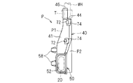
- the wire harness wiring structure unit 10 includes the wire harness WH, the exterior member 20, the attachment member 30, the accommodation unit 40, and the guide unit 50.
- the exterior member 20 is exteriorized in the part including the part spanned between the vehicle body 2 and the door 6 among the wire harness WH (refer FIG. 4).
- the exterior member 20 is a member that protects the wire harness WH from the outside and supports the wire harness WH while suppressing drooping between the vehicle body 2 and the door 6.
- the exterior member 20 is formed in a cylindrical shape, and protects the wire harness WH disposed inside. More specifically, the exterior member 20 has flexibility (entirely in the longitudinal direction) so as to bend between the vehicle body 2 and the door 6 corresponding to the opening / closing operation of the door 6, and at least the wire harness. A member having rigidity higher than WH, preferably high enough to support the wire harness WH while suppressing bending and sagging between the vehicle body 2 and the door 6 is employed.
- the exterior member 20 is a corrugated tube manufactured by extrusion molding and blow molding or vacuum molding of a synthetic resin (for example, PP (polypropylene), PA (polyamide), PE (polyethylene)).
- the corrugated tube is a member in which convex ridges and concave valleys along the circumferential direction are alternately continued in the axial direction. And in the cross-sectional view parallel to the axial direction of the corrugated tube, the inner angle between the top of the peak and the side walls on both sides and the inner angle between the bottom of the valley and the side walls on both sides change in size. It expands and contracts. That is, when a force is applied in the bending direction, the corrugated tube is deformed and bent so that each inner angle of the inner peripheral portion becomes smaller and each inner angle of the outer peripheral portion becomes larger.
- the exterior member 20 is formed in a flat shape (for example, a flat shape such as a substantially elliptical shape or a substantially rectangular shape in cross section).
- a flat shape for example, a flat shape such as a substantially elliptical shape or a substantially rectangular shape in cross section.
- it is formed in a substantially rectangular shape in section view with rounded corners. That is, it is a shape that is difficult to bend in the longitudinal direction (high rigidity) in a cross-sectional view, and is easy to bend in the short direction (high flexibility). More specifically, since the corrugated tube can be expanded and contracted in the axial direction normally at any part in the circumferential direction, the longer the distance between the inner peripheral side end part and the outer peripheral side end part, the smaller the angle change amount and the more difficult it is to bend.
- the wire harness WH may be formed in a circular shape in cross section, or may be formed in a cross sectional shape corresponding to the internal shape of the exterior member 20.
- the exterior member 20 should just have rigidity higher than the wire harness WH, and is not limited to the corrugated tube as mentioned above.
- a flat cylindrical member molded with rubber having relatively high hardness EPDM (ethylene propylene diene rubber), elastomer or the like) can be employed.
- One end of the exterior member 20 is fixed to a portion of the wire harness WH that is routed in the vehicle body 2 by being wound with a tape T or the like and fixed to an attachment member 30 that is attached to the vehicle body 2. (See FIG. 3). Moreover, the other end part of the exterior member 20 is fixed to the wire harness WH by tape T winding or the like, and is movable in the door 6 together with the wire harness WH (see FIGS. 1 and 2).
- the attachment member 30 is a member that attaches one end of the exterior member 20 that is sheathed to the wire harness WH to the vehicle body 2 so as to route the wire harness WH to the vehicle body 2 side (FIGS. 1, 3, and 4). reference).
- the attachment member 30 is fixed to one end side portion of the exterior member 20 and is formed to be attachable to the vehicle body 2. More specifically, the attachment member 30 is configured to be attachable by being pressed against a hole 2 h formed in the vehicle body 2.
- the attachment member 30 includes an insertion portion 34, a pressing portion 36, and a vehicle body side fitting portion 38.
- the insertion portion 34 is formed in a cylindrical shape that can be inserted into the hole 2h of the vehicle body 2 and in which the exterior member 20 can be disposed inside.
- the insertion part 34 is inserted toward the front of the vehicle body 2 (hereinafter, the insertion direction S) with respect to the hole 2h.
- a locking portion 35 that can be locked to the hole 2 h in a state where the insertion portion 34 is inserted into the hole 2 h is provided at the distal end portion of the insertion portion 34.
- the locking portions 35 are formed so as to protrude from the circumferential positions of the insertion portion 34 in the circumferential direction (four locations at equal intervals) to the outer peripheral side, and are respectively forward in the insertion direction S with respect to the peripheral portion of the hole 2h.
- the locking portion 35 has a locking surface that can be contacted from the side. More specifically, the locking portion 35 is formed so that the protruding dimension gradually increases from the distal end side to the proximal end side of the insertion portion 34.
- the insertion portion 34 or the locking portion 35 itself is elastically deformed toward the inner peripheral side of the insertion portion 34, and gets over the hole 2h. It is elastically returned to the outer peripheral side at the position and is locked to the peripheral edge of the hole 2h.
- the pressing portion 36 is provided continuously to the proximal end portion of the insertion portion 34, and is formed in a hook shape projecting to the outer peripheral side.
- the pressing portion 36 can come into surface contact with the peripheral portion of the hole 2h from the rear side in the insertion direction S. That is, the outer peripheral shape of the pressing portion 36 is formed larger than the hole portion 2h.
- the locking part 35 is locked from the front side in the insertion direction S with respect to the peripheral part of the hole 2h, and the presser part 36 is the peripheral part of the hole 2h. Is in surface contact from the rear side in the insertion direction S.
- the peripheral edge of the hole 2 h is sandwiched between the locking portion 35 and the pressing portion 36, and the attachment member 30 is fixed to the vehicle body 2.
- the vehicle body side fitting portion 38 is a portion that is positioned so as not to be relatively movable in the extending direction with respect to the exterior member 20 disposed in the insertion portion 34 (and the pressing portion 36).
- the vehicle body side fitting portion 38 is formed so as to be able to be fitted to the concave and convex external shape of the corrugated tube as the exterior member 20. More specifically, the vehicle body side fitting portion 38 is formed in a protruding line along the circumferential direction protruding from the inner peripheral portion of the insertion portion 34 (and the pressing portion 36) toward the inner peripheral side, and in the insertion direction S. A plurality of gaps are provided at intervals corresponding to the recesses of the exterior member 20.
- the mounting member 30 is configured by combining a pair of substantially U-shaped members (here, U-shaped members having different lengths of opposing pieces).
- a pair of substantially U-shaped members here, U-shaped members having different lengths of opposing pieces.
- an unevenness that can be fitted to each butted portion of the pair of substantially U-shaped members is formed, and the pair of substantially U-shaped members are united by engaging the unevenness. That is, by sandwiching the exterior member 20 by a pair of substantially U-shaped members, the vehicle body side fitting portion 38 is fitted to the outer peripheral portion of the exterior member 20, and the mounting member 30 extends to the exterior member 20. It is attached so that it cannot move relative to the direction.
- the attachment member 30 has a shape in which a pair of substantially U-shaped members are engaged so as not to be separated in a combined state, the mounting member 30 is combined with the hole 2h. May be maintained.
- the attachment member 30 may be connected at one end by a hinge so that a pair of substantially U-shaped members can be opened and closed.
- the attachment member 30 is attached with respect to the vehicle body 2 with the attitude
- the mounting member 30 is not limited to the above shape.
- the vehicle body side fitting portion may be formed in a flat and elongated rectangular shape that protrudes rearward from the proximal end portion of the presser portion 36 in the insertion direction S. That is, the exterior member 20 disposed in the insertion portion 34 (and the presser portion 36) is fixed to the attachment member 30 by fixing the exterior member 20 to the vehicle body side fitting portion by tape winding or tie band fastening. On the other hand, it can be positioned in the insertion direction S.
- the tie band refers to a member that can adjust and maintain the circumferential dimension of the annular body in stages.
- the attachment member may be integrally formed by injection molding as a whole.
- the attachment member 30 is not limited to the resin molded product as described above, and may be an elastomer such as rubber (for example, synthetic rubber such as EPDM) as long as it can be attached to the vehicle body 2 and the exterior member 20 can be fixed. It may be a molded grommet.
- rubber for example, synthetic rubber such as EPDM
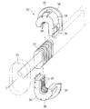
- the housing part 40 and the guide part 50 are parts constituting the protector P (see FIGS. 5 to 7).
- the accommodating part 40 is a part formed so that the wire harness WH extended from the other end part of the exterior member 20 can be accommodated so that the extra length can be absorbed.
- the guide part 50 is a part formed in the cylinder shape or groove
- the guide portion 50 has a guide port 52 into which the other end portion of the exterior member 20 can be inserted at one end portion, and the other end portion is continuous with one end portion of the housing portion 40.
- the accommodating part 40 is continuous with the other end part of the guide part 50 in one end part, and accommodates the wire harness WH extended from the other end part of the exterior member 20 inserted in the guide part 50 so that a surplus length can be absorbed. It has a possible accommodation space.
- the accommodating portion 40 has an outlet 44 through which the wire harness WH inserted in the accommodating space through the guide portion 50 can be pulled out into the door 6 (in the space between the door inner panel 7 and the trim 8). have.
- the protector P guides the exterior member 20 inserted into the guide portion 50 through the guide port 52 toward the housing portion 40, and the wire harness WH extended from the other end of the exterior member 20 is guided to the housing portion. It is a member that is accommodated in the accommodating space 40 so as to be able to absorb the extra length and extends outwardly, that is, into the door 6 through the outlet 44.
- the protector P is opened in the direction in which the guide port 52 and the outlet 44 are substantially orthogonal, and is formed in a substantially L shape in side view as a whole.
- the side surface of the protector P (wire harness wiring structure portion 10) is a surface parallel to the opening direction of the guide port 52 (guide direction of the guide portion 50) and the opening direction of the outlet 44.
- the protector P when the protector P is attached to the door 6, the front is viewed from the front of the door 6 and the side is viewed from the vehicle interior side.
- the protector P will be described in more detail by focusing on the configurations of the guide unit 50 and the storage unit 40.
- the guide portion 50 is formed in a cylindrical shape (here, a cylindrical shape having a substantially rectangular cross-sectional view) having an internal space larger than the exterior member 20 so that the exterior member 20 can be moved forward and backward. (See FIGS. 5 and 7). But the guide part 50 should just be able to insert and guide the exterior member 20, and may be formed in cylindrical shapes, such as cross-sectional view substantially elliptical shape, circular shape, or polygons other than a rectangle.
- the exterior member 20 is such that at least a part on the other end side is inserted into the guide portion 50 when the door 6 is open with the one end side portion fixed to the attachment member 30 attached to the vehicle body 2. Long extended dimensions are set.
- the guide unit 50 only needs to be able to regulate the position of the other end portion of the exterior member 20 that is advanced and retracted in the door 6 when the door 6 is opened and closed. In the closed state, the extension dimension is set such that the other end portion of the exterior member 20 protrudes into the housing portion 40. But the guide part 50 is longer than the said dimension, and may be set so that accommodation to the other end part of the exterior member 20 in the closed state of the door 6 is possible.
- the guide portion 50 may be formed such that a guide port 52 formed at one end thereof is expanded to the outer peripheral side (see FIGS. 5 to 7).
- the guide portion 50 adopts a shape that expands in all directions substantially orthogonal to the extending direction.
- the guide port 52 is formed so as to gradually expand toward one end.
- the accommodating portion 40 includes a wire harness WH extending from the other end portion of the exterior member 20 between the first route R1 and the second route R2 swelled so that the intermediate portion is separated from the first route R1. It is formed so as to be bent so as to be able to absorb the extra length (see FIG. 5).
- the accommodating portion 40 has a first wall portion 41 and a second wall portion 42 that are opposed to each other with the accommodating space in a side view.
- the wire harness WH accommodated in the accommodation space is disposed close to the first wall portion 41 when passing through the first route R1 and close to the second wall portion 42 when passing through the second route R2. .
- Each of the first wall portion 41 and the second wall portion 42 is continuous with the other end portion of the guide portion 50, and each other end portion forms a wall portion facing the outlet 44. More specifically, the first wall portion 41 extends so as to connect the other end portion of the guide portion 50 and the outlet 44 of the housing portion 40 on the inner peripheral side of the protector P having a substantially L shape in side view. is doing.
- the second wall portion 42 is spaced from the first wall portion 41 so that the wire harness WH can be bent and deformed, and is on the outer peripheral side of the substantially L-shaped protector P in side view, and the other end of the guide portion 50. It extends so as to connect the section and the outlet 44.
- the accommodating part 40 has the positioning part 46 in the door which can fix the wire harness WH at the outlet 44.
- the in-door positioning portion 46 is formed in a shape in which the opening edge of the outlet 44 partially extends (see FIGS. 5 to 7). Then, the wire harness WH drawn through the outlet 44 is in contact with the inside of the in-door positioning portion 46 and is fastened together with a tape T or tie band and fixed (here, tape T is wound). It is possible to position in the door 6 by fixing. Thereby, even if the wire harness WH on the vehicle body 2 side advances or retreats in the housing portion 40 during the opening / closing operation of the door 6, it is possible to prevent the wire harness WH routed in the door 6 from being pulled or loosened. it can.
- the configuration for fixing the wire harness WH to the accommodating portion 40 is not limited to the positioning portion 46 in the door.
- a plurality of hole portions for inserting tie bands may be formed in the door positioning portion extending in a wall shape from the outlet 44, and the wire harness WH may be fastened and fixed by inserting the tie band into the hole portion.
- the wire harness WH extended from the other end portion of the exterior member 20 is pushed into the accommodation space of the accommodation portion 40 as the door 6 is closed.
- the wire harness WH is changed from the first route R1 to the second route R2, but may be subjected to a heavy load depending on the form of the second route R2 when absorbing the extra length, such as being bent by a U-turn.
- the accommodating part 40 of this wire harness wiring structure part 10 is formed so that surplus length can be absorbed by the path
- the accommodating portion 40 has a wire harness WH larger than a path passing through a line along the guide direction (extending direction) of the guide portion 50 and a line perpendicular to the guide direction through the door positioning portion 46.
- the second wall portion 42 is formed so as to be able to restrict bending.
- the route passing through the line means that a part of the wire harness WH housed in the housing part 40 overlaps the line in the extending direction in a side view.
- the central axis of the wire harness WH does not necessarily have to pass on the line.
- the term “bent greatly” means that the wire is bent beyond the above-mentioned lines.
- the accommodating portion 40 is configured so that the wire harness WH extends in a line extending along the guide direction of the guide portion 50 and a portion of the wire harness WH that is fixed to the in-door positioning portion 46. It is preferable that the second wall portion 42 be formed so as to be able to regulate the path so as to bend into a path passing along the line along which the extra length is absorbed.
- the shape of the accommodating portion 40 is such that the wire harness WH passing through the second path R2 is bent before or on the line along the extending direction of the portion fixed to the in-door positioning portion 46. Shape.
- the accommodating portion 40 is configured to absorb the excess length by bending the wire harness WH into a path passing through a line along the guide direction of the guide portion 50 and a line orthogonal to the guide direction.
- the wall part 42 is formed so that path regulation is possible.
- the accommodating portion 40 is configured such that, in the opened state of the door 6, an intermediate portion between the other end portion of the exterior member 20 and the in-door positioning portion 46 is connected to the other end portion of the exterior member 20.
- the 1st wall part 41 is formed so that a path
- the second wall portion 42 includes a guide portion side wall portion 42a that is continuous with the other end portion of the guide portion 50, an outlet side wall portion 42b that forms one wall portion of the outlet 44, a guide portion side wall portion 42a, and an outlet side wall.
- the door positioning portion 46 described above is formed in an L shape in plan view with a portion extending from the other end portion of the outlet side wall portion 42b of the second wall portion 42 as one piece. That is, a portion of the wire harness WH that is fixed to the door positioning portion 46 extends along the extending direction in a state of being in contact with the outlet side wall portion 42b.
- the outlet 44 is formed so as to open in a direction substantially orthogonal to the guide port 52, and the fixing portion of the wire harness WH is guided by the guide 50 together with the door positioning portion 46 in a side view. It extends along a direction substantially orthogonal to the direction.
- the guide part side wall part 42a is a wall part extending linearly along the guide direction from the other end of the guide part 50 in a side view.
- the outlet side wall part 42b is a wall part extending along a direction substantially orthogonal to the guide part side wall part 42a in a side view.
- the outlet side wall part 42 b forms one wall part of the outlet 44 on the proximal end side of the door positioning part 46.
- the curved portion 42c is set in a gentle curved shape in a side view, and connects the other end portion of the guide portion side wall portion 42a and one end portion of the outlet side wall portion 42b.
- the wire harness WH is curved at a portion along the curved portion 42c in a form passing through the second route R2 along the second wall portion 42, and both side portions thereof are the guide portion side wall portion 42a and the outlet side wall. It is accommodated along a line substantially orthogonal along the portion 24b.
- the part accommodated along the bending part 42c among the wire harnesses WH is located inside the said substantially orthogonal line. Accordingly, the wire harness WH that absorbs the extra length is restricted from being bent beyond the position of the in-door positioning portion 46 in a direction away from the guide portion 50 (the rear side of the door 6 to be attached).
- the first wall portion 41 has a linear portion extending in a direction connecting the other end portion of the exterior member 20 and the in-door positioning portion 46 when the door 6 is open in a side view. Moreover, the edge part by the side of the guide part 50 among the 1st wall parts 41 continues in a gentle curve shape with respect to the other end part of the guide part 50, and the edge part by the side of the outlet 44 is formed in linear form. In addition, it is formed in a gently curved shape so as to connect the linear portions.
- the first wall 41 is closer to a line connecting the other end of the exterior member 20 and the in-door positioning portion 46 in the opened state of the door 6, that is, the wire harness WH is a first route R1 that is the shortest route. It is good to be provided at a position where wiring is possible. Thereby, the path
- the first wall 41 is second from the line connecting the other end of the exterior member 20 and the outlet 44 when the door 6 is open. It may be provided on the wall 42a side.
- the wire harness WH is fixed to the other end portion of the exterior member 20 and the door positioning portion 46 with a tape T, and when the door 6 is in an open state, a portion adjacent to both the fixing portions is its own. It is gently curved by the rigidity, and an intermediate portion between the two fixed portions extends substantially linearly (first path R1).
- first path R1 the linear portion of the wire harness WH passing through the first path R ⁇ b> 1 extends in parallel to the direction connecting the other end portion of the exterior member 20 and the in-door positioning portion 46 in the opened state of the door 6.
- the 1st wall part 41 is formed so that the linear intermediate part may extend along the linear part of the wire harness WH which passes 1st path
- the protector P is disposed in a recess 7 h formed in the door inner panel 7. More specifically, the protector P is formed to be able to be arranged in one direction with respect to the recess 7h (here, from the vehicle interior side toward the vehicle exterior side through the vehicle interior side opening of the recess 7h). .
- the guide portion 50 extends along the front-rear direction of the door 6, the guide portion 50 is positioned on the front side with respect to the housing portion 40, and the outlet 44 faces the upper side of the door 6. (See FIGS. 1 and 2). Further, the attachment position of the protector P will be described in relation to the manner of attachment of the attachment member 30 to the vehicle body 2.
- the attachment member 30 and the protector P are arranged such that the exterior member 20 is bridged below the opening degree restricting portion 3. These are formed so that they can be attached to the vehicle body 2 or disposed in the door 6.
- the protector P can be disposed in the door 6 such that the guide port 52 of the guide portion 50 is positioned below the door side connecting portion of the opening degree restricting portion 3.
- the concave portion 7h is formed in a concave shape having an accommodation space in which the protector P can be accommodated entirely or partially in the posture and the position. And the guide port 52 of the guide part 50 is exposed outside the door 6 through the opening part ahead of the door 6 among the recessed parts 7h.
- the protector P is formed so as to be attachable to the attachment posture and position by being pressed toward the outer side of the passenger compartment against the door inner panel 7 of the door 6.
- the protector P has the fixing
- the fixing portion 58 a base shaft portion that protrudes from the outer surface of the protector P (here, a first member P1 to be described later), and a spring portion that extends from the distal end portion to the outer peripheral side and elastic toward the inner peripheral side.
- a configuration having a deformable locking portion can be employed.
- the protector P may be fixed to the door inner panel 7 by screwing or the like. Even in this case, the protector P may be disposed from the vehicle interior side toward the vehicle exterior side with respect to the door inner panel 7 (recess 7h).
- the exterior member 20 spanned between the attachment member 30 and the guide part 50 (guide opening
- the exterior member 20 is partially fixed to the vehicle body 2 via the attachment member 30, slack between the attachment member 30 and the guide portion 50 is suppressed by its own rigidity, and the other end The side portion is advanced and retracted into the guide portion 50 more smoothly and reliably.
- the protector P is formed in a substantially L shape as a whole. For this reason, a space surrounded by the protector P is created on the inner side of the protector P, that is, above the guide portion 50 and in front of the housing portion 40 in the state of being disposed on the door 6.
- the protector P is positioned with respect to the recess 7 h in such a posture that the guide port 52 of the guide portion 50 is located below the fixed position of the case portion of the opening degree restricting portion 3 and the outlet 44 faces upward of the vehicle body 2.
- the protector P is disposed on the door 6 so as to surround the opening restriction portion 3 from two directions, and the arm portion of the opening restriction portion 3 advances and retreats in a space surrounded by the protector P. Thereby, the space in the door 6 in which several electric equipment is installed can be used effectively.
- the above-described protector P is configured by combining the first member P1 and the second member P2 (see FIGS. 6 and 7).
- a combination of a concave member and a lid member is employed as the first member P1 and the second member P2.
- the protector P can be obtained by casting the first member P1 and the second member P2 by pouring molten resin materials into a mold, and combining them.
- the first member P1 and the second member P2 may be formed so as to be able to maintain a combined state.
- a plurality of locking portions 72 or locked portions 74 are formed on the first member P1 and the second member P2, respectively, and each locking portion 72 is brought close to the first member P1 and the second member P2.
- the to-be-latched part 74 is good to be comprised so that it may latch (refer FIG. 6, FIG. 7).
- a wall-like locked part 74 provided at an interval on the outer surface of the protector P, and an insertion that can be inserted between the outer surface and the locked part 74
- a combination of a locking portion 72 having a piece and a protruding portion protruding outward from the distal end portion of the insertion piece can be employed. That is, when the insertion piece of the locking portion 72 is inserted between the outer surface of the protector P and the locked portion 74, the protruding portion of the locking portion 72 comes into contact with the edge of the locked portion 74. And is configured to be locked.
- the protector P is formed such that the guide port 52 and the outlet 44 are in a positional relationship shifted in the mounting direction with respect to the door 6 (see FIGS. 3 and 6).
- the wire harness WH bent in the accommodating part 40 receives the force around a central axis, and is deform
- the wire harness routing structure 10 may be assembled before the vehicle is assembled by modularizing the wire harness WH, the exterior member 20, the mounting member 30, and the protector P that are routed from the vehicle body 2 into the door 6. That is, the wire harness WH is disposed in the exterior member 20, the attachment member 30 is attached to one end portion of the exterior member 20, and the one end thereof is fixed by winding the tape T around the wire harness WH, and The other end of the exterior member 20 is wound around the wire harness WH with a tape T and fixed. And the other end side part of the exterior member 20 is arrange
- the other end portion of the exterior member 20 is positioned on one end side of the guide portion 50 compared to the closed state, and the wire harness WH extending from the other end portion of the exterior member 20 is: It is accommodated in the accommodation space through the first route R1. That is, the wire harness WH partially extends linearly along the straight portion of the first wall portion 41, and both side portions of the wire harness WH gradually move toward the other end portion of the exterior member 20 and the in-door positioning portion 46. It extends in a curved shape.
- the exterior member 20 moves forward into the guide portion 50, and the wire harness WH extended from the other end is pushed into the housing space and the second wall portion. 42a approaches.
- the wire harness WH is restricted from bending toward the rear side of the door 6 from the portion fixed to the door positioning portion 46 by the outlet side wall portion 42b.
- the wire harness WH is restricted from being bent in a direction away from the outlet 44 by the guide side wall 42a.
- the wire harness WH will be in the state accommodated in accommodation space through 2nd path
- the part accommodated in accommodation space among the wire harnesses WH becomes long, and extra length is absorbed.
- the surplus length absorption operation in which the wire harness WH is changed from the first route R1 to the second route R2, a bending operation in which the wire harness WH is U-turned is suppressed, and a load applied to the wire harness WH is reduced as much as possible. is doing.
- the extra length absorbing operation is set so that the wire harness WH is maintained in a bent state such that the both side portions of the bent portion intersect with each other at an angle of 90 degrees or more depending on the shape of the accommodating portion 40. Has been.
- the example has been described in which the outlet side wall part 42b of the second wall part 42 is formed in a straight line along the direction substantially orthogonal to the guide part side wall part 42a, but the shape of the accommodating part 40 is It is not limited.
- the accommodating part may be formed in a shape in which a portion of the outlet side wall part facing the guide part 50 swells in a direction away from the guide part 50 (the rear side of the door 6).
- the swelled portion of the outlet side wall portion is referred to as an inflating portion 148.
- FIG. 8 shows a protector Pa in which the outlet side wall portion 142 b of the second wall portion 142 of the accommodating portion 140 has an inflating portion 148.
- the protector Pa the only part different from the protector P is the expansion part 148, and the other parts are denoted by the same reference numerals as those of the protector P, and the description thereof is omitted.
- the inflatable portion 148 may be set so as to protrude smaller than the diameter of the wire harness WH with respect to the other portion (the portion that forms the outlet 44) of the outlet side wall 142b. That is, the portion of the wire harness WH passing through the second path R2 that is disposed along the outlet side wall 142b is along the extending direction of the portion that is fixed to the door positioning portion 46 in a side view. It passes on one line (the one-dot chain line in the vertical direction in FIG. 8).
- the extending direction of the in-door positioning portion 46 is not limited to the direction orthogonal to the guiding direction of the guiding portion 50, and may be inclined with respect to the guiding direction.
- the outlet side wall portion 42b may be formed so as to extend along the extending direction of the in-door positioning portion 46 and to be inclined with respect to the guide side wall portion 42a.
- the above-described inflating portion may be formed.
- the exterior member 20 does not need to be fixed to the wire harness WH from which the other end extends.
- the corrugated tube as the exterior member 20 is provided with a wire harness WH inside, a split (slit) may be formed in its extending direction, but the split opening is suppressed.
- the other end may be wound with a tape T.
- the wire harness WH may be fixed to the in-door positioning portion 46 with a tie band 92.
- the door positioning portion 46 may be formed with a hole through which the tie band 92 is passed.
- a tape T may be wound around a portion of the wire harness WH that is tightened by the tie band 92 as a measure against disconnection. That is, the tape T may be wound around the outer periphery of the wire bundle constituting the wire harness WH, and the tie band 92 may be tightened from above to fix the wire harness WH to the in-door positioning portion 46.
- the structure which winds the tape T around the wire harness WH as a countermeasure against disconnection can also be employed when the wire harness WH is fixed to the in-door positioning portion 46 by tape T winding.
- the attachment member 30 a member having a lock structure part capable of maintaining the combined state of a pair of U-shaped members as shown in FIG. 10 may be adopted.
- the attachment member 30 is formed at one end of each of the butted portions of the pair of U-shaped members, and at the other end, and the locking portion 37 can be locked.
- a receiving portion 39 a receiving portion 39.
- the locking portion 37 is a portion having a locking claw that protrudes from the distal end portion of the insertion portion that protrudes from one end portion of the U-shaped member toward the inner peripheral side of the U-shaped member.
- This locking claw is formed in a substantially triangular shape in a sectional view in which the protruding dimension gradually increases from the distal end side toward the proximal end side, and has a locking surface facing the proximal end side.
- the receiving part 39 is formed in the concave shape opened in the other end surface of a U-shaped member, and has the hole which can arrange
- the accommodating portion 40 and the guide portion 50 are not limited to being formed as a single-part protector P, and may be configured as separate parts.
- the accommodating part 40 and the guide part 50 are good to be arrange
- attachment member 30 and the protector P are not limited to the case where the exterior member 20 is formed so as to be attachable to a position located below the opening degree restriction unit 3, for example, above or side of the opening degree restriction unit 3. It may be attachable so that it is located in.
- the wire harness wiring structure portion 10 is applied between the vehicle body 2 and the door 6 as the front side door.
- the wire harness WH is bridged between the center pillar (the pillar between the front side door and the rear side door) and the rear side door. That is, a hole is formed in the center pillar, and the attachment member 30 is attached here.
- the guide member 50 guides the exterior member 20 that is sheathed on the wire harness WH, and the housing portion 40 extends from the other end portion of the exterior member 20. Since the harness WH is formed so as to be able to absorb the surplus length, the bending performance is improved by absorbing the surplus length by smoothly moving the wire harness WH back and forth in the door 6 as the door 6 opens and closes. be able to.
- the housing portion 40 is bent more than the path through which the wire harness WH passes through the line along the guide direction of the guide portion 50 and the in-door positioning portion 46 and the line orthogonal to the guide direction.
- the 2nd wall part 42 is formed so that control is possible. That is, the wire harness WH in the housing portion 40 is route-restricted by the second wall portion 42, and in a side view, the second route R2 at the time of absorbing the extra length passes through an orthogonal line or more gently. It becomes a bent form.
- the shape of the protector P of the wire harness routing structure 10 is effective when a relatively large force is required for bending deformation when absorbing the extra length, such as when the diameter of the wire harness WH is large.
- the accommodating part 40 was along the extending direction of the part currently fixed to the positioning part 46 in the door among the line along the guide direction of the guide part 50, and the wire harness WH in the side view.
- the second wall portion 42 is formed so as to be able to regulate the path so as to be bent into a path passing through the line and absorb the surplus length. For this reason, even when the extending direction of the portion fixed to the door positioning portion 46 of the wire harness WH is inclined with respect to the direction orthogonal to the guide direction of the guide portion 50, the load applied to the wire harness WH is further reduced. be able to.
- the accommodating portion 40 absorbs the extra length by bending the wire harness WH into a path passing through a line along the guide direction of the guide portion 50 and a line orthogonal to the guide direction of the guide portion 50. Since the 2nd wall part 42 is formed so that path
- the intermediate portion between the other end of the exterior member 20 and the door positioning portion 46 in the wire harness WH is connected to the other end of the exterior member 20. Since the first wall portion 41 is formed so as to be able to regulate the path so as to be accommodated in a path parallel to the direction connecting the in-door positioning portion 46, the load applied to the wire harness WH can be reduced in the opened state of the door 6. At the same time, the path difference between the first path R1 and the second path R2 can be increased to ensure a larger extra length absorption space.
- the first wall portion 41 of the accommodating portion 40 has a linear portion extending along a direction connecting the other end portion of the exterior member 20 and the in-door positioning portion 46 in the open state of the door.
- the wall portion 42 has a guide portion side wall portion 42a extending along the guide direction of the guide portion 50, and the portion of the wire harness WH fixed by the in-door positioning portion 46 is extended through the curved portion 42c. It is formed so as to have an outlet side wall portion 42b extending along the existing direction. For this reason, the load added to the wire harness WH at the time of opening and closing of the door 6 can be reduced, ensuring the surplus length absorption space of the wire harness WH large. Moreover, the dimension which protrudes in the back side of the door 6 from the in-door positioning part 46 among the protectors P can be made small.
- the exterior member 20 is a flat corrugated tube having higher rigidity than the wire harness WH, and is bridged between the vehicle body 2 and the door 6 in a flat posture along the vertical direction, the wire harness WH It is possible to suppress bending and sagging while enabling bending deformation in the horizontal direction in the entire portion spanned between the vehicle body 2 and the door 6. Thereby, the wire harness WH can be more reliably advanced and retracted into the guide portion 50 and the accommodating portion 40 in accordance with the opening / closing operation of the door 6, and the extra length can be absorbed smoothly.
- the mounting member 30 is fitted only by positioning the one end side portion of the exterior member 20 that is sheathed on the wire harness WH by the vehicle body side fitting portion 38 and pressing it toward the insertion direction S against the hole 2h. Therefore, the wire harness WH can be easily routed to the vehicle body 2 side.
- the exterior member 20 is formed in a flat shape and is provided in a flat posture along the vertical direction of the vehicle body 2, the exterior member 20 can be routed in a narrow space in the inside and outside of the door 6 and is disposed in the door 6.
- the guide part 50 and the accommodating part 40 to be made can also be made flat, and can be applied even in the case of the door 6 in which the space between the door inner panel 7 and the trim 8 is narrow.
- the exterior member 20 is provided in a flat posture along the vertical direction of the vehicle body 2, it is relatively difficult to bend in the vertical direction, and the hanging of the wire harness WH can be suppressed.
- the member for water-stopping such as a grommet
- omitted a reduction in a number of parts and an assembly man-hour Therefore, it is possible to reduce costs and improve work efficiency.
- the structure which does not use a grommet it can abbreviate
- the expansion work of the grommet at the time of letting the wire harness WH pass can also be omitted.
- the wire harness wiring structure part 10 since the wire harness wiring structure part 10 has wired the wire harness WH between the door inner panel 7 and the trim 8, it can save the effort which inserts and wires the wire harness WH through a through-hole. Assembling work can be performed in the exposed work space, so that assembling performance can be improved and work efficiency can be improved.
- wire harness wiring structure 10 has been described in detail, but the above description is an example in all aspects, and the present invention is not limited thereto. It is understood that countless variations that are not illustrated can be envisaged without departing from the scope of the present invention.
Landscapes
- Engineering & Computer Science (AREA)
- Mechanical Engineering (AREA)
- Architecture (AREA)
- Civil Engineering (AREA)
- Structural Engineering (AREA)
- Electric Cable Arrangement Between Relatively Moving Parts (AREA)
- Details Of Indoor Wiring (AREA)
Abstract
L'invention concerne une structure de cheminement de faisceaux de câbles constituée de: un faisceau de câbles; une section de boîtier qui comporte un élément extérieur de couverture, qui couvre l'extérieur du faisceau de câbles; un élément de fixation, qui peut être fixé à la carrosserie d'un véhicule et est monté sur une section terminale de l'élément extérieur de couverture; et une section de mise en place intérieure de porte qui, d'une manière capable d'absorber une longueur excédentaire, accueille le faisceau de câbles s'étendant depuis l'autre extrémité de l'élément extérieur de couverture et peut fixer le faisceau de câbles au niveau d'une ouverture de sortie par laquelle on peut tirer le faisceau de câbles dans la porte; et une section guide qui peut guider l'autre section terminale de l'élément extérieur de couverture vers la section de boîtier. La section de boîtier comporte une section de paroi qui, en vue latérale, peut éviter au faisceau de câbles de se courber plus qu'un parcours traversant une ligne le long de la direction de guidage de la section guide et une ligne perpendiculaire à la direction de guidage à travers la section de mise en place intérieure de porte.
Applications Claiming Priority (2)
| Application Number | Priority Date | Filing Date | Title |
|---|---|---|---|
| JP2011-028317 | 2011-02-14 | ||
| JP2011028317A JP5630307B2 (ja) | 2011-02-14 | 2011-02-14 | ワイヤーハーネス配索構造部 |
Publications (1)
| Publication Number | Publication Date |
|---|---|
| WO2012111182A1 true WO2012111182A1 (fr) | 2012-08-23 |
Family
ID=46672138
Family Applications (1)
| Application Number | Title | Priority Date | Filing Date |
|---|---|---|---|
| PCT/JP2011/064390 Ceased WO2012111182A1 (fr) | 2011-02-14 | 2011-06-23 | Structure de cheminement de faisceaux de câbles |
Country Status (2)
| Country | Link |
|---|---|
| JP (1) | JP5630307B2 (fr) |
| WO (1) | WO2012111182A1 (fr) |
Cited By (3)
| Publication number | Priority date | Publication date | Assignee | Title |
|---|---|---|---|---|
| JP2014093805A (ja) * | 2012-11-01 | 2014-05-19 | Sumitomo Wiring Syst Ltd | ワイヤーハーネス配索構造部 |
| EP3578861A1 (fr) * | 2018-06-04 | 2019-12-11 | Binder GmbH | Guidage de conduite permettant de guider au moins un faisceau de conduites entre deux éléments |
| EP3691063A1 (fr) * | 2019-01-31 | 2020-08-05 | Yazaki Corporation | Structure de connexion de tubes de protection |
Families Citing this family (1)
| Publication number | Priority date | Publication date | Assignee | Title |
|---|---|---|---|---|
| JP2025110009A (ja) * | 2024-01-15 | 2025-07-28 | 矢崎総業株式会社 | ワイヤハーネスの配索構造 |
Citations (2)
| Publication number | Priority date | Publication date | Assignee | Title |
|---|---|---|---|---|
| JP2006117054A (ja) * | 2004-10-20 | 2006-05-11 | Sumitomo Wiring Syst Ltd | ワイヤハーネス配索構造 |
| JP2006149109A (ja) * | 2004-11-22 | 2006-06-08 | Furukawa Electric Co Ltd:The | 余長吸収装置 |
Family Cites Families (1)
| Publication number | Priority date | Publication date | Assignee | Title |
|---|---|---|---|---|
| JP2008062784A (ja) * | 2006-09-07 | 2008-03-21 | Yazaki Corp | 常時給電装置 |
-
2011
- 2011-02-14 JP JP2011028317A patent/JP5630307B2/ja not_active Expired - Fee Related
- 2011-06-23 WO PCT/JP2011/064390 patent/WO2012111182A1/fr not_active Ceased
Patent Citations (2)
| Publication number | Priority date | Publication date | Assignee | Title |
|---|---|---|---|---|
| JP2006117054A (ja) * | 2004-10-20 | 2006-05-11 | Sumitomo Wiring Syst Ltd | ワイヤハーネス配索構造 |
| JP2006149109A (ja) * | 2004-11-22 | 2006-06-08 | Furukawa Electric Co Ltd:The | 余長吸収装置 |
Cited By (7)
| Publication number | Priority date | Publication date | Assignee | Title |
|---|---|---|---|---|
| JP2014093805A (ja) * | 2012-11-01 | 2014-05-19 | Sumitomo Wiring Syst Ltd | ワイヤーハーネス配索構造部 |
| EP3578861A1 (fr) * | 2018-06-04 | 2019-12-11 | Binder GmbH | Guidage de conduite permettant de guider au moins un faisceau de conduites entre deux éléments |
| US10753510B2 (en) | 2018-06-04 | 2020-08-25 | Binder Gmbh | Conduit guide for guiding at least one conduit section between two elements |
| EP3691063A1 (fr) * | 2019-01-31 | 2020-08-05 | Yazaki Corporation | Structure de connexion de tubes de protection |
| CN111509643A (zh) * | 2019-01-31 | 2020-08-07 | 矢崎总业株式会社 | 保护管连接结构 |
| US11217975B2 (en) | 2019-01-31 | 2022-01-04 | Yazaki Corporation | Protective tube connection structure |
| CN111509643B (zh) * | 2019-01-31 | 2022-05-27 | 矢崎总业株式会社 | 保护管连接结构 |
Also Published As
| Publication number | Publication date |
|---|---|
| JP2012166650A (ja) | 2012-09-06 |
| JP5630307B2 (ja) | 2014-11-26 |
Similar Documents
| Publication | Publication Date | Title |
|---|---|---|
| WO2012070268A1 (fr) | Structure de cheminement de câblage pour faisceau électrique, et élément protecteur | |
| CN103648846B (zh) | 线束布线结构部 | |
| US9511725B2 (en) | Wiring harness wiring structure | |
| WO2012150643A1 (fr) | Section de structure d'acheminement de faisceau électrique | |
| JP2012176646A (ja) | ワイヤーハーネス配索構造 | |
| JP5644596B2 (ja) | ワイヤーハーネス配索構造部 | |
| WO2012147223A1 (fr) | Structure de routage de faisceau de câbles | |
| JP5630307B2 (ja) | ワイヤーハーネス配索構造部 | |
| JP5549558B2 (ja) | ワイヤーハーネス配策構造部 | |
| JP2013247805A (ja) | ワイヤーハーネス配索構造部 | |
| WO2012153436A1 (fr) | Structure d'acheminement de faisceau de câbles | |
| JP5445410B2 (ja) | ワイヤーハーネス配策構造部 | |
| JP5853932B2 (ja) | ワイヤーハーネス配索構造部 | |
| JP2013226961A (ja) | ワイヤーハーネス配索構造部 | |
| JP4412150B2 (ja) | グロメットを用いたワイヤハーネスの配索構造 | |
| WO2012124200A1 (fr) | Élément structural d'acheminement de faisceau de fils | |
| JP2008308070A (ja) | プロテクタ | |
| JP5799937B2 (ja) | グロメット、およびワイヤーハーネス配索構造部 | |
| JP2012111401A (ja) | ワイヤーハーネス配索構造部 | |
| JP2012178907A (ja) | ワイヤーハーネス配索構造 | |
| JP2012176649A (ja) | ワイヤーハーネス配索構造 | |
| WO2012127723A1 (fr) | Dispositif de câblage de porte | |
| JP2012182964A (ja) | コルゲートチューブ及びドア用配線装置 | |
| JP6078981B2 (ja) | ワイヤーハーネス配索構造部 | |
| JP2012111407A (ja) | ワイヤーハーネス配索構造部 |
Legal Events
| Date | Code | Title | Description |
|---|---|---|---|
| 121 | Ep: the epo has been informed by wipo that ep was designated in this application |
Ref document number: 11858661 Country of ref document: EP Kind code of ref document: A1 |
|
| NENP | Non-entry into the national phase |
Ref country code: DE |
|
| 122 | Ep: pct application non-entry in european phase |
Ref document number: 11858661 Country of ref document: EP Kind code of ref document: A1 |