WO2012111377A1 - Dispositif et système de surveillance de l'utilisation de l'électricité - Google Patents
Dispositif et système de surveillance de l'utilisation de l'électricité Download PDFInfo
- Publication number
- WO2012111377A1 WO2012111377A1 PCT/JP2012/051029 JP2012051029W WO2012111377A1 WO 2012111377 A1 WO2012111377 A1 WO 2012111377A1 JP 2012051029 W JP2012051029 W JP 2012051029W WO 2012111377 A1 WO2012111377 A1 WO 2012111377A1
- Authority
- WO
- WIPO (PCT)
- Prior art keywords
- power
- usage monitoring
- amount
- estimated
- meter
- Prior art date
- Legal status (The legal status is an assumption and is not a legal conclusion. Google has not performed a legal analysis and makes no representation as to the accuracy of the status listed.)
- Ceased
Links
Images

Classifications
-
- G—PHYSICS
- G01—MEASURING; TESTING
- G01R—MEASURING ELECTRIC VARIABLES; MEASURING MAGNETIC VARIABLES
- G01R22/00—Arrangements for measuring time integral of electric power or current, e.g. electricity meters
- G01R22/06—Arrangements for measuring time integral of electric power or current, e.g. electricity meters by electronic methods
- G01R22/061—Details of electronic electricity meters
- G01R22/066—Arrangements for avoiding or indicating fraudulent use
-
- G—PHYSICS
- G06—COMPUTING OR CALCULATING; COUNTING
- G06Q—INFORMATION AND COMMUNICATION TECHNOLOGY [ICT] SPECIALLY ADAPTED FOR ADMINISTRATIVE, COMMERCIAL, FINANCIAL, MANAGERIAL OR SUPERVISORY PURPOSES; SYSTEMS OR METHODS SPECIALLY ADAPTED FOR ADMINISTRATIVE, COMMERCIAL, FINANCIAL, MANAGERIAL OR SUPERVISORY PURPOSES, NOT OTHERWISE PROVIDED FOR
- G06Q10/00—Administration; Management
- G06Q10/06—Resources, workflows, human or project management; Enterprise or organisation planning; Enterprise or organisation modelling
Definitions
- the present invention relates to a power usage monitoring device used for monitoring the presence or absence of power usage from the primary side of a power meter, and to a power usage monitoring system for notifying a management device of the results of monitoring by the power usage monitoring device. .
- a power meter is installed in a power consumer, and the amount of power used by the consumer is measured using the power meter. Therefore, the power supply company (electric power company) charges the electricity bill by trusting the meter reading value of the power meter. In other words, if a bypass line that does not pass through the power meter is attached, the power is used without being measured by the power meter, and the power supplier loses the basis for charging the electricity bill. In other words, when so-called stealing is performed by attaching a bypass line, there arises a problem that the profit of the power supply company is compressed.
- Document 1 Japanese Patent Application Publication No. 2004-340767
- Document 1 has a branch between a first distribution line connected to a substation and a second distribution line that supplies power to consumers.
- the technique which pays attention to the current in / out of the point is described.
- the configuration described in Document 1 is based on the principle that the amount of current flowing into the branch point must match the amount of current flowing out of the branch point.
- current detection devices are respectively provided on the upstream side and the downstream side of the branch point in the first distribution line.
- the amount of current supplied from the branch point to the consumer is obtained from the meter reading value of a watt-hour meter (that is, a power meter) provided in the second distribution line.
- a watt-hour meter that is, a power meter
- Document 2 divides a region where power is supplied into a plurality of regions, and further includes a plurality of regions.
- a technique is described in which the electric power is divided into areas and the electric energy for each area and the electric energy for each area are measured.
- the configuration described in Document 2 is based on the principle that, in a hierarchical distribution network, the total amount of power used in the lower layer must match the amount of power in the upper layer.
- a power accumulator that measures the amount of power used in one area and a power amount accumulator that measures the amount of power used for each area (which can be read as a consumer) that divides the area (power) Which can be read as a meter).
- the total amount of electric power measured by the electric energy accumulator provided for each area is compared with the electric energy measured by the electric energy accumulator provided in the area, and both values are different (the electric energy in the area). If the total amount of power in the area is smaller), it is detected as an abnormality such as theft.
- the amount of current or power is measured at a plurality of locations, and if the planned relationship is not established between the measured amount of current or power, It is judged that such an abnormality has occurred. Therefore, in addition to the power meter installed for each consumer, a device that measures the amount of current or the amount of power is required, and both the measurement results of those devices and the power meter are measured using communication technology. An apparatus for obtaining and determining whether there is an abnormality is required. That is, in order to adopt the techniques described in Documents 1 and 2 in the existing distribution network, the communication function is provided for both the current detection device and the electric energy integrator installed in the distribution line and the electric power meter installed in the consumer. Is required. In addition, since the techniques described in Documents 1 and 2 require a communication function for the power meter, an existing power meter that does not have a communication function for remote meter reading or the like must be replaced.
- the present invention uses only one of the amount of power measured by the power distribution network and the amount of power measured by the power meter.
- the purpose is to provide a power usage monitoring device that suppresses an increase in capital investment in the network, and further uses this power usage monitoring device to monitor whether power is being used from the primary side of the power meter.
- the purpose is to provide a monitoring system.
- the power usage monitoring device of the present invention includes a measuring instrument, an estimated power storage unit, an abnormality determination unit, and a notification unit.
- the meter is configured to measure power supplied to a plurality of consumers.
- the estimated power storage unit stores in advance an estimated range of the amount of power that should be consumed by the entire consumer in a predetermined period.
- the abnormality determination unit is configured to determine that a state in which a total power amount for the plurality of consumers obtained from the measuring instrument exceeds an estimated range stored in the estimated power storage unit is abnormal.
- the notification unit is configured to notify abnormality information when the abnormality determination unit determines that an abnormality has occurred.
- the measuring instrument is a watt hour meter that is arranged on an electric circuit that supplies power to a plurality of consumers and measures the total amount of power that is supplied to the whole of the consumers.
- the abnormality determination unit is configured to determine that a state in which the total electric energy measured by the watt hour meter exceeds the estimated range stored in the estimated power storage unit in a predetermined period is abnormal.
- the measuring device is a power amount acquisition unit configured to acquire, by communication, the amount of power received for each consumer from a power meter that is disposed in each of the plurality of consumers and has a communication function.
- the abnormality determination unit is configured to determine that a state in which the total amount of power measured by the power meter in a predetermined period exceeds the estimated range stored in the estimated power storage unit is abnormal.
- the estimated power storage unit, the abnormality determination unit, and the notification unit are attached to a transformer that supplies power to the entire consumer.
- the notification unit is configured to notify abnormality information along with the position of the watt-hour meter to the management device through the communication network.
- the notification unit is configured to perform notification by visual stimulation.
- the notification unit is configured to perform notification by auditory stimulation.
- a power usage monitoring system includes the power usage monitoring device and a management device that communicates with the power usage monitoring device via a communication network, and the abnormality information is notified from the power usage monitoring device to the management device via the communication network. Configured to be.
- the configuration of the present invention it is possible to detect whether power is being used from the primary side of the power meter by using only one of the power amount measured by the distribution network and the power amount measured by the power meter. As a result, there is an advantage that an increase in capital investment for the existing power distribution network can be suppressed.
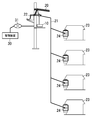
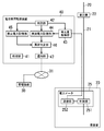
- FIG. 1 is a block diagram illustrating a first embodiment. It is a whole block diagram same as the above.
- FIG. 6 is a block diagram illustrating a second embodiment.
- a watt hour meter is arranged on a power circuit that supplies power to a plurality of consumers of interest in the distribution network, and power is illegally used from the primary side of the power meter based on the amount of power measured by the watt hour meter.
- the structure which estimates whether it is done is employ
- the plurality of consumers of interest in the present embodiment is a group of consumers that are receiving (consuming) power from the secondary side of one transformer provided by the power supply company in the distribution network. It is arranged on the secondary side of the transformer and on the upstream side of the branch point of the distribution network to each customer.
- the transformer means a step-down transformer disposed on a power pole, above the ground, underground, in a building, or the like.
- the amount of power measured by the watt-hour meter is the total amount of power received by the customer group from the secondary side of one transformer and the amount of power lost in the distribution network from the transformer to the power meter. And the total. Therefore, if the amount of power supplied from the secondary side of the transformer is compared with the total amount of power received by the customer group, the power is incorrect between the transformer and the power meter (that is, the primary side of the power meter). It can be determined whether or not it is used.
- the power meter requires a communication function, and the existing power meter is replaced. Will require a large amount of capital investment. Therefore, in the configuration in which the communication function is provided in the power meter for each consumer, the spread is hindered.
- the total amount of power received by the group of consumers on the secondary side of the transformer changes from moment to moment, but in a predetermined period in units of several hours, one day, one week, one month, etc.
- Knowledge has been obtained that the total power received by the group is regular. For example, if the unit is several hours or one day, the total amount of power varies depending on the time of day and the day of the week, but there is no significant change in the total amount of power on the same day of each day or day of the week. Can be estimated.
- the unit is one week or one month
- the total electric energy varies depending on the season, but the amount of change in the total electric energy can be estimated in the adjacent week or adjacent month, and the total electric power in the same week or month of the year can be estimated. It can be estimated that there is no significant change in quantity. That is, if the period and the number of consumers are appropriate, the total power amount in the predetermined period can be estimated with a relatively small error range based on past results and the like.
- the total amount of power to be received in a predetermined period by a group of consumers on the secondary side of the transformer is estimated using the total amount of power and time information. By using additional information, it is estimated with higher accuracy.
- the total power supplied to the consumer group from the secondary side of the transformer uses the measured value measured by the watt hour meter, and uses the estimated value as the total power to be received by the consumer group.
- a configuration is adopted in which presence or absence of use of power from the primary side of the power meter is detected.
- each consumer 23 includes a power meter 24, and the power meter 24 measures the amount of power received by the consumer 23.
- a power usage monitoring device 10 is disposed in the vicinity of the transformer 22.
- the power usage monitoring device 10 is arranged on the upstream side of the distribution network 21 on the secondary side of the transformer 22 with respect to the part where the distribution network 21 for distributing power to each consumer 23 branches.
- the power usage monitoring device 10 is provided to monitor the presence or absence of power usage from the primary side (upstream side) of the power meter 24, and from the upstream side (transformer 22 side) of the power usage monitoring device 10. It is preferable to dispose as close to the secondary side of the transformer 22 as possible so that power is not extracted.
- EPS Electric Pipe Shaft
- the main part of the power usage monitoring apparatus 10 is constituted by a microcomputer (microcomputer), and the functions of each component described below are realized by executing an appropriate program by the microcomputer.
- the power usage monitoring apparatus 10 includes a program for causing the microcomputer to operate as each configuration described below.
- the power usage monitoring apparatus 10 also includes a configuration that is not included in the microcomputer. Note that a PLD (Programmable Logic Device) other than the microcomputer may be used.
- the power usage monitoring apparatus 10 includes a processing unit 11 that performs overall control and monitoring of each configuration described below, and a clock unit 12 that measures the date and time.
- the processing unit 11 monitors the operation of each component of the power usage monitoring device 10 and gives an instruction to each component of the power usage monitoring device 10 at an appropriate timing.
- the watt-hour meter 13 provided in the power usage monitoring device 10 measures the amount of power supplied from the secondary side of the transformer 22 to the consumer 23.
- the watt-hour meter 13 measures the total amount (total amount of power) of the amount of power supplied to all the consumers 23 that receive power from the secondary side of the transformer 22.
- the electric energy meter 13 is an electronic type, and calculates the electric energy from the voltage detected by the voltage sensor and the current detected by the current sensor.
- a voltage dividing resistor is used for the voltage sensor
- a current transformer is used for the current sensor, for example.
- the calculation means for calculating the amount of electric power from the detected voltage and current is constituted by the microcomputer described above.
- the power usage monitoring device 10 includes an actually measured power storage unit 14 that stores the power amount measured by the watt hour meter 13 in association with the date and time that the clock unit 12 is timing. That is, the processing unit 11 is configured to measure the amount of power measured by the watt hour meter 13 at a predetermined time (for example, 1 second, 30 seconds, 1 minute) counted by the clock unit 12, In association with each other, the measured power storage unit 14 accumulates them. The processing unit 11 not only stores the power amount and the date and time in association with each other in the actual power storage unit 14 but also stores the integrated value of the power amount in the predetermined period in the actual power storage unit 14.
- a predetermined time for example, 1 second, 30 seconds, 1 minute
- the power usage monitoring apparatus 10 includes an estimated power storage unit 15 that stores in advance an estimated range of the amount of power that should be received from the secondary side of the transformer 22 by the entire consumer 23 during the predetermined period described above.
- the entire consumer 23 is the meaning of all the consumers 23 (customer group) that should receive power from the secondary side of one transformer 22.
- the estimation range of the amount of power stored in the estimated power storage unit 15 estimates the amount of power supplied to the customer group in a predetermined period from past results, and takes into account estimation errors and loss in the distribution network 21 and the like. It is determined.
- the estimated range of the amount of power stored in the estimated power storage unit 15 is It is associated with a period.
- the estimated power storage unit 15 is registered in advance with a set of the estimation range and period of the electric energy.
- the processing unit 11 designates the period in the estimated power storage unit 15, thereby The estimated range of the corresponding power amount can be extracted from the estimated power storage unit 15. Now, let us assume a case where one day from midnight of the previous day to midnight of the current day is defined as a period, and the estimated power storage unit 15 stores the estimation range of the daily power amount in this period.
- the power usage monitoring apparatus 10 compares the measured value of the power amount for the predetermined period stored in the measured power storage unit 14 with the estimated range of the power amount for the predetermined period stored in the estimated power storage unit 15 in advance.
- An abnormality determination unit 16 is provided. That is, the processing unit 11 stores the amount of power for one day in the measured power storage unit 14 and then instructs the abnormality determination unit 16 so that the amount of power stored in the measured power storage unit 14 is the estimated power storage unit 15. Is determined to be within the estimated range of daily power stored in the abnormality determination unit 16. Note that since the estimation range of the electric energy also changes when the date and time are different, the processing unit 11 sets the estimation range of the electric energy according to the period corresponding to the electric energy stored in the actual measurement electric power storage unit 14. It is preferable to extract from.
- the abnormality determination unit 16 determines that there is an abnormality between. In particular, when power is used illegally from the primary side of the power meter 24, the amount of power stored in the measured power storage unit 14 rather than the estimated range of power stored in the estimated power storage unit 15. It is predicted that the relationship will increase. Therefore, the abnormality determination unit 16 determines that power is used illegally from the primary side of the power meter 24 when this relationship is established.
- the measured power storage unit 14 stores the power amount for each short time, and when the abnormality determination unit 16 compares the power amount, the processing unit 11 calculates the total power amount. .
- the actual power storage unit 14 may calculate the total amount of power during the comparison by the abnormality determination unit 16 without storing the power amount during a predetermined period.
- the measured power storage unit 14 does not store the power amount for each short time, but stores the integrated value of the power amount, and uses the integrated value of the power amount for a predetermined period for comparison in the abnormality determination unit 16. Also good. If this configuration is adopted, the amount of data stored in the measured power storage unit 14 is reduced, so that a semiconductor memory having a small storage capacity can be used as the measured power storage unit 14.
- the power usage monitoring device 10 includes a notification unit 17 that notifies abnormality information when the abnormality determination unit 16 determines that an abnormality has occurred.
- the notification unit 17 can employ various configurations. For example, a configuration in which abnormal information is notified by visual stimulation or auditory stimulation can be employed.
- the notification by visual stimulation uses an appropriate light emitting element such as a light emitting diode, and when the abnormality determining unit 16 determines that an abnormality has occurred, the light emitting element is turned on or the light emitting element is blinked and turned on. Notice.
- abnormality information may be notified using a display such as a liquid crystal display or an organic EL display as the notification unit 17.
- a technology that sounds a buzzer or generates a voice message is used.
- the abnormality determination unit 16 is configured so that it cannot be reset unless it is an engineer of a power supply company.
- the notification by the visual stimulus or the auditory stimulus is performed at the place where the power usage monitoring apparatus 10 is arranged, it is necessary to go to the place where the transformer 22 is arranged in order to know whether or not an abnormality has occurred. Therefore, it is preferable to know whether or not an abnormality has occurred according to the meter reading of the power meter 24. That is, it is preferable to set a period for comparison by the abnormality determination unit 16 in accordance with the timing of meter reading.
- the notification unit 17 may be configured to have a communication function for notifying the management apparatus 30 of abnormality information through the communication path 31.
- the presence / absence of an abnormality can be known remotely without going to the place where the power usage monitoring device 10 is located. That is, if the communication path 31 can be maintained, the notification unit 17 may be provided with a communication function. In order to adopt this configuration, it is necessary to notify the abnormality information together with the position of each power usage monitoring device 10 in order to know the location of the transformer 22 where the abnormality has occurred.
- information on the position measured by a position measuring device such as GPS can be used. Further, if the fact that the power usage monitoring apparatus 10 is attached to the transformer 22 is used, information indicating the position of the transformer 22 can be used as the position information of the power usage monitoring apparatus 10.
- a terminal device for maintenance (not shown) is connected to an interface (not shown) of the power usage monitoring device 10, and location information is registered in the power usage monitoring device 10 from the terminal device.
- the management device 30 manages the identification information (communication address, etc.) of the power usage monitoring device 10 and the position of the installation location of the power usage monitoring device 10 in association with each other, the power usage The identification information of the monitoring device 10 may be used instead of the position information.
- the plurality of consumers 23 to be focused on are consumers receiving power from the same transformer 22. It may not be 23.
- This configuration is particularly effective when there are a plurality of transformers 22 in a single building, such as an apartment house. Even in this configuration, it is desirable to measure the amount of power supplied to the consumer 23 on the secondary side of the transformer 22. Therefore, it is preferable to obtain the total amount of power supplied to the consumer 23 of interest by providing a watt-hour meter 13 for each transformer 22 and communicating between the watt-hour meters 13 to be aggregated.
- the amount of power received by the entire consumer 23 in a predetermined period varies not only by the date and time but also by external factors such as temperature and weather (mainly environmental external factors). Therefore, if necessary, a temperature sensor that monitors the temperature, an illuminance sensor that monitors the illuminance, a weather sensor that monitors the weather, and the like may be provided.
- the first embodiment employs a configuration in which the power usage monitoring device 10 includes a watt hour meter 13 in order to measure the power supplied to the consumer 23 from the secondary side of the transformer 22. Yes. That is, while using the power meter 24 having only the function of measuring the amount of power received (consumed) by the consumer 23, it is detected that the power is illegally used from the primary side of the power meter 24.
- the power meter 25 installed in each consumer 23 communicates with the measurement unit 251 that measures the amount of power received by the consumer 23 and the power amount measured by the measurement unit 251 as information. And a communication unit 252.
- the power usage monitoring device 40 is arranged in the vicinity of the transformer 22 as in the first embodiment.
- the power usage monitoring device 40 acquires the amount of power measured by the power meter 25 by communicating with the power meter 25 instead of measuring the power supplied from the secondary side of the transformer 22.
- a communication technique between the power meter 25 and the power usage monitoring device 40 a technique of power line carrier communication using the distribution network 21 as a communication path is used.
- the power usage monitoring device 40 of the present embodiment obtains the amount of power received by the customer 23 by communicating with the communication unit 252 of the power meter 25 instead of the watt hour meter 13 of FIG. A quantity acquisition unit 43 is provided.
- Other configurations of the power usage monitoring apparatus 40 are the same as those of the power usage monitoring apparatus 10 described in the first embodiment. That is, reference numerals 41, 42, 44, 45, 46, and 47 in the present embodiment can be read as reference numerals 11, 12, 14, 15, 16, and 17 in the first embodiment, respectively.
- the power usage monitoring device 40 includes a processing unit 41 that performs overall control and monitoring of each component, a clock unit 42 that measures the date and time, and a power amount acquisition unit 43 that acquires a power amount measured by the power meter 25. .
- the power usage monitoring device 40 includes a measured power storage unit 44 that stores the power amount acquired by the power amount acquisition unit 43 in association with the date and time that the clock unit 42 is measuring, and the consumer 23 throughout the predetermined period.
- An estimated power storage unit 45 that stores an estimated range of the amount of power to be received in advance is provided.
- the power usage monitoring device 40 compares the measured value of the power amount for a predetermined period stored in the measured power storage unit 44 with the estimated range of the power amount for the predetermined period stored in advance in the estimated power storage unit 45.
- An abnormality determination unit 46 is provided.
- the power usage monitoring device 40 also includes a notification unit 47 that notifies abnormality information when the abnormality determination unit 46 determines that an abnormality has occurred.
- the power usage monitoring device 40 acquires the amount of power measured by the power meter 25 for each consumer 23 that is supplying power from the secondary side of the transformer 22. Moreover, the electric energy acquisition part 43 totals the electric energy for every consumer 23 acquired from each electric power meter 25, and calculates
- the power amount stored in the actually measured power storage unit 44 is compared with the estimated range of the power amount stored in the estimated power storage unit 45 in the abnormality determination unit 46 to determine whether there is an abnormality in the power supply.
- the notification unit 47 notifies the occurrence of the abnormality.
- the notification unit 47 is provided with a communication function for communicating with the power meter 25, and the power meter 25 notifies the display of abnormal information by a light emitting element or a buzzer. You may make it perform.
- the power meter 25 may be provided with a liquid crystal display, an organic EL display, or the like to notify abnormality information.
- the estimated power storage unit 45 stores the estimated range of the amount of power that should be received by the entire consumer 23 from the secondary side of the transformer 22 in the predetermined period described above,
- the whole consumer 23 means all the consumers 23 (customer groups) that should receive power from the secondary side of one transformer 22. Therefore, if power is used illegally on the primary side of the power meter 25, the actually measured power amount is considered to be smaller than the estimated range.
- the abnormality determination unit 46 if the amount of power stored in the measured power storage unit 44 is smaller than the estimated range of power stored in the estimated power storage unit 45, the power is illegal on the primary side of the power meter 25. It is determined that it has been used.
- the estimation range of the energy is set based on P ⁇ n.
- the first embodiment compares the amount of electric power supplied from the secondary side of the transformer 22 to the consumer 23 with the estimated range of the electric energy, whereas the present embodiment is different from each consumer 23.
- the electric energy measured by the electric power meter 25 is compared with the estimated range of electric energy.
- Other configurations and operations in the present embodiment are the same as those in the first embodiment.
- the configuration in which the power usage monitoring device 40 is provided separately from the power meter 25 is illustrated, but the power usage monitoring device 40 is housed in the housing of the power meter 25 of any consumer 23. Is also possible. Alternatively, it is also possible to form a communication path between the power meter 25 and the management device 30 and provide the management device 30 with the function of the power usage monitoring device 40. In this case, in the management apparatus 30, in addition to paying attention to the plurality of consumers 23 receiving power from the secondary side of the transformer 22, it is possible to arbitrarily combine the plurality of paying consumers 23.
- the consumer 23 may be each dwelling unit of an apartment house.
- the consumer 23 is each dwelling unit of the apartment house, not only the communication between the power meter 25 and the power usage monitoring device 40 but also a part of the communication path between the power usage monitoring device 40 and the management device 30.
- power line carrier communication technology may be used.
- the power usage monitoring device 40 can be installed in an electrical room or an administrator room of the apartment house.
Landscapes
- Engineering & Computer Science (AREA)
- Business, Economics & Management (AREA)
- General Physics & Mathematics (AREA)
- Strategic Management (AREA)
- Physics & Mathematics (AREA)
- Entrepreneurship & Innovation (AREA)
- Economics (AREA)
- Human Resources & Organizations (AREA)
- Quality & Reliability (AREA)
- Marketing (AREA)
- Operations Research (AREA)
- Game Theory and Decision Science (AREA)
- Tourism & Hospitality (AREA)
- Educational Administration (AREA)
- General Business, Economics & Management (AREA)
- Development Economics (AREA)
- Theoretical Computer Science (AREA)
- Power Engineering (AREA)
- Management, Administration, Business Operations System, And Electronic Commerce (AREA)
- Remote Monitoring And Control Of Power-Distribution Networks (AREA)
- Supply And Distribution Of Alternating Current (AREA)
Abstract
La présente invention concerne un dispositif de mesure d'électricité qui mesure la quantité totale d'électricité alimentant l'ensemble du domicile d'un consommateur et provenant du côté secondaire d'un transformateur se trouvant dans un réseau de distribution d'électricité. Une unité mémoire d'électricité estimée stocke à l'avance une quantité estimée d'électricité que le domicile du consommateur doit recevoir à partir du côté secondaire du transformateur pendant une période prédéterminée. Un dispositif de détermination d'anomalie compare la quantité d'électricité mesurée par le dispositif de mesure d'électricité pendant la période prédéterminée à la quantité estimée d'électricité stockée dans l'unité mémoire d'électricité estimée et détermine qu'il existe une anomalie si la quantité d'électricité mesurée dépasse la quantité estimée d'électricité. Quand l'unité de détermination d'anomalie détermine qu'il existe une anomalie, une unité de notification envoie une notification avec des informations d'anomalie.
Applications Claiming Priority (2)
| Application Number | Priority Date | Filing Date | Title |
|---|---|---|---|
| JP2011031197A JP5842120B2 (ja) | 2011-02-16 | 2011-02-16 | 電力使用監視装置、電力使用監視システム |
| JP2011-031197 | 2011-02-16 |
Publications (1)
| Publication Number | Publication Date |
|---|---|
| WO2012111377A1 true WO2012111377A1 (fr) | 2012-08-23 |
Family
ID=46672318
Family Applications (1)
| Application Number | Title | Priority Date | Filing Date |
|---|---|---|---|
| PCT/JP2012/051029 Ceased WO2012111377A1 (fr) | 2011-02-16 | 2012-01-19 | Dispositif et système de surveillance de l'utilisation de l'électricité |
Country Status (2)
| Country | Link |
|---|---|
| JP (1) | JP5842120B2 (fr) |
| WO (1) | WO2012111377A1 (fr) |
Cited By (4)
| Publication number | Priority date | Publication date | Assignee | Title |
|---|---|---|---|---|
| JP5370566B1 (ja) * | 2012-10-17 | 2013-12-18 | 三菱電機株式会社 | 結線状態診断装置および結線状態診断方法 |
| CN103825428A (zh) * | 2012-11-19 | 2014-05-28 | 苏州工业园区新宏博通讯科技有限公司 | 带电能计量功能的电源 |
| CN111310854A (zh) * | 2020-03-10 | 2020-06-19 | 长沙理工大学 | 基于用电负荷指纹的低误报率窃电检测二次筛选方法 |
| WO2024252734A1 (fr) * | 2023-06-07 | 2024-12-12 | パナソニックIpマネジメント株式会社 | Procédé d'identification de vol d'électricité, dispositif d'identification de vol d'électricité et programme d'identification de vol d'électricité |
Families Citing this family (12)
| Publication number | Priority date | Publication date | Assignee | Title |
|---|---|---|---|---|
| WO2014080515A1 (fr) * | 2012-11-26 | 2014-05-30 | 三菱電機株式会社 | Dispositif et programme d'analyse de données |
| CN103149431A (zh) * | 2013-03-19 | 2013-06-12 | 青岛乾程电子科技有限公司 | 一种多功能电能表 |
| JP6098024B2 (ja) * | 2013-07-30 | 2017-03-22 | パナソニックIpマネジメント株式会社 | 給電制御装置 |
| CN103514514A (zh) * | 2013-09-23 | 2014-01-15 | 广州供电局有限公司 | 电力营销业务数据在线监测方法 |
| CN104484371B (zh) * | 2014-12-05 | 2017-11-10 | 广州供电局有限公司 | 电力营销异常数据在线监控分析方法和系统 |
| CN105403745A (zh) * | 2015-11-23 | 2016-03-16 | 国家电网公司 | 一种智能防盗电系统监测方法 |
| WO2017126273A1 (fr) * | 2016-01-18 | 2017-07-27 | 東京電力ホールディングス株式会社 | Appareil et programme de détection de vol d'énergie |
| JP7206657B2 (ja) * | 2017-09-15 | 2023-01-18 | 東京電力ホールディングス株式会社 | 盗電監視システム、盗電監視装置、盗電監視方法及びプログラム |
| JP6973014B2 (ja) * | 2017-12-14 | 2021-11-24 | 株式会社デンソー | 電力監視システム |
| KR102075660B1 (ko) * | 2018-09-04 | 2020-02-10 | 주식회사 엠스테크 | 전력량계 순회 점검 시스템 |
| JP7127461B2 (ja) * | 2018-10-02 | 2022-08-30 | 中国電力株式会社 | データ管理システム |
| CN115203274B (zh) * | 2022-07-25 | 2023-12-26 | 云南电网有限责任公司楚雄供电局 | 一种配电变压器容量异常的大数据筛查系统 |
Citations (5)
| Publication number | Priority date | Publication date | Assignee | Title |
|---|---|---|---|---|
| JPH10334385A (ja) * | 1997-05-30 | 1998-12-18 | Toshiba Corp | 電力管理システム |
| JP2005164561A (ja) * | 2003-12-02 | 2005-06-23 | Ipb:Kk | 電力計測方式 |
| JP2005249549A (ja) * | 2004-03-03 | 2005-09-15 | Kawamura Electric Inc | パルス信号演算装置 |
| WO2007013336A1 (fr) * | 2005-07-25 | 2007-02-01 | Yokogawa Electric Corporation | Système de surveillance d'énergie |
| JP2010187469A (ja) * | 2009-02-12 | 2010-08-26 | Hitachi Consumer Marketing Inc | 消費エネルギー積算値管理警報システム |
Family Cites Families (2)
| Publication number | Priority date | Publication date | Assignee | Title |
|---|---|---|---|---|
| JP3733910B2 (ja) * | 2002-01-15 | 2006-01-11 | 横河電機株式会社 | 電力監視システム |
| JP2008135815A (ja) * | 2006-11-27 | 2008-06-12 | Murata Mach Ltd | 通信システム及び通信端末装置 |
-
2011
- 2011-02-16 JP JP2011031197A patent/JP5842120B2/ja not_active Expired - Fee Related
-
2012
- 2012-01-19 WO PCT/JP2012/051029 patent/WO2012111377A1/fr not_active Ceased
Patent Citations (5)
| Publication number | Priority date | Publication date | Assignee | Title |
|---|---|---|---|---|
| JPH10334385A (ja) * | 1997-05-30 | 1998-12-18 | Toshiba Corp | 電力管理システム |
| JP2005164561A (ja) * | 2003-12-02 | 2005-06-23 | Ipb:Kk | 電力計測方式 |
| JP2005249549A (ja) * | 2004-03-03 | 2005-09-15 | Kawamura Electric Inc | パルス信号演算装置 |
| WO2007013336A1 (fr) * | 2005-07-25 | 2007-02-01 | Yokogawa Electric Corporation | Système de surveillance d'énergie |
| JP2010187469A (ja) * | 2009-02-12 | 2010-08-26 | Hitachi Consumer Marketing Inc | 消費エネルギー積算値管理警報システム |
Cited By (4)
| Publication number | Priority date | Publication date | Assignee | Title |
|---|---|---|---|---|
| JP5370566B1 (ja) * | 2012-10-17 | 2013-12-18 | 三菱電機株式会社 | 結線状態診断装置および結線状態診断方法 |
| CN103825428A (zh) * | 2012-11-19 | 2014-05-28 | 苏州工业园区新宏博通讯科技有限公司 | 带电能计量功能的电源 |
| CN111310854A (zh) * | 2020-03-10 | 2020-06-19 | 长沙理工大学 | 基于用电负荷指纹的低误报率窃电检测二次筛选方法 |
| WO2024252734A1 (fr) * | 2023-06-07 | 2024-12-12 | パナソニックIpマネジメント株式会社 | Procédé d'identification de vol d'électricité, dispositif d'identification de vol d'électricité et programme d'identification de vol d'électricité |
Also Published As
| Publication number | Publication date |
|---|---|
| JP2012168127A (ja) | 2012-09-06 |
| JP5842120B2 (ja) | 2016-01-13 |
Similar Documents
| Publication | Publication Date | Title |
|---|---|---|
| JP5842120B2 (ja) | 電力使用監視装置、電力使用監視システム | |
| US20110035063A1 (en) | Water Management System | |
| US8754634B2 (en) | System and method for tamper detection in a utility meter | |
| US7936163B2 (en) | Method and system for detecting electricity theft | |
| US20170016943A1 (en) | Temperature Profiling in an Electricity Meter | |
| JP4212369B2 (ja) | 電力供給サービス方法およびシステム | |
| US7801647B2 (en) | Method of tracking power outages | |
| US20110298635A1 (en) | Self dynamo smart flow utility meter and system for flow utility real-time flow usage monitoring and control, self error and leakages monitoring | |
| US20220163602A1 (en) | System and method for electric meter outage time detection | |
| JP4584056B2 (ja) | 電力需給予測・制御システム | |
| KR20100128921A (ko) | 디지털 수도미터 및 이를 갖는 원격 수도검침 시스템 | |
| US20170292999A1 (en) | Transformer monitoring and data analysis systems and methods | |
| JP2015149069A (ja) | ユーティリティメータにおける改竄検出のためのシステムおよび方法 | |
| US8484138B2 (en) | Combined cathodic protection and meter reading monitoring system | |
| US7058523B2 (en) | Electricity meter having gas consumption correction processing | |
| JP2010213507A (ja) | 自然エネルギー併用型蓄電システム、および自然エネルギー併用型蓄電方法 | |
| US7638998B2 (en) | Electronic tamper detection circuit for an electricity meter | |
| KR101589329B1 (ko) | 전자식 전력량계 및 이의 정보 저장 방법 | |
| US7991567B1 (en) | Centralized operating meter for energy technologies | |
| JP6106904B2 (ja) | 電力計測システム | |
| US9228853B1 (en) | Method of computing quantity of unaccounted for water in water distribution | |
| JP2014032151A (ja) | 電力表示器 | |
| Gopalakrishnan et al. | DESIGN OF SECLUDED ENERGY METER FOR TAMPERING AND UNAUTHORIZED ACCESS DETECTION IN SMART GRID. | |
| KR100637627B1 (ko) | 변압기 부하관리와 검침을 통합 수행하는 원격관리시스템 | |
| Bhuvaneswari et al. | Real Time Power Consumption Monitoring and Control using IoT |
Legal Events
| Date | Code | Title | Description |
|---|---|---|---|
| 121 | Ep: the epo has been informed by wipo that ep was designated in this application |
Ref document number: 12746895 Country of ref document: EP Kind code of ref document: A1 |
|
| NENP | Non-entry into the national phase |
Ref country code: DE |
|
| 122 | Ep: pct application non-entry in european phase |
Ref document number: 12746895 Country of ref document: EP Kind code of ref document: A1 |