WO2012111495A1 - Système de chaudière au charbon doté d'un système de collecte de dioxyde de carbone - Google Patents
Système de chaudière au charbon doté d'un système de collecte de dioxyde de carbone Download PDFInfo
- Publication number
- WO2012111495A1 WO2012111495A1 PCT/JP2012/052808 JP2012052808W WO2012111495A1 WO 2012111495 A1 WO2012111495 A1 WO 2012111495A1 JP 2012052808 W JP2012052808 W JP 2012052808W WO 2012111495 A1 WO2012111495 A1 WO 2012111495A1
- Authority
- WO
- WIPO (PCT)
- Prior art keywords
- carbon dioxide
- heat
- pipe
- heater
- fired boiler
- Prior art date
- Legal status (The legal status is an assumption and is not a legal conclusion. Google has not performed a legal analysis and makes no representation as to the accuracy of the status listed.)
- Ceased
Links
Images


Classifications
-
- B—PERFORMING OPERATIONS; TRANSPORTING
- B01—PHYSICAL OR CHEMICAL PROCESSES OR APPARATUS IN GENERAL
- B01D—SEPARATION
- B01D53/00—Separation of gases or vapours; Recovering vapours of volatile solvents from gases; Chemical or biological purification of waste gases, e.g. engine exhaust gases, smoke, fumes, flue gases, aerosols
- B01D53/14—Separation of gases or vapours; Recovering vapours of volatile solvents from gases; Chemical or biological purification of waste gases, e.g. engine exhaust gases, smoke, fumes, flue gases, aerosols by absorption
- B01D53/1456—Removing acid components
- B01D53/1475—Removing carbon dioxide
-
- F—MECHANICAL ENGINEERING; LIGHTING; HEATING; WEAPONS; BLASTING
- F01—MACHINES OR ENGINES IN GENERAL; ENGINE PLANTS IN GENERAL; STEAM ENGINES
- F01K—STEAM ENGINE PLANTS; STEAM ACCUMULATORS; ENGINE PLANTS NOT OTHERWISE PROVIDED FOR; ENGINES USING SPECIAL WORKING FLUIDS OR CYCLES
- F01K7/00—Steam engine plants characterised by the use of specific types of engine; Plants or engines characterised by their use of special steam systems, cycles or processes; Control means specially adapted for such systems, cycles or processes; Use of withdrawn or exhaust steam for feed-water heating
- F01K7/06—Steam engine plants characterised by the use of specific types of engine; Plants or engines characterised by their use of special steam systems, cycles or processes; Control means specially adapted for such systems, cycles or processes; Use of withdrawn or exhaust steam for feed-water heating the engines being of multiple-inlet-pressure type
-
- F—MECHANICAL ENGINEERING; LIGHTING; HEATING; WEAPONS; BLASTING
- F01—MACHINES OR ENGINES IN GENERAL; ENGINE PLANTS IN GENERAL; STEAM ENGINES
- F01K—STEAM ENGINE PLANTS; STEAM ACCUMULATORS; ENGINE PLANTS NOT OTHERWISE PROVIDED FOR; ENGINES USING SPECIAL WORKING FLUIDS OR CYCLES
- F01K7/00—Steam engine plants characterised by the use of specific types of engine; Plants or engines characterised by their use of special steam systems, cycles or processes; Control means specially adapted for such systems, cycles or processes; Use of withdrawn or exhaust steam for feed-water heating
- F01K7/34—Steam engine plants characterised by the use of specific types of engine; Plants or engines characterised by their use of special steam systems, cycles or processes; Control means specially adapted for such systems, cycles or processes; Use of withdrawn or exhaust steam for feed-water heating the engines being of extraction or non-condensing type; Use of steam for feed-water heating
- F01K7/40—Use of two or more feed-water heaters in series
-
- B—PERFORMING OPERATIONS; TRANSPORTING
- B01—PHYSICAL OR CHEMICAL PROCESSES OR APPARATUS IN GENERAL
- B01D—SEPARATION
- B01D2258/00—Sources of waste gases
- B01D2258/02—Other waste gases
- B01D2258/0283—Flue gases
-
- B—PERFORMING OPERATIONS; TRANSPORTING
- B01—PHYSICAL OR CHEMICAL PROCESSES OR APPARATUS IN GENERAL
- B01D—SEPARATION
- B01D2259/00—Type of treatment
- B01D2259/65—Employing advanced heat integration, e.g. Pinch technology
-
- B—PERFORMING OPERATIONS; TRANSPORTING
- B01—PHYSICAL OR CHEMICAL PROCESSES OR APPARATUS IN GENERAL
- B01D—SEPARATION
- B01D53/00—Separation of gases or vapours; Recovering vapours of volatile solvents from gases; Chemical or biological purification of waste gases, e.g. engine exhaust gases, smoke, fumes, flue gases, aerosols
- B01D53/14—Separation of gases or vapours; Recovering vapours of volatile solvents from gases; Chemical or biological purification of waste gases, e.g. engine exhaust gases, smoke, fumes, flue gases, aerosols by absorption
- B01D53/1425—Regeneration of liquid absorbents
-
- F—MECHANICAL ENGINEERING; LIGHTING; HEATING; WEAPONS; BLASTING
- F23—COMBUSTION APPARATUS; COMBUSTION PROCESSES
- F23J—REMOVAL OR TREATMENT OF COMBUSTION PRODUCTS OR COMBUSTION RESIDUES; FLUES
- F23J2219/00—Treatment devices
- F23J2219/40—Sorption with wet devices, e.g. scrubbers
-
- Y—GENERAL TAGGING OF NEW TECHNOLOGICAL DEVELOPMENTS; GENERAL TAGGING OF CROSS-SECTIONAL TECHNOLOGIES SPANNING OVER SEVERAL SECTIONS OF THE IPC; TECHNICAL SUBJECTS COVERED BY FORMER USPC CROSS-REFERENCE ART COLLECTIONS [XRACs] AND DIGESTS
- Y02—TECHNOLOGIES OR APPLICATIONS FOR MITIGATION OR ADAPTATION AGAINST CLIMATE CHANGE
- Y02C—CAPTURE, STORAGE, SEQUESTRATION OR DISPOSAL OF GREENHOUSE GASES [GHG]
- Y02C20/00—Capture or disposal of greenhouse gases
- Y02C20/40—Capture or disposal of greenhouse gases of CO2
-
- Y—GENERAL TAGGING OF NEW TECHNOLOGICAL DEVELOPMENTS; GENERAL TAGGING OF CROSS-SECTIONAL TECHNOLOGIES SPANNING OVER SEVERAL SECTIONS OF THE IPC; TECHNICAL SUBJECTS COVERED BY FORMER USPC CROSS-REFERENCE ART COLLECTIONS [XRACs] AND DIGESTS
- Y02—TECHNOLOGIES OR APPLICATIONS FOR MITIGATION OR ADAPTATION AGAINST CLIMATE CHANGE
- Y02E—REDUCTION OF GREENHOUSE GAS [GHG] EMISSIONS, RELATED TO ENERGY GENERATION, TRANSMISSION OR DISTRIBUTION
- Y02E20/00—Combustion technologies with mitigation potential
- Y02E20/32—Direct CO2 mitigation
Definitions
- the present invention is a carbon dioxide recovery boiler system, and more particularly to a coal fired boiler system that absorbs carbon dioxide in exhaust gas and desorbs and recovers it.
- Coal-fired power plants are one of the major sources of carbon dioxide (hereinafter referred to as CO2), and it is an issue to recover CO2 in exhaust gas with high efficiency.
- CO2 carbon dioxide
- This recovery system is composed of an absorption tower that absorbs CO2 and a regeneration tower that desorbs CO2, and guides exhaust gas to the absorption tower so that CO2 is absorbed by the absorption liquid.
- the absorption liquid is sent to the regeneration tower to desorb CO2.
- the CO2 desorbed in the regeneration tower is compressed and liquefied and stored on the ground or sea floor.
- Patent Document 1 the absorption liquid is heated by the heat of CO2 gas containing desorbed water vapor at the upper part of the regeneration tower, and the heat is effectively used.
- patent document 2 the high temperature heat at the time of compressing desorbed CO2 is utilized, and effective use of heat is aimed at by heating an absorption liquid.
- patent document 3 the water of a condenser is utilized as a gas cooling medium of the regeneration tower exit, and effective utilization of heat is aimed at.
- patent document 4 the absorption liquid is heated with the heat of the combustion gas which came out of the boiler, and the effective use of heat is aimed at.
- Patent Document 5 exhaust gas is compressed and cooled and CO2 is separated using a swirl nozzle, but two refrigeration circuits using a condenser and an evaporator are used for exhaust gas cooling.
- the present invention includes a boiler that burns coal, an exhaust gas treatment system that includes an apparatus for treating exhaust gas downstream thereof, an absorption tower that absorbs carbon dioxide in the exhaust gas into a carbon dioxide absorbent in the middle of the exhaust gas treatment system, and A carbon dioxide absorption and desorption system having a regeneration tower for desorbing carbon dioxide from a carbon dioxide absorption liquid, a steam turbine that is recovered by heat with the boiler, and driven by high-pressure steam obtained, a generator, and cooling the steam,
- a coal fired boiler system having a carbon dioxide recovery system having a water circulation system having a condenser for liquefaction and a feed water heater for heating water from the condensate, from the absorption tower to the regeneration tower, and the regeneration tower
- Each having a pipe for leading the carbon dioxide absorption liquid from the front absorption tower to the front absorption tower, and a liquid-liquid heat exchanger for exchanging heat between the carbon dioxide absorption liquids in the middle of the pipe.
- a condensate heater is provided between the condenser and the feed water heater, and further, the condensate heating is performed from the upstream absorption liquid heat exchanger.
- a compressor is provided in the middle of a pipe that leads the heat medium to the heater, and a pressure reducing valve is provided in the middle of the pipe that leads the heat medium from the condensate heater to the upstream side absorption liquid heat exchanger.
- a plurality of the feed water heaters are provided, and a condensate heater is provided in a pipe branched from the middle of the condenser and the feed water heater.
- a compressor is provided in the middle of the pipe for guiding the water heated by the water heater to the downstream side of the plurality of feed water heaters, and further leading the heat medium from the upstream absorption liquid heat exchanger to the condensate heater.
- the pressure reducing valve is provided in the middle of the pipe for guiding the heat medium from the condensate heater to the upstream side absorption liquid heat exchanger.
- a bypass pipe connecting the compressor upstream and the pressure reducing valve downstream is provided, and a heat medium bypass valve is provided in the middle of the pipe.
- a pipe branched in the middle of the condenser and the feed water heater is provided, a pipe to the most upstream feed water heater, and the condensate heating
- Each valve is provided in the middle of the pipe to the vessel.
- the refrigerant supply pipe of the downstream absorption liquid heat exchanger has a flow rate control valve for controlling a refrigerant flow rate, and the downstream absorption liquid heat exchanger outlet And a refrigerant flow rate of the downstream absorption liquid heat exchanger is controlled by a measurement value of the temperature measurement means.
- the present invention is a coal-fired boiler system having an exhaust gas treatment system, a carbon dioxide absorption / desorption system, and a water circulation system, and has pipes for introducing a carbon dioxide absorption liquid from the absorption tower to the regeneration tower and from the regeneration tower to the front absorption tower, respectively.
- a liquid-liquid heat exchanger in which the carbon dioxide absorption liquid exchanges heat with each other, and two absorption liquid heat exchangers are installed in the middle of the pipe that leads the carbon dioxide absorption liquid from the liquid-liquid heat exchanger to the absorption tower.
- the lean liquid after heat exchange with the rich liquid of the CO2 absorption liquid is lowered to the CO2 absorption temperature.
- the generated heat as heat for heating water from the condenser, the amount of extracted steam used in the low-pressure feed water heater can be reduced, and the thermal efficiency of the boiler can be improved.
- the system diagram of a coal fired boiler provided with a CO2 recovery system. 1 is a system diagram of a coal fired boiler including a CO2 recovery system according to Embodiment 1 of the present invention.
- FIG. The operation figure until the maximum heat recovery of the CO2 recovery system of Example 3 of the present invention.
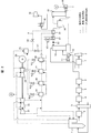
- FIG. 1 shows the basic configuration of a coal fired boiler system equipped with a CO2 recovery system.
- the flow of exhaust gas is indicated by a solid line
- the flow of steam / water is indicated by a broken line
- the flow of CO2 absorbent is indicated by a dotted line.
- the exhaust gas after burning in the pulverized coal-fired boiler 1 removes nitrogen oxides (hereinafter referred to as NOx) with a denitration device 2, heats the combustion air with the exhaust gas with an air heater 3, and recovers heat.
- the exhaust gas is cooled with a gas gas heater 4 (hereinafter referred to as heat recovery GGH), dust in the exhaust gas is removed with a dry electrostatic precipitator 5, and sulfur oxides (hereinafter referred to as SOx) are removed with a desulfurizer 6.
- the reheated gas gas heater 7 hereinafter reheated GGH heats the exhaust gas to prevent white smoke and exhausts it from the chimney 8.
- CO2 recovery leads exhaust gas from the downstream of the desulfurization device 6 to the CO2 recovery system.
- the exhaust gas contains a small amount of SOx and sulfuric acid gas in which SOx is oxidized, and these gases are removed by the NaOH spraying device 12 that sprays an alkaline solution in order to degrade the CO2 absorption solution.
- an alkanolamine-based aqueous solution is used as the CO2 absorbing solution.
- the absorption tower 13 makes the exhaust gas contact with the absorption liquid, absorbs CO 2, and the exhaust gas after absorption is returned before the reheating GGH 7 and exhausted from the chimney 8.
- the absorbing solution generates heat when absorbing CO2. Therefore, in order to absorb CO2 efficiently, the absorption liquid temperature is preferably low.
- the absorption liquid that has absorbed CO2 is heated by the liquid-liquid heat exchanger 14 and led to the regeneration tower 15 to desorb CO2 from the absorption liquid.
- the reboiler 16 for heating using the extracted steam from the steam turbine is provided.
- the temperature of the absorbing solution for desorbing CO2 varies depending on the type of absorbing solution.
- the desorbed gas of CO2 contains steam, it is dehumidified by the desorbed gas cooler 18 and compressed by the compressor 19 to be liquefied and recovered.
- the absorption liquid from which CO 2 has been desorbed by the regeneration tower 15 is cooled by the liquid-liquid heat exchanger 14 and further cooled to a temperature at which the absorption liquid cooler 17 absorbs CO 2, and then guided to the absorption tower 13.
- the water in the condenser 25 is sequentially heated by a first low-pressure feed water heater 26, a second low-pressure feed water heater 27, a third low-pressure feed water heater 28, and a fourth low-pressure feed water heater 29. It is heated with a feed water heater and led to a coal fired boiler 1 for heat recovery.
- the low pressure feed water heaters 26 to 29 heat the water from the condenser 25 using the heat of the extracted steam from the low pressure turbine 23. At that time, the extracted steam is condensed in the low-pressure feed water heaters 26 to 29 to become drain water.
- the drain water is extracted so that the water level is always constant, the drain water of the first low-pressure feed water heater 26 is returned to the condenser 25, and the drain water of the second low-pressure feed water heater 27 is the first low-pressure feed water heater.
- the drain water of the third low-pressure feed water heater 28 is returned to the second low-pressure feed water heater 27, and the drain water of the fourth low-pressure feed water heater 29 is returned to the third low-pressure feed water heater 28.
- Higher temperature extraction steam is required toward the downstream, and the water from the condenser is heated stepwise toward the downstream.
- the heat loss in the CO2 recovery system is heat removal by the NaOH cooling device 11, heat removal by the absorption liquid cooler 17, and heat removal by the desorption gas cooler 18.
- the present invention focuses on heat loss in the absorption liquid cooler 17 among them, and hereinafter, the present invention will be described with reference to examples.
- FIG. 2 shows a coal fired boiler system diagram equipped with the CO2 recovery system of the first embodiment.
- An absorption liquid cooler 31 for condensate heating is provided upstream of the absorption liquid cooler 17, the water in the condenser 25 is passed through, the lean liquid of the absorption liquid is removed, and heat is recovered to recover the first low pressure. Lead to feed water heater 26.
- the temperature of the lean liquid supply port of the absorption tower 13 is measured with a T1 thermometer 37.
- the temperature of the lean liquid at the position of the lean liquid supply port needs to be maintained at T1 '(for example, about 40 degrees) that is a temperature for absorbing CO2. Therefore, a flow rate adjusting valve V3 for adjusting the cooling water amount of the absorbing liquid cooler 17 is provided, and the temperature of the thermometer 37 is maintained at the CO2 absorption temperature T1 'by increasing or decreasing the cooling water amount.
- a flow rate adjustment valve V1 is provided between the condenser 25 and the first low-pressure feed water heater 26, the pipe a is branched from between the condenser 25 and the flow rate adjustment valve V1, and is used for heating the condensate via the on-off valve V2.
- the condensed water cooler 31 for condensate heating is further connected to the flow rate control valve V1 and the first low-pressure feed water heater 26. Further, steam is extracted from the low-pressure turbine 23 and led to the first low-pressure feed water heater 26. Meanwhile, an on-off valve VL1 was provided.
- the pressure in the first low-pressure feed water heater 26 is maintained at a predetermined pressure PL1 ', and the water temperature at the outlet of the first low-pressure feed water heater 26 is maintained.
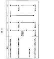
- Fig. 3 shows the operational diagram of the CO2 recovery system in the example.
- the flow control valve V1 is opened and the on-off valve V2 is closed, and the water in the condenser 25 is directly passed to the first low-pressure feed water heater 26.
- the on-off valve VL ⁇ b> 1 is open and heats water with steam from the low-pressure turbine 23.
- the CO2 absorption liquid is circulated between the absorption tower 13 and the regeneration tower 15, and the reboiler 16 starts heating the CO2 absorption liquid to absorb and desorb CO2. Adjust the temperature conditions for release. At that time, the flow rate adjustment valve V3 is adjusted so that the temperature of the T1 thermometer 37 becomes T1 '.
- the heat recovery in the condensate heating absorption liquid cooler 31 is started by opening the on-off valve V2 as operation (1-1) and closing the on-off valve VL1 as operation (1-2) to heat the first low-pressure feed water.
- the steam supply to the vessel 26 is stopped.
- the flow control valve V1 is closed.
- the operation 1-3 is preferably a slow operation.
- the flow rate adjusting valve V3 is controlled so that the temperature of the T1 thermometer 37 becomes T1 ', and is adjusted in the closing direction to suppress the cooling water amount of the absorbing liquid cooler 17 by the temperature drop of the lean liquid.
- the lean liquid temperature T1 supplied to the absorption tower 13 is controlled by the flow rate control valve V3 so that it becomes T1 ', and other operations are not required. If the boiler load increases, the amount of water from the condenser increases, so the flow control valve V3 is adjusted in the opening direction. On the other hand, if the boiler load decreases, the amount of water from the condenser decreases, the flow control valve V3 is adjusted in the closing direction.
- the absorption liquid cooling 17 in FIG. 2 can be deleted, and the control operation of the control valve V3 in FIG. 3 can be deleted. it can.
- the extracted steam led from the low-pressure turbine 23 to the second low-pressure feed water heater 27, the third low-pressure feed water heater 28, or the fourth low-pressure feed water heater 29 is supplied. It is also possible to shut off sequentially, and the power generation output can be improved by reducing the extracted steam from the low-pressure turbine 23.
- the lean liquid temperature at the outlet of the condensate heating absorption liquid cooler 31 is a temperature between the lean liquid temperature at the inlet of the condensate heating absorption liquid cooler 31 and the water temperature from the condenser, Extraction steam cannot be reduced unless the water is as hot as the subsequent stages of the low-pressure feed water heaters 26-29. Therefore, it is necessary to increase the temperature of the water from the condenser.
- Stopping the heat recovery at the condensate heating absorption liquid cooler 31 is as follows: operation (1-4): open flow control valve V1, operation (1-5): open / close valve V2: operation (1-6): open / close valve VL1 is opened in this order, and during that time, the flow rate control valve V3 controls T1 to be T1 ′.
- Example 2 of the present invention an example in which a heat pump is used to make the water from the condenser higher in temperature will be described.
- recovery system which provided the heat pump of Example 2 in FIG. 4 is shown.
- a condenser heater 46 is provided downstream of the condenser 25.
- the heat medium was circulated between the condensate heater 46 and the heat medium heating absorption liquid cooler 41 upstream of the absorption liquid cooler 17 to constitute a heat pump to exchange heat.
- the heat medium heating absorbent cooler 41 is equivalent to the condensate heating absorbent cooler 31 of FIG. Furthermore, a heat medium compressor 45 is provided downstream of the heat medium heating absorbent cooler 41 via a pipe b so that the heat medium is guided to the condensate heater 46. In the meantime, the heat medium compressor 45 was provided, and the heat medium was compressed to a high temperature to heat the water from the condensate of the condensate heater 46. Further, a pressure reducing valve 47 is provided downstream of the condensate heater 46 so that the heat medium is expanded to a low temperature, and the heat medium is heated by the heat medium heating absorbent cooler 41.
- FIG. 5A shows an operation method up to the maximum heat recovery of the CO2 recovery system provided with the heat pump of the embodiment and an operation diagram when the boiler load fluctuates.
- the flow rate control valve V3 is a water amount control valve that cools the lean liquid, and always controls the lean liquid temperature T1 to T1 '.
- the heat medium bypass valve V4 is opened and the on-off valve V5 is closed, and the water from the condenser is not subjected to heat exchange by the condensate heater 46, and is heated as it is in the first feed water.
- Guide to vessel 26 In the first to fourth feed water heaters 26 to 29, the on-off valve VL1, the on-off valve VL2, the on-off valve VL3, and the on-off valve VL4 are opened, respectively, and the water from the condenser is heated by the extraction steam from the low-pressure turbine. .
- the on-off valve V5 is opened as operation (2-1) so that the heat medium can be passed through the condensate heater 46.
- operation (2-2) the heat medium bypass valve V4 is slowly operated in the closing direction, the amount of the heat medium to the condensate heater 46 is increased, and finally the entire amount is passed.
- operation (2-3) the heat medium compressor 45 is started, and the heat medium is passed through the condensate heater 46.
- the minimum load is set, and the output of the heat medium compressor 45 is increased as operation (2-4) in accordance with the closing direction speed of the heat medium bypass valve V4.
- the operations (2-2) and (2-4) are preferably slow operations.
- the heat medium compressor 45 As the output of the heat medium compressor 45 increases, the heat medium is pressurized and the temperature rises, and the temperature of water from the condenser also rises due to heat exchange. As the temperature of the water from the condenser increases, heating in the first to fourth feed water heaters 26 to 29 becomes unnecessary, so that the supply of extracted steam from the low-pressure turbine can be shut off.
- the on-off valve VL4 is sequentially closed.
- the output of the generator 24 is improved by reducing the extracted steam from the low-pressure turbine.
- the amount of heat that can be recovered by the heat medium heating absorption liquid cooler 41 is the amount of heat when the lean liquid temperature at the outlet of the heat medium heating absorption liquid cooler 41 reaches T1 ′, and the absorption liquid cooler 17 is cooled. This is the amount of heat when water is not required, that is, when the flow control valve V3 is closed.
- the output of the heat medium compressor 45 at that time is the maximum output, and the operations (2-5) to (2-8) are finished when the maximum output is reached.
- FIG. 5B shows an operation diagram of the CO2 recovery system provided with the heat pump of the embodiment and the heat recovery stop.
- a heat recovery stop method from the condition that the heat medium compressor 45 has the maximum output, that is, the flow rate control valve V3 is closed and the heat recovery in the condensate heater becomes the maximum load is shown.
- the heat medium compressor 45 is lowered slowly from the maximum output to the minimum load. Meanwhile, the operation (2-14) to the operation (2-17), that is, the on-off valve VL4 to the on-off valve VL1 are sequentially opened from the closed state, and then the heat medium compressor 45 is stopped. Further, the open / close valve V5 is closed as operation (2-18), and the heat medium bypass valve V4 is opened as operation (2-19).
- Example 2 can make the water from a condenser into a high temperature with a heat pump, it supplies to the low-pressure feed water heater of the most downstream of a high temperature among a plurality of low-pressure feed water heaters in series. , The thermal efficiency of the boiler can be improved efficiently. Further, in the coal fired boiler system, a pipe branched in the middle of the condenser and the feed water heater is provided, and a valve is provided in the middle of the pipe to the most upstream feed water heater and the pipe to the condensate heater, respectively. Can be provided.
- Example 3 will be described.
- the increase in power generation efficiency by reducing the amount of extracted steam is effective in reducing the extracted steam of the low-pressure feed water heater on the downstream side, which has been improved.
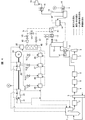
- FIG. 6 shows a system diagram of a coal-fired boiler equipped with a CO2 recovery system provided with a heat pump according to a third embodiment of the present invention.
- a branch was made downstream of the condenser 25, one of which led to the first low-pressure feed water heater 26, and an on-off valve V6 was provided therebetween.
- the other was provided with a condensate heater 46 via a flow rate control valve V7.
- the heat exchange between the condensate heater 46 and the heat medium heating absorption liquid cooler 41 is the same as that in FIG. 5 and constitutes a heat pump. Further, the heated water that passed through the condensate heater 46 was led to the inlet of the fourth low-pressure feed water heater 29.
- the water temperature when all of the heat quantity discarded in the absorption liquid cooler 17 is used for heating water from the condenser is about the water temperature at the inlet of the fourth low-pressure feed water heater 29, and
- the temperature of the extraction steam supplied to the fourth low-pressure feed water heater 29 is equal to or lower than the temperature.
- the water heated by the condensate heater 46 may be led to the inlet of the second low-pressure feed water heater 27 and the inlet of the third low-pressure feed water heater 28, but reduces the bleed steam of the low-pressure feed water heater on the downstream side. Is effective for improving the power generation efficiency, and the extraction steam is condensed in the low-pressure feed water heater, and the drain water level must be extracted and held. Therefore, the water heated by the condensate heater 46 is used. Is preferably introduced to the inlet of the fourth low-pressure feed water heater 29.
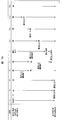
- FIG. 7A shows an operation method up to the maximum heat recovery of the CO2 recovery system provided with the heat pump of the embodiment and an operation diagram when the boiler load fluctuates.
- the flow rate control valve V3 is a water amount control valve that cools the lean liquid, and always controls the lean liquid temperature T1 to T1 '.
- the heat medium bypass valve V4 is opened, the on-off valve V5 is closed, and the on-off valve V6 is opened, and water from the condenser is directly guided to the first feed water heater 26.
- the on-off valve VL1, the on-off valve VL2, the on-off valve VL3, and the on-off valve VL4 are opened, respectively, and the water from the condenser is heated by the extraction steam from the low-pressure turbine. .
- the flow rate control valve V7 is opened, and as the operation (3-2), the on-off valve V6 is slowly operated in the closing direction, and the water from the condenser is Is passed through the condensate heater 46.
- the on-off valve V5 is opened so that the heat medium can be passed through the condensate heater 46.
- the heat medium bypass valve V4 is slowly operated in the closing direction, the amount of the heat medium to the condensate heater 46 is increased, and finally the entire amount of the heat medium is passed through.
- the heat medium compressor 45 is started, and the heat medium is passed through the condensate heater 46.
- the minimum load is set, and the output of the heat medium compressor 45 is increased as operation (3-6) in accordance with the closing direction speed of the heat medium bypass valve V4. Since the water from the condenser is not supplied to the first low-pressure feed water heater 26 when the on-off valve V6 is closed, the on-off valve VL1, on-off valve VL2, and on-off valve are operated as operation (3-7). VL3 is closed.
- the water from the condenser is recovered by the condenser heater 46 and the temperature rises as the output of the heat medium compressor 45 increases.
- the on-off valve VL4 is normally open, and the amount of extracted steam decreases as the water temperature increases.
- the operation (3-8) reduces the output of the heat medium compressor 45 and reduces the temperature of the heat medium to suppress overheating of the water.
- the amount of water from the condenser increases. Therefore, as operation (3-9), the output of the heat medium compressor 45 is increased and the temperature of the heat medium is increased to increase the amount of water heated. increase.
- the output change of the heat medium compressor 45 is a slow operation for the stable operation of the system.
- FIG. 7B shows an operation diagram of the heat recovery stop of the CO2 recovery system provided with the heat pump of the embodiment.
- a heat recovery stop method from the condition that the heat medium compressor 45 is at the maximum output, that is, the flow rate control valve V3 is closed and the heat recovery at the condensate heater becomes the maximum load is shown.
Landscapes
- Engineering & Computer Science (AREA)
- Chemical & Material Sciences (AREA)
- Combustion & Propulsion (AREA)
- Mechanical Engineering (AREA)
- General Engineering & Computer Science (AREA)
- General Chemical & Material Sciences (AREA)
- Analytical Chemistry (AREA)
- Oil, Petroleum & Natural Gas (AREA)
- Chemical Kinetics & Catalysis (AREA)
- Treating Waste Gases (AREA)
- Gas Separation By Absorption (AREA)
- Carbon And Carbon Compounds (AREA)
- Chimneys And Flues (AREA)
Abstract
Dans un système de collecte de CO2 utilisant un liquide absorbant, en se concentrant sur la chaleur qui présente une petite différence de température et qui est difficile à utiliser efficacement, on obtient une utilisation efficace de la chaleur du système de collecte de CO2 en utilisant le liquide absorbant. En se concentrant sur la quantité de chaleur dans laquelle la température d'un liquide pauvre obtenu après l'échange de chaleur entre un liquide absorbant (liquide pauvre), duquel le CO2 est désorbé, et un liquide absorbant (liquide riche) dans lequel le CO2 est absorbé, est diminuée jusqu'à la température à laquelle le CO2 est absorbé, l'eau provenant d'un condenseur est utilisée comme réfrigérant du liquide pauvre. De plus, la différence de température entre l'eau du condenseur et le liquide pauvre obtenue après l'échange de chaleur entre le liquide pauvre et le liquide riche est créée par une pompe à chaleur qui comprime et dilate la substance à l'aide d'une autre substance, ce qui crée un échange de chaleur facile. L'eau du condenseur est chauffée successivement en utilisant un courant latéral de vapeur d'une turbine à vapeur grâce à une pluralité de chaudières d'alimentation en eau basse pression raccordées en série. L'eau du condenseur est partagée en deux branches, et une est fournie à un orifice d'entrée de la chaudière d'alimentation en eau basse pression sur le courant le plus haut, tandis que l'autre est fournie à un orifice d'entrée de la chaudière d'alimentation en eau basse pression du courant le plus bas de la pluralité de chaudières d'alimentation en eau basse pression après avoir été soumises au traitement à haute température à l'aide de la pompe à chaleur.
Applications Claiming Priority (2)
| Application Number | Priority Date | Filing Date | Title |
|---|---|---|---|
| JP2011031627A JP5468562B2 (ja) | 2011-02-17 | 2011-02-17 | 二酸化炭素回収システムを備えた石炭焚きボイラシステム |
| JP2011-031627 | 2011-02-17 |
Publications (1)
| Publication Number | Publication Date |
|---|---|
| WO2012111495A1 true WO2012111495A1 (fr) | 2012-08-23 |
Family
ID=46672421
Family Applications (1)
| Application Number | Title | Priority Date | Filing Date |
|---|---|---|---|
| PCT/JP2012/052808 Ceased WO2012111495A1 (fr) | 2011-02-17 | 2012-02-08 | Système de chaudière au charbon doté d'un système de collecte de dioxyde de carbone |
Country Status (2)
| Country | Link |
|---|---|
| JP (1) | JP5468562B2 (fr) |
| WO (1) | WO2012111495A1 (fr) |
Cited By (12)
| Publication number | Priority date | Publication date | Assignee | Title |
|---|---|---|---|---|
| FR3005143A1 (fr) * | 2013-04-25 | 2014-10-31 | Pyraine | Installation thermique de production d'electricite par combustion |
| US8920548B2 (en) | 2012-01-06 | 2014-12-30 | Babcock-Hitachi K.K. | CO2 capture system by chemical absorption |
| NL2011617C2 (nl) * | 2013-10-15 | 2015-04-16 | Kea Consult B V | Systeem en werkwijze voor winning van warmte uit een gasstroom. |
| CN104534439A (zh) * | 2015-01-07 | 2015-04-22 | 西安热工研究院有限公司 | 余热梯级利用的低能级抽汽间接加热暖风器系统及方法 |
| CN107355266A (zh) * | 2017-06-14 | 2017-11-17 | 西安热工研究院有限公司 | 一种利用二氧化碳逆循环实现完全热电解耦的热电系统 |
| CN111871159A (zh) * | 2020-07-15 | 2020-11-03 | 中石化南京化工研究院有限公司 | 一种膜分离耦合醇胺溶液捕集烟气co2装置和方法 |
| CN112933894A (zh) * | 2021-04-02 | 2021-06-11 | 中国华电科工集团有限公司 | 一种二氧化碳捕集与低加凝结水耦合系统 |
| WO2022125717A1 (fr) * | 2020-12-09 | 2022-06-16 | Arizona Board Of Regents On Behalf Of Arizona State University | Système et procédé de capture efficace de dioxyde de carbone |
| CN114934825A (zh) * | 2022-05-25 | 2022-08-23 | 西安热工研究院有限公司 | 一种与煤电机组耦合的二氧化碳储能系统及方法 |
| CN115031221A (zh) * | 2022-05-24 | 2022-09-09 | 湖北工业大学 | 一种集成槽式太阳能聚光分频集热器的燃煤脱碳发电系统及方法 |
| CN115888330A (zh) * | 2022-11-08 | 2023-04-04 | 西安交通大学 | 一种烟气能量利用的低碳排放的燃煤系统及控制方法 |
| CN116136184A (zh) * | 2021-11-18 | 2023-05-19 | 国家能源投资集团有限责任公司 | 多工质热电调峰系统及其运行方法 |
Families Citing this family (7)
| Publication number | Priority date | Publication date | Assignee | Title |
|---|---|---|---|---|
| CN102895843B (zh) * | 2012-09-24 | 2015-02-25 | 天津大学 | 一种采用超高温热泵回收利用mdea脱碳工艺余热的系统 |
| JP5914300B2 (ja) * | 2012-11-08 | 2016-05-11 | 株式会社日立製作所 | Co2固体吸着材システム |
| CN104420854A (zh) * | 2013-09-05 | 2015-03-18 | 天津凯德实业有限公司 | 煤层气采集设备 |
| JP6163994B2 (ja) * | 2013-09-18 | 2017-07-19 | 株式会社Ihi | 酸素燃焼ボイラの排ガスクーラ蒸気発生防止装置 |
| JP6737611B2 (ja) | 2016-03-25 | 2020-08-12 | 三菱日立パワーシステムズ株式会社 | 火力発電システム及び火力発電システムの制御方法 |
| JP7356345B2 (ja) * | 2019-12-27 | 2023-10-04 | 三菱重工業株式会社 | 排気ガス処理設備、及びガスタービンプラント |
| WO2024111523A1 (fr) * | 2022-11-25 | 2024-05-30 | 三菱重工業株式会社 | Système de récupération de dioxyde de carbone et procédé de récupération de dioxyde de carbone |
Citations (4)
| Publication number | Priority date | Publication date | Assignee | Title |
|---|---|---|---|---|
| JP2002013808A (ja) * | 2000-06-28 | 2002-01-18 | Denso Corp | ヒートポンプ式温水器 |
| JP2002364801A (ja) * | 2001-06-05 | 2002-12-18 | Nkk Corp | 廃熱利用システム |
| JP2008157511A (ja) * | 2006-12-22 | 2008-07-10 | Chugoku Electric Power Co Inc:The | 軸受冷却水熱回収装置 |
| JP2010088982A (ja) * | 2008-10-06 | 2010-04-22 | Toshiba Corp | 二酸化炭素回収システム |
Family Cites Families (2)
| Publication number | Priority date | Publication date | Assignee | Title |
|---|---|---|---|---|
| JPH0779950B2 (ja) * | 1989-12-25 | 1995-08-30 | 三菱重工業株式会社 | 燃焼排ガス中のco▲下2▼の除去方法 |
| JPH0490496A (ja) * | 1990-08-03 | 1992-03-24 | Mitsubishi Heavy Ind Ltd | 蒸気タービンプラントの復水装置 |
-
2011
- 2011-02-17 JP JP2011031627A patent/JP5468562B2/ja not_active Expired - Fee Related
-
2012
- 2012-02-08 WO PCT/JP2012/052808 patent/WO2012111495A1/fr not_active Ceased
Patent Citations (4)
| Publication number | Priority date | Publication date | Assignee | Title |
|---|---|---|---|---|
| JP2002013808A (ja) * | 2000-06-28 | 2002-01-18 | Denso Corp | ヒートポンプ式温水器 |
| JP2002364801A (ja) * | 2001-06-05 | 2002-12-18 | Nkk Corp | 廃熱利用システム |
| JP2008157511A (ja) * | 2006-12-22 | 2008-07-10 | Chugoku Electric Power Co Inc:The | 軸受冷却水熱回収装置 |
| JP2010088982A (ja) * | 2008-10-06 | 2010-04-22 | Toshiba Corp | 二酸化炭素回収システム |
Cited By (15)
| Publication number | Priority date | Publication date | Assignee | Title |
|---|---|---|---|---|
| US8920548B2 (en) | 2012-01-06 | 2014-12-30 | Babcock-Hitachi K.K. | CO2 capture system by chemical absorption |
| FR3005143A1 (fr) * | 2013-04-25 | 2014-10-31 | Pyraine | Installation thermique de production d'electricite par combustion |
| NL2011617C2 (nl) * | 2013-10-15 | 2015-04-16 | Kea Consult B V | Systeem en werkwijze voor winning van warmte uit een gasstroom. |
| CN104534439A (zh) * | 2015-01-07 | 2015-04-22 | 西安热工研究院有限公司 | 余热梯级利用的低能级抽汽间接加热暖风器系统及方法 |
| CN107355266A (zh) * | 2017-06-14 | 2017-11-17 | 西安热工研究院有限公司 | 一种利用二氧化碳逆循环实现完全热电解耦的热电系统 |
| CN111871159A (zh) * | 2020-07-15 | 2020-11-03 | 中石化南京化工研究院有限公司 | 一种膜分离耦合醇胺溶液捕集烟气co2装置和方法 |
| US12521670B2 (en) * | 2020-12-09 | 2026-01-13 | Arizona Board Of Regents On Behalf Of Arizona State University | System and method for efficient carbon dioxide capture |
| WO2022125717A1 (fr) * | 2020-12-09 | 2022-06-16 | Arizona Board Of Regents On Behalf Of Arizona State University | Système et procédé de capture efficace de dioxyde de carbone |
| US12533624B2 (en) | 2020-12-09 | 2026-01-27 | Arizona Board Of Regents On Behalf Of Arizona State University | System and method for resource-efficient carbon dioxide capture |
| US12528042B2 (en) | 2020-12-09 | 2026-01-20 | Arizona Board Of Regents On Behalf Of Arizona State University | Device, system, and method for carbon dioxide capture in humid conditions |
| CN112933894A (zh) * | 2021-04-02 | 2021-06-11 | 中国华电科工集团有限公司 | 一种二氧化碳捕集与低加凝结水耦合系统 |
| CN116136184A (zh) * | 2021-11-18 | 2023-05-19 | 国家能源投资集团有限责任公司 | 多工质热电调峰系统及其运行方法 |
| CN115031221A (zh) * | 2022-05-24 | 2022-09-09 | 湖北工业大学 | 一种集成槽式太阳能聚光分频集热器的燃煤脱碳发电系统及方法 |
| CN114934825A (zh) * | 2022-05-25 | 2022-08-23 | 西安热工研究院有限公司 | 一种与煤电机组耦合的二氧化碳储能系统及方法 |
| CN115888330A (zh) * | 2022-11-08 | 2023-04-04 | 西安交通大学 | 一种烟气能量利用的低碳排放的燃煤系统及控制方法 |
Also Published As
| Publication number | Publication date |
|---|---|
| JP2012167918A (ja) | 2012-09-06 |
| JP5468562B2 (ja) | 2014-04-09 |
Similar Documents
| Publication | Publication Date | Title |
|---|---|---|
| JP5468562B2 (ja) | 二酸化炭素回収システムを備えた石炭焚きボイラシステム | |
| CN114768488B (zh) | 一种燃煤机组烟气二氧化碳捕集系统 | |
| US9856755B2 (en) | Thermal integration of a carbon dioxide capture and compression unit with a steam or combined cycle plant | |
| AU2019261031B2 (en) | Plant and combustion exhaust gas processing method | |
| US20130312386A1 (en) | Combined cycle power plant with co2 capture plant | |
| JP7330718B2 (ja) | ガスタービンプラント、及びその排出二酸化炭素回収方法 | |
| US12409411B2 (en) | Exhaust gas processing equipment and gas turbine plant | |
| WO2012164856A1 (fr) | Procédé et appareil de récupération du co2 | |
| JP7412102B2 (ja) | ガスタービンプラント | |
| JP2012158996A (ja) | 二酸化炭素分離回収装置を備えた火力発電システム | |
| CA2830623C (fr) | Systeme de materiau adsorbant de co2 solide | |
| US20200054989A1 (en) | Carbon dioxide recovery system and carbon dioxide recovery method | |
| AU2013313605B2 (en) | Heat recovery system and heat recovery method | |
| WO2014129391A1 (fr) | Procédé et système de récupération de co2 | |
| JP7720949B2 (ja) | ガスタービンプラント | |
| JP2012137269A (ja) | 石炭火力発電プラント及び石炭火力発電プラントの制御方法 | |
| AU2022380470A1 (en) | Carbon capture system and method with exhaust gas recirculation | |
| CN210768960U (zh) | 带捕碳装置的燃煤发电系统 | |
| US20250345746A1 (en) | Exhaust gas processing equipment and gas turbine plant | |
| WO2025136366A1 (fr) | Système et procédé de capture de carbone à l'aide d'une eau chauffée provenant d'un générateur de vapeur à récupération de chaleur |
Legal Events
| Date | Code | Title | Description |
|---|---|---|---|
| 121 | Ep: the epo has been informed by wipo that ep was designated in this application |
Ref document number: 12747452 Country of ref document: EP Kind code of ref document: A1 |
|
| NENP | Non-entry into the national phase |
Ref country code: DE |
|
| 122 | Ep: pct application non-entry in european phase |
Ref document number: 12747452 Country of ref document: EP Kind code of ref document: A1 |