WO2012114430A1 - Dispositif de commande de conduite de véhicule hybride - Google Patents
Dispositif de commande de conduite de véhicule hybride Download PDFInfo
- Publication number
- WO2012114430A1 WO2012114430A1 PCT/JP2011/053690 JP2011053690W WO2012114430A1 WO 2012114430 A1 WO2012114430 A1 WO 2012114430A1 JP 2011053690 W JP2011053690 W JP 2011053690W WO 2012114430 A1 WO2012114430 A1 WO 2012114430A1
- Authority
- WO
- WIPO (PCT)
- Prior art keywords
- power
- target
- motor generator
- battery
- engine
- Prior art date
- Legal status (The legal status is an assumption and is not a legal conclusion. Google has not performed a legal analysis and makes no representation as to the accuracy of the status listed.)
- Ceased
Links
Images


Classifications
-
- B—PERFORMING OPERATIONS; TRANSPORTING
- B60—VEHICLES IN GENERAL
- B60L—PROPULSION OF ELECTRICALLY-PROPELLED VEHICLES; SUPPLYING ELECTRIC POWER FOR AUXILIARY EQUIPMENT OF ELECTRICALLY-PROPELLED VEHICLES; ELECTRODYNAMIC BRAKE SYSTEMS FOR VEHICLES IN GENERAL; MAGNETIC SUSPENSION OR LEVITATION FOR VEHICLES; MONITORING OPERATING VARIABLES OF ELECTRICALLY-PROPELLED VEHICLES; ELECTRIC SAFETY DEVICES FOR ELECTRICALLY-PROPELLED VEHICLES
- B60L58/00—Methods or circuit arrangements for monitoring or controlling batteries or fuel cells, specially adapted for electric vehicles
- B60L58/10—Methods or circuit arrangements for monitoring or controlling batteries or fuel cells, specially adapted for electric vehicles for monitoring or controlling batteries
- B60L58/12—Methods or circuit arrangements for monitoring or controlling batteries or fuel cells, specially adapted for electric vehicles for monitoring or controlling batteries responding to state of charge [SoC]
- B60L58/15—Preventing overcharging
-
- B—PERFORMING OPERATIONS; TRANSPORTING
- B60—VEHICLES IN GENERAL
- B60K—ARRANGEMENT OR MOUNTING OF PROPULSION UNITS OR OF TRANSMISSIONS IN VEHICLES; ARRANGEMENT OR MOUNTING OF PLURAL DIVERSE PRIME-MOVERS IN VEHICLES; AUXILIARY DRIVES FOR VEHICLES; INSTRUMENTATION OR DASHBOARDS FOR VEHICLES; ARRANGEMENTS IN CONNECTION WITH COOLING, AIR INTAKE, GAS EXHAUST OR FUEL SUPPLY OF PROPULSION UNITS IN VEHICLES
- B60K6/00—Arrangement or mounting of plural diverse prime-movers for mutual or common propulsion, e.g. hybrid propulsion systems comprising electric motors and internal combustion engines
- B60K6/20—Arrangement or mounting of plural diverse prime-movers for mutual or common propulsion, e.g. hybrid propulsion systems comprising electric motors and internal combustion engines the prime-movers consisting of electric motors and internal combustion engines, e.g. HEVs
- B60K6/22—Arrangement or mounting of plural diverse prime-movers for mutual or common propulsion, e.g. hybrid propulsion systems comprising electric motors and internal combustion engines the prime-movers consisting of electric motors and internal combustion engines, e.g. HEVs characterised by apparatus, components or means specially adapted for HEVs
- B60K6/36—Arrangement or mounting of plural diverse prime-movers for mutual or common propulsion, e.g. hybrid propulsion systems comprising electric motors and internal combustion engines the prime-movers consisting of electric motors and internal combustion engines, e.g. HEVs characterised by apparatus, components or means specially adapted for HEVs characterised by the transmission gearings
- B60K6/365—Arrangement or mounting of plural diverse prime-movers for mutual or common propulsion, e.g. hybrid propulsion systems comprising electric motors and internal combustion engines the prime-movers consisting of electric motors and internal combustion engines, e.g. HEVs characterised by apparatus, components or means specially adapted for HEVs characterised by the transmission gearings with the gears having orbital motion
-
- B—PERFORMING OPERATIONS; TRANSPORTING
- B60—VEHICLES IN GENERAL
- B60K—ARRANGEMENT OR MOUNTING OF PROPULSION UNITS OR OF TRANSMISSIONS IN VEHICLES; ARRANGEMENT OR MOUNTING OF PLURAL DIVERSE PRIME-MOVERS IN VEHICLES; AUXILIARY DRIVES FOR VEHICLES; INSTRUMENTATION OR DASHBOARDS FOR VEHICLES; ARRANGEMENTS IN CONNECTION WITH COOLING, AIR INTAKE, GAS EXHAUST OR FUEL SUPPLY OF PROPULSION UNITS IN VEHICLES
- B60K6/00—Arrangement or mounting of plural diverse prime-movers for mutual or common propulsion, e.g. hybrid propulsion systems comprising electric motors and internal combustion engines
- B60K6/20—Arrangement or mounting of plural diverse prime-movers for mutual or common propulsion, e.g. hybrid propulsion systems comprising electric motors and internal combustion engines the prime-movers consisting of electric motors and internal combustion engines, e.g. HEVs
- B60K6/42—Arrangement or mounting of plural diverse prime-movers for mutual or common propulsion, e.g. hybrid propulsion systems comprising electric motors and internal combustion engines the prime-movers consisting of electric motors and internal combustion engines, e.g. HEVs characterised by the architecture of the hybrid electric vehicle
- B60K6/44—Series-parallel type
- B60K6/445—Differential gearing distribution type
-
- B—PERFORMING OPERATIONS; TRANSPORTING
- B60—VEHICLES IN GENERAL
- B60L—PROPULSION OF ELECTRICALLY-PROPELLED VEHICLES; SUPPLYING ELECTRIC POWER FOR AUXILIARY EQUIPMENT OF ELECTRICALLY-PROPELLED VEHICLES; ELECTRODYNAMIC BRAKE SYSTEMS FOR VEHICLES IN GENERAL; MAGNETIC SUSPENSION OR LEVITATION FOR VEHICLES; MONITORING OPERATING VARIABLES OF ELECTRICALLY-PROPELLED VEHICLES; ELECTRIC SAFETY DEVICES FOR ELECTRICALLY-PROPELLED VEHICLES
- B60L15/00—Methods, circuits, or devices for controlling the traction-motor speed of electrically-propelled vehicles
- B60L15/02—Methods, circuits, or devices for controlling the traction-motor speed of electrically-propelled vehicles characterised by the form of the current used in the control circuit
-
- B—PERFORMING OPERATIONS; TRANSPORTING
- B60—VEHICLES IN GENERAL
- B60L—PROPULSION OF ELECTRICALLY-PROPELLED VEHICLES; SUPPLYING ELECTRIC POWER FOR AUXILIARY EQUIPMENT OF ELECTRICALLY-PROPELLED VEHICLES; ELECTRODYNAMIC BRAKE SYSTEMS FOR VEHICLES IN GENERAL; MAGNETIC SUSPENSION OR LEVITATION FOR VEHICLES; MONITORING OPERATING VARIABLES OF ELECTRICALLY-PROPELLED VEHICLES; ELECTRIC SAFETY DEVICES FOR ELECTRICALLY-PROPELLED VEHICLES
- B60L50/00—Electric propulsion with power supplied within the vehicle
- B60L50/50—Electric propulsion with power supplied within the vehicle using propulsion power supplied by batteries or fuel cells
- B60L50/60—Electric propulsion with power supplied within the vehicle using propulsion power supplied by batteries or fuel cells using power supplied by batteries
- B60L50/61—Electric propulsion with power supplied within the vehicle using propulsion power supplied by batteries or fuel cells using power supplied by batteries by batteries charged by engine-driven generators, e.g. series hybrid electric vehicles
-
- B—PERFORMING OPERATIONS; TRANSPORTING
- B60—VEHICLES IN GENERAL
- B60L—PROPULSION OF ELECTRICALLY-PROPELLED VEHICLES; SUPPLYING ELECTRIC POWER FOR AUXILIARY EQUIPMENT OF ELECTRICALLY-PROPELLED VEHICLES; ELECTRODYNAMIC BRAKE SYSTEMS FOR VEHICLES IN GENERAL; MAGNETIC SUSPENSION OR LEVITATION FOR VEHICLES; MONITORING OPERATING VARIABLES OF ELECTRICALLY-PROPELLED VEHICLES; ELECTRIC SAFETY DEVICES FOR ELECTRICALLY-PROPELLED VEHICLES
- B60L58/00—Methods or circuit arrangements for monitoring or controlling batteries or fuel cells, specially adapted for electric vehicles
- B60L58/10—Methods or circuit arrangements for monitoring or controlling batteries or fuel cells, specially adapted for electric vehicles for monitoring or controlling batteries
- B60L58/12—Methods or circuit arrangements for monitoring or controlling batteries or fuel cells, specially adapted for electric vehicles for monitoring or controlling batteries responding to state of charge [SoC]
- B60L58/13—Maintaining the SoC within a determined range
-
- B—PERFORMING OPERATIONS; TRANSPORTING
- B60—VEHICLES IN GENERAL
- B60W—CONJOINT CONTROL OF VEHICLE SUB-UNITS OF DIFFERENT TYPE OR DIFFERENT FUNCTION; CONTROL SYSTEMS SPECIALLY ADAPTED FOR HYBRID VEHICLES; ROAD VEHICLE DRIVE CONTROL SYSTEMS FOR PURPOSES NOT RELATED TO THE CONTROL OF A PARTICULAR SUB-UNIT
- B60W10/00—Conjoint control of vehicle sub-units of different type or different function
- B60W10/04—Conjoint control of vehicle sub-units of different type or different function including control of propulsion units
- B60W10/06—Conjoint control of vehicle sub-units of different type or different function including control of propulsion units including control of combustion engines
-
- B—PERFORMING OPERATIONS; TRANSPORTING
- B60—VEHICLES IN GENERAL
- B60W—CONJOINT CONTROL OF VEHICLE SUB-UNITS OF DIFFERENT TYPE OR DIFFERENT FUNCTION; CONTROL SYSTEMS SPECIALLY ADAPTED FOR HYBRID VEHICLES; ROAD VEHICLE DRIVE CONTROL SYSTEMS FOR PURPOSES NOT RELATED TO THE CONTROL OF A PARTICULAR SUB-UNIT
- B60W10/00—Conjoint control of vehicle sub-units of different type or different function
- B60W10/04—Conjoint control of vehicle sub-units of different type or different function including control of propulsion units
- B60W10/08—Conjoint control of vehicle sub-units of different type or different function including control of propulsion units including control of electric propulsion units, e.g. motors or generators
-
- B—PERFORMING OPERATIONS; TRANSPORTING
- B60—VEHICLES IN GENERAL
- B60W—CONJOINT CONTROL OF VEHICLE SUB-UNITS OF DIFFERENT TYPE OR DIFFERENT FUNCTION; CONTROL SYSTEMS SPECIALLY ADAPTED FOR HYBRID VEHICLES; ROAD VEHICLE DRIVE CONTROL SYSTEMS FOR PURPOSES NOT RELATED TO THE CONTROL OF A PARTICULAR SUB-UNIT
- B60W10/00—Conjoint control of vehicle sub-units of different type or different function
- B60W10/24—Conjoint control of vehicle sub-units of different type or different function including control of energy storage means
- B60W10/26—Conjoint control of vehicle sub-units of different type or different function including control of energy storage means for electrical energy, e.g. batteries or capacitors
-
- B—PERFORMING OPERATIONS; TRANSPORTING
- B60—VEHICLES IN GENERAL
- B60W—CONJOINT CONTROL OF VEHICLE SUB-UNITS OF DIFFERENT TYPE OR DIFFERENT FUNCTION; CONTROL SYSTEMS SPECIALLY ADAPTED FOR HYBRID VEHICLES; ROAD VEHICLE DRIVE CONTROL SYSTEMS FOR PURPOSES NOT RELATED TO THE CONTROL OF A PARTICULAR SUB-UNIT
- B60W20/00—Control systems specially adapted for hybrid vehicles
- B60W20/10—Controlling the power contribution of each of the prime movers to meet required power demand
- B60W20/13—Controlling the power contribution of each of the prime movers to meet required power demand in order to stay within battery power input or output limits; in order to prevent overcharging or battery depletion
-
- B—PERFORMING OPERATIONS; TRANSPORTING
- B60—VEHICLES IN GENERAL
- B60W—CONJOINT CONTROL OF VEHICLE SUB-UNITS OF DIFFERENT TYPE OR DIFFERENT FUNCTION; CONTROL SYSTEMS SPECIALLY ADAPTED FOR HYBRID VEHICLES; ROAD VEHICLE DRIVE CONTROL SYSTEMS FOR PURPOSES NOT RELATED TO THE CONTROL OF A PARTICULAR SUB-UNIT
- B60W30/00—Purposes of road vehicle drive control systems not related to the control of a particular sub-unit, e.g. of systems using conjoint control of vehicle sub-units
- B60W30/18—Propelling the vehicle
- B60W30/188—Controlling power parameters of the driveline, e.g. determining the required power
- B60W30/1882—Controlling power parameters of the driveline, e.g. determining the required power characterised by the working point of the engine, e.g. by using engine output chart
-
- B—PERFORMING OPERATIONS; TRANSPORTING
- B60—VEHICLES IN GENERAL
- B60L—PROPULSION OF ELECTRICALLY-PROPELLED VEHICLES; SUPPLYING ELECTRIC POWER FOR AUXILIARY EQUIPMENT OF ELECTRICALLY-PROPELLED VEHICLES; ELECTRODYNAMIC BRAKE SYSTEMS FOR VEHICLES IN GENERAL; MAGNETIC SUSPENSION OR LEVITATION FOR VEHICLES; MONITORING OPERATING VARIABLES OF ELECTRICALLY-PROPELLED VEHICLES; ELECTRIC SAFETY DEVICES FOR ELECTRICALLY-PROPELLED VEHICLES
- B60L2240/00—Control parameters of input or output; Target parameters
- B60L2240/40—Drive Train control parameters
- B60L2240/54—Drive Train control parameters related to batteries
- B60L2240/545—Temperature
-
- B—PERFORMING OPERATIONS; TRANSPORTING
- B60—VEHICLES IN GENERAL
- B60W—CONJOINT CONTROL OF VEHICLE SUB-UNITS OF DIFFERENT TYPE OR DIFFERENT FUNCTION; CONTROL SYSTEMS SPECIALLY ADAPTED FOR HYBRID VEHICLES; ROAD VEHICLE DRIVE CONTROL SYSTEMS FOR PURPOSES NOT RELATED TO THE CONTROL OF A PARTICULAR SUB-UNIT
- B60W2510/00—Input parameters relating to a particular sub-units
- B60W2510/24—Energy storage means
- B60W2510/242—Energy storage means for electrical energy
- B60W2510/244—Charge state
-
- B—PERFORMING OPERATIONS; TRANSPORTING
- B60—VEHICLES IN GENERAL
- B60W—CONJOINT CONTROL OF VEHICLE SUB-UNITS OF DIFFERENT TYPE OR DIFFERENT FUNCTION; CONTROL SYSTEMS SPECIALLY ADAPTED FOR HYBRID VEHICLES; ROAD VEHICLE DRIVE CONTROL SYSTEMS FOR PURPOSES NOT RELATED TO THE CONTROL OF A PARTICULAR SUB-UNIT
- B60W2520/00—Input parameters relating to overall vehicle dynamics
- B60W2520/10—Longitudinal speed
-
- B—PERFORMING OPERATIONS; TRANSPORTING
- B60—VEHICLES IN GENERAL
- B60W—CONJOINT CONTROL OF VEHICLE SUB-UNITS OF DIFFERENT TYPE OR DIFFERENT FUNCTION; CONTROL SYSTEMS SPECIALLY ADAPTED FOR HYBRID VEHICLES; ROAD VEHICLE DRIVE CONTROL SYSTEMS FOR PURPOSES NOT RELATED TO THE CONTROL OF A PARTICULAR SUB-UNIT
- B60W2540/00—Input parameters relating to occupants
- B60W2540/10—Accelerator pedal position
-
- Y—GENERAL TAGGING OF NEW TECHNOLOGICAL DEVELOPMENTS; GENERAL TAGGING OF CROSS-SECTIONAL TECHNOLOGIES SPANNING OVER SEVERAL SECTIONS OF THE IPC; TECHNICAL SUBJECTS COVERED BY FORMER USPC CROSS-REFERENCE ART COLLECTIONS [XRACs] AND DIGESTS
- Y02—TECHNOLOGIES OR APPLICATIONS FOR MITIGATION OR ADAPTATION AGAINST CLIMATE CHANGE
- Y02T—CLIMATE CHANGE MITIGATION TECHNOLOGIES RELATED TO TRANSPORTATION
- Y02T10/00—Road transport of goods or passengers
- Y02T10/10—Internal combustion engine [ICE] based vehicles
- Y02T10/40—Engine management systems
-
- Y—GENERAL TAGGING OF NEW TECHNOLOGICAL DEVELOPMENTS; GENERAL TAGGING OF CROSS-SECTIONAL TECHNOLOGIES SPANNING OVER SEVERAL SECTIONS OF THE IPC; TECHNICAL SUBJECTS COVERED BY FORMER USPC CROSS-REFERENCE ART COLLECTIONS [XRACs] AND DIGESTS
- Y02—TECHNOLOGIES OR APPLICATIONS FOR MITIGATION OR ADAPTATION AGAINST CLIMATE CHANGE
- Y02T—CLIMATE CHANGE MITIGATION TECHNOLOGIES RELATED TO TRANSPORTATION
- Y02T10/00—Road transport of goods or passengers
- Y02T10/60—Other road transportation technologies with climate change mitigation effect
- Y02T10/62—Hybrid vehicles
-
- Y—GENERAL TAGGING OF NEW TECHNOLOGICAL DEVELOPMENTS; GENERAL TAGGING OF CROSS-SECTIONAL TECHNOLOGIES SPANNING OVER SEVERAL SECTIONS OF THE IPC; TECHNICAL SUBJECTS COVERED BY FORMER USPC CROSS-REFERENCE ART COLLECTIONS [XRACs] AND DIGESTS
- Y02—TECHNOLOGIES OR APPLICATIONS FOR MITIGATION OR ADAPTATION AGAINST CLIMATE CHANGE
- Y02T—CLIMATE CHANGE MITIGATION TECHNOLOGIES RELATED TO TRANSPORTATION
- Y02T10/00—Road transport of goods or passengers
- Y02T10/60—Other road transportation technologies with climate change mitigation effect
- Y02T10/64—Electric machine technologies in electromobility
-
- Y—GENERAL TAGGING OF NEW TECHNOLOGICAL DEVELOPMENTS; GENERAL TAGGING OF CROSS-SECTIONAL TECHNOLOGIES SPANNING OVER SEVERAL SECTIONS OF THE IPC; TECHNICAL SUBJECTS COVERED BY FORMER USPC CROSS-REFERENCE ART COLLECTIONS [XRACs] AND DIGESTS
- Y02—TECHNOLOGIES OR APPLICATIONS FOR MITIGATION OR ADAPTATION AGAINST CLIMATE CHANGE
- Y02T—CLIMATE CHANGE MITIGATION TECHNOLOGIES RELATED TO TRANSPORTATION
- Y02T10/00—Road transport of goods or passengers
- Y02T10/60—Other road transportation technologies with climate change mitigation effect
- Y02T10/70—Energy storage systems for electromobility, e.g. batteries
-
- Y—GENERAL TAGGING OF NEW TECHNOLOGICAL DEVELOPMENTS; GENERAL TAGGING OF CROSS-SECTIONAL TECHNOLOGIES SPANNING OVER SEVERAL SECTIONS OF THE IPC; TECHNICAL SUBJECTS COVERED BY FORMER USPC CROSS-REFERENCE ART COLLECTIONS [XRACs] AND DIGESTS
- Y02—TECHNOLOGIES OR APPLICATIONS FOR MITIGATION OR ADAPTATION AGAINST CLIMATE CHANGE
- Y02T—CLIMATE CHANGE MITIGATION TECHNOLOGIES RELATED TO TRANSPORTATION
- Y02T10/00—Road transport of goods or passengers
- Y02T10/60—Other road transportation technologies with climate change mitigation effect
- Y02T10/7072—Electromobility specific charging systems or methods for batteries, ultracapacitors, supercapacitors or double-layer capacitors
-
- Y—GENERAL TAGGING OF NEW TECHNOLOGICAL DEVELOPMENTS; GENERAL TAGGING OF CROSS-SECTIONAL TECHNOLOGIES SPANNING OVER SEVERAL SECTIONS OF THE IPC; TECHNICAL SUBJECTS COVERED BY FORMER USPC CROSS-REFERENCE ART COLLECTIONS [XRACs] AND DIGESTS
- Y02—TECHNOLOGIES OR APPLICATIONS FOR MITIGATION OR ADAPTATION AGAINST CLIMATE CHANGE
- Y02T—CLIMATE CHANGE MITIGATION TECHNOLOGIES RELATED TO TRANSPORTATION
- Y02T10/00—Road transport of goods or passengers
- Y02T10/80—Technologies aiming to reduce greenhouse gasses emissions common to all road transportation technologies
- Y02T10/84—Data processing systems or methods, management, administration
-
- Y—GENERAL TAGGING OF NEW TECHNOLOGICAL DEVELOPMENTS; GENERAL TAGGING OF CROSS-SECTIONAL TECHNOLOGIES SPANNING OVER SEVERAL SECTIONS OF THE IPC; TECHNICAL SUBJECTS COVERED BY FORMER USPC CROSS-REFERENCE ART COLLECTIONS [XRACs] AND DIGESTS
- Y02—TECHNOLOGIES OR APPLICATIONS FOR MITIGATION OR ADAPTATION AGAINST CLIMATE CHANGE
- Y02T—CLIMATE CHANGE MITIGATION TECHNOLOGIES RELATED TO TRANSPORTATION
- Y02T10/00—Road transport of goods or passengers
- Y02T10/80—Technologies aiming to reduce greenhouse gasses emissions common to all road transportation technologies
- Y02T10/92—Energy efficient charging or discharging systems for batteries, ultracapacitors, supercapacitors or double-layer capacitors specially adapted for vehicles
-
- Y—GENERAL TAGGING OF NEW TECHNOLOGICAL DEVELOPMENTS; GENERAL TAGGING OF CROSS-SECTIONAL TECHNOLOGIES SPANNING OVER SEVERAL SECTIONS OF THE IPC; TECHNICAL SUBJECTS COVERED BY FORMER USPC CROSS-REFERENCE ART COLLECTIONS [XRACs] AND DIGESTS
- Y10—TECHNICAL SUBJECTS COVERED BY FORMER USPC
- Y10S—TECHNICAL SUBJECTS COVERED BY FORMER USPC CROSS-REFERENCE ART COLLECTIONS [XRACs] AND DIGESTS
- Y10S903/00—Hybrid electric vehicles, HEVS
- Y10S903/902—Prime movers comprising electrical and internal combustion motors
- Y10S903/903—Prime movers comprising electrical and internal combustion motors having energy storing means, e.g. battery, capacitor
- Y10S903/93—Conjoint control of different elements
Definitions
- the present invention relates to a drive control apparatus for a hybrid vehicle that includes a plurality of power sources, combines these powers with a differential gear mechanism, and inputs / outputs them to / from a drive shaft.
- the present invention relates to a drive control apparatus for a hybrid vehicle that can improve the control accuracy of the state of charge of the battery by controlling the engine operating point and the torque of the motor generator, and can protect the battery from overload.
- Japanese Patent No. 3050125 Japanese Patent No. 30501138, Japanese Patent No. 30501141, Japanese Patent No. 3097572, etc.
- the power of an internal combustion engine is divided into a generator and a drive shaft using one planetary gear mechanism (differential gear mechanism having three rotating elements) and two electric motors, and the generator generates electric power.
- the power of the internal combustion engine is torque-converted by driving an electric motor provided on the drive shaft using electric power. This is called a “3-axis type”.
- the engine operating point of the internal combustion engine can be set to an arbitrary point including a stop, so that the fuel consumption can be improved.
- a motor with a relatively large torque is required to obtain sufficient drive shaft torque, and power is transferred between the generator and the motor in the LOW gear ratio range.
- the electrical loss increases and there is still room for improvement.
- Japanese Patent No. 3578451 and Japanese Patent Application Laid-Open No. 2004-15982, Japanese Patent Application Laid-Open No. 2002-281607, and Japanese Patent Application Laid-Open No. 2008-12992 by the applicant of the present invention are disclosed. Are disclosed.
- each rotary element of a differential gear mechanism having four rotary elements includes an output shaft of an internal combustion engine, a first motor generator (hereinafter referred to as “MG1”), a second A motor generator (hereinafter referred to as “MG2”) and a drive shaft connected to the drive wheels are connected, and the power of the internal combustion engine and the power of MG1 and MG2 are combined and output to the drive shaft.
- MG1 first motor generator
- MG2 second A motor generator
- 2008-129292 is a drive control apparatus for a hybrid vehicle including an internal combustion engine and a plurality of motor generators, in which the engine speed is set high with respect to the engine operating point of the internal combustion engine.
- Technology is disclosed.
- the driving power required for the vehicle and the power required for charging the battery are added to calculate the power that the internal combustion engine should output,
- a target engine operating point is calculated by calculating a point as efficient as possible from the combination of engine torque and engine rotation speed.
- the engine speed is controlled by controlling MG1 so that the engine operating point of the internal combustion engine becomes the target operating point.
- the torque of MG2 does not affect the torque balance, so that the torque of MG1 is feedback controlled so that the engine speed approaches the target value. If the torque output to the drive shaft by the internal combustion engine and MG1 is calculated from the torque of MG1, and the torque of MG2 is controlled to be a value obtained by subtracting the value from the target driving force, even if the engine torque varies A target driving force can be output from the driving shaft.
- the driving axis and the MG2 are separate axes, and the torque of the MG2 also affects the engine balance by affecting the torque balance.
- JP-A-2008-12992 the engine rotation speed is set high with respect to the operating point of the internal combustion engine, and the control technology of the internal combustion engine is disclosed, but the control of a plurality of motor generators is unknown, Furthermore, control of a plurality of motor generators when charging / discharging with a battery is unknown.
- Japanese Patent Laid-Open No. 2008-12992 an internal combustion engine and a plurality of motor generators are mechanically operatively connected, and a torque balance is achieved by relating the plurality of motor generators to each other while maintaining the operating point of the internal combustion engine at a target value. Therefore, when charging / discharging with the battery, it is also necessary to balance the power balance.
- the applicant of the present invention in a hybrid vehicle that drives the drive shaft connected to the drive wheels by synthesizing the output of the internal combustion engine, the power of MG1, MG2, and the target with the accelerator opening and the vehicle speed as parameters.
- the target drive power is obtained from the drive force and the vehicle speed
- the target charge / discharge power is obtained based on the state of charge SOC of the battery
- the power loss is predicted based on the vehicle speed and the target drive force
- the target power is calculated as the target power.
- the target engine power is calculated by adding the power loss and the target engine power, and the target engine operating point is determined from the target engine power.
- MG1 torque and MG2 torque control command values from the torque balance formula including the target engine torque and the power balance formula including the target power It devised a drive control device for calculating a torque command value).
- the target engine power is calculated in consideration of power loss, it is possible to perform power generation for more accurately controlling the state of charge SOC of the battery within a predetermined range while outputting the target driving force. it can.
- the target drive power is larger than the target engine power, that is, when the target engine power is limited by the power upper limit of the internal combustion engine, power assist with battery power is performed.
- the power loss is based on the vehicle speed and the target driving force. Since it is estimated, the accuracy is not sufficient, and a method with higher accuracy is desired.
- the reason for estimating the power loss based on the vehicle speed and the target driving force is that it is necessary to estimate the power loss before obtaining the target engine power.
- the target engine operating point and MG1 are estimated. This is because the target rotational speed and target torque of MG2 are not calculated.
- the present invention improves the control accuracy of the state of charge of the battery in consideration of the power loss of a plurality of motor generators, thereby ensuring the protection performance of the battery and increasing the energy recovery efficiency by regeneration. With the goal.
- the present invention relates to an internal combustion engine having an output shaft, a drive shaft connected to drive wheels, first and second motor generators, a plurality of motor generators, a drive shaft, and an internal combustion engine 4 connected to each other.
- a differential gear mechanism having two rotating elements, an accelerator opening detecting means for detecting an accelerator opening, a vehicle speed detecting means for detecting a vehicle speed, a battery charging state detecting means for detecting a charging state of a battery, Target drive power setting means for setting target drive power based on the accelerator opening detected by the accelerator opening detection means and the vehicle speed detected by the vehicle speed detection means, and at least detected by the battery charge state detection means Target charge / discharge power setting means for setting target charge / discharge power based on the charged state of the battery, and the target drive power setting Target engine power calculating means for calculating a target engine power from the target drive power of the means and the target charge / discharge power of the target charge / discharge power setting means, and setting a target engine operating point from the target engine power and the overall system efficiency
- Power loss estimation means for calculating estimated power that becomes power loss based on the target rotation speeds and the torque command values of the plurality of motor generators, target engine power calculated from the target engine power calculation means, and target drive power Target to calculate the target power from the difference between Force calculation means, and the target engine power calculation means calculates the target engine power based on the target drive power, the target charge / discharge power, and the estimated power that is the power loss, and the motor torque command
- the value calculation means calculates a torque command value of each of the plurality of motor generators using a torque balance formula including a target engine torque obtained from the target engine operating point and a power balance formula including the target power,
- the power balance equation includes power generated or consumed by the plurality of motor generators, estimated power that causes power loss in the plurality of motor generators, and input / output power of the battery.
- This invention considers the power loss of multiple motor generators and limits the input / output power according to the state of the battery to appropriately limit the charge / discharge power when power assist is performed using the battery power. Therefore, overdischarge and overload on the battery can be prevented.
- the present invention can improve the control accuracy of the SOC of the battery in consideration of the power loss of a plurality of motor generators, and since the control accuracy is high, the range near the limit value of the battery can be used, and the regeneration amount during deceleration Can be increased. According to the present invention, since the calculation is performed including the power loss in the power balance type, it is possible to improve the control accuracy of the driving force distribution to the plurality of motor generators.
- the present invention can achieve both the target driving force in the motor generator and the charging / discharging in the vicinity of the target which prevents overcharging / discharging of the battery. Further, according to the present invention, after resetting the target engine speed so that it does not exceed the target engine speed upper limit value, a target power different from the target charge / discharge power is set based on the reset value.
- the drive power of multiple motor generators is set based on the optimized target engine operating point and the optimal target power that prevents overcharging / discharging, thus limiting the engine speed and protecting the internal combustion engine
- the driving force requested by the driver can be satisfied by the power assist using the electric power of the battery.
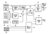
- FIG. 1 is a system configuration diagram of a drive control apparatus for a hybrid vehicle.
- FIG. 2 is a control block diagram of target engine operating point and target power calculation.
- FIG. 3 is a control block diagram for calculating the torque command value of the motor generator.
- FIG. 4 is a control flowchart for calculating the target engine operating point.
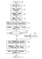
- FIG. 5 is a control flowchart for calculating the torque command value of the motor generator.
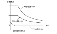
- FIG. 6 is a target driving force search map based on the vehicle speed and the accelerator opening.
- FIG. 7 is a target charge / discharge power search table according to the state of charge of the battery.
- FIG. 8 is a target engine operating point search map composed of engine torque and engine speed.
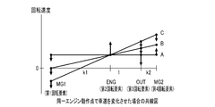
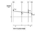
- FIG. 9 is a collinear diagram when the vehicle speed is changed at the same engine operating point.
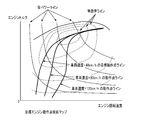
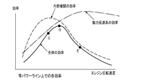
- FIG. 10 is a diagram showing the best line for engine efficiency and the best line for overall efficiency in a target engine operating point search map composed of engine torque and engine speed.
- FIG. 11 is a diagram showing each efficiency on the equal power line composed of the efficiency and the engine speed.
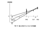
- FIG. 12 is a collinear diagram of each point (D, E, F) on the equal power line.
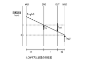
- FIG. 13 is a collinear diagram of the LOW gear ratio state.
- FIG. 14 is a collinear diagram of the intermediate gear ratio state.
- FIG. 15 is a collinear diagram of the HIGH gear ratio state.
- FIG. 16 is a collinear diagram in a state where power circulation occurs.
- FIG. 17 is a power upper / lower limit value search table according to battery temperature.
- FIG. 18 is a power upper / lower limit limit value search table based on battery voltage.
- FIG. 19 is a power upper / lower limit limit value search table according to the state of charge of the battery.
- reference numeral 1 denotes a hybrid vehicle drive control device.
- the drive control apparatus 1 for a hybrid vehicle includes, as a drive system, an output shaft 3 of an internal combustion engine 2 that generates a drive force by combustion of fuel, and a first motor that generates a drive force by electricity and generates electric energy by drive.
- a differential gear mechanism 8 that is a connected power transmission mechanism.
- the internal combustion engine 2 includes an air amount adjusting means 9 such as a throttle valve that adjusts the amount of air to be sucked in accordance with the accelerator opening (the amount of depression of the accelerator pedal), and fuel that supplies fuel corresponding to the amount of air to be sucked in.
- a fuel supply means 10 such as an injection valve and an ignition means 11 such as an ignition device for igniting the fuel are provided.
- the combustion state of the fuel is controlled by the air amount adjusting means 9, the fuel supply means 10 and the ignition means 11, and a driving force is generated by the combustion of the fuel.
- the first motor generator 4 includes a first motor rotor shaft 12, a first motor rotor 13, and a first motor stator 14.
- the second motor generator 5 includes a second motor rotor shaft 15, a second motor rotor 16, and a second motor stator 17.
- the first motor stator 14 of the first motor generator 4 is connected to the first inverter 18.
- the second motor stator 17 of the second motor generator 5 is connected to the second inverter 19.
- the power terminals of the first inverter 18 and the second inverter 19 are connected to the battery 20.
- the battery 20 is power storage means that can exchange power between the first motor generator 4 and the second motor generator 5.
- the first motor generator 4 and the second motor generator 5 control the amount of electricity supplied from the battery 20 by the first inverter 18 and the second inverter 19, respectively, and generate driving force by the supplied electricity. At the same time, electric energy is generated by the driving force from the driving wheel 6 during regeneration, and the battery 20 is charged with the generated electric energy.
- the differential gear mechanism 8 includes a first planetary gear mechanism 21 and a second planetary gear mechanism 22.
- the first planetary gear mechanism 21 includes a first sun gear 23, a first planetary carrier 25 that supports a first planetary gear 24 that meshes with the first sun gear 23, and a first ring gear 26 that meshes with the first planetary gear 24.
- the second planetary gear mechanism 22 includes a second sun gear 27, a second planetary carrier 29 that supports a second planetary gear 28 that meshes with the second sun gear 27, and a second ring gear 30 that meshes with the second planetary gear 28. It has.
- the differential gear mechanism 8 is configured such that the rotation center lines of the rotating elements of the first planetary gear mechanism 21 and the second planetary gear mechanism 22 are arranged on the same axis, and between the internal combustion engine 2 and the first planetary gear mechanism 21.
- the first motor generator 4 is disposed on the second planetary gear mechanism 22, and the second motor generator 5 is disposed on the second planetary gear mechanism 22 on the side away from the internal combustion engine 2.
- the second motor generator 5 has a performance capable of running the vehicle with only a single output.
- the first motor rotor shaft 12 of the first motor generator 4 is connected to the first sun gear 23 of the first planetary gear mechanism 21.
- the first planetary carrier 25 of the first planetary gear mechanism 21 and the second sun gear 27 of the second planetary gear mechanism 22 are coupled and connected to the output shaft 3 of the internal combustion engine 2 via the one-way clutch 31.
- the first ring gear 26 of the first planetary gear mechanism 21 and the second planetary carrier 29 of the second planetary gear mechanism 22 are coupled and coupled to the output unit 32.
- the output unit 32 is connected to the drive shaft 7 via an output transmission mechanism 33 such as a gear or a chain.
- the second motor rotor shaft 15 of the second motor generator 5 is connected to the second ring gear 30 of the second planetary gear mechanism 9.
- the one-way clutch 31 is a mechanism that fixes the output shaft 3 of the internal combustion engine 2 so as to rotate only in the output direction, and prevents the output shaft 3 of the internal combustion engine 2 from reversing.
- the driving power of the second motor generator 5 is transmitted as the driving power of the output unit 32 via the reaction force of the one-way clutch 31.
- the hybrid vehicle outputs the power generated by the internal combustion engine 2, the first motor generator 4, and the second motor generator 5 to the drive shaft 7 via the first planetary gear mechanism 21 and the second planetary gear mechanism 21. Then, the driving wheel 6 is driven.
- the hybrid vehicle transmits the driving force from the driving wheels 6 to the first motor generator 4 and the second motor generator 5 via the first planetary gear mechanism 21 and the second planetary gear mechanism 22, Electric energy is generated to charge the battery 20.
- the differential gear mechanism 8 has four rotating elements 34-37.
- the first rotating element 34 includes the first sun gear 23 of the first planetary gear mechanism 21.
- the second rotating element 35 is formed by combining the first planetary carrier 25 of the first planetary gear mechanism 21 and the second sun gear 27 of the second planetary gear mechanism 22.
- the third rotating element 36 is formed by coupling the first ring gear 26 of the first planetary gear mechanism 21 and the second planetary carrier 29 of the second planetary gear mechanism 22.
- the fourth rotating element 37 includes the second ring gear 30 of the second planetary gear mechanism 22.
- the differential gear mechanism 8 includes four rotating elements 34 to 37 on a collinear chart in which the rotational speeds of the four rotating elements 34 to 37 can be represented by straight lines.
- MG1 indicates the first motor generator 4
- MG2 indicates the second motor generator 5
- ENG indicates the internal combustion engine 2
- OUT indicates the output unit 32.
- the first motor rotor shaft 12 of the first motor generator 4 is connected to the first rotating element 34.
- the output shaft 3 of the internal combustion engine 2 is connected to the second rotation element 35 via a one-way clutch 31.
- An output unit 32 is connected to the third rotation element 36.
- the output shaft 32 is connected to the drive shaft 7 via an output transmission mechanism 33.
- a second motor rotor shaft 15 of the second motor generator 5 is connected to the fourth rotating element 37.
- the differential gear mechanism 8 has four rotating elements 34 to 37 connected to the output shaft 3, the first motor generator 4, the second motor generator 5, and the drive shaft 7, respectively. Power is exchanged among the output shaft 3, the first motor generator 4, the second motor generator 5, and the drive shaft 7. Therefore, the drive control device 1 is a “4-axis” control method.
- an air amount adjusting unit 9, a fuel supply unit 10, an ignition unit 11, a first inverter 18, and a second inverter 19 are connected to a drive control unit 38.
- the drive control unit 38 is connected with an accelerator opening degree detection means 39, a vehicle speed detection means 40, an engine rotation speed detection means 41, and a battery charge state detection means 42.
- the accelerator opening detection means 39 detects the accelerator opening that is the amount of depression of the accelerator pedal.
- the vehicle speed detection means 40 detects the vehicle speed (vehicle speed) of the hybrid vehicle.
- the engine speed detection means 41 detects the engine speed of the internal combustion engine 2.
- the battery charge state detection means 42 detects the charge state SOC of the battery 20.
- the drive control unit 38 includes a target driving force setting unit 43, a target driving power setting unit 44, a target charge / discharge power setting unit 45, a target engine power calculation unit 46, a target engine operating point setting unit 47, Motor torque command value calculation means 48 is provided.
- the target driving force setting means 43 drives the hybrid vehicle based on the accelerator opening detected by the accelerator opening detecting means 39 and the vehicle speed detected by the vehicle speed detecting means 40, as shown in FIG.
- the target driving force for this purpose is determined by searching the target driving force search map shown in FIG.
- the target drive power setting means 44 sets the target drive power based on the accelerator opening detected by the accelerator opening detection means 39 and the vehicle speed detected by the vehicle speed detection means 40.
- the target driving power is set based on the vehicle speed detected by the vehicle speed detecting means 40 and the target driving force set by the target driving force setting means 43.
- the target charge / discharge power setting means 45 sets the target charge / discharge power based on at least the state of charge SOC of the battery 20 detected by the battery charge state detection means 42.
- the target charge / discharge power is searched and set by the target charge / discharge power search table shown in FIG. 7 according to the state of charge SOC of the battery 20 and the vehicle speed.
- the target charge / discharge power is set such that the absolute value decreases as the vehicle speed decreases.
- the target engine power calculation means 46 calculates the target engine power from the target drive power set by the target drive power setting means 44 and the target charge / discharge power set by the target charge / discharge power setting means 45.
- the target engine operating point setting means 47 sets a target engine operating point (target engine rotational speed and target engine torque) from the target engine power and the overall system efficiency of the drive control device 1.
- the vehicle speed is searched for and set by the target engine operating point search map shown in FIG.
- the motor torque command value calculation means 48 calculates the respective target rotation speeds of the first motor generator 4 and the second motor generator 5 and sets the torque command values.
- the drive control unit 38 includes a power loss estimation unit 49, a target power setting unit 50, and a power upper / lower limit value calculation unit 51.
- the drive control unit 38 is connected to a temperature detection unit 52 that detects the temperature of the battery 20 and a voltage detection unit 53 that detects the voltage of the battery 20.
- the power loss estimation means 49 is configured to output the previous value (Nmg1t (n-1)) of the target rotational speed of the first motor generator 4 and the previous value (Tmg1t (n-1) of the torque command value.
- the estimated power that is the power loss of the motor generator 4 and the second motor generator 5 is calculated.
- the power loss estimation unit 49 searches for an estimated power as a power loss from a power loss search map.
- the estimated power as power loss increases as the target driving force increases, and the increase rate increases as the target driving force increases. Further, the estimated power as the power loss increases as the vehicle speed increases, and the target driving force that takes the maximum value decreases as the vehicle speed increases.
- the power loss estimation means 49 calculates the power loss of the first motor generator 4 by a quadratic polynomial having the target rotational speed (previous value) and the torque command value (previous value) of the first motor generator 4 as variables. And an estimated power loss of the second motor generator 5 by a quadratic polynomial having the target rotational speed (previous value) and the torque command value (previous value) of the second motor generator 5 as variables. Calculate power.
- the target engine power calculation means 46 calculates the target engine power based on the target drive power, the target charge / discharge power, and the estimated power that is the power loss.
- the target power setting means 50 is a target value of input / output power from the battery 20 from the difference between the target engine power calculated by the target engine power calculation means 46 and the target drive power set by the target drive power setting means 44. Set the target power.
- the motor torque command value calculation means 48 uses the torque balance expression including the target engine torque obtained from the target engine operating point and the power balance expression including the target power set by the target power setting means 50, and The torque command values of the first motor generator 4 and the second motor generator 5 are calculated. In this power balance equation, the power generated or consumed by the first motor generator 4 and the second motor generator 5 and the estimated power that becomes the power loss in the first motor generator 4 and the second motor generator 5 The input / output power of the battery 20 is included.
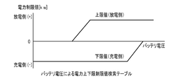
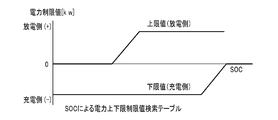
- the power upper / lower limit calculating means 51 sets an upper power limit value and a lower power limit value for limiting input / output power to / from the battery based on the state parameter of the battery 20. As shown in FIG. 2, the power upper and lower limit value calculation means 51 determines the temperature detected by the temperature detection means 52, the voltage detected by the voltage detection means 53, and the charge state detected by the battery charge state detection means 42. The estimated power is subtracted from a search value obtained from a search table (FIGS. 17 to 19) based on temperature, voltage, and state of charge as a state parameter of the battery 20, and the power upper limit value or the power Determine the lower limit.
- a search table FIG. 17 to 19
- the target power calculation means 51 calculates a target power from the difference between the target engine power calculated from the target engine power calculation means 46 and the target drive power, and the target power is calculated based on the power upper limit value and the power lower limit value. When deviating from the range set by, the power upper limit value or the power lower limit value is limited.
- the torque command value of the first motor generator 4 and the torque command value of the second motor generator 5 by the motor torque command value calculation means 48 are obtained by the first to seventh calculators 54 to 60, respectively.
- MG 1 indicates the first motor generator 4
- MG 2 indicates the second motor generator 5.
- the first calculation unit 54 The target rotational speed Nmg1t (n) of the first motor generator 4 and the target rotational speed Nmg2t (n) of the second motor generator 5 are calculated.
- the second calculator 55 sets the target rotational speed Nmg1t (n) of the first motor generator 4 and the target rotational speed Nmg2t (n) of the second motor generator 5 and the target power setting calculated by the first calculator 54. Based on the target power set by the means 50 and the target engine torque set by the target engine operating point setting means 47, the basic torque Tmg1i of the first motor generator 4 is calculated. The third calculator 56 calculates the second motor generator based on the basic torque Tmg1i of the first motor generator 4 calculated by the second calculator 55 and the target engine torque set by the target engine operating point setting means 47. 5 basic torque Tmg2i is calculated.
- the fourth calculator 57 calculates the feedback correction torque of the first motor generator 4 based on the engine speed detected by the engine speed detector 41 and the target engine speed set by the target engine operating point setting means 47. Tmg1fb is calculated.
- the fifth calculator 58 determines the feedback correction torque of the second motor generator 5 based on the engine speed detected by the engine speed detector 41 and the target engine speed set by the target engine operating point setting means 47. Tmg2fb is calculated.
- the sixth calculator 59 is based on the basic torque Tmg1i of the first motor generator 4 calculated by the second calculator 55 and the feedback correction torque Tmg1fb of the first motor generator 4 calculated by the fourth calculator 57.
- the torque command value Tmg1 (n) of the first motor generator 4 is calculated.
- the seventh calculator 60 is based on the basic torque Tmg2i of the second motor generator 5 calculated by the third calculator 56 and the feedback correction torque Tmg2fb of the second motor generator 5 calculated by the fifth calculator 58.
- the torque command value Tmg2 (n) of the second motor generator 5 is calculated.
- the drive control unit 38 operates the internal combustion engine 2 at the target engine operating point (target engine rotational speed and target engine torque) set by the target engine operating point setting means 47.
- the driving state of the air amount adjusting means 9, the fuel supply means 10 and the ignition means 11 is controlled.
- the drive control unit 38 first sets the torque command value set by the motor torque command value calculation unit 48 so that the state of charge (SOC) of the battery 20 becomes the target power set by the target power setting unit 50.
- SOC state of charge
- the driving states of the motor generator 4 and the second motor generator 5 are controlled.
- the hybrid vehicle drive control device 1 determines the target engine operating point (target engine speed) from the driver's accelerator operation amount (accelerator opening) and vehicle speed. (Speed, target engine torque) is calculated, and each of the first motor generator 4 and the second motor generator 5 is calculated based on the target engine operating point, as shown in the control flowchart for calculating the motor torque command value in FIG. Calculate the torque command value.
- step 101 the accelerator opening detected by the accelerator opening detecting means 39 and the vehicle speed detecting means 40 are detected.
- Vehicle speed, engine rotation speed detected by the engine rotation speed detection means 41, battery state of charge SOC detected by the battery charge state detection means 42, temperature detected by the temperature detection means 52, voltage detected by the voltage detection means 53 Capture various signals.
- step 102 the target driving force according to the vehicle speed and the accelerator opening is calculated from the target driving force detection map (see FIG. 6).
- the target driving power calculated in step 102 and the vehicle speed are multiplied to calculate a target driving power necessary for driving the hybrid vehicle with the target driving force.
- a target charge / discharge amount is calculated from a target charge / discharge power search table shown in FIG. When the state of charge SOC of the battery 20 is low, the target charge / discharge power is increased to the charge side so as to prevent overdischarge of the battery 20.
- the target charge / discharge power is increased to the discharge side so as to prevent overcharge.
- the target charge / discharge power is treated as a positive value on the discharge side and a negative value on the charge side for convenience.
- the previous calculated value Nmg1t (n-1) of the target rotational speed of the first motor generator 4 and the previous calculated value Tmg1 (n-1) of the target torque, and the target rotational speed of the second motor generator 5 are set.
- the first motor generator 4 and the second motor generator 5 are approximated by a quadratic polynomial having the previous calculated value Nmg2t (n-1) and the previous calculated value Tmg2 (n-1) of the target torque as variables.
- the power loss is calculated, and the total is used as the power loss for the subsequent calculations. At this time, since the operating points of the first motor generator 4 and the second motor generator 5 are not yet determined, the values calculated the last time are used.
- Ploss 2 a 2 (Tmg2) 2 (Nmg2) 2 + b 2 (Tmg2) 2 (Nmg2) + C 2 (Tmg2) 2 + d 2 (Tmg2) (Nmg2) 2 + E 2 (Tmg2) (Nmg2) + f 2 (Tmg2) + G 2 (Nmg2) 2 + h 2 (Nmg2) + i 2
- step 106 the power (target engine power) to be output by the internal combustion engine 2 is calculated from the target drive power, the target charge / discharge power, and the power loss.
- the power to be output from the internal combustion engine 2 is a value obtained by adding (subtracting in the case of discharging) the power required to charge the battery 20 to the power required for driving the hybrid vehicle.
- the target engine power is calculated by subtracting the target charge / discharge power from the target drive power and adding the power loss.
- step 107 it is determined whether the calculated target engine power exceeds an upper limit value. If this determination (107) is YES, the upper limit value is replaced with the target engine power (108), and the routine proceeds to step 109. If this determination (107) is NO, the routine proceeds to step 109.
- step 107 and step 108 the upper limit value of the target engine power is limited.
- the upper limit value is the maximum output value that the internal combustion engine 2 can output.
- the power upper limit value and the power lower limit value are calculated from the power upper and lower limit limit value search tables of the temperature, voltage, and state of charge of the battery 20 shown in FIGS.
- the discharge side is treated as a positive value and the charge side is treated as a negative value.
- the minimum value on the discharge side is used as the power upper limit value, and the value on which the absolute value on the charge side is minimized Calculated as the lower power limit.
- FIG. 17 shows an example of restriction due to the temperature of the battery 20. When the temperature is low, the reaction speed of the battery 20 is reduced, so that the chargeable / dischargeable power is reduced.
- FIG. 18 shows an example of restriction by the voltage of the battery 20.
- the battery 20 has an upper limit voltage and a lower limit voltage for protection. If the battery 20 is used beyond the range, the battery 20 will deteriorate. Therefore, it is necessary to limit charging when the voltage is high, and limit discharging when the voltage is low.
- FIG. 19 shows an example of restriction by the state of charge SOC of the battery 20. The state of charge SOC of the battery 20 needs to be prevented from being overdischarged or overcharged. When the state of charge SOC is low, discharging must be limited, and when the state of charge SOC is high, charging must be limited. .
- the charge power is reduced when the state of charge SOC is high so as not to overcharge, but this value is the generated power using the power of the internal combustion engine 2.
- this value is the generated power using the power of the internal combustion engine 2.
- the limit value on the charging side shown in FIG. When the driver's required power requires power assist by the battery 20, power assist is executed as will be described later. In this case, the state of charge SOC decreases according to power consumption. If the power assist is frequently performed, the power assist is executed again before the state of charge SOC recovers, so that the state of charge SOC gradually decreases. In such a case, the discharge side is limited.
- step 110 the target engine power is subtracted from the target drive power and limited by the power upper and lower limit values to calculate the target power.
- the target power is a value that means the assist power by the power of the battery 20.
- the target power is a value that means the charging power to the battery 20.
- a target engine operating point corresponding to the target engine power and vehicle speed is calculated from the target engine operating point search map shown in FIG. 8, and the process returns (112).
- the target engine operating point search map (FIG. 8) is a power transmission constituted by the differential gear mechanism 8, the first motor generator 4 and the second motor generator 5 for the efficiency of the internal combustion engine 2 on the equal power line.
- the line that selects and connects the points at which the overall efficiency, which takes the system efficiency into consideration, for each power is connected is set as the target engine operating point line.
- Each target engine operating point line is set for each vehicle speed (in FIG. 8, 40 km / h, 80 km / h, 120 km / h).
- the set value of the target engine operating point line may be obtained experimentally or calculated from the efficiency of the internal combustion engine 2, the first motor generator 4, and the second motor generator 5. Note that the target engine operating point line is set to move to the high rotation side as the vehicle speed increases.
- the first motor generator 4 operates as an electric motor
- the second motor generator 5 operates as a generator. Decreases the efficiency. Therefore, as indicated by a point C in FIG. 11, the efficiency of the power transmission system is lowered even if the efficiency of the internal combustion engine 2 is good, and the overall efficiency is lowered. Therefore, in order to prevent the power circulation from occurring in the high vehicle speed range, the rotational speed of the first motor generator 4 may be set to 0 or more as shown in E of the alignment chart shown in FIG.
- the engine operating point moves toward the higher engine rotation speed of the internal combustion engine 2, so that the efficiency of the internal combustion engine 2 is improved even if the efficiency of the power transmission system is improved, as indicated by the point E in FIG. As a result, the overall efficiency is lowered. Therefore, as shown in FIG. 11, the point with high overall efficiency is D between the two, and if this point is set as the target engine operating point, the most efficient operation is possible. As described above, FIG. 10 shows the three engine operating points C, D, and E on the target engine operating point search map. When the vehicle speed is high, the operating point with the best overall efficiency is the engine efficiency. It turns out that it moves to the high rotation side from the best operating point.
- the target rotational speed Nmg1t of the first motor generator 4 and the target rotational speed Nmg2t of the second motor generator 5 are expressed by the following equation (1), Calculate by (2).
- the arithmetic expressions (1) and (2) are obtained from the relationship between the rotational speeds of the first planetary gear mechanism 21 and the second planetary gear mechanism 22.
- Nmg1t (n) (Net-No) * k1 + Net (1)
- Nmg2t (n) (No-Net) * k2 + No (2)
- k1 and k2 are values determined by the gear ratio of the first planetary gear mechanism 21 and the second planetary gear mechanism 22 as described later.
- step 202 the target rotational speed Nmg1t (n) of the first motor generator 4 and the target rotational speed Nmg2t (n) of the second motor generator 5 obtained in step 201, the target charge / discharge power Patt, the target From the engine torque Tet, the basic torque Tmg1i of the first motor generator 4 is calculated by the following calculation formula (3).
- Tmg1i ( ⁇ (B 1 + A 2 (2Tet (1 + k1) / k2 2 ) + B 2 (1 + k1) / K2 + Nmg1 * 2 ⁇ / 60 + Nmg2 * 2 ⁇ / 60 * (1 + k1) / K2) + ((B 1 + A 2 * 2Tet (1 + k1) / k2 2 + B 2 (1 + k1) / K2 + Nmg1 * 2 ⁇ / 60 + Nmg2 * 2 ⁇ / 60 * (1 + k1) / K2) 2 -4 (A 1 + A 2 (1 + k1) 2 / k2 2 ) (C 1 + C 2 + A 2 Tet 2 / K2 2 + B 2 Tet / k2 + Nmg2 * 2 ⁇ / 60 * Tet / k2 -Pbatt)) 1/2 ) / 2 (A 1 + A 2 (1 + k1) 2 / k2 2 ) (3)
- a 1 a 1 Nmg1 2 + b 1 Nmg1 + c 1
- B 1 d 1 Nmg 1 2 + e 1 Nmg 1 + f 1
- C 1 g 1 Nmg1 2 + h 1 Nmg1 + i 1
- a 2 a 2 Nmg1 2 + b 2 Nmg1 + c 2
- B 2 d 2 Nmg1 2 + e 2 Nmg1 + f 2
- C 2 g 2 Nmg1 2 + h 2 Nmg1 + i 2 (a 1 , b 1 ... i 1 , a 2 , b 2 ... i 2 are constants used in the approximate expression for power loss.)
- This arithmetic expression (3) includes the following torque balance expression (4) representing the balance of torque input to the first planetary gear mechanism 21 and the second planetary gear mechanism 22, and the first motor generator 4 and the first It can be derived by solving a simultaneous equation from the power balance equation (5) indicating that the power (including loss) generated or consumed by the two motor generators 5 and the input / output power (Pbatt) to the battery 20 are equal.
- step 203 the basic torque Tmg2i of the second motor generator 5 is calculated from the basic torque Tmg1i of the first motor generator 4 and the target engine torque by the following equation (6).
- Tmg2i (Te + (1 + k1) * Tmg1i) / k2 (6)
- This equation is derived from the above equation (4).
- step 204 in order to bring the engine rotation speed closer to the target, the deviation of the engine rotation speed Ne from the target engine rotation speed Net is multiplied by a predetermined feedback gain, and the feedback of the first motor generator 4 is performed.
- Correction torque Tmg1fb and feedback correction torque Tmg2fb of second motor generator 5 are calculated.
- step 205 the feedback correction torque Tmg1fb of the first motor generator 4 is added to the basic torque Tmg1i to calculate a torque command value Tmg1 (n) that is a control command value, and the feedback correction torque Tmg2fb of the second motor generator 5 is calculated.
- a torque command value Tmg2 (n) which is a control command value, is calculated by adding to the basic torque Tmg2i, and the process returns (206).
- the drive control unit 38 outputs the target driving force by controlling the first motor generator 4 and the second motor generator 5 according to the torque command values Tmg1 (n) and Tmg2 (n). Charge / discharge to the battery 20 can be set as a target value.
- the rotational speed is the direction in which the rotation direction of the output shaft 3 of the internal combustion engine 2 is the positive direction
- the torque input / output to / from each shaft is the direction in which the torque in the same direction as that of the output shaft 3 of the internal combustion engine 2 is input
- a torque for driving the hybrid vehicle forward is output (driving when the vehicle is moving forward, decelerating when the vehicle is moving backward).
- the first inverter 18 and the second inverter 19 and the first motor generator 4 and the second motor generator 5 cause loss due to heat generation, so the efficiency when converting between electrical energy and mechanical energy is not 100%.
- the description will be made assuming that there is no loss.
- control is performed so that extra power is generated by the amount of energy lost due to the loss.
- the hybrid vehicle drive control device 1 includes the target drive power setting unit 44 that sets the target drive power based on the accelerator opening and the vehicle speed, and the target charge / discharge based on at least the state of charge of the battery 20.
- Target engine operating point based on target engine power and overall system efficiency
- target charge / discharge power setting means 45 for setting power
- target engine power calculating means 46 for calculating target engine power from target drive power and target charge / discharge power
- Target engine operating point setting means 47 for setting the motor
- motor torque command value calculating means 48 for calculating the target rotational speeds of the first motor generator 4 and the second motor generator 5 and for setting the respective torque command values.
- the torque correction value (feedback correction torque) of the first motor generator 4 and the torque correction value (feedback correction torque) of the second motor generator 5 are calculated.
- the calculation is based on the deviation between the actual engine speed and the target engine speed, and the ratio between the torque correction value of the first motor generator 4 and the torque correction value of the second motor generator 5 is the power input / output.
- a predetermined ratio based on the lever ratio of the differential gear mechanism 8 of the apparatus is set. Thereby, the drive control apparatus 1 of the hybrid vehicle cancels out the torque fluctuation of the internal combustion engine 2 using the torque balance formula focusing on the torque change with the drive shaft 7 as a fulcrum.
- the differential gear mechanism 8 as a power input / output device has four rotating elements 34 to 37 connected to the first rotating element 34 and the internal combustion engine 2 sequentially connected to the first motor generator 4 in the alignment chart.
- the second rotation element 35, the third rotation element 36 connected to the drive shaft 7, and the fourth rotation element 37 connected to the second motor generator 5 are arranged in this order, and the mutual lever ratio between these rotation elements In the same order as k1: 1: k2, and the torque correction value of the first motor generator 4 and the torque correction value of the second motor generator 5 are multiplied by the torque correction value of the first motor generator 4 by k1.
- the value is set so as to maintain a relationship in which the value obtained by multiplying the torque correction value of the second motor generator 5 by 1 + k2 is equal.
- the torque balance type can be preferably used when the differential gear mechanism 8 having the same four rotating elements and having different lever ratios is configured.
- the drive control device 1 sets the feedback correction amounts set for the torque command values of the first motor generator 4 and the second motor generator 5 to the first motor generator 4 and the second motor generator 5 and the drive shaft. 7 and the internal combustion engine 2 are set in association with each other based on the gear ratio or lever ratio of the differential gear mechanism 8 having four rotating elements 34 to 37 connected to the internal combustion engine 2 respectively.
- the target torque (torque command value) of each of the first motor generator 4 and the second motor generator 5 and the target engine torque of the internal combustion engine 2 are: Based on the lever ratio based on the gear ratio of the differential gear mechanism 8 which is a power input / output device that mechanically connects the first motor generator 4 and the second motor generator 5 and the internal combustion engine 2 in balance. Yes.
- the motor torque command value calculating means 48 uses the first motor generator 4 and the second motor generator 5 by using a torque balance formula including the target engine torque obtained from the target engine operating point and a power balance formula including the target power. Torque command values of the first motor generator 4 and the second motor generator 5 so that the actual engine rotation speed is converged to the target engine rotation speed obtained from the target engine operating point. It is possible to perform each feedback correction.
- the hybrid which calculates the target rotational speed and the torque command value of each of the first motor generator 4 and the second motor generator 5 using the torque balance formula including the target engine torque and the power balance formula including the target power.
- the vehicle drive control device 1 can control the first motor generator 4 and the second motor generator 5 when the battery 20 is charged and discharged. Considering the engine operating point of the internal combustion engine 2, it is possible to achieve both a target driving force and a target charge / discharge. By finely correcting the torque command values of the first motor generator 4 and the second motor generator 5, respectively, the engine speed can be quickly converged to the target value. Since the engine operating point can be combined with the target operating point, an appropriate operating state can be achieved.
- the hybrid vehicle drive control device 1 is a first motor generator in the case where there is charge / discharge of the battery 20 in a hybrid system including the internal combustion engine 2, the first motor generator 4, and the second motor generator 5.
- the control of the internal combustion engine 2 is performed when performing the control to ensure the target driving force and the target charge / discharge. It is possible to improve the drivability and running feeling by optimizing the torque fluctuation so as not to affect the driving torque.
- the hybrid vehicle drive control device 1 calculates power loss estimation means 49 that calculates estimated power that is a power loss based on the target rotational speed and torque command value of the first motor generator 4 and the second motor generator 5. And target power calculation means 50 for calculating the target power from the difference between the target engine power and the target drive power.
- the target engine power calculation means 46 has the target drive power, the target charge / discharge power, and this power loss.
- the target engine power is calculated based on the estimated power, and the motor torque command value calculation means 48 uses the torque balance formula including the target engine torque obtained from the target engine operating point and the power balance formula including the target power.
- the power balance equation includes the estimated power that is the power generated or consumed by the first motor generator 4 and the second motor generator 5 and the power loss in the first motor generator 4 and the second motor generator 5.
- the input / output power of the battery 20 is included.
- the drive control device 1 considers the power loss of the first motor generator 4 and the second motor generator 5 and limits the input / output power according to the state of the battery 20 to thereby reduce the power of the battery 20. Since the charge / discharge power when performing power assist using can be appropriately limited, overdischarge and overload to the battery 20 can be prevented.
- the drive control device 1 can improve the control accuracy of the state of charge SOC of the battery 20 in consideration of the power loss of the first motor generator 4 and the second motor generator 5, and the control accuracy is high. Therefore, the range near the limit value of the battery 20 can be used, and the regeneration amount can be increased during deceleration. Since the drive control apparatus 1 performs calculation including the power loss in the power balance equation, it is possible to improve the control accuracy of the drive force distribution to the first motor generator 4 and the second motor generator 5. In addition, the drive control device 1 takes into consideration the operating point of the internal combustion engine 1 and prevents the first motor generator 4 and the second motor generator 5 from securing a target driving force and preventing overcharging / discharging of the battery 20.
- the drive control device 1 sets the target power different from the target charge / discharge power based on the target engine speed after resetting the target engine speed so that it does not exceed the target engine speed upper limit value. Therefore, the driving power of the first motor generator 4 and the second motor generator 5 is set based on the optimized target engine operating point and the optimal target power that prevents overcharge / discharge.
- the engine rotational speed is limited to protect the internal combustion engine 2, and the driving force requested by the driver can be satisfied by the power assist using the electric power of the battery 20.
- the power loss estimation means 49 calculates the power loss of the first motor generator 4 by a quadratic polynomial having the target rotational speed (previous value) and the torque command value (previous value) of the first motor generator 4 as variables. And an estimated power loss of the second motor generator 5 by a quadratic polynomial having the target rotational speed (previous value) and the torque command value (previous value) of the second motor generator 5 as variables. Calculate power.
- the drive control device 1 calculates the power loss included in the power balance equation with higher accuracy, thereby improving the calculation accuracy of the charge / discharge power, preventing overdischarge and overload on the battery 20, The control accuracy of the driving force distribution to the motor generator 4 and the second motor generator 5 can be improved.
- the drive control device 1 is provided with power upper and lower limit value calculating means 51 for setting an upper power limit value and a power lower limit value for restricting input / output power to / from the battery 20 based on a state parameter of the battery 20, and the target power calculating means 50 calculates the target power from the difference between the target engine power and the target drive power, and when the target power is out of the range set by the power upper limit value and the power lower limit value, the power upper limit value or the power lower limit value. Limit to. Thereby, the drive control device 1 calculates the target engine operating point and the target power based on the target engine power calculated in consideration of the power loss, and the first motor generator 4 and the second motor generator 5 respectively.
- the power upper / lower limit calculating means 51 subtracts the estimated power from the search value obtained from the search table based on the temperature, voltage, and state of charge as the state parameter of the battery 20, and determines the power upper limit value or the power lower limit value.
- the power upper / lower limit calculating means 51 includes a power upper / lower limit value search table (FIG. 17) that defines the power upper limit value and the power lower limit value with respect to the temperature of the battery 20, and the power upper limit value and the power lower limit value with respect to the voltage of the battery 20.
- a power upper / lower limit value search table (FIG. 19) that defines an upper power limit value and a power lower limit value for the state of charge SOC of the battery 20.
- the power upper and lower limit value calculation means 51 inputs the temperature, voltage, and state of charge SOC of the battery 20 as the state parameters of the battery 20, and inputs the power upper limit value and power lower limit value defined based on the input temperature, The power upper limit value and the power lower limit value defined based on the input voltage and the power upper limit value and the power lower limit value defined based on the input state of charge SOC are obtained, and the estimated power is subtracted to obtain the respective power upper limit values. Then, the power lower limit values are compared with each other, and the power upper limit value and the power lower limit value having the largest restrictions are output to the target power calculation means 50.
- the drive control device 1 performs overvoltage protection of the battery 20 in charge / discharge and overdischarge prevention / overcharge prevention in consideration of the charge state SOC. It can be carried out.
- This invention can improve the control accuracy of the state of charge of the battery in consideration of the power loss of a plurality of motor generators, and can be applied to the driving force control of a hybrid vehicle.
Landscapes
- Engineering & Computer Science (AREA)
- Transportation (AREA)
- Mechanical Engineering (AREA)
- Chemical & Material Sciences (AREA)
- Combustion & Propulsion (AREA)
- Power Engineering (AREA)
- Life Sciences & Earth Sciences (AREA)
- Sustainable Development (AREA)
- Sustainable Energy (AREA)
- Automation & Control Theory (AREA)
- Electric Propulsion And Braking For Vehicles (AREA)
- Hybrid Electric Vehicles (AREA)
Abstract
Priority Applications (5)
| Application Number | Priority Date | Filing Date | Title |
|---|---|---|---|
| JP2013500729A JPWO2012114430A1 (ja) | 2011-02-21 | 2011-02-21 | ハイブリッド車両の駆動制御装置 |
| US13/985,692 US9026293B2 (en) | 2011-02-21 | 2011-02-21 | Drive control device of hybrid vehicle |
| DE112011104926T DE112011104926T5 (de) | 2011-02-21 | 2011-02-21 | Antriebssteuergerät eines hybriden Fahrzeugs |
| CN201180068213.2A CN103402840B (zh) | 2011-02-21 | 2011-02-21 | 混合动力车辆的驱动控制装置 |
| PCT/JP2011/053690 WO2012114430A1 (fr) | 2011-02-21 | 2011-02-21 | Dispositif de commande de conduite de véhicule hybride |
Applications Claiming Priority (1)
| Application Number | Priority Date | Filing Date | Title |
|---|---|---|---|
| PCT/JP2011/053690 WO2012114430A1 (fr) | 2011-02-21 | 2011-02-21 | Dispositif de commande de conduite de véhicule hybride |
Publications (1)
| Publication Number | Publication Date |
|---|---|
| WO2012114430A1 true WO2012114430A1 (fr) | 2012-08-30 |
Family
ID=46720251
Family Applications (1)
| Application Number | Title | Priority Date | Filing Date |
|---|---|---|---|
| PCT/JP2011/053690 Ceased WO2012114430A1 (fr) | 2011-02-21 | 2011-02-21 | Dispositif de commande de conduite de véhicule hybride |
Country Status (5)
| Country | Link |
|---|---|
| US (1) | US9026293B2 (fr) |
| JP (1) | JPWO2012114430A1 (fr) |
| CN (1) | CN103402840B (fr) |
| DE (1) | DE112011104926T5 (fr) |
| WO (1) | WO2012114430A1 (fr) |
Cited By (4)
| Publication number | Priority date | Publication date | Assignee | Title |
|---|---|---|---|---|
| WO2014149710A1 (fr) * | 2013-03-15 | 2014-09-25 | Allison Transmission, Inc. | Système et procédé d'équilibrage de débit d'énergie dans des transmissions automatiques hybrides |
| US8901888B1 (en) | 2013-07-16 | 2014-12-02 | Christopher V. Beckman | Batteries for optimizing output and charge balance with adjustable, exportable and addressable characteristics |
| EP3890152A1 (fr) | 2020-04-02 | 2021-10-06 | Yamaha Hatsudoki Kabushiki Kaisha | Dispositif de commande pour batterie de navire, son procédé de commande associé et navire |
| CN114030459A (zh) * | 2021-11-29 | 2022-02-11 | 深圳技术大学 | 混合动力车低温下防电池过充的控制方法、终端及介质 |
Families Citing this family (32)
| Publication number | Priority date | Publication date | Assignee | Title |
|---|---|---|---|---|
| CN103338999B (zh) * | 2011-01-31 | 2016-03-02 | 铃木株式会社 | 用于混合动力车辆的驱动控制装置和驱动控制方法及混合动力车辆 |
| CN103380043B (zh) * | 2011-02-21 | 2015-12-16 | 铃木株式会社 | 混合动力车辆的驱动控制装置 |
| JP5570655B2 (ja) * | 2011-04-08 | 2014-08-13 | 三菱電機株式会社 | 車両用電源システム |
| CN102849065A (zh) * | 2012-08-30 | 2013-01-02 | 重庆长安汽车股份有限公司 | Cvt混合动力电动汽车功率优化分配控制的方法及系统 |
| CN105102287B (zh) * | 2013-03-14 | 2019-04-12 | 艾里逊变速箱公司 | 用于混合动力电动车再生模式期间能量管理的系统和方法 |
| KR101343453B1 (ko) * | 2013-08-30 | 2013-12-19 | 국방과학연구소 | 엔진-발전기 제어방법 및 이를 이용한 직렬형 하이브리드 전투기동장비 |
| US9598071B2 (en) * | 2014-03-21 | 2017-03-21 | Ford Global Technologies, Llc | Method and system for adaptive motor power loss estimation in hybrid electric vehicles |
| JP6149772B2 (ja) * | 2014-03-24 | 2017-06-21 | トヨタ自動車株式会社 | ハイブリッド車両 |
| US9539997B2 (en) * | 2014-07-29 | 2017-01-10 | Cummins Inc. | Method of power split for hybrid powertrain |
| JP2016222100A (ja) * | 2015-05-29 | 2016-12-28 | スズキ株式会社 | 駆動制御システム |
| JP6245234B2 (ja) * | 2015-08-07 | 2017-12-13 | トヨタ自動車株式会社 | 車両の駆動装置 |
| US10137799B2 (en) * | 2015-12-18 | 2018-11-27 | Ford Global Technologies, Llc | System and method for controlling multiple electric drives |
| US10000200B2 (en) * | 2015-12-28 | 2018-06-19 | Robert Bosch Gmbh | Torque reserve in a hybrid system |
| US9637109B1 (en) | 2016-01-27 | 2017-05-02 | Ford Global Technologies, Llc | Hybrid electric vehicle |
| JP2017140867A (ja) | 2016-02-08 | 2017-08-17 | 株式会社デンソー | ハイブリッド車制御装置 |
| JP6468223B2 (ja) * | 2016-03-08 | 2019-02-13 | トヨタ自動車株式会社 | ハイブリッド自動車 |
| JP6458770B2 (ja) * | 2016-05-18 | 2019-01-30 | トヨタ自動車株式会社 | ハイブリッド自動車 |
| JP6458769B2 (ja) * | 2016-05-18 | 2019-01-30 | トヨタ自動車株式会社 | ハイブリッド自動車 |
| EP3511215B1 (fr) * | 2016-09-12 | 2023-10-11 | Kabushiki Kaisha Toshiba | Véhicule |
| US10322711B2 (en) * | 2016-10-04 | 2019-06-18 | Ford Global Technologies, Llc | Low-voltage battery charging split of hybrid vehicles with belt integrated starter-generators |
| US11167745B2 (en) * | 2018-04-19 | 2021-11-09 | Toyota Jidosha Kabushiki Kaisha | Control system of hybrid vehicle |
| JP7207237B2 (ja) * | 2019-08-29 | 2023-01-18 | トヨタ自動車株式会社 | ハイブリッド車両 |
| JP7238699B2 (ja) | 2019-08-29 | 2023-03-14 | トヨタ自動車株式会社 | ハイブリッド車両 |
| DE102019132941B4 (de) * | 2019-12-04 | 2021-09-30 | Schaeffler Technologies AG & Co. KG | Antriebseinheit und Antriebsanordnung |
| US20230039195A1 (en) * | 2020-01-14 | 2023-02-09 | Nidec Corporation | Motor unit and electric car |
| CN113734141B (zh) * | 2020-05-27 | 2024-05-28 | 广州汽车集团股份有限公司 | 一种车辆怠速发电功率控制方法及其系统 |
| US11407400B2 (en) * | 2020-06-02 | 2022-08-09 | Toyota Motor Engineering & Manufacturing North America, Inc. | Control of automatic transmission during charging of a battery in a hybrid-electric vehicle |
| CN113131018A (zh) * | 2021-03-31 | 2021-07-16 | 东莞新能安科技有限公司 | 一种电池包功率均衡方法及系统、电池系统与电池包 |
| CN113370965B (zh) * | 2021-06-21 | 2022-09-20 | 同济大学 | 一种混合动力汽车的工作点选择及调整方法 |
| DE102021206424B4 (de) * | 2021-06-22 | 2023-02-16 | Rolls-Royce Solutions GmbH | Regeleinrichtung zur Regelung einer eine Brennkraftmaschine und einen mit der Brennkraftmaschine antriebswirkverbundenen Generator umfassenden Leistungsanordnung, Regelanordnung mit einer solchen Regeleinrichtung, Leistungsanordnung und Verfahren zur Regelung einer Leistungsanordnung |
| JP7815997B2 (ja) * | 2022-05-26 | 2026-02-18 | スズキ株式会社 | ハイブリッド車両の制御装置 |
| CN115372016B (zh) * | 2022-07-19 | 2025-03-25 | 东风汽车集团股份有限公司 | 一种混动电驱动总成测试方法、装置、系统和介质 |
Citations (8)
| Publication number | Priority date | Publication date | Assignee | Title |
|---|---|---|---|---|
| JP2004262275A (ja) * | 2003-02-28 | 2004-09-24 | Nissan Motor Co Ltd | ハイブリッド車両の制御装置 |
| JP2005016570A (ja) * | 2003-06-24 | 2005-01-20 | Nissan Motor Co Ltd | ハイブリッド車のモード遷移制御装置 |
| JP2007022483A (ja) * | 2005-07-21 | 2007-02-01 | Nissan Motor Co Ltd | ハイブリッド変速機のモード遷移制御方法 |
| JP2007099244A (ja) * | 2005-10-07 | 2007-04-19 | Toyota Motor Corp | 動力出力装置およびその制御方法並びに車両、駆動装置 |
| JP2008012992A (ja) * | 2006-07-04 | 2008-01-24 | Suzuki Motor Corp | ハイブリッド車両の駆動制御装置 |
| JP2008193762A (ja) * | 2007-02-01 | 2008-08-21 | Toyota Motor Corp | 電動車両制御装置及び電動車両制御方法 |
| JP2009100542A (ja) * | 2007-10-16 | 2009-05-07 | Toyota Motor Corp | 回転電機の制御装置、制御方法およびその方法をコンピュータで実現されるプログラムならびにそのプログラムを記録した記録媒体 |
| JP2010273520A (ja) * | 2009-05-25 | 2010-12-02 | Toyota Motor Corp | 駆動装置およびこれを搭載する自動車並びに異常判定方法 |
Family Cites Families (16)
| Publication number | Priority date | Publication date | Assignee | Title |
|---|---|---|---|---|
| JP3852562B2 (ja) | 2001-03-21 | 2006-11-29 | スズキ株式会社 | 動力入出力装置 |
| JP2004012982A (ja) | 2002-06-10 | 2004-01-15 | Konica Minolta Holdings Inc | 画像形成装置 |
| JP2004015982A (ja) | 2002-06-11 | 2004-01-15 | Nissan Motor Co Ltd | ハイブリッド変速機の変速制御装置 |
| JP3700709B2 (ja) * | 2003-04-03 | 2005-09-28 | 日産自動車株式会社 | ハイブリッド変速機の変速制御装置 |
| JP3823949B2 (ja) * | 2003-06-23 | 2006-09-20 | 日産自動車株式会社 | ハイブリッド車のモード遷移制御装置 |
| JP2006248466A (ja) * | 2005-03-14 | 2006-09-21 | Toyota Motor Corp | 動力出力装置およびこれを搭載する自動車並びに動力出力装置の制御方法 |
| JP5170876B2 (ja) * | 2005-06-03 | 2013-03-27 | 古河電気工業株式会社 | 充電率/残存容量推定方法、電池の状態検知センサ及び電池電源システム |
| JP2007126092A (ja) * | 2005-11-07 | 2007-05-24 | Nissan Motor Co Ltd | ハイブリッド車両のコースティング走行時制動力制御装置 |
| JP4561663B2 (ja) * | 2006-03-23 | 2010-10-13 | 日産自動車株式会社 | ハイブリッド車両のモード切り替え制御装置 |
| JP2007261498A (ja) * | 2006-03-29 | 2007-10-11 | Nissan Motor Co Ltd | ハイブリッド車両の伝動状態切り替え制御装置 |
| JP2008001229A (ja) | 2006-06-22 | 2008-01-10 | Shimano Inc | 自転車用変速制御装置及び自転車用変速制御方法 |
| EP2231455A1 (fr) * | 2008-01-16 | 2010-09-29 | Nissan Motor Co., Ltd. | Appareil et procédé de commande d'entraînement de véhicule hybride |
| US9065292B2 (en) * | 2010-08-23 | 2015-06-23 | California Institute Of Technology | Methods and systems for charging electrochemical cells |
| JPWO2012104924A1 (ja) * | 2011-02-03 | 2014-07-03 | スズキ株式会社 | ハイブリッド車両の駆動制御装置及びその方法、並びにハイブリッド車両 |
| CN103347760B (zh) * | 2011-02-16 | 2015-11-25 | 铃木株式会社 | 混合动力车辆的驱动控制装置以及混合动力车辆 |
| WO2012114431A1 (fr) * | 2011-02-21 | 2012-08-30 | スズキ株式会社 | Dispositif de commande d'entraînement pour véhicule hybride |
-
2011
- 2011-02-21 CN CN201180068213.2A patent/CN103402840B/zh active Active
- 2011-02-21 US US13/985,692 patent/US9026293B2/en active Active
- 2011-02-21 DE DE112011104926T patent/DE112011104926T5/de active Pending
- 2011-02-21 WO PCT/JP2011/053690 patent/WO2012114430A1/fr not_active Ceased
- 2011-02-21 JP JP2013500729A patent/JPWO2012114430A1/ja active Pending
Patent Citations (8)
| Publication number | Priority date | Publication date | Assignee | Title |
|---|---|---|---|---|
| JP2004262275A (ja) * | 2003-02-28 | 2004-09-24 | Nissan Motor Co Ltd | ハイブリッド車両の制御装置 |
| JP2005016570A (ja) * | 2003-06-24 | 2005-01-20 | Nissan Motor Co Ltd | ハイブリッド車のモード遷移制御装置 |
| JP2007022483A (ja) * | 2005-07-21 | 2007-02-01 | Nissan Motor Co Ltd | ハイブリッド変速機のモード遷移制御方法 |
| JP2007099244A (ja) * | 2005-10-07 | 2007-04-19 | Toyota Motor Corp | 動力出力装置およびその制御方法並びに車両、駆動装置 |
| JP2008012992A (ja) * | 2006-07-04 | 2008-01-24 | Suzuki Motor Corp | ハイブリッド車両の駆動制御装置 |
| JP2008193762A (ja) * | 2007-02-01 | 2008-08-21 | Toyota Motor Corp | 電動車両制御装置及び電動車両制御方法 |
| JP2009100542A (ja) * | 2007-10-16 | 2009-05-07 | Toyota Motor Corp | 回転電機の制御装置、制御方法およびその方法をコンピュータで実現されるプログラムならびにそのプログラムを記録した記録媒体 |
| JP2010273520A (ja) * | 2009-05-25 | 2010-12-02 | Toyota Motor Corp | 駆動装置およびこれを搭載する自動車並びに異常判定方法 |
Cited By (11)
| Publication number | Priority date | Publication date | Assignee | Title |
|---|---|---|---|---|
| WO2014149710A1 (fr) * | 2013-03-15 | 2014-09-25 | Allison Transmission, Inc. | Système et procédé d'équilibrage de débit d'énergie dans des transmissions automatiques hybrides |
| US9592822B2 (en) | 2013-03-15 | 2017-03-14 | Allison Transmission, Inc. | System and method for energy rate balancing in hybrid automatic transmissions |
| US10029672B2 (en) | 2013-03-15 | 2018-07-24 | Allison Transmission, Inc. | System and method for energy rate balancing in hybrid automatic transmissions |
| US10166971B2 (en) | 2013-03-15 | 2019-01-01 | Allison Transmission, Inc. | System and method for energy rate balancing in hybrid automatic transmissions |
| US10214202B2 (en) | 2013-03-15 | 2019-02-26 | Allison Transmission, Inc. | System and method for energy rate balancing in hybrid automatic transmissions |
| US10773709B2 (en) | 2013-03-15 | 2020-09-15 | Allison Transmission, Inc. | System and method for energy rate balancing in hybrid automatic transmissions |
| US8901888B1 (en) | 2013-07-16 | 2014-12-02 | Christopher V. Beckman | Batteries for optimizing output and charge balance with adjustable, exportable and addressable characteristics |
| EP3890152A1 (fr) | 2020-04-02 | 2021-10-06 | Yamaha Hatsudoki Kabushiki Kaisha | Dispositif de commande pour batterie de navire, son procédé de commande associé et navire |
| US11447223B2 (en) | 2020-04-02 | 2022-09-20 | Yamaha Hatsudoki Kabushiki Kaisha | Control device for battery of marine vessel, control method therefor, and marine vessel |
| CN114030459A (zh) * | 2021-11-29 | 2022-02-11 | 深圳技术大学 | 混合动力车低温下防电池过充的控制方法、终端及介质 |
| CN114030459B (zh) * | 2021-11-29 | 2023-07-07 | 深圳技术大学 | 混合动力车低温下防电池过充的控制方法、终端及介质 |
Also Published As
| Publication number | Publication date |
|---|---|
| CN103402840A (zh) | 2013-11-20 |
| DE112011104926T5 (de) | 2013-12-24 |
| JPWO2012114430A1 (ja) | 2014-07-07 |
| US9026293B2 (en) | 2015-05-05 |
| US20140081500A1 (en) | 2014-03-20 |
| CN103402840B (zh) | 2015-12-02 |
Similar Documents
| Publication | Publication Date | Title |
|---|---|---|
| WO2012114430A1 (fr) | Dispositif de commande de conduite de véhicule hybride | |
| CN103380046B (zh) | 混合动力车辆的驱动控制装置 | |
| JP5765596B2 (ja) | ハイブリッド車両の駆動制御装置 | |
| JP5818174B2 (ja) | ハイブリッド車両のエンジン始動制御装置 | |
| JP5818231B2 (ja) | ハイブリッド車両の駆動制御装置 | |
| JP5765597B2 (ja) | ハイブリッド車両の駆動制御装置 | |
| WO2012105045A1 (fr) | Dispositif de commande d'entraînement pour véhicule hybride | |
| WO2012104924A1 (fr) | Dispositif de commande d'entraînement pour véhicule hybride, procédé associé, et véhicule hybride | |
| WO2012111122A1 (fr) | Dispositif de commande d'entraînement pour véhicule hybride | |
| CN103517842B (zh) | 混合动力车辆的驱动控制装置 | |
| JPWO2012104923A1 (ja) | ハイブリッド車両の駆動制御装置及びその方法、並びにハイブリッド車両 | |
| WO2012111084A1 (fr) | Dispositif de commande de conduite d'un véhicule hybride |
Legal Events
| Date | Code | Title | Description |
|---|---|---|---|
| 121 | Ep: the epo has been informed by wipo that ep was designated in this application |
Ref document number: 11859475 Country of ref document: EP Kind code of ref document: A1 |
|
| ENP | Entry into the national phase |
Ref document number: 2013500729 Country of ref document: JP Kind code of ref document: A |
|
| WWE | Wipo information: entry into national phase |
Ref document number: 112011104926 Country of ref document: DE Ref document number: 1120111049269 Country of ref document: DE |
|
| WWE | Wipo information: entry into national phase |
Ref document number: 13985692 Country of ref document: US |
|
| 122 | Ep: pct application non-entry in european phase |
Ref document number: 11859475 Country of ref document: EP Kind code of ref document: A1 |