WO2012114432A1 - Pile à combustible - Google Patents
Pile à combustible Download PDFInfo
- Publication number
- WO2012114432A1 WO2012114432A1 PCT/JP2011/053694 JP2011053694W WO2012114432A1 WO 2012114432 A1 WO2012114432 A1 WO 2012114432A1 JP 2011053694 W JP2011053694 W JP 2011053694W WO 2012114432 A1 WO2012114432 A1 WO 2012114432A1
- Authority
- WO
- WIPO (PCT)
- Prior art keywords
- flow path
- gas flow
- side gas
- cathode
- anode
- Prior art date
- Legal status (The legal status is an assumption and is not a legal conclusion. Google has not performed a legal analysis and makes no representation as to the accuracy of the status listed.)
- Ceased
Links
Images


Classifications
-
- H—ELECTRICITY
- H01—ELECTRIC ELEMENTS
- H01M—PROCESSES OR MEANS, e.g. BATTERIES, FOR THE DIRECT CONVERSION OF CHEMICAL ENERGY INTO ELECTRICAL ENERGY
- H01M8/00—Fuel cells; Manufacture thereof
- H01M8/02—Details
- H01M8/0202—Collectors; Separators, e.g. bipolar separators; Interconnectors
- H01M8/023—Porous and characterised by the material
- H01M8/0232—Metals or alloys
-
- H—ELECTRICITY
- H01—ELECTRIC ELEMENTS
- H01M—PROCESSES OR MEANS, e.g. BATTERIES, FOR THE DIRECT CONVERSION OF CHEMICAL ENERGY INTO ELECTRICAL ENERGY
- H01M8/00—Fuel cells; Manufacture thereof
- H01M8/02—Details
-
- H—ELECTRICITY
- H01—ELECTRIC ELEMENTS
- H01M—PROCESSES OR MEANS, e.g. BATTERIES, FOR THE DIRECT CONVERSION OF CHEMICAL ENERGY INTO ELECTRICAL ENERGY
- H01M8/00—Fuel cells; Manufacture thereof
- H01M8/02—Details
- H01M8/0202—Collectors; Separators, e.g. bipolar separators; Interconnectors
- H01M8/0247—Collectors; Separators, e.g. bipolar separators; Interconnectors characterised by the form
-
- H—ELECTRICITY
- H01—ELECTRIC ELEMENTS
- H01M—PROCESSES OR MEANS, e.g. BATTERIES, FOR THE DIRECT CONVERSION OF CHEMICAL ENERGY INTO ELECTRICAL ENERGY
- H01M8/00—Fuel cells; Manufacture thereof
- H01M8/02—Details
- H01M8/0202—Collectors; Separators, e.g. bipolar separators; Interconnectors
- H01M8/0267—Collectors; Separators, e.g. bipolar separators; Interconnectors having heating or cooling means, e.g. heaters or coolant flow channels
-
- H—ELECTRICITY
- H01—ELECTRIC ELEMENTS
- H01M—PROCESSES OR MEANS, e.g. BATTERIES, FOR THE DIRECT CONVERSION OF CHEMICAL ENERGY INTO ELECTRICAL ENERGY
- H01M8/00—Fuel cells; Manufacture thereof
- H01M8/04—Auxiliary arrangements, e.g. for control of pressure or for circulation of fluids
-
- H—ELECTRICITY
- H01—ELECTRIC ELEMENTS
- H01M—PROCESSES OR MEANS, e.g. BATTERIES, FOR THE DIRECT CONVERSION OF CHEMICAL ENERGY INTO ELECTRICAL ENERGY
- H01M8/00—Fuel cells; Manufacture thereof
- H01M8/10—Fuel cells with solid electrolytes
-
- H—ELECTRICITY
- H01—ELECTRIC ELEMENTS
- H01M—PROCESSES OR MEANS, e.g. BATTERIES, FOR THE DIRECT CONVERSION OF CHEMICAL ENERGY INTO ELECTRICAL ENERGY
- H01M8/00—Fuel cells; Manufacture thereof
- H01M8/04—Auxiliary arrangements, e.g. for control of pressure or for circulation of fluids
- H01M8/04082—Arrangements for control of reactant parameters, e.g. pressure or concentration
- H01M8/04089—Arrangements for control of reactant parameters, e.g. pressure or concentration of gaseous reactants
- H01M8/04119—Arrangements for control of reactant parameters, e.g. pressure or concentration of gaseous reactants with simultaneous supply or evacuation of electrolyte; Humidifying or dehumidifying
-
- Y—GENERAL TAGGING OF NEW TECHNOLOGICAL DEVELOPMENTS; GENERAL TAGGING OF CROSS-SECTIONAL TECHNOLOGIES SPANNING OVER SEVERAL SECTIONS OF THE IPC; TECHNICAL SUBJECTS COVERED BY FORMER USPC CROSS-REFERENCE ART COLLECTIONS [XRACs] AND DIGESTS
- Y02—TECHNOLOGIES OR APPLICATIONS FOR MITIGATION OR ADAPTATION AGAINST CLIMATE CHANGE
- Y02E—REDUCTION OF GREENHOUSE GAS [GHG] EMISSIONS, RELATED TO ENERGY GENERATION, TRANSMISSION OR DISTRIBUTION
- Y02E60/00—Enabling technologies; Technologies with a potential or indirect contribution to GHG emissions mitigation
- Y02E60/30—Hydrogen technology
- Y02E60/50—Fuel cells
Definitions
- the present invention relates to a structure of a fuel cell, particularly a gas flow path.
- a polymer electrolyte fuel cell is a membrane electrode assembly (MEA) in which an electrolyte membrane made of a solid polymer membrane is sandwiched between two electrodes, a fuel electrode and an air electrode, and two separators.
- MEA membrane electrode assembly
- the sandwiched cell is the minimum unit, and a plurality of cells are stacked to obtain a high output as a fuel cell stack.
- the mechanism of power generation of the polymer electrolyte fuel cell is well known.
- hydrogen gas is used as a fuel gas for the fuel electrode (anode side electrode)
- oxidant gas is used for the air electrode (cathode side electrode).
- Air is supplied.
- Hydrogen gas is supplied to the anode side electrode through the fuel gas flow path, and is decomposed into electrons and hydrogen ions by the action of the catalyst of the electrode. The electrons move through the external circuit to the cathode side electrode.
- hydrogen ions pass through the electrolyte membrane and reach the cathode electrode, and combine with oxygen and electrons that have passed through the external circuit to become reaction water. Heat generated by the combined reaction of hydrogen, oxygen, and electrons is recovered by cooling water. Water generated on the cathode electrode side (hereinafter referred to as “generated water”) is discharged from the cathode side.
- the anode electrode and the cathode electrode of the fuel cell described above are each composed of a catalyst layer, and a gas diffusion layer for diffusing the fuel gas and the oxidant gas is laminated on the catalyst layer.
- the gas diffusion layer is composed of a carbon fiber layer and a water repellent layer, and the water repellent layer promotes drainage of the generated water.
- a configuration in which a membrane electrode assembly (MEA) and a gas diffusion layer are integrated may be referred to as a membrane electrode gas diffusion layer assembly (MEGA).
- a fuel cell is composed of a power generation unit and a separator, a gas flow path is formed on the surface of the separator, and a reaction gas is supplied to the fuel electrode and the oxygen electrode.
- the structure which forms a channel
- the groove width of the fluid passage is set to be narrower toward the downstream side of the gas flow path and wider toward the upstream side.
- the power generation unit is prevented from flooding and the temperature upstream of the gas is relatively lowered to suppress the dry-up (low humidity state) of the power generation unit.
- the present invention relates to a fuel cell, wherein the anode side gas diffusion layer is in contact with the anode side gas diffusion layer, fuel gas is supplied to the anode side gas diffusion layer, and the cathode side gas diffusion layer is in contact with the cathode side gas diffusion layer.
- a cathode-side gas flow path for supplying an oxidant gas to the layer wherein the anode-side gas flow path and the cathode-side gas flow path are opposed flow paths in which the gas flow directions are opposite to each other;
- a contact area or a contact ratio of the metal member constituting the gas flow path with the anode side gas diffusion layer is set to be small from the upstream side to the downstream side of the anode side gas flow path, thereby constituting the cathode side gas flow path.
- the contact area or contact ratio of the metal member with the cathode side gas diffusion layer is set to be small from upstream to downstream of the cathode side gas flow path.
- the contact area or contact rate of the metal member constituting the cathode side gas flow path is set relatively smaller than the contact area or contact rate of the metal member constituting the anode side gas flow path, and the cathode side gas flow path
- the contact area or contact rate of the metal member constituting the anode-side gas flow path is set to be relatively smaller than the contact area or contact rate of the metal member constituting the cathode-side gas flow path. It is characterized by.
- At least the metal member constituting the cathode-side gas flow path is a metal porous body.
- the metal member constituting the cathode side gas flow path and the metal member constituting the anode side gas flow path are metal porous bodies.
- the metal member constituting the cathode-side gas flow channel is a metal porous body, and the metal member constituting the anode-side gas flow channel is a rib.
- the porous metal body is an expanded metal.
- the contact area or contact ratio of the porous metal body constituting the cathode-side gas flow path is determined in each of the three parts upstream, midstream, and downstream of the cathode-side gas flow path.
- the downstream is set smaller than the midstream
- the midstream is set smaller than the upstream.
- water generated on the cathode side moves from the cathode side gas flow path to the anode side gas flow path downstream of the cathode side gas flow path, and the anode It moves from the anode side gas flow path to the cathode side gas flow path downstream of the side gas flow path, and is operated in a non-humidified state without any external humidification.
- the present invention in the fuel cell, drainage is ensured and flooding is suppressed, and at the same time, dry-up is suppressed. As a result, the power generation efficiency of the fuel cell is improved.
- the anode side gas flow path and the cathode side gas flow path are set as opposed flow paths in which the flow directions are opposite to each other, and the upstream side of the anode side gas flow path via the MEA.
- the downstream side of the cathode side gas flow path are set to face each other, and the downstream side of the anode side gas flow path is set to face the upstream side of the cathode side gas flow path.
- the temperature downstream of the cathode side gas channel is set to the temperature upstream of the anode side gas channel. Relatively higher. Further, in a region where the downstream side of the anode gas flow channel and the upstream side of the cathode gas flow channel face each other via the MEA, the temperature downstream of the anode gas flow channel is set to the temperature upstream of the cathode gas flow channel. Relatively higher.
- the generated water is pushed out by oxidant gas such as air and flows downstream, but the temperature on the downstream side of the cathode side gas flow path is higher than the temperature on the upstream side of the anode side gas flow path. Since it is high, the produced water that has flowed to the downstream side of the cathode-side gas flow channel moves via the MEA to the upstream side of the cathode-side gas flow channel having a relatively low temperature. Then, the generated water that has moved to the upstream side of the anode side gas passage is pushed out by the fuel gas such as hydrogen gas in the anode side gas passage and flows downstream of the anode side gas passage.
- the fuel gas such as hydrogen gas in the anode side gas passage
- the generated water that has flowed downstream of the anode-side gas flow path has a relatively low temperature. It moves via the MEA to the upstream side of the flow path.
- the water produced on the cathode side is Move from upstream side of cathode side gas flow path ⁇ downstream side of cathode side gas flow path ⁇ upstream side of anode side gas flow path ⁇ downstream side of anode side gas flow path ⁇ upstream side of cathode side gas flow path, cathode side Since it circulates in the gas flow path and the anode side gas flow path, flooding on the downstream side of the cathode side gas flow path is suppressed, and dry-up on the upstream side of the cathode side gas flow path is suppressed.
- the temperature on the downstream side of the cathode side gas flow channel is relatively higher than the temperature on the upstream side of the anode side gas flow channel.
- the cooling performance (or heat dissipation characteristics) on the upstream side of the anode side gas flow path may be made relatively larger than that on the downstream side of the cathode side gas flow path.
- the contact area between the metal member and the MEA on the upstream side of the anode gas flow path (more specifically, the contact area between the metal member and the gas diffusion layer) ) May be made relatively larger than the downstream side of the cathode side gas flow path.
- the temperature on the downstream side of the anode side gas flow channel is relatively higher than the temperature on the upstream side of the cathode side gas flow channel.
- the cooling performance (heat dissipation characteristics) on the upstream side of the cathode side gas flow path may be made relatively larger than that on the downstream side of the anode side gas flow path.
- the contact area between the metal member and the MEA on the upstream side may be made relatively larger than that on the downstream side of the anode side gas flow path.
- the cooling performance is increased on the upstream side of the cathode side gas flow path and the cooling performance is decreased on the downstream side of the cathode side gas flow path.
- the cooling performance decreases toward the downstream.
- the contact area between the metal member constituting the cathode-side gas flow path and the cathode-side gas diffusion layer decreases from upstream to downstream.
- the cooling performance is increased on the upstream side of the anode side gas flow path and the cooling performance is decreased on the downstream side of the anode side gas flow path.
- the cooling performance decreases from upstream to downstream.
- the contact area of the metal member constituting the anode side gas flow path with the anode side gas diffusion layer decreases from the upstream toward the downstream.
- the generated water is circulated in the reaction gas flow path, and flooding and dry-up are simultaneously suppressed. Further, in this embodiment, since the product water is circulated to suppress the dry-up, it is not necessary to humidify the reaction gas, and the cost can be reduced.
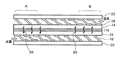
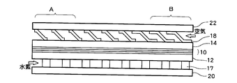
- FIG. 1 shows a cross-sectional configuration diagram of a fuel cell according to the present embodiment.
- the fuel cell includes a membrane electrode assembly (MEA) 10 in which an electrolyte membrane made of a solid polymer membrane is sandwiched between two electrodes, a fuel electrode and an air electrode, an anode side gas diffusion layer 12, and a cathode side gas diffusion.
- MEA membrane electrode assembly
- Layer 14 anode side gas flow path 16 formed in contact with anode side gas diffusion layer 12, cathode side gas flow path 18 formed in contact with cathode side gas diffusion layer 14, and separators 20 and 22. Consists of including.
- Both the anode side gas flow path 16 and the cathode side gas flow path 18 are made of expanded metal as a metal member. Hydrogen gas is supplied to the anode side gas flow path 16 as a fuel gas. Is supplied with air as an oxidant gas.
- the anode side gas channel 16 and the cathode side gas channel 18 are channels facing each other. That is, the hydrogen gas flow path in the anode side gas flow path 16 and the air flow path in the cathode side gas flow path 18 are opposite to each other. For example, as shown in the figure, the hydrogen gas flows from the left to the right in the figure in the anode side gas flow path 16, while the air flows from the right to the left in the figure in the cathode side gas flow path 18.
- the upstream side of the anode gas flow path 16 faces the downstream side of the cathode side gas flow path 18 with the MEA 10 in between, and the downstream side of the anode side gas flow path 16 has a cathode across the MEA 10 Opposite the upstream side of the side gas flow path 18.
- the area A in the figure is upstream of the anode side gas flow path 16 and corresponds to the downstream side of the cathode side gas flow path 18, and the area B in the figure is downstream of the anode side gas flow path 16. In addition, it corresponds to the upstream side of the cathode side gas flow path 18.
- the hydrogen gas is supplied to the anode side electrode through the anode side gas flow path 16 and is decomposed into electrons and hydrogen ions by the catalytic action of the electrode.
- the electrons move through the external circuit to the cathode side electrode.
- hydrogen ions pass through the MEA 10 and reach the cathode electrode, and are combined with oxygen contained in the air and electrons that have passed through the external circuit to become reaction water.
- the generated water is pushed out by the air channel and flows from the upstream side to the downstream side of the air channel. Therefore, it is easy to dry up on the upstream side of the cathode side flow path 18 and to be flooded on the downstream side of the cathode side gas flow path 18.
- the contact area on the downstream side of the cathode side gas flow path 18 is set to the upstream side. It is relatively smaller than the contact area.
- the contact area on the downstream side of the anode side gas flow path 16 is defined as the contact area on the upstream side. Make it relatively smaller.
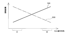
- FIG. 2 the change in the in-cell direction of the contact area of the expanded metal constituting the cathode side gas flow path 18 with the cathode side gas diffusion layer 14 in the present embodiment, and the expand constituting the anode side gas flow path 16 are shown.
- the change in the cell in-plane direction of the contact area with the anode side gas diffusion layer 12 of metal is shown.
- the change in the contact area of the expanded metal constituting the cathode side gas flow path 18 is indicated by a solid line 100
- the change in the contact area of the expanded metal constituting the anode side gas flow path 16 is indicated by an alternate long and short dash line 200.
- the contact area of the expanded metal constituting the cathode side gas flow path 18 changes so as to continuously decrease from the upstream side to the downstream side of the cathode side gas flow path 18 with respect to the cell in-plane direction.
- the contact area of the expanded metal constituting the cathode side gas flow path 18 decreases linearly from the right (upstream) to the left (downstream) in the figure.
- the contact area of the expanded metal constituting the anode side gas flow path 16 changes so as to continuously decrease from the upstream side to the downstream side of the anode side gas flow path 16.
- the contact area of the expanded metal constituting the anode-side gas flow path 16 decreases linearly from the left (upstream) to the right (downstream) in the figure.
- the contact area of the expanded metal constituting the cathode side gas flow path 18 is relatively small on the downstream side of the cathode side gas flow path 18, while the expanded metal constituting the anode side gas flow path 16. Is relatively large on the upstream side of the anode-side flow path 16, the contact area of the expanded metal constituting the cathode-side gas flow path 18 is the contact area of the expanded metal constituting the anode-side gas flow path 16. Is relatively smaller.
- the contact area of the expanded metal constituting the cathode side gas flow path 18 is relatively large on the upstream side of the cathode side gas flow path 16, while the expanded metal constituting the anode side gas flow path 16 is relatively large. Since the contact area is relatively small on the downstream side of the anode side gas flow path 16, the contact area of the expanded metal constituting the anode side gas flow path 16 is the contact area of the expanded metal constituting the cathode side gas flow path 18. Is relatively smaller.
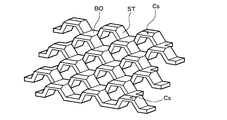
- FIG. 3 shows a perspective view of the expanded metal constituting the cathode side gas passage 18 and the anode side gas passage 16.
- Expanded metal is generally used as a member of the gas flow path of fuel cells, and sequentially processes staggered cuts on flat metal plates and pushes the cut cuts. By bending, a mesh-like small-diameter through-hole is formed, and further rolled into a substantially flat plate shape.
- the manufacturing method of the expanded metal is known, but in brief, a flat plate material is fed into a mold having a lower blade and an upper blade at a predetermined step width, and the trapezoidal convex portion of the upper blade and the base of the lower blade
- the flat plate material is partially sheared at regular intervals by the concave portion of the shape.
- a substantially flat expanded metal is manufactured by rolling a lath cut metal having a stepped mesh with a rolling roller.
- the expanded metal has a bond part BO and a strand part ST that connects the bond part BO to each other, and further, a contact surface Cs with the gas diffusion layer 12 (or 14) is formed.
- the contact surface Cs in the expanded metal is not the same and changes relatively between the upstream and downstream of the gas flow path.
- the contact area of the expanded metal changes as described above, a relative difference occurs in the cooling performance of the gas flow path. That is, the expanded metal constituting the cathode side gas flow path 18 and the anode side gas flow path 16 has a function of taking away the heat generated by power generation, so that the contact area of the expanded metal directly affects its cooling function. When the expanded metal contact area is relatively large, the cooling performance is also relatively large.
- the contact area of the expanded metal constituting the cathode side gas flow path 18 is the contact area of the expanded metal constituting the anode side gas flow path 16.
- the cooling performance of the downstream side of the cathode side gas passage 18 is relatively smaller than that of the upstream side of the anode side gas passage 16. Accordingly, the temperature downstream of the cathode side gas flow path 18 is relatively higher in the downstream side of the cathode side gas flow path 18 than the upstream side of the anode side gas flow path 16.
- the contact area of the expanded metal constituting the cathode side gas flow path 18 is the contact of the expanded metal constituting the anode side gas flow path 16.
- the cooling performance is large because it is relatively larger than the area. Therefore, the temperature downstream of the anode side gas flow path 16 is relatively higher than that downstream of the cathode side gas flow path 18.
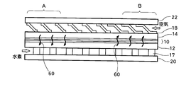
- FIG. 4 schematically shows the flow of generated water in this embodiment.
- the generated water generated on the cathode side with the power generation reaction is pushed out by the air flowing through the cathode side gas flow path 18 and flows downstream of the cathode side gas flow path 18 (A region in the figure). Since the downstream side of the cathode side gas passage 18 has a relatively higher temperature than the upstream side of the anode side gas passage 16, the generated water moves from the cathode side to the anode side via the MEA 10 due to this temperature gradient.
- an arrow 50 indicates the movement of the produced water from the cathode side to the anode side.
- the produced water that has moved to the anode side is pushed out by the hydrogen gas flowing through the anode side gas passage 16 and flows downstream of the anode side gas passage, that is, upstream of the cathode side gas passage (B region in the figure). Since the upstream side of the cathode side gas flow path 18 has a relatively lower temperature than the downstream side of the anode side gas flow path 16, the generated water moves from the anode side to the cathode side via the MEA 10 due to this temperature gradient. In the figure, an arrow 60 indicates the movement of product water from the anode side to the cathode side.
- the generated water is The upstream side of the cathode side gas flow path 18 ⁇ the downstream side of the cathode side gas flow path 18 ⁇ the upstream side of the anode side gas flow path 16 ⁇ the downstream side of the anode side gas flow path 16 ⁇ the upstream side of the cathode side gas flow path 18. Since the generated water is circulated and supplied to the cathode side gas flow path 18, flooding on the downstream side of the cathode side gas flow path 18 is suppressed, and dry-up on the upstream side of the cathode side gas flow path 18 is suppressed. Is suppressed. Note that not all of the generated water is circulated, and part of it is discharged to the outside from the cathode side.
- a relative temperature gradient is generated between the cathode side and the anode side by changing the contact area of the expanded metal, and thus the generated water is moved.
- the contact area is increased, the gas flow path and the water flow path are secured, so that the power generation performance is not deteriorated due to the narrowing of the gas flow path and the drain flow path.
- FIG. 5 schematically shows changes in the gas flow path and the drain flow path in accordance with the change in the contact area of the expanded metal.
- FIG. 5A shows a case where the contact area of the expanded metal of the cathode side gas flow path 18 and the anode side gas flow path 16 has a certain value
- FIG. 5B shows the expanded metal of the cathode side gas flow path 18. This shows a case where the contact area is increased.
- the expanded metal and the gas flow path 70 are separated from the drainage flow path 80, and water accumulates at the hydrophilic / hydrophilic interface between the expanded metal and the separators 20 and 22 to form the drainage flow path 80. It is understood that even if the contact area of the expanded metal is increased to improve the cooling performance, neither the gas flow path 70 nor the drainage flow path 80 is secured without being narrowed.
- FIG. 6 shows the moisture distribution in the cell plane direction in the present embodiment.
- a solid line 300 indicates the moisture content distribution in the present embodiment.
- a broken line 400 shows a moisture content distribution when the contact area of the expanded metal constituting the cathode side gas flow path 18 and the anode side gas flow path 16 is constant for comparison.
- the contact area is constant, the moisture content is drastically reduced on the upstream side (B region in the figure) of the cathode side gas flow path 18 and dry-up occurs. Further, the amount of water is relatively greater on the downstream side of the cathode side gas flow path than on the upstream side.
- FIG. 7 shows the relationship between the cell temperature and the cell voltage (output voltage) in this embodiment.
- a solid line 500 indicates a change in cell voltage in the present embodiment.
- a broken line 600 indicates a change in cell voltage when the contact area of the expanded metal constituting the cathode side gas flow path 18 and the anode side gas flow path 16 is constant for comparison.
- the contact area is constant, if the temperature increases to nearly 90 degrees, the proton conductivity of the electrolyte membrane decreases due to the effect of dry-up and the power generation efficiency decreases, so the cell voltage also decreases.
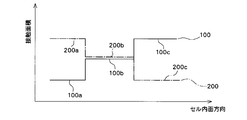
- FIG. 8 shows changes in the contact area of the expanded metal in the cell in-plane direction in the present embodiment.
- a solid line 100 indicates a change in the contact area of the expanded metal constituting the cathode side gas flow path 18, and the contact area increases stepwise from the downstream side to the upstream side of the cathode side gas flow path 18. That is, the cathode-side gas flow path 18 is divided into a downstream area, a middle flow area, and an upstream area, and in each divided area, the contact area is set to a constant value, Contact area 100a in the downstream area ⁇ Contact area 100b in the middle stream area ⁇ Contact area 100c in the upstream area Set to be.
- a broken line 200 is a change in the contact area of the expanded metal constituting the anode side gas flow path 16, and from the downstream side to the upstream side of the cathode side gas flow path 18 (that is, from the upstream side of the anode side flow path 16.
- the contact area decreases stepwise (towards the downstream side). That is, the anode-side gas flow path is divided into three areas, a downstream area, a midstream area, and an upstream area, and in each divided area, the contact area is set to a constant value, Contact area 200a in the downstream area> Contact area 200b in the middle stream area> Contact area 200c in the upstream area Set to be.
- the contact area of the expanded metal is relatively larger in the anode side gas flow path 16 than in the cathode side gas flow path 18 downstream of the cathode side gas flow path 18. Due to the size relationship, the temperature of the cathode gas channel 18 is relatively higher than that of the anode gas channel 16. Therefore, the generated water pushed out downstream of the cathode side gas flow path 18 moves to the anode side via the MEA 10 due to this temperature gradient.
- the contact area of the expanded metal is relatively larger in the cathode side gas flow path 18 than in the anode side gas flow path 16, and the relative size relationship of this contact area is increased. Due to the above, the temperature of the anode side gas passage 16 is relatively higher than that of the cathode side gas passage 18. Therefore, the generated water pushed to the downstream side of the anode side gas flow path 16 moves to the cathode side via the MEA 10 due to this temperature gradient.
- the generated water circulates upstream of the cathode side gas flow path 18 to suppress flooding downstream of the cathode side gas flow path 18 and to suppress dry up upstream of the cathode side gas flow path 16. Is done.
- the cathode side gas flow path 18 and the anode side gas flow path 16 are both made of expanded metal, but it is the cathode side that drainage becomes a problem.
- the cathode side gas flow path 18 may be composed of expanded metal, while the anode side may be composed of irregularities or grooves formed on the surface of the separator 20 other than the expanded metal.
- FIG. 9 shows a cross-sectional configuration of the fuel battery cell in the present embodiment.
- the fuel cell includes a membrane electrode assembly (MEA) 10 in which an electrolyte membrane made of a solid polymer membrane is sandwiched between two electrodes, a fuel electrode and an air electrode, an anode side gas diffusion layer 12, and a cathode side gas diffusion.
- MEA membrane electrode assembly
- the layer 14 is configured to include an anode side gas flow path 17, a cathode side gas flow path 18, and separators 20 and 22.
- the cathode side gas flow path 18 is composed of expanded metal. Further, the anode side gas flow path 17 is constituted by irregularities or grooves formed on the surface of the separator 20. The convex portion of the groove is in contact with the anode side gas diffusion layer 12 and functions as a rib for the MEA 10 or the anode side gas diffusion layer 12. Therefore, below, the member which comprises the anode side gas flow path 17 is suitably called a rib.
- the cathode side gas flow path 18 is supplied with air as an oxidant gas. Further, hydrogen gas is supplied to the anode side gas passage 17 as a fuel gas.
- the cathode side gas passage 18 (air passage) and the anode side gas passage 17 (hydrogen gas passage) face each other. That is, the air channel and the hydrogen gas channel are opposite to each other, the upstream of the air channel corresponds to the downstream of the hydrogen gas channel, and the downstream of the air channel corresponds to the upstream of the hydrogen gas channel.
- the contact area of the expanded metal constituting the cathode side gas flow path 18 with the cathode side gas diffusion layer 14 is relatively larger on the upstream side than on the downstream side.
- the contact area of the ribs constituting the anode side gas flow path 17 is relatively larger on the upstream side than on the downstream side. Since the upstream side of the anode gas flow path 17 corresponds to the downstream side of the cathode side gas flow path 18 and the downstream side of the anode side gas flow path 17 corresponds to the upstream side of the cathode side gas flow path 18, the flow of the cathode side gas flow path 18. Is the reference, the contact area of the rib is relatively larger on the downstream side than on the upstream side.
- the contact area of the rib of the anode side gas flow path 17 is relatively larger than the contact area of the expanded metal of the cathode side gas flow path 18.
- the cathode side gas passage 18 has a relatively higher temperature than the anode side gas passage 17.
- the contact area of the expanded metal in the cathode side gas flow path 18 is relatively larger than the contact area of the ribs in the anode side gas flow path 17.
- the anode side gas flow path 17 becomes relatively higher in temperature than the cathode side gas flow path 18.
- the generated water generated on the cathode side due to the power generation reaction is The upstream side of the cathode side gas channel 18 ⁇ the downstream side of the cathode side gas channel 18 ⁇ the upstream side of the anode side gas channel 17 ⁇ the downstream side of the anode side gas channel 17 ⁇ the upstream side of the cathode side gas channel 18. Since the generated water is circulated and supplied to the cathode side gas flow path 18, flooding on the downstream side of the cathode side gas flow path 18 is suppressed, and dry-up on the upstream side of the cathode side gas flow path 18 is suppressed. Is suppressed.
- both the cathode side gas flow path 18 and the anode side gas flow path 16 are made of expanded metal
- the cathode side gas flow path 18 is made of expanded metal
- the anode side gas flow path 17 is constituted by irregularities or grooves.
- the cathode side gas flow path and the anode side gas flow path are opposed to each other, and the cathode side gas flow path and the anode side gas flow path are both uneven. Or it can also comprise a groove.
- the temperature gradient is formed by changing the contact area of the ribs in the respective flow paths.
- the contact area of the expanded metal or the contact area of the rib is changed, but the contact rate (contact rate) may be changed instead of the contact area.
- the contact rate is the ratio of the area in contact with the gas diffusion layer in the surface area at the interface with the expanded metal or the uneven gas diffusion layer constituting the gas flow path.
- a temperature gradient is formed using the difference in contact rate between the cathode side gas flow path 18 and the anode side gas flow path 16 (or 17) to move the generated water.
- the contact rate between the cathode side gas flow path 18 and the anode side gas flow path 16 (or 17) is, for example, in the region A of FIG.
- Cathode side gas flow path 18 8-10%
- Anode side gas flow path 16 15-20% It only has to be about.
- the difference in contact ratio is preferably 7% or more, but is not necessarily limited thereto.
- the applicant of the present application moves the generated water to the opposite flow path via the MEA 10 if there is a difference in contact rate of at least 1% between the anode side gas flow path 18 and the cathode side gas flow path 16 (or 17). Make sure you do.
- the expanded metal is exemplified as the member constituting the cathode side gas flow path 18, but the present invention is not limited to this, and an expanded metal or other metal member, more specifically, a metal porous body is used. Can be used.
- the generated water is circulated in the opposed flow path and supplied upstream of the cathode-side gas flow path, so that a high-temperature non-humidification operation is possible, but a humidification operation may be performed as necessary. Needless to say, humidification operation is not excluded. However, since the humidification operation is not required by performing the non-humidification operation, the cost is reduced correspondingly, which is particularly suitable for mass production.
- the fuel cell of this embodiment can be mounted on a vehicle such as an electric vehicle or a fuel cell vehicle, but is not necessarily limited to a vehicle.
- MEA 10 MEA, 12 anode side gas diffusion layer, 14 cathode side gas diffusion layer, 16, 17 anode side gas flow path, 18 cathode side gas flow path, 20, 22 separator.
Landscapes
- Life Sciences & Earth Sciences (AREA)
- Engineering & Computer Science (AREA)
- Manufacturing & Machinery (AREA)
- Sustainable Development (AREA)
- Sustainable Energy (AREA)
- Chemical & Material Sciences (AREA)
- Chemical Kinetics & Catalysis (AREA)
- Electrochemistry (AREA)
- General Chemical & Material Sciences (AREA)
- Fuel Cell (AREA)
- Inert Electrodes (AREA)
Abstract
Priority Applications (6)
| Application Number | Priority Date | Filing Date | Title |
|---|---|---|---|
| EP11824332.8A EP2680354B1 (fr) | 2011-02-21 | 2011-02-21 | Pile à combustible |
| CN201180011027.5A CN102782918B (zh) | 2011-02-21 | 2011-02-21 | 燃料电池 |
| JP2011538742A JP5408263B2 (ja) | 2011-02-21 | 2011-02-21 | 燃料電池 |
| KR1020127013198A KR101347770B1 (ko) | 2011-02-21 | 2011-02-21 | 연료전지 |
| PCT/JP2011/053694 WO2012114432A1 (fr) | 2011-02-21 | 2011-02-21 | Pile à combustible |
| US13/697,280 US20130052551A1 (en) | 2011-02-21 | 2011-02-21 | Fuel cell |
Applications Claiming Priority (1)
| Application Number | Priority Date | Filing Date | Title |
|---|---|---|---|
| PCT/JP2011/053694 WO2012114432A1 (fr) | 2011-02-21 | 2011-02-21 | Pile à combustible |
Publications (1)
| Publication Number | Publication Date |
|---|---|
| WO2012114432A1 true WO2012114432A1 (fr) | 2012-08-30 |
Family
ID=46720253
Family Applications (1)
| Application Number | Title | Priority Date | Filing Date |
|---|---|---|---|
| PCT/JP2011/053694 Ceased WO2012114432A1 (fr) | 2011-02-21 | 2011-02-21 | Pile à combustible |
Country Status (6)
| Country | Link |
|---|---|
| US (1) | US20130052551A1 (fr) |
| EP (1) | EP2680354B1 (fr) |
| JP (1) | JP5408263B2 (fr) |
| KR (1) | KR101347770B1 (fr) |
| CN (1) | CN102782918B (fr) |
| WO (1) | WO2012114432A1 (fr) |
Cited By (2)
| Publication number | Priority date | Publication date | Assignee | Title |
|---|---|---|---|---|
| WO2016157320A1 (fr) * | 2015-03-27 | 2016-10-06 | 日産自動車株式会社 | Système de pile à combustible et procédé de commande de système de pile à combustible |
| CN107810572A (zh) * | 2015-07-03 | 2018-03-16 | 株式会社Lg化学 | 隔板、其制造方法和包括隔板的燃料电池堆 |
Families Citing this family (10)
| Publication number | Priority date | Publication date | Assignee | Title |
|---|---|---|---|---|
| CA2840020C (fr) | 2011-07-05 | 2018-07-17 | Toyota Jidosha Kabushiki Kaisha | Pile a combustible comportant un separateur ayant des formes convexes et des formes concaves |
| WO2017007174A1 (fr) * | 2015-07-03 | 2017-01-12 | 주식회사 엘지화학 | Plaque de séparation, procédé permettant de fabriquer cette dernière, et empilement de piles à combustible comprenant cette dernière |
| KR101959469B1 (ko) * | 2015-07-31 | 2019-07-02 | 주식회사 엘지화학 | 분리판, 및 이를 포함하는 연료전지 스택 |
| KR102518538B1 (ko) * | 2016-12-16 | 2023-04-07 | 현대자동차주식회사 | 연료전지용 다공체 |
| CN109904480A (zh) * | 2017-12-07 | 2019-06-18 | 中国科学院大连化学物理研究所 | 一种带有新型流场结构的双极板 |
| WO2020056580A1 (fr) * | 2018-09-18 | 2020-03-26 | 上海旭济动力科技有限公司 | Trajet d'écoulement de guidage de fluide et pile à combustible ayant un trajet d'écoulement de guidage de fluide |
| CN109786765B (zh) * | 2018-12-25 | 2021-08-24 | 武汉船用电力推进装置研究所(中国船舶重工集团公司第七一二研究所) | 一种燃料电池金属阴极板表面微结构的成型方法 |
| JP7192759B2 (ja) * | 2019-12-24 | 2022-12-20 | トヨタ車体株式会社 | 燃料電池用セパレータ |
| CN111785987A (zh) * | 2020-07-29 | 2020-10-16 | 杭州祥博传热科技股份有限公司 | 双极板用流场式散热装置 |
| CN114597444A (zh) * | 2022-02-14 | 2022-06-07 | 浙江天能氢能源科技有限公司 | 一种阴极腔封闭的风冷燃料电池 |
Citations (9)
| Publication number | Priority date | Publication date | Assignee | Title |
|---|---|---|---|---|
| JPH05251097A (ja) * | 1992-03-03 | 1993-09-28 | Fuji Electric Co Ltd | 固体高分子電解質型燃料電池 |
| JP2001006698A (ja) * | 1999-06-23 | 2001-01-12 | Fuji Electric Co Ltd | 固体高分子電解質型燃料電池と同燃料電池用拡散層の製造方法 |
| JP2004079245A (ja) * | 2002-08-12 | 2004-03-11 | Honda Motor Co Ltd | 燃料電池 |
| JP2006253038A (ja) * | 2005-03-11 | 2006-09-21 | Equos Research Co Ltd | セパレータユニット及び燃料電池スタック |
| JP2007035527A (ja) * | 2005-07-29 | 2007-02-08 | Equos Research Co Ltd | 集電体及びその製造方法 |
| JP2007305532A (ja) * | 2006-05-15 | 2007-11-22 | Canon Inc | 燃料電池 |
| JP2008140640A (ja) * | 2006-12-01 | 2008-06-19 | Kawamura Electric Inc | 燃料電池 |
| JP2009026476A (ja) * | 2007-07-17 | 2009-02-05 | Toyota Motor Corp | 燃料電池セル |
| JP2011018525A (ja) * | 2009-07-08 | 2011-01-27 | Toyota Motor Corp | 燃料電池および燃料電池システム |
Family Cites Families (6)
| Publication number | Priority date | Publication date | Assignee | Title |
|---|---|---|---|---|
| JP4312290B2 (ja) * | 1999-01-29 | 2009-08-12 | アイシン高丘株式会社 | 燃料電池及びセパレータ |
| JP2003217615A (ja) * | 2002-01-17 | 2003-07-31 | Toyota Motor Corp | 燃料電池のセパレータ |
| JP2006114387A (ja) * | 2004-10-15 | 2006-04-27 | Toyota Motor Corp | 燃料電池 |
| JP4915070B2 (ja) * | 2005-09-22 | 2012-04-11 | トヨタ車体株式会社 | 燃料電池用セパレータ |
| WO2008152794A1 (fr) * | 2007-06-08 | 2008-12-18 | Panasonic Corporation | Pile à combustible à électrolyte polymère |
| JP2008311047A (ja) * | 2007-06-14 | 2008-12-25 | Toyota Motor Corp | 燃料電池 |
-
2011
- 2011-02-21 WO PCT/JP2011/053694 patent/WO2012114432A1/fr not_active Ceased
- 2011-02-21 EP EP11824332.8A patent/EP2680354B1/fr not_active Not-in-force
- 2011-02-21 US US13/697,280 patent/US20130052551A1/en not_active Abandoned
- 2011-02-21 CN CN201180011027.5A patent/CN102782918B/zh not_active Expired - Fee Related
- 2011-02-21 KR KR1020127013198A patent/KR101347770B1/ko not_active Expired - Fee Related
- 2011-02-21 JP JP2011538742A patent/JP5408263B2/ja not_active Expired - Fee Related
Patent Citations (9)
| Publication number | Priority date | Publication date | Assignee | Title |
|---|---|---|---|---|
| JPH05251097A (ja) * | 1992-03-03 | 1993-09-28 | Fuji Electric Co Ltd | 固体高分子電解質型燃料電池 |
| JP2001006698A (ja) * | 1999-06-23 | 2001-01-12 | Fuji Electric Co Ltd | 固体高分子電解質型燃料電池と同燃料電池用拡散層の製造方法 |
| JP2004079245A (ja) * | 2002-08-12 | 2004-03-11 | Honda Motor Co Ltd | 燃料電池 |
| JP2006253038A (ja) * | 2005-03-11 | 2006-09-21 | Equos Research Co Ltd | セパレータユニット及び燃料電池スタック |
| JP2007035527A (ja) * | 2005-07-29 | 2007-02-08 | Equos Research Co Ltd | 集電体及びその製造方法 |
| JP2007305532A (ja) * | 2006-05-15 | 2007-11-22 | Canon Inc | 燃料電池 |
| JP2008140640A (ja) * | 2006-12-01 | 2008-06-19 | Kawamura Electric Inc | 燃料電池 |
| JP2009026476A (ja) * | 2007-07-17 | 2009-02-05 | Toyota Motor Corp | 燃料電池セル |
| JP2011018525A (ja) * | 2009-07-08 | 2011-01-27 | Toyota Motor Corp | 燃料電池および燃料電池システム |
Cited By (4)
| Publication number | Priority date | Publication date | Assignee | Title |
|---|---|---|---|---|
| WO2016157320A1 (fr) * | 2015-03-27 | 2016-10-06 | 日産自動車株式会社 | Système de pile à combustible et procédé de commande de système de pile à combustible |
| JPWO2016157320A1 (ja) * | 2015-03-27 | 2018-02-01 | 日産自動車株式会社 | 燃料電池システム及び燃料電池システムの制御方法 |
| US10020523B2 (en) | 2015-03-27 | 2018-07-10 | Nissan Motor Co., Ltd. | Fuel cell system and control method for fuel cell system |
| CN107810572A (zh) * | 2015-07-03 | 2018-03-16 | 株式会社Lg化学 | 隔板、其制造方法和包括隔板的燃料电池堆 |
Also Published As
| Publication number | Publication date |
|---|---|
| KR20120132466A (ko) | 2012-12-05 |
| JPWO2012114432A1 (ja) | 2014-07-07 |
| EP2680354A1 (fr) | 2014-01-01 |
| EP2680354B1 (fr) | 2017-07-05 |
| CN102782918A (zh) | 2012-11-14 |
| US20130052551A1 (en) | 2013-02-28 |
| KR101347770B1 (ko) | 2014-01-03 |
| JP5408263B2 (ja) | 2014-02-05 |
| CN102782918B (zh) | 2015-09-02 |
| EP2680354A4 (fr) | 2014-10-01 |
Similar Documents
| Publication | Publication Date | Title |
|---|---|---|
| JP5408263B2 (ja) | 燃料電池 | |
| US10847816B2 (en) | Fuel cell | |
| US10727511B2 (en) | Fuel cell | |
| JP6205915B2 (ja) | 燃料電池のガス流路形成部材及び燃料電池 | |
| US20140162175A1 (en) | Fuel cell and manufacturing method of expanded metal | |
| JP6604261B2 (ja) | 燃料電池 | |
| JP5768882B2 (ja) | 燃料電池 | |
| JP5429357B2 (ja) | 燃料電池 | |
| JP2020107397A (ja) | 燃料電池セル | |
| JP2013157315A (ja) | 燃料電池 | |
| JP6403099B2 (ja) | 燃料電池モジュール | |
| JP7048254B2 (ja) | 燃料電池 | |
| JP2008305755A (ja) | 燃料電池 | |
| JP2007134089A (ja) | 燃料電池 | |
| KR102610727B1 (ko) | 연료전지용 분리판 및 이를 포함하는 연료전지 | |
| JP5694093B2 (ja) | 燃料電池 | |
| JP2014182922A (ja) | 燃料電池スタック | |
| JP2008277211A (ja) | 燃料電池 | |
| JP2010232021A (ja) | 燃料電池 | |
| JP2013045570A (ja) | 燃料電池 | |
| JP2007273326A (ja) | 燃料電池セル | |
| JP2013257949A (ja) | 燃料電池 |
Legal Events
| Date | Code | Title | Description |
|---|---|---|---|
| WWE | Wipo information: entry into national phase |
Ref document number: 201180011027.5 Country of ref document: CN |
|
| WWE | Wipo information: entry into national phase |
Ref document number: 2011538742 Country of ref document: JP |
|
| REEP | Request for entry into the european phase |
Ref document number: 2011824332 Country of ref document: EP |
|
| WWE | Wipo information: entry into national phase |
Ref document number: 2011824332 Country of ref document: EP |
|
| ENP | Entry into the national phase |
Ref document number: 20127013198 Country of ref document: KR Kind code of ref document: A |
|
| 121 | Ep: the epo has been informed by wipo that ep was designated in this application |
Ref document number: 11824332 Country of ref document: EP Kind code of ref document: A1 |
|
| WWE | Wipo information: entry into national phase |
Ref document number: 13697280 Country of ref document: US |
|
| NENP | Non-entry into the national phase |
Ref country code: DE |