WO2012114451A1 - Appareil de conditionnement d'air, procédé de commande de fonctionnement d'appareil de conditionnement d'air, et système de refroidissement - Google Patents
Appareil de conditionnement d'air, procédé de commande de fonctionnement d'appareil de conditionnement d'air, et système de refroidissement Download PDFInfo
- Publication number
- WO2012114451A1 WO2012114451A1 PCT/JP2011/053780 JP2011053780W WO2012114451A1 WO 2012114451 A1 WO2012114451 A1 WO 2012114451A1 JP 2011053780 W JP2011053780 W JP 2011053780W WO 2012114451 A1 WO2012114451 A1 WO 2012114451A1
- Authority
- WO
- WIPO (PCT)
- Prior art keywords
- heat exchanger
- refrigerant
- temperature
- heat
- transfer medium
- Prior art date
- Legal status (The legal status is an assumption and is not a legal conclusion. Google has not performed a legal analysis and makes no representation as to the accuracy of the status listed.)
- Ceased
Links
Images



Classifications
-
- F—MECHANICAL ENGINEERING; LIGHTING; HEATING; WEAPONS; BLASTING
- F25—REFRIGERATION OR COOLING; COMBINED HEATING AND REFRIGERATION SYSTEMS; HEAT PUMP SYSTEMS; MANUFACTURE OR STORAGE OF ICE; LIQUEFACTION SOLIDIFICATION OF GASES
- F25B—REFRIGERATION MACHINES, PLANTS OR SYSTEMS; COMBINED HEATING AND REFRIGERATION SYSTEMS; HEAT PUMP SYSTEMS
- F25B41/00—Fluid-circulation arrangements
-
- F—MECHANICAL ENGINEERING; LIGHTING; HEATING; WEAPONS; BLASTING
- F25—REFRIGERATION OR COOLING; COMBINED HEATING AND REFRIGERATION SYSTEMS; HEAT PUMP SYSTEMS; MANUFACTURE OR STORAGE OF ICE; LIQUEFACTION SOLIDIFICATION OF GASES
- F25B—REFRIGERATION MACHINES, PLANTS OR SYSTEMS; COMBINED HEATING AND REFRIGERATION SYSTEMS; HEAT PUMP SYSTEMS
- F25B13/00—Compression machines, plants or systems, with reversible cycle
-
- F—MECHANICAL ENGINEERING; LIGHTING; HEATING; WEAPONS; BLASTING
- F25—REFRIGERATION OR COOLING; COMBINED HEATING AND REFRIGERATION SYSTEMS; HEAT PUMP SYSTEMS; MANUFACTURE OR STORAGE OF ICE; LIQUEFACTION SOLIDIFICATION OF GASES
- F25B—REFRIGERATION MACHINES, PLANTS OR SYSTEMS; COMBINED HEATING AND REFRIGERATION SYSTEMS; HEAT PUMP SYSTEMS
- F25B2313/00—Compression machines, plants or systems with reversible cycle not otherwise provided for
- F25B2313/027—Compression machines, plants or systems with reversible cycle not otherwise provided for characterised by the reversing means
- F25B2313/02741—Compression machines, plants or systems with reversible cycle not otherwise provided for characterised by the reversing means using one four-way valve
-
- F—MECHANICAL ENGINEERING; LIGHTING; HEATING; WEAPONS; BLASTING
- F25—REFRIGERATION OR COOLING; COMBINED HEATING AND REFRIGERATION SYSTEMS; HEAT PUMP SYSTEMS; MANUFACTURE OR STORAGE OF ICE; LIQUEFACTION SOLIDIFICATION OF GASES
- F25B—REFRIGERATION MACHINES, PLANTS OR SYSTEMS; COMBINED HEATING AND REFRIGERATION SYSTEMS; HEAT PUMP SYSTEMS
- F25B2400/00—Component parts or details not otherwise provided for in this subclass
- F25B2400/04—Refrigeration circuit bypassing means
- F25B2400/0401—Refrigeration circuit bypassing means for compressors
-
- F—MECHANICAL ENGINEERING; LIGHTING; HEATING; WEAPONS; BLASTING
- F25—REFRIGERATION OR COOLING; COMBINED HEATING AND REFRIGERATION SYSTEMS; HEAT PUMP SYSTEMS; MANUFACTURE OR STORAGE OF ICE; LIQUEFACTION SOLIDIFICATION OF GASES
- F25B—REFRIGERATION MACHINES, PLANTS OR SYSTEMS; COMBINED HEATING AND REFRIGERATION SYSTEMS; HEAT PUMP SYSTEMS
- F25B25/00—Machines, plants or systems, using a combination of modes of operation covered by two or more of the groups F25B1/00 - F25B23/00
- F25B25/005—Machines, plants or systems, using a combination of modes of operation covered by two or more of the groups F25B1/00 - F25B23/00 using primary and secondary systems
-
- F—MECHANICAL ENGINEERING; LIGHTING; HEATING; WEAPONS; BLASTING
- F25—REFRIGERATION OR COOLING; COMBINED HEATING AND REFRIGERATION SYSTEMS; HEAT PUMP SYSTEMS; MANUFACTURE OR STORAGE OF ICE; LIQUEFACTION SOLIDIFICATION OF GASES
- F25B—REFRIGERATION MACHINES, PLANTS OR SYSTEMS; COMBINED HEATING AND REFRIGERATION SYSTEMS; HEAT PUMP SYSTEMS
- F25B2500/00—Problems to be solved
- F25B2500/26—Problems to be solved characterised by the startup of the refrigeration cycle
Definitions
- the present invention relates to an air conditioner, an operation control method for the air conditioner, and a cooling system, and more particularly, to an air conditioner that performs natural circulation for circulating a refrigerant due to a difference in refrigerant density, an operation control method for the air conditioner, and a cooling system. .
- the air conditioner has a refrigeration cycle, and in a forced circulation cycle in which the refrigerant is circulated by the compressor, the refrigerant is driven by the compressor, flows into the condenser to be condensed and liquefied, decompressed by the expansion valve, The gas-liquid two-phase refrigerant flows into the evaporator and evaporates and cools.
- a natural circulation combined type air conditioner capable of a natural circulation cycle in which the refrigerant is naturally circulated by a difference in density of the refrigerant is known (see, for example, Patent Document 1).
- the refrigerant is driven by the density difference between the refrigerant liquid and the refrigerant gas, and the circulation amount of the refrigerant is affected by the height of the liquid column due to the refrigerant liquid formed on the evaporator inlet side.
- an air conditioner that performs a natural circulation cycle to start heat exchange (that is, to activate the natural circulation cycle)
- the influence of the indoor temperature, the outdoor temperature, and the refrigerant temperature in the natural circulation cycle is affected. receive.
- Patent Document 1 is known as a technique for improving the refrigerant shortage during the cooling operation by the refrigerant natural circulation cycle.
- Cooling operation by a natural circulation cycle is generally performed in an intermediate period (time when the outside air temperature is lower than the room temperature).
- ⁇ T 5 ° C.
- the refrigerant in the refrigerant circuit stored in the outdoor unit is kept at a pressure balanced with the outdoor temperature. For this reason, in order to start the cooling operation by natural circulation, it is necessary to shift the refrigerant in the refrigerant circuit to a predetermined pressure region not less than the pressure corresponding to the outdoor temperature and not more than the pressure corresponding to the indoor temperature.
- an object of the present invention is to provide an air conditioner, an operation control method for an air conditioner, and a cooling system that can stably and quickly start the natural circulation in a natural circulation cycle.
- the present invention is lower than the compressor, the first heat exchanger that exchanges heat with the first heat transfer medium on the heat source side, the expansion valve, and the first heat exchanger.
- a bypass pipe that bypasses the compressor is provided in an annular refrigerant circuit that is installed in a position and is sequentially connected to a second heat transfer medium on the use side and a second heat exchanger that performs heat exchange.
- An air conditioner capable of operating by switching between a natural circulation cycle for circulating a refrigerant according to a density difference between a heat exchanger, the expansion valve, and the second heat exchanger, and starting the natural circulation cycle
- the second heat transfer on the use side flowing into the second heat exchanger And characterized in that the flow rate of the body increases from the predetermined flow rate.
- an air conditioner an operation control method for an air conditioner, and a cooling system capable of stably and quickly starting the natural circulation in a natural circulation cycle.
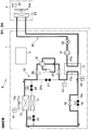
- FIG. 1 is a system diagram of an air conditioner S according to the present embodiment.
- the air conditioner S includes a refrigerant circuit 10 in which a refrigerant circulates, an outdoor unit 1 installed outside the room (outside the air-conditioned space), an indoor unit 3 installed inside the room (the air-conditioned space), and a control device 5. And.
- the air conditioner S has a function of performing “cooling operation” for cooling the room in which the indoor unit 3 is arranged and “heating operation” for heating the room in which the indoor unit 3 is arranged.
- the “cooling operation” includes a cooling operation by a forced circulation cycle in which the refrigerant in the refrigerant circuit 10 is circulated by the compressor 11 described later (hereinafter referred to as “cooling operation (forced circulation)”), and a refrigerant due to a difference in refrigerant density. It has a function of performing a cooling operation (hereinafter referred to as “cooling operation (natural circulation)”) by a natural circulation cycle in which the refrigerant of the circuit 10 is circulated.
- the air conditioner S also includes a refrigerant circuit 10 through which the refrigerant circulates and a heat transfer medium circulation circuit 30 through which the heat transfer medium circulates.
- the refrigerant circuit 10 provided in the outdoor unit 1 includes a compressor 11 that compresses the refrigerant into a high-pressure refrigerant, a four-way valve 12 that switches a refrigerant flow direction between a cooling operation and a heating operation, and an outdoor heat exchanger 13. And the auxiliary outdoor heat exchanger 14, the outdoor heat exchanger 13 and the outdoor fan 13a for blowing outdoor air to the auxiliary outdoor heat exchanger 14, the expansion valve 15 for reducing the pressure of the refrigerant, and the flow rate of the refrigerant.
- coolant flow control valve 16 the primary side fluid flow path 17a of the intermediate heat exchanger 17 which performs heat exchange with a heat transfer medium, electromagnetic valves 24 and 25, two-way valves 22 and 23, and the bypass valve 21 It is prepared for. These devices, valves, and the like are connected in an annular shape by a refrigerant pipe.
- the compressor 11 is a variable capacity compressor capable of capacity control.
- a compressor a piston type, a rotary type, a scroll type, a screw type, or a centrifugal type can be adopted.
- the compressor 11 is a scroll type compressor, and capacity control is possible by inverter control, and the rotational speed is variable from low speed to high speed.
- the outdoor heat exchanger 13 and the auxiliary outdoor heat exchanger 14 exchange heat between outdoor air as a heat source side heat medium blown from the outdoor fan 13a and refrigerant flowing in the heat exchangers 13 and 14.
- a fin tube type is used.
- the auxiliary outdoor heat exchanger 14 is connected in parallel to the outdoor heat exchanger 13, and is provided before and after the auxiliary outdoor heat exchanger 14 (upstream and downstream sides of the refrigerant flow during the cooling operation).
- By opening and closing the electromagnetic valves 24 and 25 it is possible to switch between the case where the refrigerant flows only to the outdoor heat exchanger 13 and the case where the refrigerant flows to both the outdoor heat exchanger 13 and the auxiliary outdoor heat exchanger 14. It has become.
- a bypass pipe 21a for bypassing the compressor 11 is provided, and a bypass valve 21 that is a two-way valve is attached to the bypass pipe 21a. Therefore, by controlling the opening and closing of the two-way valves 22 and 23 and the bypass valve 21 provided before and after the compressor 11, the flow path through which the refrigerant flows passes through the compressor 11 and bypasses the compressor 11. You can switch to and from.
- a bypass pipe 16a that bypasses the expansion valve 15 is provided, and a refrigerant flow control valve 16 is attached to the bypass pipe 16a. That is, the expansion valve 15 and the refrigerant flow control valve 16 are connected in parallel. Therefore, by controlling the opening / closing of the expansion valve 15 and the refrigerant flow control valve 16, the refrigerant can be selectively passed through the expansion valve 15 and the refrigerant flow control valve 16.
- the intermediate heat exchanger 17 performs heat exchange between the refrigerant flowing through the primary fluid flow path 17a and the heat transfer medium flowing through the secondary fluid flow path 17b.
- a vessel or the like is used.
- the intermediate heat exchanger 17 is installed at a position lower than the outdoor heat exchanger 13 and the auxiliary outdoor heat exchanger 14. This is for performing cooling operation by a natural circulation cycle.
- HFC refrigerant HFO-1234yf, HFO-1234ze, natural refrigerant (for example, CO 2 refrigerant), or the like can be used.
- natural refrigerant for example, CO 2 refrigerant
- a heat transfer medium circulation circuit 30 provided from the outdoor unit 1 to the indoor unit 3 includes a circulation pump 31 for feeding the heat transfer medium, a three-way valve 32, and an indoor heat exchanger 33 installed in the indoor unit 3. And an indoor fan 33a that blows indoor air to the indoor heat exchanger 33 and a secondary fluid flow path 17b of the intermediate heat exchanger 17 that performs heat exchange with the refrigerant are sequentially connected by a pipe, It is the circuit formed in.
- the indoor heat exchanger 33 performs heat exchange between indoor air as a use-side heat medium blown from the indoor fan 33a and a heat transfer medium flowing in the indoor heat exchanger 33.
- a fin tube The formula is used.
- the heat transfer medium flowing in the heat transfer medium circulation circuit 30 exchanges heat with the indoor air in the room where the indoor unit 3 is disposed via the indoor heat exchanger 33, thereby cooling or heating the room.
- the capacity adjustment of the indoor heat exchanger 33 is controlled by the rotational speed of the circulation pump 31, the opening degree of the three-way valve 32, and the rotational speed of the indoor fan 33a.
- water or brine (antifreeze) such as ethylene glycol can be used as the heat transfer medium.
- the air conditioning apparatus S includes a control device 5.
- the control device 5 determines the operation mode of the air conditioner S, and according to the determined operation mode, various valves (four-way valve 12, expansion valve 15, refrigerant flow rate control valve 16, bypass valve 21, two-way valves 22, 23, electromagnetic The state (opening) of the valves 24 and 25, the three-way valve 32), the rotational speed of the circulation pump 31, the rotational speed of the compressor 11, and the rotational speeds of the fans (outdoor fan 13a, indoor fan 33a) of each heat exchanger. It has the function to control and control various operations of the air conditioner S.
- the air conditioning apparatus S includes a temperature sensor 41 for detecting the outdoor temperature T OA, a temperature sensor 42 for detecting the indoor temperature T RM, a temperature sensor 43 for detecting an inlet refrigerant temperature T EVIN intermediate heat exchanger 17 And a temperature sensor 44 that detects the outlet refrigerant temperature TEVOUT of the intermediate heat exchanger 17, and the temperature detection signals detected by the temperature sensors 41, 42, 43, 44 are input to the control device 5.
- FIG. 2 is a system diagram illustrating the flow of the refrigerant and the heat transfer medium during the cooling operation (forced circulation) of the air-conditioning apparatus S according to the present embodiment.
- the control device 5 controls the refrigerant flow rate control valve 16, the bypass valve 21, the electromagnetic valve 24, and the electromagnetic valve 25 to be closed and the two-way valve 22 and the two-way valve 23 to be opened. To do.
- the control device 5 controls the opening (throttle) of the expansion valve 15 and controls the four-way valve 12 to be in the cooling operation position.
- the control device 5 controls the rotational speeds of the compressor 11 and the outdoor fan 13a.
- the auxiliary outdoor heat exchanger 14 stores excess refrigerant.
- the high-temperature and high-pressure refrigerant discharged from the compressor 11 flows into the outdoor heat exchanger 13 that functions as a condenser.
- the refrigerant flowing through the outdoor heat exchanger 13 dissipates heat by exchanging heat with the outdoor air sent by the outdoor fan 13a, and becomes a high-pressure liquid refrigerant.
- the liquid refrigerant that has flowed out of the outdoor heat exchanger 13 is depressurized by the expansion valve 15 and enters a low-temperature and low-pressure gas-liquid two-phase state. Then, the low-temperature and low-pressure refrigerant flows into the primary fluid passage 17a of the intermediate heat exchanger 17 that functions as an evaporator.
- the refrigerant flowing through the primary side fluid flow path 17a of the intermediate heat exchanger 17 is heated by the heat transfer medium by exchanging heat with the heat transfer medium flowing through the secondary side fluid flow path 17b of the intermediate heat exchanger 17. It evaporates and is sent to the compressor 11 and circulates through the refrigerant circuit 10.
- the control device 5 controls the rotational speeds of the circulation pump 31 and the indoor fan 33a.
- the control device 5 controls the opening degree of the three-way valve 32.
- the heat transfer medium cooled by flowing through the secondary fluid passage 17 b of the intermediate heat exchanger 17 flows into the indoor heat exchanger 33 of the indoor unit 3 by driving the circulation pump 31.
- the heat transfer medium flowing through the indoor heat exchanger 33 absorbs heat by exchanging heat with air (indoor air) sent by the indoor fan 33a. Then, the heat transfer medium that has absorbed heat is sent from the indoor heat exchanger 33 to the secondary fluid flow path 17b of the intermediate heat exchanger 17 and circulates in the heat transfer medium circulation circuit 30.
- the heat transfer medium absorbs heat in the indoor heat exchanger 33 of the indoor unit 3, whereby the air (room air) is cooled and the room (air-conditioned space) is cooled.
- the refrigerant is caused to flow in the opposite direction to that during the cooling operation (forced circulation) shown in FIG. That is, by switching the four-way valve 12 of the refrigerant circuit 10, the high-temperature and high-pressure refrigerant discharged from the compressor 11 is sent to the intermediate heat exchanger 17, and the intermediate heat exchanger 17 functions as a condenser. And it decompresses with the expansion valve 15, and the outdoor heat exchanger 13 functions as an evaporator.
- the heat transfer medium heated by the intermediate heat exchanger 17 flows into the indoor heat exchanger 33 and dissipates heat by exchanging heat with the air (indoor air) sent by the indoor fan 33a.
- the air-conditioned space is heated.
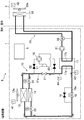
- FIG. 3 is a system diagram showing the flow of the refrigerant and the heat transfer medium during the cooling operation (natural circulation) of the air-conditioning apparatus S according to the present embodiment.
- the control device 5 performs control so that the expansion valve 15, the two-way valve 22, and the two-way valve 23 are closed and the bypass valve 21, the electromagnetic valve 24, and the electromagnetic valve 25 are opened.
- the control device 5 controls the opening degree of the refrigerant flow control valve 16.
- the control device 5 controls the rotational speed of the outdoor fan 13a.
- the compressor 11 is stopped.
- the auxiliary outdoor heat exchanger 14 functions as a condenser together with the outdoor heat exchanger 13.
- the refrigerant in the outdoor heat exchanger 13 and the auxiliary outdoor heat exchanger 14 functioning as a condenser dissipates heat to the outdoor air, condenses and liquefies.
- the liquid refrigerant having a high density descends under the influence of gravity, passes through the refrigerant flow rate control valve 16, and flows into the primary side fluid passage 17a of the intermediate heat exchanger 17 functioning as an evaporator.
- the refrigerant flowing through the primary fluid flow path 17a of the intermediate heat exchanger 17 absorbs heat from the heat transfer medium by exchanging heat with the heat transfer medium flowing through the secondary fluid flow path 17b of the intermediate heat exchanger 17. Evaporate and gasify.
- the heat transfer medium circulation circuit 30 is the same as the operation of the heat transfer medium circulation circuit 30 during the cooling operation (forced circulation), and a description thereof will be omitted.
- the indoor set temperature is 25 ° C. and the indoor / outdoor temperature difference that allows cooling operation (natural circulation) is 5 ° C., as shown in FIG.
- the outdoor temperature is below 20 ° C., especially around April, May, September and October, but natural circulation operation is possible even in winter when the indoor heat load is high.
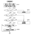
- step S ⁇ b> 101 the control device 5 drives the outdoor fan 13 a of the outdoor unit 1, takes outdoor air into the outdoor unit 1, and detects the outdoor temperature TOA with the temperature sensor 41. Further, the control device 5 drives the indoor fan 33 a of the indoor unit 3 to take in indoor air into the indoor unit 3, and detects the indoor temperature TRM with the temperature sensor 42. Moreover, the control apparatus 5 acquires set temperature TRPS which is indoor target temperature. The set temperature TRPS is input to the control device 5 when the user operates a remote controller (not shown) installed indoors, for example.
- step S102 the control unit 5 determines whether the indoor temperature T RM is higher than the set temperature T RPS. If the indoor temperature T RM is higher than the set temperature T RPS (S102 ⁇ Yes), the processing of the control unit 5 proceeds to step S104. When the room temperature T RM is not higher than the set temperature T RPS (No in S102), the process of the control device 5 proceeds to Step S103.
- step S103 the control device 5 performs the heating operation (forced circulation) of the air conditioner S.
- the heating operation forced circulation
- step S104 the controller 5 is the temperature difference between the room temperature T RM and the outdoor temperature T OA (T RM -T OA) is equal to or greater than a predetermined value PS1. If the temperature difference (T RM -T OA) is larger than the predetermined value PS1 (S104 ⁇ Yes), the processing of the control unit 5 proceeds to step S105. When the temperature difference (T RM ⁇ T OA ) is not greater than the predetermined value PS1 (No in S104), the process of the control device 5 proceeds to Step S106.
- step S105 the control device 5 determines whether or not the temperature difference (T RM ⁇ T RPS ) between the room temperature T RM and the set temperature T RPS is greater than a predetermined value PS2.
- the process of the control device 5 proceeds to step S107.
- the process of the control device 5 proceeds to Step S106.
- step S106 the control device 5 performs the cooling operation (forced circulation) of the air conditioner S.
- the cooling operation forced circulation
- step S107 the control device 5 determines whether or not the operation mode (previous operation mode) before the air conditioner S is stopped is the cooling operation (natural circulation).
- the process of the control device 5 proceeds to step S109 in FIG.
- the process of the control device 5 proceeds to Step S108.
- step S108 the control device 5 performs a switching operation to the cooling operation (natural circulation). The switching operation will be described later with reference to FIG. Then, the process of the control device 5 proceeds to step S109 in FIG.
- step S ⁇ b> 109 the control device 5 detects the inlet refrigerant temperature T EVIN of the intermediate heat exchanger 17 with the temperature sensor 43. Further, the control device 5 calculates the pressure ratio K.
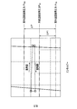
- FIG. 7 is an example of a diagram illustrating a relationship between pressure and enthalpy during cooling operation (natural circulation).
- the control unit 5, based on the indoor temperature T RM calculates the room temperature reference pressure P RM.
- the control unit 5, based on the outdoor temperature T OA calculates the outdoor temperature reference pressure P OA.
- the control unit 5, based on the inlet coolant temperature T EVIN calculates the refrigerant temperature reference pressure P ref.
- the indoor temperature reference pressure P RM is the pressure of the refrigerant when the refrigerant in the refrigerant circuit 10 is the indoor temperature T RM, and is calculated based on the physical property value of the refrigerant enclosed in the refrigerant circuit 10.
- the outdoor temperature reference pressure POA is the pressure of the refrigerant when the refrigerant in the refrigerant circuit 10 is the outdoor temperature TOA, and is calculated based on the physical property value of the refrigerant sealed in the refrigerant circuit 10.
- the refrigerant temperature reference pressure P ref a pressure corresponding to the current refrigerant temperature in the refrigerant circuit 10, as the reference temperature, a pressure of the refrigerant example at the inlet refrigerant temperature T EVIN intermediate heat exchanger 17, the refrigerant It is calculated based on the physical property value of the refrigerant sealed in the circuit 10. Then, as shown in FIG. 7, the pressure difference (P RM ⁇ P OA ) between the indoor temperature reference pressure P RM and the outdoor temperature reference pressure P OA is ⁇ P, and the refrigerant temperature reference pressure P ref and the outdoor temperature reference pressure P OA are set. And the pressure ratio K is ⁇ P1 / ⁇ P, the controller 5 calculates the pressure ratio K.
- the pressure difference (P ref ⁇ P OA ) is ⁇ P1.
- step S110 the control device 5 determines whether or not the pressure ratio K calculated in step S109 is equal to or greater than a predetermined value PS3.
- the pressure ratio K is equal to or greater than the predetermined value PS3 (S110 ⁇ Yes)
- the process of the control device 5 proceeds to step S115.
- the pressure ratio K is not equal to or greater than the predetermined value PS3 (S110 ⁇ No)
- the process of the control device 5 proceeds to step S111.
- step S111 the control device 5 outputs a startup operation command for cooling operation (natural circulation).
- the start-up operation is a start-up operation for quickly starting the cooling operation (natural circulation), and specifically, processing from step S112 to step S114 described later.
- step S112 the control device 5 opens the expansion valve 15 and closes the opening of the refrigerant flow rate control valve 16.
- the expansion valve 15 is closed and the opening of the refrigerant flow control valve 16 is reduced.
- the rotational speed of the circulation pump 31 is increased to increase the flow rate of the circulating heat transfer medium.
- the three-way valve 32 is switched so that the amount of the heat transfer medium circulating between the intermediate heat exchanger 17 and the indoor heat exchanger 33 increases.
- the processing of the control device 5 proceeds to step S116.
- the process of the control device 5 returns to Step S113.
- step S115 the control device 5 determines that the start-up operation is unnecessary. Then, the process of the control device 5 proceeds to step S116.
- step S116 the control device 5 sets the opening of the refrigerant flow control valve 16 to flow control (or full open). Further, the rotational speed of the circulation pump 31 is driven at the rated speed of the cooling operation (natural circulation). The same applies to the three-way valve 32.
- step S117 the control device 5 starts the cooling operation (natural circulation) of the air conditioner S.
- step S201 the control device 5 closes the refrigerant flow control valve 16, the two-way valve 22, and the two-way valve 23.
- the bypass valve 21, the electromagnetic valve 24, and the electromagnetic valve 25 are closed, and the expansion valve 15 is opened.
- step S202 the control device 5 changes the opening degree of the electromagnetic valve 25.
- the liquid refrigerant stored in the auxiliary outdoor heat exchanger 14 is discharged from the electromagnetic valve 25 through the expansion valve 15 to the inlet side of the intermediate heat exchanger 17, and to the inlet side of the intermediate heat exchanger 17.
- a coolant liquid column is formed.
- step S203 the control device 5 determines the refrigerant pressure in the region sandwiched between the solenoid valve 24 and the solenoid valve 25 (refrigerant pressure in the auxiliary outdoor heat exchanger 14) and the refrigerant pressure in the other refrigerant circuits 10 (for example, , The pressure difference between the refrigerant and the pressure of the refrigerant in the outdoor heat exchanger 13 is detected, and it is determined whether the pressure difference is within a specified value. Each pressure is detected by a pressure sensor (not shown). When the pressure difference is within the specified value (S203 / Yes), the process of the control device 5 proceeds to step S204. When the pressure difference is not within the specified value (No at S203), the process of the control device 5 returns to Step S202. Thus, the opening degree of the solenoid valve 25 is changed until the pressure difference is within the specified value, and the refrigerant stored in the auxiliary outdoor heat exchanger 14 is released.
- step S ⁇ b> 204 the control device 5 fully opens the solenoid valves 24 and 25.
- step S205 the control device 5 opens the bypass valve 21. And the process of the control apparatus 5 complete
- the air conditioner S increases the rotational speed of the circulation pump 31 and increases the flow rate of the heat transfer medium flowing into the intermediate heat exchanger 17 in the start-up operation.
- heat exchange between the refrigerant and the heat transfer medium in the intermediate heat exchanger 17 is promoted, and the refrigerant is quickly heated by the heat transfer medium.
- the pressure of the refrigerant in the refrigerant circuit 10 is also increased, and can be quickly shifted to a pressure region where natural circulation is possible.
- the heating amount is determined by the amount of refrigerant enclosed in the cycle, the heat capacity of the equipment constituting the cycle, and the like.
- the air conditioning apparatus S which concerns on this embodiment starts the cooling operation by a natural circulation cycle rapidly, and air-conditions a room
- the start-up time can be shortened and energy saving is improved.
- the air conditioner S restricts the opening by the expansion valve 15 and the refrigerant flow rate control valve 16 in the start-up operation, so that the inlet side of the intermediate heat exchanger 17 Since the refrigerant liquid column can be formed in the cooling operation, it is possible to easily start the cooling operation by the natural circulation cycle.
- the air conditioning apparatus S which concerns on this embodiment complete
- DELTA inlet-outlet temperature difference
- PS4 predetermined value
- the refrigerant evaporates and gasifies, and flows from the outlet side of the intermediate heat exchanger 17 to the outdoor heat exchanger 13 and the auxiliary outdoor heat exchanger 14 through the bypass pipe 21a.
- the air conditioning apparatus S which concerns on this embodiment is not limited to the structure of the said embodiment, A various change is possible within the range which does not deviate from the meaning of invention.
- the auxiliary refrigerant is stored in the cooling operation by the forced circulation cycle and the auxiliary outdoor heat exchanger 14 that functions as a condenser in the cooling operation by the natural circulation cycle is provided.
- coolant supply apparatus (not shown) which adjusts the refrigerant
- the refrigerant is passed through the expansion valve 15 during the cooling operation by the forced circulation cycle, and the refrigerant is passed through the refrigerant flow control valve 16 during the cooling operation by the natural circulation cycle.
- the present invention is not limited to this, and may be constituted by one pressure reducing valve (or one refrigerant flow rate control valve).
- the air-conditioning apparatus S that supplies the heat transfer medium cooled by the intermediate heat exchanger 17 to the indoor heat exchanger 33 and cools (cools) the room (the air-conditioned space) has been described.
- the present invention is not limited to this, and the present invention may be applied to a chiller system (cooling system) that supplies a heat transfer medium cooled by the intermediate heat exchanger 17 to an apparatus (not shown).
- the time required for starting the cooling operation by the natural circulation cycle can be shortened, so that the present invention can also be applied to a device (for example, a data center) that can be left in a poorly cooled state.
- the intermediate heat exchanger 17 and the heat transfer medium circulation circuit 30 are provided, and the rotation speed of the circulation pump 31 for feeding the heat transfer medium is increased during start-up operation.
- the intermediate heat exchanger 17 and the heat transfer medium circulation circuit 30 are not provided, and the refrigerant is circulated through the indoor heat exchanger 33 instead of the intermediate heat exchanger 17.
- the rotational speed of 33a may be increased.
- the indoor heat exchanger 33 needs to be disposed at a position lower than the outdoor heat exchanger 13 in order to allow natural circulation of the refrigerant.
Landscapes
- Engineering & Computer Science (AREA)
- Physics & Mathematics (AREA)
- Mechanical Engineering (AREA)
- Thermal Sciences (AREA)
- General Engineering & Computer Science (AREA)
- Air Conditioning Control Device (AREA)
Abstract
La présente invention se rapporte à un appareil de conditionnement d'air, qui peut démarrer de façon stable et rapide une circulation naturelle dans un cycle de circulation naturelle, à un procédé de commande du fonctionnement de l'appareil de conditionnement d'air et à un système de refroidissement.
Un appareil de conditionnement d'air (S) peut fonctionner par la réalisation d'une commutation entre un cycle de circulation forcée, dans lequel un milieu de refroidissement circule entre un compresseur (11), un premier échangeur thermique (13), un détendeur (15) et un second échangeur thermique (17), et un cycle de circulation naturelle, dans lequel, à l'aide de différences de densité, le milieu de refroidissement circule parmi un tuyau de dérivation (21a), le premier échangeur thermique (13), le détendeur (15) et le second échangeur thermique (17). Au moment du démarrage du cycle de circulation naturelle, un volume d'écoulement d'un second milieu de transfert de chaleur côté utilisateur s'écoulant dans le second échangeur thermique (17) augmente plus qu'un volume d'écoulement prédéfini.
Priority Applications (2)
| Application Number | Priority Date | Filing Date | Title |
|---|---|---|---|
| PCT/JP2011/053780 WO2012114451A1 (fr) | 2011-02-22 | 2011-02-22 | Appareil de conditionnement d'air, procédé de commande de fonctionnement d'appareil de conditionnement d'air, et système de refroidissement |
| JP2013500747A JP5629366B2 (ja) | 2011-02-22 | 2011-02-22 | 空気調和装置、空気調和装置の運転制御方法および冷却システム |
Applications Claiming Priority (1)
| Application Number | Priority Date | Filing Date | Title |
|---|---|---|---|
| PCT/JP2011/053780 WO2012114451A1 (fr) | 2011-02-22 | 2011-02-22 | Appareil de conditionnement d'air, procédé de commande de fonctionnement d'appareil de conditionnement d'air, et système de refroidissement |
Publications (1)
| Publication Number | Publication Date |
|---|---|
| WO2012114451A1 true WO2012114451A1 (fr) | 2012-08-30 |
Family
ID=46720271
Family Applications (1)
| Application Number | Title | Priority Date | Filing Date |
|---|---|---|---|
| PCT/JP2011/053780 Ceased WO2012114451A1 (fr) | 2011-02-22 | 2011-02-22 | Appareil de conditionnement d'air, procédé de commande de fonctionnement d'appareil de conditionnement d'air, et système de refroidissement |
Country Status (2)
| Country | Link |
|---|---|
| JP (1) | JP5629366B2 (fr) |
| WO (1) | WO2012114451A1 (fr) |
Cited By (4)
| Publication number | Priority date | Publication date | Assignee | Title |
|---|---|---|---|---|
| CN111947336A (zh) * | 2020-08-24 | 2020-11-17 | 珠海格力电器股份有限公司 | 一种制冷循环系统及其控制方法 |
| CN112460863A (zh) * | 2020-12-10 | 2021-03-09 | 珠海格力电器股份有限公司 | 一种冷水机组及其制冷控制方法和装置 |
| CN114531822A (zh) * | 2022-01-12 | 2022-05-24 | 比赫电气(太仓)有限公司 | 一种密闭式冷却循环液冷系统及其工作方法 |
| US20230324082A1 (en) * | 2022-03-30 | 2023-10-12 | Seiko Epson Corporation | Positive displacement machine, compressor, cooling apparatus, and electronic equipment |
Citations (5)
| Publication number | Priority date | Publication date | Assignee | Title |
|---|---|---|---|---|
| JPH03160238A (ja) * | 1989-11-17 | 1991-07-10 | Takenaka Komuten Co Ltd | 冷媒自然循環式冷房システム |
| JPH08189713A (ja) * | 1995-01-13 | 1996-07-23 | Daikin Ind Ltd | 二元冷凍装置 |
| JPH09196476A (ja) * | 1996-01-17 | 1997-07-31 | Shinko Atomosu Kk | 冷媒循環システムの膨張弁の制御装置 |
| JPH11257767A (ja) * | 1998-03-16 | 1999-09-24 | Mitsubishi Electric Corp | 自然循環併用式空気調和機 |
| JP2000356430A (ja) * | 1999-06-16 | 2000-12-26 | Tokyo Gas Co Ltd | 水冷式空調装置およびその運転方法 |
Family Cites Families (2)
| Publication number | Priority date | Publication date | Assignee | Title |
|---|---|---|---|---|
| JPH0765778B2 (ja) * | 1986-11-04 | 1995-07-19 | ダイキン工業株式会社 | 熱移動装置 |
| JP3334601B2 (ja) * | 1998-04-03 | 2002-10-15 | 三菱電機株式会社 | 自然循環併用式空気調和機 |
-
2011
- 2011-02-22 JP JP2013500747A patent/JP5629366B2/ja not_active Expired - Fee Related
- 2011-02-22 WO PCT/JP2011/053780 patent/WO2012114451A1/fr not_active Ceased
Patent Citations (5)
| Publication number | Priority date | Publication date | Assignee | Title |
|---|---|---|---|---|
| JPH03160238A (ja) * | 1989-11-17 | 1991-07-10 | Takenaka Komuten Co Ltd | 冷媒自然循環式冷房システム |
| JPH08189713A (ja) * | 1995-01-13 | 1996-07-23 | Daikin Ind Ltd | 二元冷凍装置 |
| JPH09196476A (ja) * | 1996-01-17 | 1997-07-31 | Shinko Atomosu Kk | 冷媒循環システムの膨張弁の制御装置 |
| JPH11257767A (ja) * | 1998-03-16 | 1999-09-24 | Mitsubishi Electric Corp | 自然循環併用式空気調和機 |
| JP2000356430A (ja) * | 1999-06-16 | 2000-12-26 | Tokyo Gas Co Ltd | 水冷式空調装置およびその運転方法 |
Cited By (5)
| Publication number | Priority date | Publication date | Assignee | Title |
|---|---|---|---|---|
| CN111947336A (zh) * | 2020-08-24 | 2020-11-17 | 珠海格力电器股份有限公司 | 一种制冷循环系统及其控制方法 |
| CN111947336B (zh) * | 2020-08-24 | 2024-05-07 | 珠海格力电器股份有限公司 | 一种制冷循环系统及其控制方法 |
| CN112460863A (zh) * | 2020-12-10 | 2021-03-09 | 珠海格力电器股份有限公司 | 一种冷水机组及其制冷控制方法和装置 |
| CN114531822A (zh) * | 2022-01-12 | 2022-05-24 | 比赫电气(太仓)有限公司 | 一种密闭式冷却循环液冷系统及其工作方法 |
| US20230324082A1 (en) * | 2022-03-30 | 2023-10-12 | Seiko Epson Corporation | Positive displacement machine, compressor, cooling apparatus, and electronic equipment |
Also Published As
| Publication number | Publication date |
|---|---|
| JPWO2012114451A1 (ja) | 2014-07-07 |
| JP5629366B2 (ja) | 2014-11-19 |
Similar Documents
| Publication | Publication Date | Title |
|---|---|---|
| US9322562B2 (en) | Air-conditioning apparatus | |
| CN102365502B (zh) | 空气调节装置 | |
| US9140459B2 (en) | Heat pump device | |
| CN106030219B (zh) | 空气调节装置 | |
| JP5383816B2 (ja) | 空気調和装置 | |
| CN103080668B (zh) | 空气调节装置 | |
| JPWO2011048662A1 (ja) | ヒートポンプ装置 | |
| JP5300806B2 (ja) | ヒートポンプ装置 | |
| WO2012104891A1 (fr) | Dispositif de climatisation | |
| JP5908183B1 (ja) | 空気調和装置 | |
| JP6120943B2 (ja) | 空気調和装置 | |
| AU2011358039A1 (en) | Air-conditioning apparatus | |
| WO2015097787A1 (fr) | Climatiseur | |
| JP6486847B2 (ja) | 環境試験装置 | |
| JP5629366B2 (ja) | 空気調和装置、空気調和装置の運転制御方法および冷却システム | |
| CN103097832B (zh) | 空气调节装置 | |
| KR20120083139A (ko) | 히트펌프식 급탕장치 | |
| JP5639664B2 (ja) | 空気調和装置 | |
| JP5312681B2 (ja) | 空気調和装置 | |
| JP2008175430A (ja) | 空気調和機 | |
| JP4258426B2 (ja) | 冷凍サイクル装置 | |
| JP5005011B2 (ja) | 空気調和装置 | |
| JP5150300B2 (ja) | ヒートポンプ式給湯装置 | |
| KR20110117974A (ko) | 히트펌프식 급탕장치 | |
| JP2007183045A (ja) | ヒートポンプ式冷暖房装置 |
Legal Events
| Date | Code | Title | Description |
|---|---|---|---|
| 121 | Ep: the epo has been informed by wipo that ep was designated in this application |
Ref document number: 11859529 Country of ref document: EP Kind code of ref document: A1 |
|
| ENP | Entry into the national phase |
Ref document number: 2013500747 Country of ref document: JP Kind code of ref document: A |
|
| NENP | Non-entry into the national phase |
Ref country code: DE |
|
| 122 | Ep: pct application non-entry in european phase |
Ref document number: 11859529 Country of ref document: EP Kind code of ref document: A1 |