WO2012114457A1 - Dispositif d'émission d'informations de modèles analytiques et programme d'émission d'informations de modèles analytiques - Google Patents
Dispositif d'émission d'informations de modèles analytiques et programme d'émission d'informations de modèles analytiques Download PDFInfo
- Publication number
- WO2012114457A1 WO2012114457A1 PCT/JP2011/053846 JP2011053846W WO2012114457A1 WO 2012114457 A1 WO2012114457 A1 WO 2012114457A1 JP 2011053846 W JP2011053846 W JP 2011053846W WO 2012114457 A1 WO2012114457 A1 WO 2012114457A1
- Authority
- WO
- WIPO (PCT)
- Prior art keywords
- model
- shape
- cad
- unit
- analysis model
- Prior art date
- Legal status (The legal status is an assumption and is not a legal conclusion. Google has not performed a legal analysis and makes no representation as to the accuracy of the status listed.)
- Ceased
Links
Images


Classifications
-
- G—PHYSICS
- G06—COMPUTING OR CALCULATING; COUNTING
- G06T—IMAGE DATA PROCESSING OR GENERATION, IN GENERAL
- G06T17/00—Three-dimensional [3D] modelling for computer graphics
-
- G—PHYSICS
- G06—COMPUTING OR CALCULATING; COUNTING
- G06F—ELECTRIC DIGITAL DATA PROCESSING
- G06F30/00—Computer-aided design [CAD]
- G06F30/10—Geometric CAD
- G06F30/17—Mechanical parametric or variational design
Definitions
- the present invention relates to an analysis model information delivery apparatus and an analysis model information delivery program for delivering necessary information to an analyst when an analysis model of a design three-dimensional CAD model is created.
- the CAD data includes data on the first part and the second part. Then, a place where a weld bead is created is searched by the weld bead search unit, and the gap check unit checks the gap by comparing the angle formed by the first part and the second part with the inter-surface angle threshold value data. Based on this check result, the virtual shape creating unit creates a virtual shape in the gap, and based on the leg length data of the weld bead, the weld bead creating unit creates a weld bead in the virtual shape. When the welding operation is analyzed in this way, CAD data including the created weld bead is stored in the CAD data storage unit.
- Patent Document 2 when a model used by a designer is diverted, a design support program is provided for the basic shape used to facilitate the determination of application or non-application of the basic shape used in the model to be diverted. It has a basic shape extraction unit for extracting data, a know-how extraction unit for extracting know-how data, and an association degree setting unit for associating model data with know-how data.
- a design support program for the basic shape used to facilitate the determination of application or non-application of the basic shape used in the model to be diverted. It has a basic shape extraction unit for extracting data, a know-how extraction unit for extracting know-how data, and an association degree setting unit for associating model data with know-how data.
- the location where the first component and the second component are in contact with the CAD data is the location to be welded, and the first and second components are joined together.
- the part is automatically searched, the lines constituting the shared surface are presented to the user, and welding information is added.
- an analyst and a designer differ, there exists a possibility of adding the welding information which a designer does not intend and creating an incorrect analysis model.
- an analyst who is different from the designer may create an analysis model based on his / her own judgment without confirming the phenomenon and contents necessary for the design study. If the designer's intention is known after the analysis is executed, the analysis model needs to be corrected.
- the present invention has been made in view of the above problems of the prior art, and an object of the present invention is to enable an analysis model to be created quickly even when a designer and an analyst are different. Another object of the present invention is to reduce the occurrence of mistakes in creating an analysis model when the designer and the analyst are different.
- a feature of the present invention that achieves the above object is an analysis model information passing device provided in a device for creating a numerical analysis model from CAD data, a CAD data reading unit for reading CAD data and creating a three-dimensional CAD model, A shape retrieval unit that retrieves a shape feature from each element constituting the CAD data and stores it in a CAD feature shape database, and matches a result of the search performed by the shape retrieval unit with a shape creation rule stored in advance in an analysis modeling technique database
- An inquiry unit for instructing the input / output device to display and interactively correct the search result of the CAD data in response to the inquiry from the inquiry unit, and highlight the corrected portion of the corrected three-dimensional CAD model
- a numerical analysis model is created from the input result display unit instructing the input / output device and the corrected three-dimensional CAD model
- a Dell conversion unit a modeled location display unit that instructs the input / output device to display the corrected location highlighted on the numerical analysis model, and correction of the numerical analysis model displayed on the modeled location display unit
- the shape search unit and the shape processing unit may be provided in different servers.
- the name is extracted. It is desirable to provide a name search unit that is registered in the CAD feature shape database.
- the input result display unit displays the modified shape creation rule together with the 3D CAD model name. It is desirable to register in the analysis modeling technique database, and when the modeling location display unit instructs to highlight the correction location on the numerical analysis model, the correction location is different from other locations of the numerical analysis model. You may have a display means to display using a color.
- Another feature of the present invention is provided in an apparatus for creating a numerical analysis model from CAD data, and in an analysis model information delivery apparatus for retrieving a characteristic shape from three-dimensional CAD data, the three-dimensional CAD data is converted from the three-dimensional CAD data.
- Means for correcting the numerical analysis model in accordance with an input of the determination condition, and an analysis model information delivery device characterized by comprising:
- Still another feature of the present invention that achieves the above object is an analysis model information delivery program provided in an apparatus for creating a numerical analysis model from CAD data, and the computer reads the CAD data and creates a three-dimensional CAD model.
- a CAD data reading unit, a shape search unit for searching for a shape feature from each element constituting the CAD data and storing it in the CAD feature shape database, and a result of the search by the shape search unit are stored in advance in the analytical modeling technique database.
- An inquiry unit for instructing the input / output device to collate and present the generated shape creation rule, and interactively correct the search result of the CAD data in response to the inquiry from the inquiry unit, and the corrected three-dimensional CAD model
- An input result display section for instructing the input / output device to highlight the correction portion, and a corrected three-dimensional CAD module
- a model conversion unit that creates a numerical analysis model from a data base, a modeled location display unit that instructs the input / output device to highlight and display a corrected location on the numerical analysis model,
- the correction unit of the displayed numerical analysis model is made to function as a shape processing unit that interactively corrects the correction point.
- the CAD data reading unit, the shape search unit, and the input result display unit are a single program stored in one server, the model conversion unit, and the modeled location display.
- the shape processing unit may be a single program and stored in another server.
- the know-how of the designer can be transmitted to the analyst through a common server or program, so that even if the designer and the analyst are different, an analysis model is created in line with the intention of the designer, Analysis model creation can be corrected quickly and rework can be reduced, and analysis models can be created quickly.
- the analysis model is created in accordance with the intention of the designer, so that the occurrence of mistakes in the creation of the analysis model can be reduced.
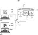
- FIG. 1 is a schematic diagram of a design support system including an analysis model information delivery apparatus according to the present invention.
- FIG. 2 is a block diagram of an embodiment of the analysis model information delivery apparatus according to the present invention.
- FIG. 3 is an operation flowchart of the analysis model information delivery apparatus shown in FIG.
- FIG. 4 is a specific operation flowchart of the analysis model information delivery apparatus shown in FIG.
- FIG. 5 is a diagram for explaining the contents of the CAD feature shape database shown in FIG.
- FIG. 6 is a diagram for explaining the contents of the analytical modeling technique database shown in FIG.
- FIG. 7 is a diagram illustrating an example of an operation screen used in the operation flow illustrated in FIG. 3.
- FIG. 8 is a diagram illustrating an example of an operation screen used in the operation flow illustrated in FIG. 3.
- FIG. 3 is an operation flowchart of the analysis model information delivery apparatus shown in FIG.
- FIG. 4 is a specific operation flowchart of the analysis model information delivery apparatus shown in FIG.
- FIG. 5 is a
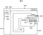
- FIG. 9 is a diagram showing an example of an operation screen used in the operation flow shown in FIG.
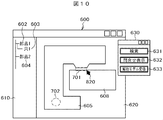
- FIG. 10 is a diagram illustrating an example of an operation screen used in the operation flow illustrated in FIG. 3.
- FIG. 11 is a diagram showing an example of an operation screen used in the operation flow shown in FIG.
- FIG. 12 is a diagram illustrating an example of an operation screen used in the operation flow illustrated in FIG.
- FIG. 13 is a diagram illustrating an example of an operation screen used in the operation flow illustrated in FIG. 3.
- FIG. 14 is a diagram showing an example of an operation screen used in the operation flow shown in FIG.
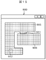
- FIG. 15 is a diagram illustrating an example of an operation screen used in the operation flow illustrated in FIG. 3.
- FIG. 16 is a diagram illustrating an example of an operation screen used in the operation flow illustrated in FIG. 3.
- FIG. 17 is a diagram illustrating an example of an operation screen used in the operation flow illustrated in FIG. 3.
- FIG. 1 is a schematic diagram of a design support system 50 including an analysis model information delivery device.
- the designer who creates the shape model and the analysis specialist who creates the analysis model and executes the analysis from this shape also use separate servers 30 and 40, respectively, via a network (communication line),
- the database stored in the storage device 140 having the capacity is shared.
- 3D CAD software is stored in the server 30 used by the designer and constitutes a CAD model creation unit 120.
- Analysis software is stored in the server 40 used by the analysis specialist, and constitutes an analysis CAD model reading unit 130.
- Each server 30, 40 has an input / output device 100, and includes a keyboard and mouse as input means and a display as input / output means.
- a LAN or the Internet is used as the network.
- the storage device 140 stores a CAD database 110 in which CAD data, which is the geometric shape of the design target part, is stored, a CAD feature shape database 111 and an analysis modeling technique database 112, which will be described in detail later.
- FIG. 2 is a block diagram showing an embodiment of the analysis model information delivery device 160 provided in the design support system 50 shown in FIG.
- the analysis model information delivery device 160 is a device shared by a designer who designs a part and an analysis specialist who performs numerical analysis based on a CAD model created by the designer. The designer used the design. The analyst may later use it for analysis, or the designer and analyst may use each other interactively.
- the analysis model information delivery device 160 is usually a software program, and is installed in one or more computers 150 that are arithmetic devices.
- the computer 150 is provided with the input / output device 100 shown in FIG. Further, the computer 150 is provided with a large-scale storage device 140 via the network 60 or directly.
- the storage device 140 stores the CAD database 110, the CAD feature shape database 111, and the analysis modeling technique database 112.
- the computing device 150 is roughly composed of a CAD model creation unit 120, an analysis CAD model reading unit 130, and a model conversion unit 107 interposed between the CAD model creation unit 120 and the analysis model reading unit 130.
- an analysis means for performing an actual analysis for example, a stress analysis or a flow analysis is naturally included in the arithmetic unit 150.
- the CAD model creation unit 120 includes a CAD data reading unit 101, a shape search unit 102, a name search unit 103, an inquiry unit 104, an answer input unit 105, and an input result display unit 106.
- the CAD data reading unit 101 reads CAD data from the CAD database 110 stored in the storage device 140 as input data, and creates a provisional three-dimensional CAD model.
- the shape retrieval unit 102 retrieves a characteristic shape such as a gap or a hole from the read CAD data.
- the shape search unit 102 searches for a hole shape as a characteristic shape based on the distance between surfaces in the CAD data.
- the CAD feature shape database 111 is searched based on the line information constituting the cylindrical surface and the arc.
- the name search unit 103 When the read CAD data is flagged as having a label for the feature name and the CAD data has some feature, the name search unit 103 has a complicated and detailed CAD model. Shapes that are difficult to search under the search conditions of the shape search unit 102 are extracted. Such a shape is also given to data in the CAD feature shape database 111 as label information of a part name / feature name (see FIG. 5C).
- the result of searching the CAD data read by the shape search unit 102 and the name search unit 103 is registered in the CAD feature shape database 111 and output as an output list.
- Each data in the output list is compared with determination conditions stored in advance in the analysis modeling technique database 112.
- the inquiry unit 104 included in the CAD model creation unit 120 inquires the designer (the user of the analysis model information delivery apparatus 160) about the determination considering the analysis conditions.
- the designer who is the current user of the analysis model information delivery device 160 inputs an answer to the inquiry content from the inquiry unit 104 from the answer input unit 105 of the CAD model creation unit 120 in an interactive input format.
- the input / output device 100 In the operation screen on the display provided, an inquiry screen is presented at the determination location in the three-dimensional CAD model created from the CAD data. In addition, the determination part is highlighted. Therefore, the designer who is the user inputs in interactive form whether or not the corresponding portion is a gap.
- the inquiry unit 104 inputs whether or not it is necessary to reproduce as a hole in an interactive model in an interactive format. Let The input result answered from the answer input unit 105 is reflected on the three-dimensional CAD model displayed on the display of the input / output device 100 via the input result display unit 106 of the CAD model creation unit 120. At that time, the corresponding portion of the three-dimensional CAD model is highlighted only in the minimum range.
- the information input via the response input unit 105 updates the CAD model as new CAD model data.
- the model conversion unit 107 provided in the arithmetic device 150 converts the three-dimensional CAD model into an analysis CAD model.
- the analysis CAD model obtained by converting the three-dimensional CAD model by the model conversion unit 107 is operated on the display of the input / output device 100 via the analysis model location display unit 108 included in the analysis CAD model reading unit 130. Displayed on the screen. At this time, the portion of the analysis CAD model corresponding to the location where the CAD model extracted from the CAD database 110 is updated or corrected is highlighted only in the minimum range.
- the analysis modeling method intended by the designer is interactively input to the analysis model information delivery device 160 and then delivered to an analysis specialist who uses the analysis model information delivery device 160.
- the analysis specialist performs analysis modeling by the shape processing unit 109 included in the analysis CAD model reading unit 130 while confirming the delivered information.
- FIG. 3 is a flowchart showing the operation of the analysis model information delivery device 160 shown in FIG. 2
- FIG. 4 is a flowchart showing the operation of the analysis model information delivery device 160 in a more specific example.
- a three-dimensional CAD model is created from CAD data stored in the CAD database 110, and a model conversion is performed on the created three-dimensional CAD model before an analysis model is created, and a place to be an analysis model is displayed. It shows how the above flow is executed on the premise that the analytical modeling method is applied. A part to which the analytical modeling technique is applied is searched, and the analytical modeling technique is set in the searched part. The location where the analysis modeling method is set is highlighted on the input / output device 100 via the analysis modeling location display unit 108.
- the CAD data reading unit 101 reads the CAD data as input data from the CAD database 110, and a provisional three-dimensional CAD model is formed (step S201).
- the analysis model information delivery apparatus 160 determines whether or not the shape of each part constituting the read CAD data or the three-dimensional CAD model is labeled. If it is determined that the CAD data to be analyzed is labeled, a feature search based on the label information is executed in the name search 203 for the read CAD data or the three-dimensional CAD model (step S203).
- step S202 When it is determined in step S202 that the shape of any part of the CAD data to be analyzed is not labeled, the read CAD data or the three-dimensional CAD model has a gap or a hole included in the CAD data.
- the shape search unit 102 searches for the feature of the shape (step S204).
- step S203 and step S204 are stored in the CAD feature shape database 111.
- the designer inputs a guideline for analysis modeling into the analysis modeling column of the CAD feature shape database 111 (see FIG. 5C) based on the search result.
- the determination conditions stored in advance in the analytical modeling technique database 112 are compared with the search results (S203, S04), and the comparison results are reflected in the CAD feature database 111 (step S205) (FIG. 3 is not shown).
- each feature is displayed on the display of the input / output device 100.
- the analysis modeling technique inquiry unit 104 displays the inquiry contents that change according to the type of analysis or the like (step S206).
- Step S207 The designer who is the user interactively inputs an answer to the inquiry content displayed on the input / output device 100.
- the answer result is input to an answer column (not shown) of the analysis modeling technique database 112.
- step S208 it is highlighted as an input result on the three-dimensional CAD model screen of the input / output device 100.
- the above steps S201 to S208 are mainly executed by the CAD model creating unit 120 (step A).
- step S207 The information set by the answer in step S207 is applied to the three-dimensional CAD model. This is called embedding.
- step S209 the finally determined three-dimensional CAD model is converted into an analytical CAD model. Details of this will be described later. Since the analysis CAD model is obtained, the display screen of the input / output device 100 changes from the three-dimensional CAD model to the analysis CAD model. In the analysis CAD model displayed on the input / output device 100, the characteristic part and the inquiry part are inherited from the three-dimensional CAD model and are highlighted (step S210).
- FIG. 4 is a flowchart showing a process for executing gap search, hole search, and label search for CAD data of a three-dimensional CAD model to be analyzed.
- the CAD data stored in advance in the CAD database 110 is read (step S301). Further, the modeling technique stored in advance in the analytical modeling technique database 112 is also read (step S302).
- the label is searched (step S303).
- the CAD data read with all the feature names is searched (step S304). That is, it is searched whether there is feature name 1 and then there is feature name 2. At this time, whether or not the feature name is applicable is determined using a determination condition stored in advance in the modeling method.
- the extracted feature names the inquiry content is determined based on the relationship between the feature names.
- the data extracted by the search is registered and stored in the CAD feature shape database 111 (step S305) and set as a highlighted location (step S306).
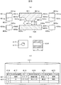
- a search is performed based on the feature shape. For example, if the feature is a gap, the distance between the faces is calculated, and a gap search is executed by comparing with the gap distance determination condition registered in the analytical modeling technique database 112 (step S307). For example, when two components shown in FIG. 5A, component 1 (401) and component 2 (406) are arranged close to each other, ten surfaces 401a to 401k constituting component 1 (401), A unique number assigned to each of the six surfaces 406a to 406f constituting the component 2 (406) (referred to as a surface ID) is searched (step S308). Next, based on the surface ID, distances (center distances between the surfaces) d between the surfaces 401a to 401k and the surfaces 406a to 406f are obtained (step S309).
- the surface IDs constituting the component 1 (401) are sequentially traced from the surface 1 (401a), and the surface IDs 401a to 401 For 401k, the distance d to the surfaces 406a to 406f of the counterpart part 2 and the normal vector for the counterpart part 2 are obtained. That is, in the central view of FIG. 5A, which is a cross-sectional view of the component 1 (401) and the component 2 (406), the normal vector of the surface 401e of the component 1 (401) and the surface 406a of the component 2 (406). 409 and 410 are obtained.
- the distance d between the surface 401e and the surface 406a is calculated. If the distance between the surface 401e and the surface 406a is equal to or smaller than the threshold of the determination condition, or the angle formed by the two normal vectors 409 and 410 is close to 180 degrees, this portion is determined as a gap.
- the calculated value of the center distance between each surface is compared with the determination condition of the analytical modeling technique database 112. That is, it is compared whether or not the distance d between the surfaces is 0.5 mm or more.
- the distance between the centers of the surfaces is 0.5 mm or more, it is determined whether or not to make an inquiry as a “gap” based on the determination condition.
- “gap” information is registered and stored in the CAD feature shape database 111 (step S310).
- a highlighted portion is set (step S311).
- the CAD feature shape database 111 stores the feature shapes included in the CAD data in a tabular format.
- a number column 416, a shape feature type column 417, a parameter column 418, a shape feature name column 419, a model shape 420 column, an analysis modeling column 423, etc. are provided on the horizontal axis of the table. ing.
- These item columns 416 to 422 and 423 store characteristic shape parameters.
- the feature is a gap
- “gap”, “d 0.02” as the gap distance
- “fastening distance” as the gap distance
- part 1, part 2” as the component information
- a hole search is executed (step S312).
- the search is performed in comparison with the determination condition of the modeling method based on the line information that forms the circular arc that is the cylindrical surface that forms the hole or the peripheral edge of the hole. For example, when a through hole 413 having a radius r and a depth h is formed in the component 3 (412) as shown in FIG. 5B, the six side surfaces and one component constituting the component 3 (412) are formed.
- the surface ID is searched for the cylindrical surface 414 (step S313). And it is determined whether those surfaces are cylindrical surfaces.
- the radius 314 is extracted as r from the line information constituting the cylindrical surface 414 (step S314), and the depth 315 is extracted as h (step S315). Further, the inquiry content is determined by comparison with the determination condition of the modeling method. For example, it is examined whether or not the condition that the radius r is r ⁇ 5 and the depth h is h ⁇ 7 is satisfied. When both the radius and the depth satisfy this condition, it is further determined whether or not to execute the inquiry based on the above determination condition as a hole. When inquiring as a hole, the gap information is registered and stored in the CAD feature shape database 111 (step S316). At the same time, a highlighted portion is set (step S317).
- the hole information is stored as the shape feature in the data 422 in the second row.
- the shape feature type column 417 has “hole”
- the parameter 418 column has radius r and depth h
- the shape feature name column 419 has “bolt hole”.
- “part 3” is stored in the model shape column 420 as the component information.
- the analysis modeling column 423 information related to modeling of “deleting” a hole is stored and can be used when an analysis model is created.
- step S318 The content of the answer to the inquired item after executing the above search is highlighted on the operation screen of the input / output device 100 (step S318).
- model conversion from the three-dimensional CAD model to the analysis CAD model becomes possible, and model conversion is performed (step S319).
- step S320 the inquiry result is also highlighted on the operation screen of the analysis CAD model in the same manner as on the three-dimensional CAD model screen (step S320).
- the intention of the designer is reflected in the analysis CAD model and handed over to the screen of the analysis specialist.
- information on analysis modeling is stored as modeling contents after inquiring how to perform analysis modeling.
- a table stored in the CAD feature shape database 111 may be stored in connection with CAD data and referred to when creating an analysis model.
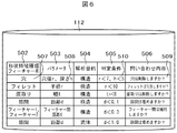
- FIG. 6 is a diagram illustrating an example of the contents of the analysis modeling technique database 112.
- the analysis modeling technique database 112 stores determination conditions for interactively inquiring to an analysis specialist how to model a feature shape when creating an analysis model.
- a shape feature type / feature name column 502 On the horizontal axis of the table stored in the analysis modeling technique database 112, a shape feature type / feature name column 502, a parameter column 503, an analysis purpose column 504, a determination condition column 505, and an inquiry content column 506 are provided. .
- the model information delivery device 160 checks.
- the CAD feature shape database 111 is used to register each feature shape extracted from the CAD data or the three-dimensional CAD model in the analysis modeling technique database 112 in the order described in the number column 416 of the CAD feature shape database 111. Trace whether the method is satisfied. If the determination condition is satisfied, the inquiry information is displayed on the operation screen of the input / output device 100.
- the hole diameter r and the depth h are equal to or less than the determination condition 510, that is, r ⁇ 7 mm, h If it is ⁇ 5 mm, “Do you want to delete the hole?” Described in the inquiry content column 509 is displayed on the operation screen of the input / output device 100 in order to make an interactive inquiry to the analysis specialist.
- information on the hole is registered in the number column of the second row of the CAD feature shape database 111 with “2”, the hole diameter is 5 mm, and the height is 2 mm.
- the determination condition 510 of the modeling method regarding the hole is satisfied, and a message 509 “Do you want to delete the hole?” Is displayed on the operation screen.
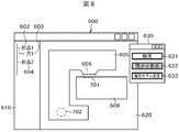
- FIG. 7 is a display example of the first operation screen 600.
- the first operation screen 600 includes a shape display field 620 on the right side on which a three-dimensional CAD drawing and an analysis CAD drawing are displayed, and a component that indicates constituent members and features included in the analysis target component that is the basis of the three-dimensional CAD drawing. And a name and feature column 610.
- the first operation screen 600 is an operation screen for searching for a shape or feature name that is a feature from the information of the feature shape and the feature name with respect to the three-dimensional CAD data.
- the part name and feature column 610 the part 1 (602), the hole 1 (603) which is the feature name of the part 1, and the part 2 (604) constituting the three-dimensional CAD screen 620 are displayed in a tree diagram. Yes.
- the shape display column 620 a diagram for three-dimensional CAD of the part 1 (605) and the part 2 (608) is displayed.
- the part 1 (605) is a U-shaped two-dimensional member
- the part 2 (608) is a rectangular parallelepiped part.
- the component 1 (605) has a protrusion-shaped portion 606 and a hole-shaped portion 607. Further, the relative positions of the component 1 (605) and the component 2 (608) are displayed in the same manner as the actual arrangement.
- an operation menu screen 630 is displayed.
- the operation menu screen 630 includes a search button 631, an inquiry display button 632, and an analysis model conversion button 633.
- the search button 631 is highlighted (state in FIG. 7).
- the analysis model information delivery device 160 selects a feature shape from the feature shape and feature name information in accordance with step S204 described above, and uses the information stored in the CAD feature shape database 111 as the rules of the analysis modeling technique database 112. While comparing, the features of the CAD data or the three-dimensional CAD model are extracted. The extracted result is highlighted. Since the processing in step S205 has been completed, the designer who is the user clicks the inquiry display button 632 on the operation menu screen 630 on the first operation screen 600. This state is shown in FIG. As shown in FIG. 8, the inquiry display button 632 is highlighted.
- the hole 702 is determined from the hole shape portion which is the shape feature of the part 1 (605) or from the hole 1 (603) which is the information of the feature name of the part 1 (605), and is highlighted in the same manner as the gap 701. .
- the analysis model information delivery device 160 Since the inquiry display button 632 has been pressed, the analysis model information delivery device 160 has an inquiry written on the first operation screen 600 of the input / output device 100 as “Do you want to fill the gap?” Instead of the operation menu screen 630.
- a screen 800 is displayed.
- the inquiry screen 800 is provided with a Yes button 802 and a No button 803 for user response.
- the state of the first operation screen 600 before the user response is shown in FIG.
- the inquiry screen 800 in which “Do you want to fill the gap?” Is displayed for the portion determined as a gap in step S205. That is, on the inquiry screen 800, the question changes according to the inquiry content.
- the inquiry content is created when the information registered in the CAD feature shape database 111 and the analysis modeling technique database 112 are searched in step S204.
- FIG. 10 and 11 show an example in which the mouse pointer 820 is displayed on the first operation screen 800 in order to clearly indicate the feature points in the CAD data.
- FIG. 10 is a diagram corresponding to FIG. 8.
- FIG. 8 shows the state after the inquiry display button 632 is clicked, but the inquiry button 632 is not yet clicked in FIG. Everything else is the same.
- FIG. 11 is a diagram corresponding to FIG. 9 and is the same except for the mouse pointer 820. By moving the mouse pointer 820 to the highlighted location, the user can interactively select the inquiry location.
- FIG. 12 shows a first operation screen 600 when the analysis model information delivery device 160 inquires about the processing of the hole 702 that is a feature point formed in the part 1 (605). Although the wording on the inquiry screen 810 has changed to “Do you want to delete the hole?”, The rest is the same as in the case of the gap 701.
- This inquiry screen 810 is also provided with a Yes button 812 and a No button 813 for user response.
- An operation menu screen 630 is also displayed on the first operation screen 600.
- the designer who is the user clicks the Yes button 812 with respect to the inquiry content information on the analysis modeling method is added, and when the designer clicks the No button 813, it is determined that the hole is reproduced in the analysis model. The determined part is highlighted.
- FIG. 13 shows an example of the first operation screen 600 when converting to an analysis model now.
- the designer presses the analysis model conversion button 633 on the operation menu screen 630 the designer moves from the three-dimensional CAD screen to the second operation screen 900 on which the analysis software shown in FIG. 14 is activated.
- the shape of the 3D CAD model in which information interactively responding to the inquiry content from the analysis model information delivery device 160 is embedded is displayed on the second operation screen 900 as the outline of the analysis model. Is displayed. This response information is stored in the CAD feature shape database 111.
- step S207 a response is received by clicking the Yes button 802 in response to the inquiry “Do you want to fill the gap?”
- the gap between the member 1 (905) and the member 2 (908). 911 is filled.
- the hole 912 responds by clicking the Yes button 812 to the inquiry “Do you want to delete the hole?”
- the hole is deleted on the second operation screen 900. At this time, both target portions are highlighted.
- step S207 a response is received by clicking the No button 813 in response to the inquiry “Do you want to fill the gap?”, And a response in response to the inquiry “Delete the hole?” By clicking the Yes button 812.
- An example of the second operation screen 900 is shown in FIG. On the second operation screen 900, a gap 911a is reproduced between the member 1 (905) and the member 2 (908). Further, the hole 912a is deleted. At this time, both target portions are highlighted.
- FIG. 17 is an example of an operation screen when a mesh is created by analysis software. Information that the designer responds interactively using CAD software is inherited even after the mesh is created, and the analysis modeling method can be confirmed.
- the NO button 812 responds to the inquiry content “Do you want to fill the gap?”, The gap is filled at the time of mesh generation. If the modeling method and the mesh generation result are different due to such an erroneous operation, the wrong part is highlighted.
- an analytical CAD model is created from a three-dimensional CAD model by applying an analytical modeling method to the gap and hole shape.
- creation of a data embedding analysis CAD model specific to the model to be analyzed is supported. Therefore, it is possible to reduce the occurrence of reconfirmation of the modeling method from the analysis specialist to the designer, and the failure and rework of the analysis work.
- the data can be centrally managed, it is easier to manage and eliminate omissions and mistakes in production instructions compared to the conventional case where information on gaps and hole shapes is indicated on paper drawings. Can be prevented.
- a part where an analytical modeling method is input is searched using shape search or name search to support creation of an analytical CAD model.
- support for modeling similar parts using the know-how of past analysis results, or search for similar parts using material names used in past analysis result models, and support modeling are effective if the analysis target is similar to the past analysis, but when analyzing shapes that have not been experienced in the past, If they are different, there are fewer cases where adaptation is possible.
- the creation support of the analysis CAD model is dominated by the past analysis target. It will never be done.
- the analysis modeling method according to the analysis purpose can be applied, it is an effective method for reducing failure and rework in the analysis work.
- the determination location is displayed more emphasized than when the entire surface that satisfies the determination condition is highlighted.
- it is possible to prevent oversight such as addition to an extra part or a case where parts satisfying the judgment condition are adjacent to each other.
- the method of displaying the minimum range when there are two surfaces A, B and two surfaces having a short distance between the surfaces, the surface having the smaller area, for example, the B surface is highlighted to display the minimum range. .
- holes and gaps have been described as examples.
- the features targeted by the present invention are not limited to holes and gaps, but include all processes necessary for processing and production of products such as fillets and chamfers.
Landscapes
- Physics & Mathematics (AREA)
- Engineering & Computer Science (AREA)
- Geometry (AREA)
- Theoretical Computer Science (AREA)
- General Physics & Mathematics (AREA)
- Pure & Applied Mathematics (AREA)
- Mathematical Optimization (AREA)
- Mathematical Analysis (AREA)
- Computer Hardware Design (AREA)
- Evolutionary Computation (AREA)
- General Engineering & Computer Science (AREA)
- Computational Mathematics (AREA)
- Computer Graphics (AREA)
- Software Systems (AREA)
- Management, Administration, Business Operations System, And Electronic Commerce (AREA)
Abstract
Priority Applications (3)
| Application Number | Priority Date | Filing Date | Title |
|---|---|---|---|
| PCT/JP2011/053846 WO2012114457A1 (fr) | 2011-02-22 | 2011-02-22 | Dispositif d'émission d'informations de modèles analytiques et programme d'émission d'informations de modèles analytiques |
| JP2013500753A JP5760076B2 (ja) | 2011-02-22 | 2011-02-22 | 解析モデル情報引き渡し装置及び解析モデル情報引き渡しプログラム |
| US13/983,425 US20130321415A1 (en) | 2011-02-22 | 2011-02-22 | Analytical Model Information Delivery Device and Analytical Model Information Delivery Program |
Applications Claiming Priority (1)
| Application Number | Priority Date | Filing Date | Title |
|---|---|---|---|
| PCT/JP2011/053846 WO2012114457A1 (fr) | 2011-02-22 | 2011-02-22 | Dispositif d'émission d'informations de modèles analytiques et programme d'émission d'informations de modèles analytiques |
Publications (1)
| Publication Number | Publication Date |
|---|---|
| WO2012114457A1 true WO2012114457A1 (fr) | 2012-08-30 |
Family
ID=46720277
Family Applications (1)
| Application Number | Title | Priority Date | Filing Date |
|---|---|---|---|
| PCT/JP2011/053846 Ceased WO2012114457A1 (fr) | 2011-02-22 | 2011-02-22 | Dispositif d'émission d'informations de modèles analytiques et programme d'émission d'informations de modèles analytiques |
Country Status (3)
| Country | Link |
|---|---|
| US (1) | US20130321415A1 (fr) |
| JP (1) | JP5760076B2 (fr) |
| WO (1) | WO2012114457A1 (fr) |
Cited By (3)
| Publication number | Priority date | Publication date | Assignee | Title |
|---|---|---|---|---|
| JP2015158752A (ja) * | 2014-02-21 | 2015-09-03 | 公立大学法人首都大学東京 | 3次元cadモデル類似検索方法 |
| US9898826B2 (en) | 2015-03-31 | 2018-02-20 | Canon Kabushiki Kaisha | Information processing apparatus, information processing method, and program |
| WO2020121637A1 (fr) * | 2018-12-14 | 2020-06-18 | 株式会社日立製作所 | Dispositif de simulation, programme de simulation et procédé de simulation |
Families Citing this family (7)
| Publication number | Priority date | Publication date | Assignee | Title |
|---|---|---|---|---|
| US10061870B2 (en) | 2014-03-18 | 2018-08-28 | Palo Alto Research Center Incorporated | Automated metrology and model correction for three dimensional (3D) printability |
| CN107076684B (zh) | 2014-09-02 | 2021-04-02 | 株式会社尼康 | 测量处理装置、测量处理方法和测量处理程序 |
| JP6763301B2 (ja) * | 2014-09-02 | 2020-09-30 | 株式会社ニコン | 検査装置、検査方法、検査処理プログラムおよび構造物の製造方法 |
| US11886776B2 (en) * | 2018-05-08 | 2024-01-30 | Autodesk, Inc. | Techniques for generating graph-based representations of complex mechanical assemblies |
| EP3767414A1 (fr) * | 2019-07-17 | 2021-01-20 | Borges3D B.V. | Système de commande à utiliser dans un système de fabrication d'objet tridimensionnel et procédé de fonctionnement correspondant |
| JP7286508B2 (ja) * | 2019-10-11 | 2023-06-05 | 株式会社日立製作所 | 設計支援装置、設計支援方法、および設計支援プログラム |
| CN113656520B (zh) * | 2021-08-10 | 2022-10-28 | 广州市规划和自然资源自动化中心(广州市基础地理信息中心) | 空间分析方法、装置、计算机设备和存储介质 |
Citations (3)
| Publication number | Priority date | Publication date | Assignee | Title |
|---|---|---|---|---|
| JP2000331194A (ja) * | 1999-05-24 | 2000-11-30 | Hitachi Ltd | 形状モデル簡略化方法 |
| JP2002318891A (ja) * | 2001-04-24 | 2002-10-31 | Toshiba Microelectronics Corp | 製品開発マネジメントシステム、製品開発マネジメント方法、製品信頼性判定システム及び製品信頼性判定方法 |
| JP2003337836A (ja) * | 2002-05-21 | 2003-11-28 | Hitachi Ltd | 解析用モデル作成方法および解析用モデル作成装置 |
Family Cites Families (4)
| Publication number | Priority date | Publication date | Assignee | Title |
|---|---|---|---|---|
| JP3800916B2 (ja) * | 2000-03-17 | 2006-07-26 | 株式会社日立製作所 | 解析モデル生成装置、解析モデル生成プログラムを記憶した記憶媒体及び記憶装置 |
| EP1152428A3 (fr) * | 2000-04-28 | 2004-01-02 | SmarkDisk Corporation | Collecteur digital de donnée amélioré |
| US6828963B1 (en) * | 2000-09-06 | 2004-12-07 | Proficiency Ltd. | Pattern matching for data exchange between computer aided design systems |
| JP4588502B2 (ja) * | 2005-03-17 | 2010-12-01 | 富士通株式会社 | プリント配線基板設計支援装置、プリント配線基板設計支援方法、及びプリント配線基板設計支援プログラム |
-
2011
- 2011-02-22 WO PCT/JP2011/053846 patent/WO2012114457A1/fr not_active Ceased
- 2011-02-22 JP JP2013500753A patent/JP5760076B2/ja not_active Expired - Fee Related
- 2011-02-22 US US13/983,425 patent/US20130321415A1/en not_active Abandoned
Patent Citations (3)
| Publication number | Priority date | Publication date | Assignee | Title |
|---|---|---|---|---|
| JP2000331194A (ja) * | 1999-05-24 | 2000-11-30 | Hitachi Ltd | 形状モデル簡略化方法 |
| JP2002318891A (ja) * | 2001-04-24 | 2002-10-31 | Toshiba Microelectronics Corp | 製品開発マネジメントシステム、製品開発マネジメント方法、製品信頼性判定システム及び製品信頼性判定方法 |
| JP2003337836A (ja) * | 2002-05-21 | 2003-11-28 | Hitachi Ltd | 解析用モデル作成方法および解析用モデル作成装置 |
Cited By (3)
| Publication number | Priority date | Publication date | Assignee | Title |
|---|---|---|---|---|
| JP2015158752A (ja) * | 2014-02-21 | 2015-09-03 | 公立大学法人首都大学東京 | 3次元cadモデル類似検索方法 |
| US9898826B2 (en) | 2015-03-31 | 2018-02-20 | Canon Kabushiki Kaisha | Information processing apparatus, information processing method, and program |
| WO2020121637A1 (fr) * | 2018-12-14 | 2020-06-18 | 株式会社日立製作所 | Dispositif de simulation, programme de simulation et procédé de simulation |
Also Published As
| Publication number | Publication date |
|---|---|
| JPWO2012114457A1 (ja) | 2014-07-07 |
| US20130321415A1 (en) | 2013-12-05 |
| JP5760076B2 (ja) | 2015-08-05 |
Similar Documents
| Publication | Publication Date | Title |
|---|---|---|
| JP5760076B2 (ja) | 解析モデル情報引き渡し装置及び解析モデル情報引き渡しプログラム | |
| KR101746477B1 (ko) | 개체에 대한 스타일 동시 편집을 지원하는 문서 협업 장치 및 그 동작 방법 | |
| JP6452882B1 (ja) | ウェブブラウザの操作を伴う業務プロセスを自動化するためのシステム、方法及びプログラム | |
| JP4479802B2 (ja) | 受注管理装置、その受注管理方法、コンピュータプログラム | |
| JP2017091208A (ja) | 文書点検支援装置、文書点検支援システム及びプログラム | |
| US8874414B2 (en) | Model population | |
| JP5179607B2 (ja) | 会計管理システム、会計管理方法及び会計管理プログラム | |
| CN114072787A (zh) | 用于促进文档审核的快速数据输入的系统和方法 | |
| KR102425638B1 (ko) | 설계지원 시스템 | |
| WO2014122763A1 (fr) | Dispositif de traitement de données cad et procédé de traitement | |
| AU2021106041A4 (en) | Methods and systems for obtaining and storing web pages | |
| JP6571428B2 (ja) | シールドトンネル作図装置 | |
| JP6097231B2 (ja) | プログラム生成装置および方法 | |
| JP2020184267A (ja) | 3次元cad装置、及び3次元cadプログラム | |
| KR102335433B1 (ko) | 입체의 3d 도면을 기반으로하여 자동으로 전개도를 생성하는 전개도 생성 시스템 | |
| KR102401345B1 (ko) | 사용자 계정 정보에 기반한 복수 작성자의 컨텐츠 작성 방법 및 그 장치 | |
| KR101452296B1 (ko) | 조선해양분야 3차원 모델링의 강재마진 선모델링 반영 최적화 방법 | |
| KR102528779B1 (ko) | 한국어 생략어 복원을 위한 학습 말뭉치 생성 장치 및 방법 | |
| JP2016014979A (ja) | パラメータ設定支援システム、パラメータ設定支援方法およびパラメータ設定支援プログラム | |
| CN121544014B (zh) | 高频报工场景下的自动化报工方法及装置 | |
| CN112257450A (zh) | 数据处理方法、装置、可读存储介质及设备 | |
| JP2020204963A (ja) | ワークフローシステム、情報処理装置、情報処理方法及びプログラム | |
| JP4867229B2 (ja) | 情報処理装置及びプログラム | |
| JP6665637B2 (ja) | プログラム作成支援システム | |
| JP5279149B2 (ja) | Cadデータ作成装置、cadデータ作成方法及びコンピュータプログラム |
Legal Events
| Date | Code | Title | Description |
|---|---|---|---|
| 121 | Ep: the epo has been informed by wipo that ep was designated in this application |
Ref document number: 11859260 Country of ref document: EP Kind code of ref document: A1 |
|
| ENP | Entry into the national phase |
Ref document number: 2013500753 Country of ref document: JP Kind code of ref document: A |
|
| WWE | Wipo information: entry into national phase |
Ref document number: 13983425 Country of ref document: US |
|
| NENP | Non-entry into the national phase |
Ref country code: DE |
|
| 122 | Ep: pct application non-entry in european phase |
Ref document number: 11859260 Country of ref document: EP Kind code of ref document: A1 |