WO2012114540A1 - 圧力容器 - Google Patents
圧力容器 Download PDFInfo
- Publication number
- WO2012114540A1 WO2012114540A1 PCT/JP2011/060670 JP2011060670W WO2012114540A1 WO 2012114540 A1 WO2012114540 A1 WO 2012114540A1 JP 2011060670 W JP2011060670 W JP 2011060670W WO 2012114540 A1 WO2012114540 A1 WO 2012114540A1
- Authority
- WO
- WIPO (PCT)
- Prior art keywords
- welded
- welding
- shape
- plate
- weld
- Prior art date
- Legal status (The legal status is an assumption and is not a legal conclusion. Google has not performed a legal analysis and makes no representation as to the accuracy of the status listed.)
- Ceased
Links
Images


Classifications
-
- B—PERFORMING OPERATIONS; TRANSPORTING
- B29—WORKING OF PLASTICS; WORKING OF SUBSTANCES IN A PLASTIC STATE IN GENERAL
- B29D—PRODUCING PARTICULAR ARTICLES FROM PLASTICS OR FROM SUBSTANCES IN A PLASTIC STATE
- B29D30/00—Producing pneumatic or solid tyres or parts thereof
- B29D30/06—Pneumatic tyres or parts thereof (e.g. produced by casting, moulding, compression moulding, injection moulding, centrifugal casting)
- B29D30/0601—Vulcanising tyres; Vulcanising presses for tyres
-
- F—MECHANICAL ENGINEERING; LIGHTING; HEATING; WEAPONS; BLASTING
- F16—ENGINEERING ELEMENTS AND UNITS; GENERAL MEASURES FOR PRODUCING AND MAINTAINING EFFECTIVE FUNCTIONING OF MACHINES OR INSTALLATIONS; THERMAL INSULATION IN GENERAL
- F16J—PISTONS; CYLINDERS; SEALINGS
- F16J12/00—Pressure vessels in general
-
- B—PERFORMING OPERATIONS; TRANSPORTING
- B23—MACHINE TOOLS; METAL-WORKING NOT OTHERWISE PROVIDED FOR
- B23K—SOLDERING OR UNSOLDERING; WELDING; CLADDING OR PLATING BY SOLDERING OR WELDING; CUTTING BY APPLYING HEAT LOCALLY, e.g. FLAME CUTTING; WORKING BY LASER BEAM
- B23K31/00—Processes relevant to this subclass, specially adapted for particular articles or purposes, but not covered by any single one of main groups B23K1/00 - B23K28/00
-
- B—PERFORMING OPERATIONS; TRANSPORTING
- B23—MACHINE TOOLS; METAL-WORKING NOT OTHERWISE PROVIDED FOR
- B23K—SOLDERING OR UNSOLDERING; WELDING; CLADDING OR PLATING BY SOLDERING OR WELDING; CUTTING BY APPLYING HEAT LOCALLY, e.g. FLAME CUTTING; WORKING BY LASER BEAM
- B23K31/00—Processes relevant to this subclass, specially adapted for particular articles or purposes, but not covered by any single one of main groups B23K1/00 - B23K28/00
- B23K31/003—Processes relevant to this subclass, specially adapted for particular articles or purposes, but not covered by any single one of main groups B23K1/00 - B23K28/00 relating to controlling of welding distortion
-
- B—PERFORMING OPERATIONS; TRANSPORTING
- B23—MACHINE TOOLS; METAL-WORKING NOT OTHERWISE PROVIDED FOR
- B23K—SOLDERING OR UNSOLDERING; WELDING; CLADDING OR PLATING BY SOLDERING OR WELDING; CUTTING BY APPLYING HEAT LOCALLY, e.g. FLAME CUTTING; WORKING BY LASER BEAM
- B23K31/00—Processes relevant to this subclass, specially adapted for particular articles or purposes, but not covered by any single one of main groups B23K1/00 - B23K28/00
- B23K31/12—Processes relevant to this subclass, specially adapted for particular articles or purposes, but not covered by any single one of main groups B23K1/00 - B23K28/00 relating to investigating the properties, e.g. the weldability, of materials
- B23K31/125—Weld quality monitoring
-
- B—PERFORMING OPERATIONS; TRANSPORTING
- B23—MACHINE TOOLS; METAL-WORKING NOT OTHERWISE PROVIDED FOR
- B23K—SOLDERING OR UNSOLDERING; WELDING; CLADDING OR PLATING BY SOLDERING OR WELDING; CUTTING BY APPLYING HEAT LOCALLY, e.g. FLAME CUTTING; WORKING BY LASER BEAM
- B23K33/00—Specially-profiled edge portions of workpieces for making soldering or welding connections; Filling the seams formed thereby
- B23K33/004—Filling of continuous seams
- B23K33/006—Filling of continuous seams for cylindrical workpieces
-
- B—PERFORMING OPERATIONS; TRANSPORTING
- B23—MACHINE TOOLS; METAL-WORKING NOT OTHERWISE PROVIDED FOR
- B23K—SOLDERING OR UNSOLDERING; WELDING; CLADDING OR PLATING BY SOLDERING OR WELDING; CUTTING BY APPLYING HEAT LOCALLY, e.g. FLAME CUTTING; WORKING BY LASER BEAM
- B23K9/00—Arc welding or cutting
-
- B—PERFORMING OPERATIONS; TRANSPORTING
- B29—WORKING OF PLASTICS; WORKING OF SUBSTANCES IN A PLASTIC STATE IN GENERAL
- B29C—SHAPING OR JOINING OF PLASTICS; SHAPING OF MATERIAL IN A PLASTIC STATE, NOT OTHERWISE PROVIDED FOR; AFTER-TREATMENT OF THE SHAPED PRODUCTS, e.g. REPAIRING
- B29C33/00—Moulds or cores; Details thereof or accessories therefor
- B29C33/02—Moulds or cores; Details thereof or accessories therefor with incorporated heating or cooling means
- B29C33/04—Moulds or cores; Details thereof or accessories therefor with incorporated heating or cooling means using liquids, gas or steam
-
- B—PERFORMING OPERATIONS; TRANSPORTING
- B29—WORKING OF PLASTICS; WORKING OF SUBSTANCES IN A PLASTIC STATE IN GENERAL
- B29C—SHAPING OR JOINING OF PLASTICS; SHAPING OF MATERIAL IN A PLASTIC STATE, NOT OTHERWISE PROVIDED FOR; AFTER-TREATMENT OF THE SHAPED PRODUCTS, e.g. REPAIRING
- B29C35/00—Heating, cooling or curing, e.g. crosslinking or vulcanising; Apparatus therefor
- B29C35/02—Heating or curing, e.g. crosslinking or vulcanizing during moulding, e.g. in a mould
- B29C35/0227—Heating or curing, e.g. crosslinking or vulcanizing during moulding, e.g. in a mould using pressure vessels, e.g. autoclaves, vulcanising pans
-
- B—PERFORMING OPERATIONS; TRANSPORTING
- B29—WORKING OF PLASTICS; WORKING OF SUBSTANCES IN A PLASTIC STATE IN GENERAL
- B29D—PRODUCING PARTICULAR ARTICLES FROM PLASTICS OR FROM SUBSTANCES IN A PLASTIC STATE
- B29D30/00—Producing pneumatic or solid tyres or parts thereof
- B29D30/06—Pneumatic tyres or parts thereof (e.g. produced by casting, moulding, compression moulding, injection moulding, centrifugal casting)
- B29D30/0601—Vulcanising tyres; Vulcanising presses for tyres
- B29D30/065—Tyre-vulcanising presses with two or more moulds, e.g. stacked upon each other
-
- B—PERFORMING OPERATIONS; TRANSPORTING
- B23—MACHINE TOOLS; METAL-WORKING NOT OTHERWISE PROVIDED FOR
- B23K—SOLDERING OR UNSOLDERING; WELDING; CLADDING OR PLATING BY SOLDERING OR WELDING; CUTTING BY APPLYING HEAT LOCALLY, e.g. FLAME CUTTING; WORKING BY LASER BEAM
- B23K2101/00—Articles made by soldering, welding or cutting
- B23K2101/04—Tubular or hollow articles
- B23K2101/12—Vessels
Definitions
- the present invention relates to a pressure vessel used in, for example, a tire manufacturing apparatus, and more particularly to a plate material welded portion structure such as a top plate or a bottom plate that is welded to a body plate or an end plate in the vessel.
- pressure vessels that receive a pressure higher than atmospheric pressure are widely used inside the vessel in which end plates are welded to the top and bottom of the body plate.
- a pressure vessel has a structure in which an end portion of a plate material is attached by welding to a wall member of a body plate or an end plate, such as a top plate that is attached so as to partition the inside of the container body and receives pressure.
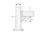
- FIG. 9 is a cross-sectional view showing a conventional structure of a welded structure portion for attaching a top plate to a wall surface member of a pressure vessel by welding.
- the end portion of the plate member 1 is welded by the welded portion 3 so as to have a substantially T-shaped cross section with respect to the wall surface member 2.
- Such a welded portion 3 is machined so as to be an exposed surface 4 that forms a tapered shape, an R shape, or the like in order to relieve stress concentration in the welded portion.
- machining the welded portion 3 described above into an R shape is disclosed in, for example, Patent Document 1 below.
- the exposed surface 4 extended by increasing the tapered surface of the welded portion or increasing the radius of the R shape is effective.
- the amount of heat input by welding also increases as a result.
- the heat input of welding is limited by the plate thickness t of the wall member 2 to be welded to the plate 1. For this reason, when it is going to relieve stress concentration by the taper surface or R shape mentioned above, the problem that the plate
- the present invention has been made in view of the above circumstances, and the object thereof is to have a welded portion structure of a plate material that attaches a plate material that receives pressure or load to a wall surface member such as a body plate or an end plate by welding.
- An object of the present invention is to provide a pressure vessel that relaxes stress concentration by reducing or suppressing an increase in welding amount and wall member plate thickness.
- the pressure vessel according to the present invention is a pressure vessel having a welded structure in which an end of a member that is attached so as to partition the inside of the vessel main body and receives pressure and load is attached by welding to a wall member of the vessel main body.
- at least two shape displacement points including the welded portion are provided in the welded structure portion.
- a suitable shape displacement point in this case is to provide a stepped portion formed in, for example, a taper shape or an R shape on the wall surface member.
- Such a pressure vessel of the present invention is desirably used for a tire manufacturing apparatus for vulcanizing a tire inside the vessel, for example.
- the stress concentration portion is dispersed at a plurality of locations by providing at least two shape displacement points including the weld portion in the weld structure portion, the stress peak value acting on the weld structure portion of the pressure vessel And the mechanical life of the pressure vessel can be improved. That is, the welded structure portion can avoid stress concentration relaxation of the welded portion due to the extension of the taper shape, R shape, etc., which increases the welding amount of the welded portion, so that the welding cost and welding distortion can be reduced. Further, since the body plate and the end plate as the wall member do not increase the welding amount, there is no increase in the plate thickness due to the restriction of the heat input amount, and the material cost, can manufacturing cost and transportation cost can be reduced.
- FIG. 1 shows an embodiment of a pressure vessel according to the present invention, and is a cross-sectional view showing a weld structure portion in a final state in which a top plate is attached to a wall surface member of the pressure vessel by welding to provide a stepped portion.
- 1 shows an embodiment of a pressure vessel according to the present invention, and is a cross-sectional view showing a welded structure in a state after welding and before machining. It is a graph of the stress ratio compared with the conventional structure of FIG. 9 about the stress peak value of the welded structure shown in FIG. 1A. It is sectional drawing which shows the structural example of a tire manufacturing apparatus as an application example of the pressure vessel which concerns on this invention.
- FIG. 10 a structural example of a tire manufacturing apparatus (tire vulcanizer) is shown in FIG.
- the illustrated tire manufacturing apparatus 10 is an apparatus called an autoclave (or a hot heater) used for vulcanization of tires for large vehicles such as construction machines.
- the tire manufacturing apparatus 10 is a pressure vessel manufactured based on the first type pressure vessel structure standard in Japan.
- the pressure vessel used for vulcanizing the tire is detachably connected to the upper dome 11 and the lower dome 12 via a connecting ring 13 so as to block outside air, and the fluid pressure in the cylinder 14 is reduced.
- a load (pressing force) due to (air, water pressure, hydraulic pressure, etc.) and a load due to the steam pressure in the lower dome 12 are supported.
- the mold 16 containing the green tire 15 to be vulcanized is stacked on the mold table 17 in three to four stages.
- reference numeral 18 denotes a ram that transmits the pressing force
- 19 denotes a flexible hose that supplies hot water and cooling water to the green tire
- 20 and 21 denote green hot water and cooling water supplied via the flexible hose 19. It is a nozzle that sprays and cools the tire 15.
- the above-mentioned upper dome 11 is formed by welding an end plate to an upper part of a cylindrical body plate.
- a plate-like top plate 22 is attached to the upper dome 11 so as to partition the inside of the pressure vessel configured with the lower dome 12 and the connecting ring 13 vertically.
- the top plate 22 is attached by welding so that the end portion of the plate material has a substantially T-shaped cross section with respect to the wall surface member 30 that forms the cylindrical upper portion of the container body.
- a welded portion where the top plate 22 is welded to the wall surface member 30 is referred to as a welded portion 40.
- the wall surface member 30 in this case is a cylindrical body plate constituting the upper dome 11 or a cylindrical portion of an end plate welded to the body plate.
- the pressure vessel of this embodiment is attached so that the inside of a container main body may be partitioned, and the edge part of the top plate 22 which receives a pressure and a load is attached to the wall surface member 30 of the container main body by the welding part 40 illustration.
- at least two shape displacement points including the welded portion 40 are provided in the welded structure portion.
- a stepped portion 50 is provided as a shape displacement point.
- the stepped portion 50 is a tapered surface generated by reducing (thinning) the plate thickness t of the wall surface member 30 by a thickness d by machining or the like.
- FIG. 1A shows a final shape after machining, in which machining is performed from the welded portion 40 ′ in the state after welding shown in FIG. 1B. That is, the welded portion 40 ′ after welding has a weld leg length of W, and is subjected to machining from this state to become a final-shaped welded portion 40. Further, a plate thickness t is thickened by machining below the welded portion 40.
- a step portion 50 is formed at the plate thickness displacement point that is thinned by a distance d.
- the welding part 40 of this embodiment is machined so that the exposed surface 42 may form a taper surface.
- the step portion 50 has a shape change starting point at which the distance from the lower surface of the top plate 22 to the weld toe 41 is L 0 and the step portion 50 is started from the weld toe 41.
- the distance to 51 and L 1 and are provided cutting length from the shape change start point 51 to the shape change end point 52 a (tapered growth) to the L 2.
- L 0 , L 1 , L 2 and d are 0 ⁇ L 0 ⁇ W, 0 ⁇ L 1 ⁇ 5 L 0 , 0, where W is the weld leg length after welding, that is, the weld leg length before machining.
- the weld leg length W shown in FIG. 1B is equal to or greater than L 0 of the distance from the lower surface of the top plate 22 to the weld toe 41 (W ⁇ L 0 ).
- the welded structure portion of the present embodiment in which the top plate 22 is welded to the wall surface member 30 is provided with two shape displacement points such as the welded portion 40 and the stepped portion 50.
- the stress concentration value can be reduced by dispersing the stress concentration position at two locations. That is, since the shape displacement points of the welded structure portion are provided at two locations of the welded portion 40 and the stepped portion 50, the rigidity of the welded structure portion is lowered and the stress peak value is also lowered.
- FIG. 2 shows a comparison of calculated stress peak values for the structure of the present application shown in FIG. 1A and the conventional structure shown in FIG. That is, in the welded structure portion having the above-described structure, if the stress peak value ⁇ u of the conventional structure is set to 1, the stress peak value ⁇ of the structure of the present invention provided with the stepped portion 50 is reduced to 1 or less. . As a result, the pressure vessel having the welded structure according to the present embodiment has excellent durability and reliability due to the improvement of the mechanical life.
- the welding amount of the welded portion 40 may be the same as that of the conventional structure. For this reason, it is possible to reduce welding costs and welding distortion by avoiding an increase in welding amount. Further, since the increase in the welding amount can be avoided with respect to the body plate and the end plate as the wall member 30, it is also possible to avoid an increase in the plate thickness due to the restriction of the heat input amount, and therefore, the material cost, can manufacturing cost and transportation cost can be reduced. It becomes possible.
- the shape displacement point of the above-described embodiment is a stepped portion 50 having a tapered surface from the shape change start point 51 to the shape change end point 52 by reducing the thickness t of the wall member 30 by the thickness d.
- it is the formed shape, it is not limited to the shape of the exposed surface 42 of the weld part 40 made into the taper surface.
- an R-shaped stepped portion 50 ⁇ / b> A that extends from the shape change start point 51 to the shape change end point 52 is formed by reducing the plate thickness of the wall surface member 30 ⁇ / b> A. Even if such a stepped portion 50A is provided, the same effect as the stepped portion 50 having the above-described exposed surface 42 having a tapered surface can be obtained.
- the exposed surface 42 of the welded portion 40 that is a tapered surface in the above-described embodiment and the first modified example is changed to a welded portion 40A having an R-shaped exposed surface 42A.
- a step portion 50 in which the R shape is changed to a tapered surface may be employed.
- L 1 which is the distance from the welding toe 41 in FIG. 1A to the shape change starting point 51 at which the stepped portion 50 starts is eliminated to 0, and the welding toe 41 and the shape changing are performed.
- the starting points 51 coincide with each other, and an R shape that is continuous with the welded portion 40 ′ and the wall surface member 30B is formed by machining.
- the shape displacement points in this case are two places, that is, a welded portion 40B in which the exposed surface 42B has an R shape after machining and a step portion 50B in which the exposed surface 42B has an R shape after machining.
- FIGS. 7A to 7C show a specific example of a shape change by machining.
- the imaginary line in the figure is the shape before machining.
- machining is performed from the welded portion 40 ′ and the wall surface member 30 ′ after welding indicated by an imaginary line in FIG.
- the shape displacement point of the location is formed.
- the distance L 0 from the lower surface of the top plate 22 to the weld toe 41 is smaller than the weld leg length W (L 0 ⁇ W).
- machining is performed from the welded portion 40 ′ and the wall surface member 30 ′ after welding indicated by an imaginary line in the drawing, and two places are formed by the welded portion 40C and the stepped portion 50C having a continuous tapered surface.
- the shape displacement point is formed.
- the distance L 0 from the lower surface of the top plate 22 to the weld toe 41 is smaller than the weld leg length W (L 0 ⁇ W).
- machining is performed from the welded portion 40 ′ and the wall surface member 30 ′ after welding indicated by an imaginary line in FIG.
- the shape displacement point of the location is formed. In this case, the distance L 0 from the lower surface of the top plate 22 to the weld toe 41 is smaller than the weld leg length W (L 0 ⁇ W).
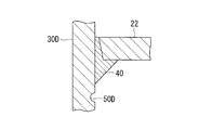
- a step portion 50D of a concave groove portion having a substantially semicircular cross section as a shape displacement point is formed.
- the step portion 50D in this case may be combined with the tapered welded portion 40 or may be combined with the R-shaped welded portion 40A.
- one step portion is added to the welded portion to form a total of two shape displacement points.
- the number of step portions is not limited to one, and 2 It is good also as more than a location.
- the welded portion may be either a tapered surface or an R shape, and the one or more step portions combined therewith are one or more types selected from a tapered surface, an R shape or a groove having a substantially semicircular cross section. Adoption is possible.
- the welded structure described above is not limited to the top plate 22 of the tire manufacturing apparatus 10 described above.
- the bottom plate of the lower dome 12 mounted in the pressure vessel of the tire manufacturing apparatus 10 is, of course, other
- the present invention can also be applied to various plate materials attached to the inside of the pressure vessel.
- this invention is not limited to embodiment mentioned above, In the range which does not deviate from the summary, it can change suitably.
Landscapes
- Engineering & Computer Science (AREA)
- Mechanical Engineering (AREA)
- General Engineering & Computer Science (AREA)
- Physics & Mathematics (AREA)
- Quality & Reliability (AREA)
- Thermal Sciences (AREA)
- Oral & Maxillofacial Surgery (AREA)
- Health & Medical Sciences (AREA)
- Plasma & Fusion (AREA)
- Pressure Vessels And Lids Thereof (AREA)
- Filling Or Discharging Of Gas Storage Vessels (AREA)
- Butt Welding And Welding Of Specific Article (AREA)
- Moulds For Moulding Plastics Or The Like (AREA)
- Heating, Cooling, Or Curing Plastics Or The Like In General (AREA)
Abstract
Description
このような溶接部3は、溶接部の応力集中を緩和するため、テーパ形状やR形状等を形成する露出面4となるように、機械加工が施されている。
なお、上述した溶接部3をR形状に機械加工することは、たとえば下記の特許文献1に開示されている。
一方、溶接の入熱量は、板材1と溶接される壁面部材2の板厚tによる制限を受ける。このため、上述したテーパ面やR形状によって応力集中を緩和しようとすると、溶接量の増加に加えて、壁面部材2の板厚tも増加するという問題が生じてくる。
本発明に係る圧力容器は、容器本体の内部を仕切るように取り付けられて圧力や荷重を受ける部材の端部が、前記容器本体の壁面部材に溶接をして取り付けられる溶接構造部を有する圧力容器であって、前記溶接構造部に前記溶接部を含む少なくとも2箇所の形状変位点を設けたことを特徴とするものである。
すなわち、溶接構造部は、溶接部の溶接量を増大させるテーパ形状やR形状等の延長による溶接部の応力集中緩和を回避できるようになるため、溶接費や溶接歪みの低減が可能になり、さらに、壁面部材となる胴板や鏡板は、溶接量の増大がないため、入熱量の制限による板厚増加もなくなり、材料費、製缶費及び輸送費の低減が可能になる。
ここで、本発明に係る圧力容器の適用例として、タイヤ製造装置(タイヤ加硫機)の構造例を図3に示す。図示のタイヤ製造装置10は、たとえば建設機械等の大型車両用タイヤの加硫に使用されるオートクレーブ(あるいはホットヒーター)と称する装置である。このタイヤ製造装置10は、日本国内の場合、第一種圧力容器構造規格に基づいて製造される圧力容器である。
加硫するグリーンタイヤ15を収納したモールド16は、モールドテーブル17上に3~4段重ねられる。なお、図中の符号18はプレス力を伝達するラム、19はグリーンタイヤ15に温水及び冷却水を供給するフレキシブルホース、20,21はフレキシブルホース19を介して供給される温水及び冷却水をグリーンタイヤ15に噴射して冷却するノズルである。
この天板22は、たとえば図1に示すように、板材の端部が容器本体の円筒形上部を形成する壁面部材30に対して、略T字形断面となるように溶接をして取り付けられている。以下の説明では、壁面部材30に天板22を溶接した溶接部を溶接部40と呼ぶことにする。
そして、本実施形態の圧力容器は、容器本体の内部を仕切るように取り付けられて圧力や荷重を受ける天板22の端部が、容器本体の壁面部材30に対し溶接部40で取り付けられた図示の溶接構造部を有し、この溶接構造部に溶接部40を含む少なくとも2箇所の形状変位点を設けてある。
図1Aは、図1Bに示す溶接後の状態にある溶接部40′から機械加工を施した機械加工後の最終形状を示している。すなわち、溶接後の溶接部40′は溶接脚長がWとされ、この状態から機械加工を受けて最終形状の溶接部40となり、さらに、溶接部40の下方には機械加工により板厚tを厚さdだけ薄くした板厚変位点の段差部50が形成されている。なお、本実施形態の溶接部40は、露出面42がテーパ面を形成するように機械加工されている。
ここで、L0、L1、L2及びdは、溶接後の溶接脚長、すなわち機械加工前の溶接脚長をWとすれば、0≦L0≦W、0≦L1≦5L0、0≦L2≦9L0-L1、0≦d≦0.8tとなるように設定されている。なお、溶接部40′については、必ずしも機械加工を施す必要はなく、従って、図1Bに示す溶接脚長Wは、天板22の下面から溶接止端41までの距離のL0以上(W≧L0)あればよい。
この結果、本実施形態の溶接構造部を有する圧力容器は、機械寿命の向上により優れた耐久性や信頼性を有するものとなる。
図4に示す溶接構造部の第1変形例では、壁面部材30Aの板厚を減じて形状変更開始点51から形状変更終了点52に至るR形状の段差部50Aが形成されている。このような段差部50Aを設けても、上述した露出面42がテーパ面の段差部50と同様の作用効果を得ることができる。
図6に示す第3変形例は、図1Aにおける溶接止端41から段差部50が開始される形状変更開始点51までの距離であるL1をなくして0とし、溶接止端41及び形状変更開始点51が一致したものであり、機械加工により溶接部40′及び壁面部材30Bに連続するR形状が形成されている。この場合の形状変位点は、機械加工後に露出面42BがR形状となる溶接部40Bと、同じく機械加工後にR形状となる段差部50Bとの2箇所である。なお、溶接部40B及び壁面部材30Bに連続するR形状に代えて、連続するテーパ面としてもよい。
図7Aに示す第4変形例では、図中に想像線で示す溶接後の溶接部40′及び壁面部材30′から機械加工を施し、R形状の溶接部40A及びテーパ面の段差部50による2箇所の形状変位点を形成している。この場合、天板22の下面から溶接止端41までの距離L0は、溶接脚長Wより小(L0<W)である。
図7Cに示す第6変形例では、図中に想像線で示す溶接後の溶接部40′及び壁面部材30′から機械加工を施し、テーパ面の溶接部40及びテーパ面の段差部50による2箇所の形状変位点を形成している。この場合、天板22の下面から溶接止端41までの距離L0は、溶接脚長Wより小(L0<W)である。
また、上述した実施形態では、溶接部に1箇所の段差部を加えて合計2箇所の形状変位点を形成しているが、段差部の数については1箇所に限定されることはなく、2箇所以上としてもよい。この場合、溶接部はテーパ面またはR形状のいずれでもよく、また、これと組み合わせる1または複数の段差部は、テーパ面、R形状または略半円形断面の凹溝から選択した1または複数種類の採用が可能である。
なお、本発明は上述した実施形態に限定されることはなく、その要旨を逸脱しない範囲内において適宜変更することができる。
11 上ドーム
12 下ドーム
13 連結環
14 シリンダ
15 グリーンタイヤ
16 モールド
22 天板
30,30A,30B,30D,30′ 壁面部材
40,40A~40C,40′ 溶接部
50,50A~50D 段差部
Claims (2)
- 容器本体の内部を仕切るように取り付けられて圧力や荷重を受ける部材の端部が、前記容器本体の壁面部材に溶接をして取り付けられる溶接構造部を有する圧力容器であって、前記溶接構造部に前記溶接部を含む少なくとも2箇所の形状変位点を設けた圧力容器。
- 容器の内部でタイヤの加硫を行うタイヤ製造装置に用いられる請求項1に記載の圧力容器。
Priority Applications (3)
| Application Number | Priority Date | Filing Date | Title |
|---|---|---|---|
| KR1020127028594A KR101446405B1 (ko) | 2011-02-25 | 2011-05-09 | 압력 용기 |
| CN201180023043.6A CN102893064B (zh) | 2011-02-25 | 2011-05-09 | 压力容器 |
| US13/699,990 US9028234B2 (en) | 2011-02-25 | 2011-05-09 | Pressure vessel |
Applications Claiming Priority (2)
| Application Number | Priority Date | Filing Date | Title |
|---|---|---|---|
| JP2011040723A JP5622615B2 (ja) | 2011-02-25 | 2011-02-25 | 圧力容器 |
| JP2011-040723 | 2011-02-25 |
Publications (1)
| Publication Number | Publication Date |
|---|---|
| WO2012114540A1 true WO2012114540A1 (ja) | 2012-08-30 |
Family
ID=46720351
Family Applications (1)
| Application Number | Title | Priority Date | Filing Date |
|---|---|---|---|
| PCT/JP2011/060670 Ceased WO2012114540A1 (ja) | 2011-02-25 | 2011-05-09 | 圧力容器 |
Country Status (6)
| Country | Link |
|---|---|
| US (1) | US9028234B2 (ja) |
| JP (1) | JP5622615B2 (ja) |
| KR (1) | KR101446405B1 (ja) |
| CN (1) | CN102893064B (ja) |
| TW (1) | TWI461337B (ja) |
| WO (1) | WO2012114540A1 (ja) |
Families Citing this family (4)
| Publication number | Priority date | Publication date | Assignee | Title |
|---|---|---|---|---|
| JP2015093318A (ja) * | 2013-11-14 | 2015-05-18 | 国立大学法人九州大学 | 溶接継手及び溶接部の疲労強度向上方法 |
| JP2016207960A (ja) * | 2015-04-28 | 2016-12-08 | 小島プレス工業株式会社 | ソーラーパネル及びその製造方法 |
| JP7009748B2 (ja) * | 2016-08-18 | 2022-01-26 | 日本製鉄株式会社 | 重ね隅肉溶接継手 |
| CN109570935B (zh) * | 2019-01-03 | 2020-01-14 | 上海江南船舶管业有限公司 | 压力筒焊接工艺 |
Citations (4)
| Publication number | Priority date | Publication date | Assignee | Title |
|---|---|---|---|---|
| JPH0129050Y2 (ja) * | 1982-10-14 | 1989-09-05 | ||
| JPH1034328A (ja) * | 1996-07-19 | 1998-02-10 | Mitsubishi Heavy Ind Ltd | 耐低サイクル疲労すみ肉溶接方法 |
| JP2005088048A (ja) * | 2003-09-17 | 2005-04-07 | Toshiba Plant Systems & Services Corp | 配管継手用溶接歪吸収フランジおよび配管継手 |
| JP2008221300A (ja) * | 2007-03-14 | 2008-09-25 | Press Kogyo Co Ltd | 隅肉溶接部の構造及び隅肉溶接方法 |
Family Cites Families (2)
| Publication number | Priority date | Publication date | Assignee | Title |
|---|---|---|---|---|
| US3917440A (en) * | 1975-02-07 | 1975-11-04 | Ben R Huebert | Tire curing chamber |
| CN201554848U (zh) | 2009-12-08 | 2010-08-18 | 王行山 | 球形压力容器 |
-
2011
- 2011-02-25 JP JP2011040723A patent/JP5622615B2/ja not_active Expired - Fee Related
- 2011-05-09 US US13/699,990 patent/US9028234B2/en not_active Expired - Fee Related
- 2011-05-09 KR KR1020127028594A patent/KR101446405B1/ko not_active Expired - Fee Related
- 2011-05-09 WO PCT/JP2011/060670 patent/WO2012114540A1/ja not_active Ceased
- 2011-05-09 CN CN201180023043.6A patent/CN102893064B/zh not_active Expired - Fee Related
-
2012
- 2012-01-30 TW TW101102863A patent/TWI461337B/zh not_active IP Right Cessation
Patent Citations (4)
| Publication number | Priority date | Publication date | Assignee | Title |
|---|---|---|---|---|
| JPH0129050Y2 (ja) * | 1982-10-14 | 1989-09-05 | ||
| JPH1034328A (ja) * | 1996-07-19 | 1998-02-10 | Mitsubishi Heavy Ind Ltd | 耐低サイクル疲労すみ肉溶接方法 |
| JP2005088048A (ja) * | 2003-09-17 | 2005-04-07 | Toshiba Plant Systems & Services Corp | 配管継手用溶接歪吸収フランジおよび配管継手 |
| JP2008221300A (ja) * | 2007-03-14 | 2008-09-25 | Press Kogyo Co Ltd | 隅肉溶接部の構造及び隅肉溶接方法 |
Also Published As
| Publication number | Publication date |
|---|---|
| TW201302564A (zh) | 2013-01-16 |
| KR101446405B1 (ko) | 2014-10-01 |
| CN102893064B (zh) | 2015-07-29 |
| US20130337097A1 (en) | 2013-12-19 |
| JP5622615B2 (ja) | 2014-11-12 |
| CN102893064A (zh) | 2013-01-23 |
| KR20130025393A (ko) | 2013-03-11 |
| TWI461337B (zh) | 2014-11-21 |
| US9028234B2 (en) | 2015-05-12 |
| JP2012177432A (ja) | 2012-09-13 |
Similar Documents
| Publication | Publication Date | Title |
|---|---|---|
| JP5622615B2 (ja) | 圧力容器 | |
| DK2886994T3 (en) | PLATE HEAT EXCHANGERS WITH ASSEMBLY FLANGES | |
| US9206549B2 (en) | Steel-made yankee cylinder | |
| JP6207635B2 (ja) | ギヤボックスハウジングおよびギヤボックスハウジングの製造方法 | |
| FI4098432T3 (fi) | Radiaalipuristin | |
| KR20120049938A (ko) | 실린더 헤드 개스킷 | |
| EP2672214A1 (en) | End-piece & plate heat exchanger comprising, and method of making, such end-piece | |
| JP5694564B2 (ja) | 溶接の残留応力低減 | |
| US20140322007A1 (en) | Turbine diaphragm construction | |
| CN107433306A (zh) | 一种用于车辆的整体式桥壳的成型方法 | |
| CN104668804B (zh) | 一种火箭推进剂贮箱的箱底与筒段的对接结构 | |
| JP6813589B2 (ja) | 風力原動機に用いられる支持構造 | |
| KR20070049084A (ko) | 복류 증기 터빈용 유동 분리기 및 복류 증기 터빈 | |
| CN103620127B (zh) | 波纹钢板的设计方法、及波纹钢板制管 | |
| CN110588910B (zh) | 一种柔性水上浮体 | |
| JP7180397B2 (ja) | 空気式防舷材およびその製造方法 | |
| JP4485700B2 (ja) | 分割フランジ付き伸縮管継手 | |
| JP2016204008A (ja) | 浮き屋根式タンク用シール材 | |
| JP4812558B2 (ja) | 熱交換器の製造方法 | |
| CN102729518B (zh) | 液压机、用于液压机的缸梁结构及其制造方法 | |
| CN211463180U (zh) | 一种组合式填料环 | |
| JP5858341B2 (ja) | 筒状ライニング材の絞り治具及び筒状ライニング材の取り外し方法 | |
| CN102358404A (zh) | 船用护舷结构 | |
| JP2010053694A (ja) | エンジン本体構造 | |
| CN107923420A (zh) | 流体压缸 |
Legal Events
| Date | Code | Title | Description |
|---|---|---|---|
| WWE | Wipo information: entry into national phase |
Ref document number: 201180023043.6 Country of ref document: CN |
|
| 121 | Ep: the epo has been informed by wipo that ep was designated in this application |
Ref document number: 11859183 Country of ref document: EP Kind code of ref document: A1 |
|
| ENP | Entry into the national phase |
Ref document number: 20127028594 Country of ref document: KR Kind code of ref document: A |
|
| WWE | Wipo information: entry into national phase |
Ref document number: 2598/MUMNP/2012 Country of ref document: IN |
|
| WWE | Wipo information: entry into national phase |
Ref document number: 13699990 Country of ref document: US |
|
| NENP | Non-entry into the national phase |
Ref country code: DE |
|
| 122 | Ep: pct application non-entry in european phase |
Ref document number: 11859183 Country of ref document: EP Kind code of ref document: A1 |