WO2012114651A1 - Polyacrylonitrile modifié par du soufre et son procédé d'évaluation, électrode positive utilisant du polyacrylonitrile modifié par du soufre, batterie secondaire à électrolyte non aqueux, et véhicule - Google Patents
Polyacrylonitrile modifié par du soufre et son procédé d'évaluation, électrode positive utilisant du polyacrylonitrile modifié par du soufre, batterie secondaire à électrolyte non aqueux, et véhicule Download PDFInfo
- Publication number
- WO2012114651A1 WO2012114651A1 PCT/JP2012/000414 JP2012000414W WO2012114651A1 WO 2012114651 A1 WO2012114651 A1 WO 2012114651A1 JP 2012000414 W JP2012000414 W JP 2012000414W WO 2012114651 A1 WO2012114651 A1 WO 2012114651A1
- Authority
- WO
- WIPO (PCT)
- Prior art keywords
- sulfur
- modified polyacrylonitrile
- polyacrylonitrile
- positive electrode
- secondary battery
- Prior art date
- Legal status (The legal status is an assumption and is not a legal conclusion. Google has not performed a legal analysis and makes no representation as to the accuracy of the status listed.)
- Ceased
Links
Images


Classifications
-
- H—ELECTRICITY
- H01—ELECTRIC ELEMENTS
- H01M—PROCESSES OR MEANS, e.g. BATTERIES, FOR THE DIRECT CONVERSION OF CHEMICAL ENERGY INTO ELECTRICAL ENERGY
- H01M10/00—Secondary cells; Manufacture thereof
- H01M10/05—Accumulators with non-aqueous electrolyte
-
- C—CHEMISTRY; METALLURGY
- C08—ORGANIC MACROMOLECULAR COMPOUNDS; THEIR PREPARATION OR CHEMICAL WORKING-UP; COMPOSITIONS BASED THEREON
- C08F—MACROMOLECULAR COMPOUNDS OBTAINED BY REACTIONS ONLY INVOLVING CARBON-TO-CARBON UNSATURATED BONDS
- C08F8/00—Chemical modification by after-treatment
- C08F8/34—Introducing sulfur atoms or sulfur-containing groups
-
- H—ELECTRICITY
- H01—ELECTRIC ELEMENTS
- H01M—PROCESSES OR MEANS, e.g. BATTERIES, FOR THE DIRECT CONVERSION OF CHEMICAL ENERGY INTO ELECTRICAL ENERGY
- H01M4/00—Electrodes
- H01M4/02—Electrodes composed of, or comprising, active material
- H01M4/36—Selection of substances as active materials, active masses, active liquids
- H01M4/60—Selection of substances as active materials, active masses, active liquids of organic compounds
- H01M4/602—Polymers
- H01M4/604—Polymers containing aliphatic main chain polymers
-
- C—CHEMISTRY; METALLURGY
- C08—ORGANIC MACROMOLECULAR COMPOUNDS; THEIR PREPARATION OR CHEMICAL WORKING-UP; COMPOSITIONS BASED THEREON
- C08F—MACROMOLECULAR COMPOUNDS OBTAINED BY REACTIONS ONLY INVOLVING CARBON-TO-CARBON UNSATURATED BONDS
- C08F220/00—Copolymers of compounds having one or more unsaturated aliphatic radicals, each having only one carbon-to-carbon double bond, and only one being terminated by only one carboxyl radical or a salt, anhydride ester, amide, imide or nitrile thereof
- C08F220/02—Monocarboxylic acids having less than ten carbon atoms; Derivatives thereof
- C08F220/42—Nitriles
- C08F220/44—Acrylonitrile
-
- Y—GENERAL TAGGING OF NEW TECHNOLOGICAL DEVELOPMENTS; GENERAL TAGGING OF CROSS-SECTIONAL TECHNOLOGIES SPANNING OVER SEVERAL SECTIONS OF THE IPC; TECHNICAL SUBJECTS COVERED BY FORMER USPC CROSS-REFERENCE ART COLLECTIONS [XRACs] AND DIGESTS
- Y02—TECHNOLOGIES OR APPLICATIONS FOR MITIGATION OR ADAPTATION AGAINST CLIMATE CHANGE
- Y02E—REDUCTION OF GREENHOUSE GAS [GHG] EMISSIONS, RELATED TO ENERGY GENERATION, TRANSMISSION OR DISTRIBUTION
- Y02E60/00—Enabling technologies; Technologies with a potential or indirect contribution to GHG emissions mitigation
- Y02E60/10—Energy storage using batteries
Definitions
- the present invention relates to sulfur-modified polyacrylonitrile suitably used as a positive electrode active material for a non-aqueous electrolyte secondary battery, and an evaluation method thereof.
- a lithium ion secondary battery which is a type of non-aqueous electrolyte secondary battery, is a battery with a large charge / discharge capacity, and is mainly used as a battery for portable electronic devices. Lithium ion secondary batteries are also expected as batteries for electric vehicles.
- a positive electrode active material of a lithium ion secondary battery As a positive electrode active material of a lithium ion secondary battery, a material containing a rare metal such as cobalt or nickel is generally used. However, since these metals have a small circulation amount and are expensive, in recent years, a positive electrode active material using a substance replacing these rare metals has been demanded.
- the charge / discharge capacity of the lithium ion secondary battery can be increased.
- the charge / discharge capacity of a lithium ion secondary battery using sulfur as a positive electrode active material is approximately six times the charge / discharge capacity of a lithium ion secondary battery using a lithium cobaltate positive electrode material, which is a common positive electrode material. is there.
- a compound of sulfur and lithium is generated during discharge.
- This compound of sulfur and lithium is soluble in a non-aqueous electrolyte solution (for example, ethylene carbonate, dimethyl carbonate, etc.) of a lithium ion secondary battery.
- a lithium ion secondary battery using sulfur as a positive electrode active material has a problem that, when charging and discharging are repeated, it gradually deteriorates due to elution of sulfur into the electrolytic solution, and the battery capacity decreases.
- cycle characteristic the characteristic of the lithium ion secondary battery in which the charge / discharge capacity decreases with repeated charge / discharge.
- the lithium ion secondary battery having a small decrease in charge / discharge capacity is a lithium ion secondary battery having excellent cycle characteristics, and the lithium ion secondary battery having a large decrease in charge / discharge capacity is a lithium ion secondary battery having inferior cycle characteristics.
- Patent Document 1 introduces a technique of using polysulfide carbon having carbon and sulfur as main constituent elements as a positive electrode active material.
- This polysulfide carbon is obtained by adding sulfur to a linear unsaturated polymer. According to this technique, elution of sulfur into the electrolytic solution can be suppressed by the carbon material. For this reason, it is thought that the cycle characteristic of the lithium ion secondary battery which uses this polysulfide carbon as a positive electrode active material improves. However, even with a lithium ion secondary battery using carbon polysulfide as the positive electrode active material, no significant improvement in cycle characteristics was observed.
- the inventors of the present invention invented a positive electrode active material obtained by heat-treating a mixture of polyacrylonitrile and sulfur (see Patent Document 2).
- the charge / discharge capacity of a lithium ion secondary battery using this positive electrode active material for the positive electrode is large, and the lithium ion secondary battery using this positive electrode active material for the positive electrode is excellent in cycle characteristics.
- lithium ion secondary batteries using sulfur-modified polyacrylonitrile as a positive electrode active material sometimes have different charge / discharge capacities depending on the polyacrylonitrile manufacturer and product lot. Therefore, in order to reduce the uneven quality of the lithium ion secondary battery, it is necessary to select and use sulfur-modified polyacrylonitrile suitable as a positive electrode active material for the lithium ion secondary battery.
- JP 2002-154815 A International Publication No. 2010/044437
- the present invention has been made in view of the above circumstances, sulfur-modified polyacrylonitrile capable of improving the charge / discharge capacity of a lithium ion secondary battery, and an evaluation method for selecting such sulfur-modified polyacrylonitrile, and
- An object is to provide a positive electrode using the sulfur-modified polyacrylonitrile, a non-aqueous electrolyte secondary battery, and a vehicle equipped with the non-aqueous electrolyte secondary battery.
- the sulfur-modified polyacrylonitrile of the present invention that solves the above problems is A sulfur-modified polyacrylonitrile made from sulfur and polyacrylonitrile, A region occupied by particles having a particle diameter of 1 ⁇ m or less and / or an aggregate of the particles in the whole particle is 80% or more in terms of an imaging area ratio.
- Another sulfur-modified polyacrylonitrile of the present invention that solves the above problems is a sulfur-modified polyacrylonitrile using sulfur and polyacrylonitrile as a material,
- the polyacrylonitrile is produced by a method other than emulsion polymerization.
- the positive electrode for a non-aqueous electrolyte secondary battery of the present invention that solves the above-mentioned problems is characterized by containing the sulfur-modified polyacrylonitrile of the present invention as a positive electrode active material.
- the non-aqueous electrolyte secondary battery of the present invention that solves the above problems includes the sulfur-modified polyacrylonitrile of the present invention in the positive electrode as a positive electrode active material.
- a vehicle of the present invention that solves the above-described problems is characterized by mounting the nonaqueous electrolyte secondary battery of the present invention.
- the method for evaluating the sulfur-modified polyacrylonitrile of the present invention that solves the above problems is as follows.
- An evaluation method for sulfur-modified polyacrylonitrile used as a positive electrode active material for a non-aqueous electrolyte secondary battery Of all the particles, particles having a particle diameter of 1 ⁇ m or less and / or an area occupied by the aggregate of the particles are determined as conforming products when the imaging area ratio is 80% or more, and the other regions are regarded as non-conforming products. It is characterized by evaluating.
- the method for producing a non-aqueous electrolyte secondary battery of the present invention that solves the above problems includes the method for evaluating sulfur-modified polyacrylonitrile of the present invention.
- the nonaqueous electrolyte secondary battery using the sulfur-modified polyacrylonitrile of the present invention has a large charge / discharge capacity. Further, according to the method for evaluating sulfur-modified polyacrylonitrile of the present invention, sulfur-modified polyacrylonitrile that can improve the charge / discharge capacity of the non-aqueous electrolyte secondary battery can be selected. Therefore, if the method for evaluating sulfur-modified polyacrylonitrile of the present invention is used, sulfur-modified polyacrylonitrile that can be used for a non-aqueous electrolyte secondary battery having a large charge / discharge capacity can be produced.
- a non-aqueous electrolyte secondary battery having a large charge / discharge capacity can be produced. Furthermore, since the vehicle of the present invention is equipped with the above-described nonaqueous electrolyte secondary battery of the present invention, it is excellent in various characteristics that require electric power.
- FIG. 6 is a SEM image of the surface of sulfur-modified polyacrylonitrile of sample 5.
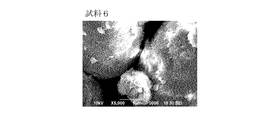
- 2 is an SEM image of the surface of sulfur-modified polyacrylonitrile of Sample 6.
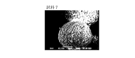
- 3 is a SEM image of the surface of sulfur-modified polyacrylonitrile of Sample 7.
- 2 is a SEM image of the surface of a sulfur-modified polyacrylonitrile of sample 8.
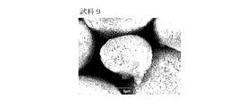
- 2 is an SEM image of the surface of sulfur-modified polyacrylonitrile of sample 9.
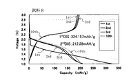
- 3 is a graph showing a charge / discharge curve of a lithium ion secondary battery of Sample 1.
- FIG. 4 is a graph showing cycle characteristics of a lithium ion secondary battery of Sample 1.
- 5 is a graph showing a charge / discharge curve of a lithium ion secondary battery of Sample 8.
- FIG. 4 is a graph showing cycle characteristics of a lithium ion secondary battery of Sample 1.
- 5 is a graph showing a charge / discharge curve of a lithium ion secondary battery of Sample 8.
- 4 is a graph showing the result of analyzing the sulfur-modified polyacrylonitrile of Sample 1 by FT-IR.
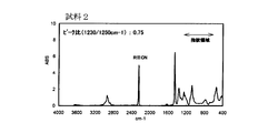
- 4 is a graph showing the result of analyzing the sulfur-modified polyacrylonitrile of Sample 2 by FT-IR.
- 4 is a graph showing the result of analyzing the sulfur-modified polyacrylonitrile of Sample 3 by FT-IR.
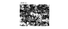
- 6 is a graph showing the result of analyzing the sulfur-modified polyacrylonitrile of Sample 4 by FT-IR.
- 6 is a graph showing the result of analyzing the sulfur-modified polyacrylonitrile of Sample 5 by FT-IR.
- 6 is a graph showing the result of analyzing the sulfur-modified polyacrylonitrile of Sample 6 by FT-IR.
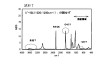
- 6 is a graph showing the result of analyzing the sulfur-modified polyacrylonitrile of Sample 7 by FT-IR.
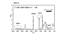
- 6 is a graph showing the result of analyzing the sulfur-modified polyacrylonitrile of Sample 8 by FT-IR.
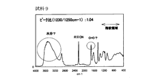
- 6 is a graph showing the result of analyzing the sulfur-modified polyacrylonitrile of Sample 9 by FT-IR.
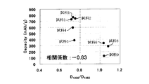
- 10 is a graph showing the relationship between the absorbance ratio (D 1230 / D 1250 ) of the sulfur-modified polyacrylonitrile of Samples 1 to 9 by FT-IR and the second discharge capacity.
- 3 is a graph showing the result of thermal mass-differential thermal analysis of sulfur-modified polyacrylonitrile of Sample 1.
- 4 is a graph showing the results of thermal mass-differential thermal analysis of sulfur-modified polyacrylonitrile of Sample 2.
- 4 is a graph showing the result of thermal mass-differential thermal analysis of sulfur-modified polyacrylonitrile of Sample 3.
- 4 is a graph showing the result of thermal mass-differential thermal analysis of sulfur-modified polyacrylonitrile of Sample 4.
- 6 is a graph showing the result of thermal mass-differential thermal analysis of sulfur-modified polyacrylonitrile of Sample 5.
- 6 is a graph showing the result of thermal mass-differential thermal analysis of sulfur-modified polyacrylonitrile of Sample 6.
- 6 is a graph showing the result of thermal mass-differential thermal analysis of sulfur-modified polyacrylonitrile of Sample 7.
- 6 is a graph showing the result of thermal mass-differential thermal analysis of sulfur-modified polyacrylonitrile of Sample 8.
- 6 is a graph showing the result of thermal mass-differential thermal analysis of sulfur-modified polyacrylonitrile of Sample 9.
- the positive electrode for a nonaqueous electrolyte secondary battery of the present invention contains the sulfur-modified polyacrylonitrile of the present invention as a positive electrode active material in the positive electrode.
- the nonaqueous electrolyte secondary battery of the present invention is a battery using the positive electrode of the present invention, and contains the sulfur-modified polyacrylonitrile of the present invention as a positive electrode active material in the positive electrode.
- the sulfur-modified polyacrylonitrile of the present invention is the same as that disclosed in Patent Document 2 above. Specifically, the sulfur-modified polyacrylonitrile of the present invention is made of sulfur and polyacrylonitrile, and contains carbon element (C) and sulfur element (S).
- polyacrylonitrile is abbreviated as PAN as necessary.
- Polyacrylonitrile as a material for sulfur-modified polyacrylonitrile is preferably in the form of a powder, and preferably has a mass average molecular weight of about 10 4 to 3 ⁇ 10 5 .
- the particle size of polyacrylonitrile is preferably about 0.5 to 50 ⁇ m, more preferably about 1 to 10 ⁇ m, when observed with an electron microscope. If the molecular weight and particle size of polyacrylonitrile are within these ranges, the contact area between polyacrylonitrile and sulfur can be increased, and polyacrylonitrile and sulfur can be reacted with high reliability. For this reason, the elution of sulfur to the electrolytic solution can be more reliably suppressed.
- sulfur-modified polyacrylonitrile As the positive electrode active material of a lithium ion secondary battery, the high capacity inherent in sulfur can be maintained, and elution of sulfur into the electrolyte is suppressed, so the cycle characteristics are greatly improved. . This is presumably because sulfur does not exist as a simple substance in sulfur-modified polyacrylonitrile, but exists in a stable state combined with polyacrylonitrile.
- sulfur is heat-processed with polyacrylonitrile. When polyacrylonitrile is heated, it is considered that polyacrylonitrile is three-dimensionally crosslinked to form a condensed ring (mainly a 6-membered ring) and close the ring.
- sulfur-modified polyacrylonitrile has a carbon skeleton derived from polyacrylonitrile.
- the method for producing polyacrylonitrile includes a step of polymerizing an acrylonitrile monomer (hereinafter simply referred to as a monomer).
- a monomer acrylonitrile monomer
- general polymerization methods include bulk polymerization, suspension polymerization, solution polymerization, and emulsion polymerization.
- Bulk polymerization is a method in which polymerization is carried out by adding only a monomer or a small amount of a polymerization initiator to the monomer without using a solvent.
- the product is mainly composed of a polymer and an unreacted monomer, and contains impurities derived from a polymerization initiator, but is pure as compared with other polymerization methods.
- the viscosity of the reaction system increases with the progress of polymerization, and stirring and flow (removal from the reactor) and removal of heat of reaction become difficult.
- Suspension polymerization is a polymerization method in which a monomer and a solvent (water) are mechanically stirred and suspended for polymerization.
- a radical generator soluble in the monomer as the polymerization initiator.
- the polymerization disclosure agent is present in the monomer droplets dispersed in the solvent. For this reason, the polymerization reaction proceeds in a state close to a bulk polymerization occurring in each monomer droplet. Since the reaction occurs in the monomer droplets, there is an advantage that a polymer having a small molecular weight (that is, a small particle size) and few impurities can be obtained.
- Solution polymerization is a method in which a polymerization reaction is performed in a solvent.
- a solvent that does not easily react with either the monomer or the catalyst (polymerization initiator) is used. According to this method, since the solvent absorbs heat, the reaction heat of polymerization is easy to adjust, but the reaction rate is slow. Since it is difficult to manage the solvent, it is not an industrially used method. It is technically difficult to produce a solution polymerized product having a uniform particle size.
- Emulsion polymerization is a type of radical polymerization.
- a polymerization initiator usually a radical generator
- a medium such as water
- a monomer that is hardly soluble in the medium and an emulsifier (surfactant).
- emulsifier surfactant
- Emulsion polymerization is suitable for making the particle shape uniformly at the submicron level, and is also optimal in terms of production efficiency.
- high molecular weight that is, increase in particle size is unavoidable in emulsion polymerization.
- the polyacrylonitrile obtained by the emulsion polymerization method contains an emulsifier as an impurity.
- acrylamide generated by hydrolysis of acrylonitrile CH 2 ⁇ CHCN
- polyacrylonitrile obtained by emulsion polymerization is not preferable as a material for sulfur-modified polyacrylonitrile for a positive electrode active material. That is, when sulfur-modified polyacrylonitrile using polyacrylonitrile obtained by emulsion polymerization as a raw material is used as a positive electrode active material, sulfur-modified polyacrylonitrile obtained using polyacrylonitrile obtained by other methods as a positive electrode active material Compared with the case where it uses as, the capacity
- polyacrylonitrile produced by a method other than emulsion polymerization (bulk polymerization, suspension polymerization, solution polymerization, etc.).
- Non-conforming PAN Polyacrylonitrile produced by emulsion polymerization
- conforming PAN Polyacrylonitrile produced by other methods
- the particle size of conforming PAN is very small compared to the particle size of non-conforming PAN. This is considered to be because the polymerization reaction proceeds in the micelle formed in the presence of the emulsifier in the emulsion polymerization.
- the particle size of the incompatible PAN produced by emulsion polymerization is a size corresponding to the size of micelles formed in the emulsion polymerization reaction system.
- the particle size of the conforming PAN is as small as approximately 1 ⁇ m or less, whereas the particle size of the nonconforming PAN is a large diameter exceeding 5 ⁇ m.
- the particle size of the sulfur-modified polyacrylonitrile can be measured by the measurement method described later in the column of Examples.
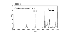
- the incompatible PAN includes acrylamide having a carboxylic acid-based surfactant remaining or synthesized during polymerization. Therefore, when the sulfur-modified polyacrylonitrile is subjected to IR analysis (for example, Fourier transform infrared spectroscopy, FT-IR), a peak derived from C ⁇ O of the carboxylic acid surfactant and / or acrylamide is confirmed. The presence or absence of this peak makes it possible to discriminate between compatible PAN and non-compatible PAN.
- IR analysis for example, Fourier transform infrared spectroscopy, FT-IR
- the absorbance ratio (D 1230 / D 1250 ) by FT-IR is small in the conforming PAN and large in the non-conforming PAN. Specifically, it is 0.75 or less in conforming PAN, and exceeds 0.75 in non-conforming PAN. For this reason, conforming PAN and non-conforming PAN can be distinguished also by the absorbance ratio (D 1230 / D 1250 ) by FT-IR.
- stereoregularity include regularity of configuration and regularity of conformation. Of these, if the regularity of the configuration is low, it becomes atactic. If the regularity of the three-dimensional structure is low, the structure is not a straight chain but an intricate structure. In any case, the lower regularity results in a more complicated structure.
- 13C NMR As a method for measuring stereoregularity, 13C NMR or the like may be used in addition to FT-IR.
- the sulfur used in the sulfur-modified polyacrylonitrile is preferably in the form of a powder, like polyacrylonitrile. Although it does not specifically limit about the particle size of sulfur, When classifying using a sieve, what is in the range of the magnitude
- the blending ratio of the polyacrylonitrile powder and sulfur powder used for the sulfur-modified polyacrylonitrile is not particularly limited, but is preferably 1: 0.5 to 1:10 by mass ratio, and preferably 1: 0.5 to 1: 7 is more preferable, and 1: 2 to 1: 5 is even more preferable.
- sulfur-modified polyacrylonitrile contains carbon, nitrogen, and sulfur, and may contain small amounts of oxygen and hydrogen.
- FIG. 1 As a result of X-ray diffraction of sulfur-modified polyacrylonitrile by CuK ⁇ ray, only a broad peak having a peak position near 25 ° was confirmed in the diffraction angle (2 ⁇ ) range of 20-30 °. It was done.
- X-ray diffraction was measured by X-ray diffraction using CuK ⁇ rays with a powder X-ray diffractometer (manufactured by MAC Science, model number: M06XCE). The measurement conditions were voltage: 40 kV, current: 100 mA, scan speed: 4 ° / min, sampling: 0.02 °, number of integrations: 1, measurement range: diffraction angle (2 ⁇ ) 10 ° -60 °.
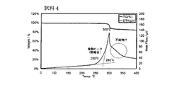
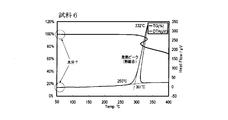
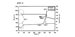
- mass loss by thermogravimetric analysis when sulfur-modified polyacrylonitrile is heated from room temperature to 900 ° C. at a rate of temperature increase of 20 ° C./min is 10% or less at 400 ° C.
- mass loss by thermogravimetric analysis when sulfur-modified polyacrylonitrile is heated from room temperature to 900 ° C. at a rate of temperature increase of 20 ° C./min is 10% or less at 400 ° C.
- mass decrease is recognized from around 120 ° C., and a large mass decrease due to the disappearance of sulfur is recognized suddenly at 200 ° C. or higher.
- sulfur-modified polyacrylonitrile sulfur does not exist as a simple substance, but is considered to exist in a state of being bonded to polyacrylonitrile that has advanced ring closure.
- FIG. 2 An example of the Raman spectrum of sulfur-modified polyacrylonitrile is shown in FIG.
- the Raman spectrum shown in FIG. 2 there are major peak near 1331cm -1 of Raman shift, and, 1548cm -1 in the range of 200cm -1 ⁇ 1800cm -1, 939cm -1 , 479cm -1, 381cm -1, There is a peak near 317 cm ⁇ 1 .
- the Raman shift peak described above is observed at the same position even when the ratio of elemental sulfur to polyacrylonitrile is changed. Thus, these peaks characterize sulfur-modified polyacrylonitrile.
- Each of the peaks described above exists within a range of approximately ⁇ 8 cm ⁇ 1 with the above peak position as the center.
- the “main peak” refers to a peak having the maximum peak height among all peaks appearing in the Raman spectrum.
- the positive electrode of the present invention contains the sulfur-modified polyacrylonitrile of the present invention as a positive electrode active material.
- the positive electrode can have the same structure as a general positive electrode for a non-aqueous electrolyte secondary battery (for example, a positive electrode for a lithium ion secondary battery) except for the positive electrode active material.
- the positive electrode of the present invention can be manufactured by applying a positive electrode material, which is a mixture of sulfur-modified polyacrylonitrile, a conductive additive, a binder, and a solvent, to a current collector.
- a mixed raw material in which sulfur powder and polyacrylonitrile powder are mixed can be heated (a heat treatment step is performed) after filling the positive electrode current collector.
- polyacrylonitrile and sulfur are reacted to obtain sulfur-modified polyacrylonitrile, and at the same time, the sulfur-modified polyacrylonitrile and the current collector can be integrated without using a binder. If no binder is used, the amount of the positive electrode active material per positive electrode mass can be increased, and the capacity per positive electrode mass can be improved.
- vapor grown carbon fiber Vapor Carbon Carbon: VGCF
- carbon powder carbon black (CB)
- acetylene black AB
- ketjen black KB
- graphite positive electrodes such as aluminum and titanium
- VGCF vapor grown carbon fiber
- CB carbon black
- AB acetylene black
- KB ketjen black
- positive electrodes such as aluminum and titanium
- fine metal powders stable in potential examples thereof include fine metal powders stable in potential.
- polyvinylidene fluoride Polyvinylidene: PVDF
- polytetrafluoroethylene PTFE
- SBR styrene-butadiene rubber
- PI polyimide
- PAI polyamideimide
- CMC carboxymethylcellulose
- PVC polyvinylidene fluoride
- PMA methacrylic resin
- PAN polyacrylonitrile
- PPO polyphenylene oxide
- PEO polyethylene oxide
- PE polyethylene
- PP polypropylene
- the solvent examples include N-methyl-2-pyrrolidone, N, N-dimethylformaldehyde, alcohol, water and the like.
- These conductive assistants, binders and solvents may be used as a mixture of plural kinds.
- the amount of these materials to be blended is not particularly limited. For example, it is preferable to blend about 20 to 100 parts by weight of a conductive additive and about 10 to 20 parts by weight of a binder with respect to 100 parts by weight of sulfur-modified polyacrylonitrile.
- a mixture of the sulfur-modified polyacrylonitrile of the present invention, the above-described conductive additive and binder is kneaded with a mortar or a press machine to form a film, and the film mixture is collected with a press machine or the like.
- the positive electrode for a nonaqueous electrolyte secondary battery of the present invention can also be produced by pressure bonding to the body.
- current collectors include aluminum foil, aluminum mesh, punched aluminum sheet, aluminum expanded sheet, stainless steel foil, stainless steel mesh, punched stainless steel sheet, stainless steel expanded sheet, foamed nickel, nickel non-woven fabric, copper foil, copper mesh
- examples thereof include a punching copper sheet, a copper expanded sheet, a titanium foil, a titanium mesh, a carbon nonwoven fabric, and a carbon woven fabric.
- the carbon non-woven fabric / woven fabric current collector made of carbon having a high graphitization degree is suitable as a current collector for sulfur-modified polyacrylonitrile because it does not contain hydrogen and has low reactivity with sulfur.
- pitches that is, by-products such as petroleum, coal, coal tar, etc.
- polyacrylonitrile fiber which are carbon fiber materials
- the nonaqueous electrolyte secondary battery of the present invention preferably contains a conductive material in the positive electrode.
- the conductive material refers to a material that exhibits high electrical conductivity or that can greatly improve the lithium ion conductivity of the positive electrode.
- the electrical conductivity of the entire positive electrode and / or the conductivity of charge carriers such as lithium ions can be improved, and the discharge rate characteristics of the nonaqueous electrolyte secondary battery can be improved.
- the material for the conductive material conductive material
- the conductive material at least one metal selected from the group consisting of a fourth periodic metal, a fifth periodic metal, a sixth periodic metal, and a rare earth element, or a sulfide thereof can be used.
- the 4th periodic metal, the 5th periodic metal, and the 6th periodic metal as used in this specification are based on a periodic table.
- the fourth periodic metal refers to a metal included in the fourth periodic element in the periodic table.
- the conductive material is preferably one that exhibits high electrical conductivity in a sulfide state or that can greatly improve the lithium ion conductivity of the positive electrode.
- the conductive material consists of both the metal and its sulfide, or consists only of the metal sulfide. These conductive material materials preferably contain a large amount of sulfide, and more preferably consist only of sulfide.
- the conductive material and the sulfur-modified polyacrylonitrile are easily combined by blending the metal with the positive electrode in a sulfide state, and the conductive material and the positive electrode active material are dispersed substantially uniformly. Further, by using sulfide as the conductive material, there is an advantage that the ratio of the metal and sulfur in the conductive material can be easily controlled within a desired range.
- Non-aqueous electrolyte secondary battery Non-aqueous electrolyte secondary battery
- the non-aqueous electrolyte secondary battery using the positive electrode of the present invention is simply abbreviated as a non-aqueous electrolyte secondary battery.
- a lithium ion secondary battery using the positive electrode of the present invention is simply abbreviated as a lithium ion secondary battery.
- the positive electrode is as described above.
- the negative electrode active material a known carbon-based material such as lithium metal or graphite, an element that can occlude / release lithium ions and can be alloyed with lithium, and / or a compound containing the element can be used.
- the charge carrier is lithium
- the nonaqueous electrolyte secondary battery of the present invention is a lithium secondary battery, a lithium ion secondary battery, or a lithium polymer secondary battery.
- metallic sodium an element that can occlude / release sodium ions and can be alloyed with sodium, and / or a compound containing the element can also be used.
- the charge carrier is sodium
- the nonaqueous electrolyte secondary battery of the present invention is a sodium secondary battery, a sodium ion secondary battery, or a sodium polymer secondary battery.
- the elements that can be alloyed with lithium are Na, K, Rb, Cs, Fr, Be, Mg, Ca, Sr, Ba, Ra, Ti, Ag, Zn, Cd, Al, Ga, In, Si, It is preferably at least one selected from the group consisting of Ge, Sn, Pb, Sb and Bi. Of these, silicon (Si) or tin (Sn) is particularly preferable.
- the elemental compound having an element capable of alloying with lithium is preferably a silicon compound or a tin compound.
- the silicon compound is preferably SiO x (0.5 ⁇ x ⁇ 1.5). Silicon has a large theoretical capacity, but has a large volume change during charge and discharge. Therefore, it can be used in a compound state (ie, SiO x ) to reduce the volume change.
- a tin alloy Cu—Sn alloy, Co—Sn alloy, etc.
- a tin alloy Cu—Sn alloy, Co—Sn alloy, etc.
- silicon-based materials such as silicon thin films and alloy-based materials such as copper-tin and cobalt-tin can be preferably used.
- the charge carrier is sodium
- hard carbon, soft carbon, or a tin compound as the negative electrode active material.
- a negative electrode active material such as a carbon-based material, a silicon-based material, an alloy-based material, or the like that does not contain lithium, for example, among the negative electrode active materials described above
- a short circuit occurs between the positive and negative electrodes due to the generation of dendrites. It is advantageous in that it is difficult.
- a substance such as Li or Na that is involved in charge / discharge by ionizing and moving between the positive electrode and the negative electrode are not included in either the positive electrode or the negative electrode.
- the charge carrier pre-doping method may be a known method.
- an electrolytic doping method in which a half cell is assembled using metallic lithium as the counter electrode and electrochemically doped with lithium in the negative electrode can be used.
- an adhesive pre-doping method in which a metal lithium foil attached to an electrode is allowed to stand in an electrolytic solution and lithium is doped into the negative electrode by utilizing diffusion of lithium.
- the positive electrode is predoped with lithium, the above-described electrolytic doping method can be used. The same applies to sodium.
- a silicon-based material that is a high-capacity negative electrode material is particularly preferable, and among these, thin-film silicon that is advantageous in terms of capacity per volume due to thin electrode thickness is more preferable.
- an electrolyte obtained by dissolving an alkali metal salt as a supporting electrolyte (supporting salt) in an organic solvent can be used.
- the organic solvent is preferably at least one selected from non-aqueous solvents such as ethylene carbonate, propylene carbonate, dimethyl carbonate, diethyl carbonate, ethyl methyl carbonate, dimethyl ether, ⁇ -butyrolactone, and acetonitrile.
- the charge carrier is lithium
- LiPF 6 , LiBF 4 , LiAsF 6 , LiCF 3 SO 3 , LiI, LiClO 4 or the like can be used as the supporting electrolyte.
- the concentration of the electrolyte may be about 0.5 mol / l to 1.7 mol / l.
- the electrolyte is not limited to liquid.
- the non-aqueous electrolyte secondary battery is a lithium polymer secondary battery
- the electrolyte is in a solid state (for example, a polymer gel).
- the charge carrier is Na
- sodium salts such as NaPF 6 , NaBF 4 , NaAsF 6 , NaCF 3 SO 3 , NaI, NaClO 4 can be used for the electrolyte.
- the nonaqueous electrolyte secondary battery may include a member such as a separator in addition to the above-described negative electrode, positive electrode, and electrolyte.
- the separator is interposed between the positive electrode and the negative electrode, allows ions to move between the positive electrode and the negative electrode, and prevents an internal short circuit between the positive electrode and the negative electrode.
- the separator is also required to have a function of holding an electrolytic solution.
- the separator it is preferable to use a thin, microporous or non-woven membrane made of polyethylene, polypropylene, polyacrylonitrile, aramid, polyimide, cellulose, glass or the like.
- the shape of the nonaqueous electrolyte secondary battery is not particularly limited, and can be various shapes such as a cylindrical shape, a stacked shape, and a coin shape.
- the production method of the present invention includes a step (heat treatment step) of heating a mixed material obtained by mixing the above-described sulfur-modified polyacrylonitrile material (that is, polyacrylonitrile powder and sulfur powder). What is necessary is just to mix a mixing material with general mixing apparatuses, such as a mortar and a ball mill.
- a mixing material one obtained by simply mixing sulfur and a carbon material may be used.
- the mixed raw material may be formed into a pellet shape and used.
- a mixture of polyacrylonitrile powder, sulfur powder and conductive material may be used as a mixed material.
- the sulfur contained in the mixed raw material and the carbon material are combined by heating the mixed raw material in the heat treatment step.
- the heat treatment step may be performed in a closed system or an open system, but in order to suppress the dissipation of sulfur vapor, it is preferably performed in a closed system.
- the atmosphere in which the heat treatment step is performed is not particularly limited, but it is preferably performed in an atmosphere that does not hinder the bonding between the carbon material and sulfur (for example, an atmosphere not containing hydrogen or a non-oxidizing atmosphere).
- an atmosphere not containing hydrogen or a non-oxidizing atmosphere for example, when hydrogen is present in the atmosphere, sulfur in the reaction system reacts with hydrogen to form hydrogen sulfide, so that sulfur in the reaction system may be lost.
- the vaporized sulfur reacts with the polyacrylonitrile at the same time as the polyacrylonitrile ring-closing reaction by heat treatment in a non-oxidizing atmosphere. It is believed that polyacrylonitrile is obtained.
- the non-oxidizing atmosphere referred to here includes a reduced pressure state in which the oxygen concentration is low enough not to cause an oxidation reaction, an inert gas atmosphere such as nitrogen or argon, a sulfur gas atmosphere, and the like.
- the mixed raw material is placed in a container that is kept tight enough not to dissipate sulfur vapor, and the inside of the container is decompressed.
- heating may be performed in an inert gas atmosphere.
- the mixed raw material may be heated in a vacuum packaged state with a material that does not easily react with sulfur vapor (for example, an aluminum laminate film).
- the packaged raw material is put in a pressure vessel such as an autoclave containing water and heated, and the generated steam is added from the outside of the packaging material. It is preferable to press. According to this method, since pressure is applied by water vapor from the outside of the packaging material, the packaging material is prevented from being swollen and damaged by sulfur vapor.
- the heating time of the mixed raw material in the heat treatment step may be appropriately set according to the heating temperature, and is not particularly limited.
- the preferable heating temperature mentioned above should just be temperature which the coupling
- the heating temperature is preferably 250 ° C. or more and 500 ° C. or less, more preferably 250 ° C. or more and 400 ° C. or less, and further preferably 300 ° C. or more and 400 ° C. or less.
- the mixed raw material may be heated so that a part of the mixed raw material becomes a gas and a part becomes a liquid.
- the temperature of the mixed raw material may be a temperature equal to or higher than the temperature at which sulfur is vaporized.
- Vaporization here refers to the phase change of sulfur from a liquid or solid to a gas, and may be any of boiling, evaporation, and sublimation.
- the melting point of ⁇ sulfur orthogonal sulfur, which is the most stable structure near room temperature
- the melting point of ⁇ sulfur (monoclinic sulfur) is 119.6 ° C.
- ⁇ sulfur monoclinic sulfur
- the object to be treated may be used as it is as sulfur-modified polyacrylonitrile.
- unit sulfur removal as sulfur modified polyacrylonitrile, when removing single-piece
- the sulfur-modified polyacrylonitrile, the positive electrode for a non-aqueous electrolyte secondary battery, the non-aqueous electrolyte secondary battery, and the evaluation method for the sulfur-modified polyacrylonitrile of the present invention will be specifically described.
- the reaction apparatus 1 includes a reaction vessel 2, a lid 3, a thermocouple 4, an alumina protective tube 40, two alumina tubes (gas introduction tube 5, gas discharge tube 6), argon gas It has a pipe 50, a gas tank 51 containing argon gas, a trap pipe 60, a trap tank 62 containing a sodium hydroxide aqueous solution 61, an electric furnace 7, and a temperature controller 70 connected to the electric furnace.
- reaction vessel 2 a bottomed cylindrical glass tube (made of quartz glass) was used. In the heat treatment step described later, the mixed raw material 9 was accommodated in the reaction vessel 2. The opening of the reaction vessel 2 was closed with a glass lid 3 having three through holes. An alumina protective tube 40 (alumina SSA-S, manufactured by Nikkato Corporation) containing the thermocouple 4 was attached to one of the through holes. A gas introduction pipe 5 (alumina SSA-S, manufactured by Nikkato Corporation) was attached to the other one of the through holes. A gas discharge pipe 6 (alumina SSA-S, manufactured by Nikkato Corporation) was attached to the remaining one of the through holes.
- alumina protective tube 40 alumina SSA-S, manufactured by Nikkato Corporation
- the reaction vessel 2 had an outer diameter of 60 mm, an inner diameter of 50 mm, and a length of 300 mm.
- the alumina protective tube 40 had an outer diameter of 4 mm, an inner diameter of 2 mm, and a length of 250 mm.
- the gas introduction pipe 5 and the gas discharge pipe 6 had an outer diameter of 6 mm, an inner diameter of 4 mm, and a length of 150 mm.
- the tips of the gas introduction pipe 5 and the gas discharge pipe 6 were exposed to the outside of the lid 3 (inside the reaction vessel 2). The length of this exposed portion was 3 mm.
- the tips of the gas introduction pipe 5 and the gas discharge pipe 6 become approximately 100 ° C. or less in a heat treatment process described later. For this reason, the sulfur vapor generated in the heat treatment step does not flow out of the gas introduction pipe 5 and the gas discharge pipe 6 but is returned (refluxed) to the reaction vessel 2.
- thermocouple 4 placed in the alumina protective tube 40 indirectly measured the temperature of the mixed raw material 9 in the reaction vessel 2.
- the temperature measured by the thermocouple 4 was fed back to the temperature controller 70 of the electric furnace 7.
- An argon gas pipe 50 was connected to the gas introduction pipe 5.
- the argon gas pipe 50 was connected to a gas tank 51 containing argon gas.
- One end of a trap pipe 60 was connected to the gas discharge pipe 6.
- the other end of the trap pipe 60 was inserted into the sodium hydroxide aqueous solution 61 in the trap tank 62.
- the trap pipe 60 and the trap tank 62 are traps for hydrogen sulfide gas generated in a heat treatment process to be described later.
- the heating was stopped when the mixed raw material 9 reached 360 ° C. After stopping the heating, the temperature of the mixed raw material 9 increased to 400 ° C. and then decreased. Therefore, in this heat treatment step, the mixed raw material 9 was heated to 400 ° C. Thereafter, the mixed raw material 9 was naturally cooled, and when the mixed raw material 9 was cooled to room temperature (about 25 ° C.), the product (that is, the object to be treated after the heat treatment step) was taken out from the reaction vessel 2. The heating time at this time was about 10 minutes at 400 ° C., and sulfur was refluxed.
- Elemental sulfur removal step In order to remove elemental sulfur (free sulfur) remaining in the object to be treated after the heat treatment step, the following steps were performed.
- the object to be treated after the heat treatment step was pulverized with a mortar. 2 g of the pulverized product was placed in a glass tube oven and heated at 200 ° C. for 3 hours while being vacuumed. The temperature elevation temperature at this time was 10 ° C./min. By this step, the elemental sulfur remaining in the object to be treated after the heat treatment step was evaporated and removed, and the sulfur-modified polyacrylonitrile of Example 1 not including (or substantially not including) elemental sulfur was obtained.
- Negative electrode As the negative electrode, a metal lithium foil having a thickness of 500 ⁇ m punched to a diameter of 14 mm was used.
- Electrolytic Solution As the electrolytic solution, a nonaqueous electrolyte in which LiPF 6 was dissolved in a mixed solvent of ethylene carbonate and diethyl carbonate was used. Ethylene carbonate and diethyl carbonate were mixed at a mass ratio of 1: 1. The concentration of LiPF 6 in the electrolytic solution was 1.0 mol / l.
- [4] Battery A coin battery was manufactured using the positive electrode and the negative electrode obtained in [1] and [2]. Specifically, in a dry room, a separator (Celgard 2400) made of a polypropylene microporous membrane with a thickness of 25 ⁇ m and a glass nonwoven fabric filter with a thickness of 500 ⁇ m are sandwiched between a positive electrode and a negative electrode, and an electrode body battery It was. This electrode body battery was accommodated in a battery case (CR2032-type coin battery member, manufactured by Hosen Co., Ltd.) made of a stainless steel container. The electrolyte solution obtained in [3] was injected into the battery case. The battery case was sealed with a caulking machine to obtain a lithium ion secondary battery of Example 1.
- a separator made of a polypropylene microporous membrane with a thickness of 25 ⁇ m and a glass nonwoven fabric filter with a thickness of 500 ⁇ m are sandwiched between a positive electrode and a negative electrode, and an
- the sulfur-modified polyacrylonitrile of Samples 1 to 5 was observed as an aggregate of fine particles having a particle size of 1 ⁇ m or less in the SEM image. Because it is an aggregate of a large number of particles, the aggregate as a whole appeared to be in the form of secondary particles of irregular shape. Assuming that the entire area where the sulfur-modified polyacrylonitrile was imaged was 100 area%, the area occupied by particles having a particle diameter of 1 ⁇ m or less and / or aggregates of these particles was 80 area% or more. Preferably it is 90 area% or more. On the SEM image, no granular material having a particle size exceeding 5 ⁇ m was confirmed.
- the sulfur-modified polyacrylonitrile of Samples 6 to 9 was observed as a granular material having a particle size exceeding 5 ⁇ m in the SEM image. Although cracks were observed on the surface, the entire granule was not indeterminately shaped and was almost granular. Little or no aggregates of particles having a particle diameter of 1 ⁇ m or less and / or aggregates of these particles were confirmed.
- the entire region where polyacrylonitrile was imaged in the SEM image obtained by imaging each sulfur-modified polyacrylonitrile at a magnification of 5000 was defined as a parameter, that is, “entire particle”. And the area
- the parameter in the sulfur-modified polyacrylonitrile and the evaluation method of the present invention is not limited to this. For example, “the entire region where polyacrylonitrile is imaged in an SEM image captured at 3000 to 7000 times” may be used as a parameter.
- the lithium ion secondary batteries of Samples 1 to 9 were repeatedly charged and discharged at 30 ° C. Specifically, CC discharge (low current discharge) was first performed at 0.1 C to 1.0 V. In the subsequent cycles, charge and discharge in which CC discharge was performed at 0.1 C to 1.0 V after CC charge to 0.1 V at 0.1 C was repeated. And the discharge capacity of the 2nd time of each lithium ion secondary battery was compared.
- the second discharge capacity of each lithium ion secondary battery is 764.7 mAh / g for sample 1, 747.5 mAh / g for sample 2, 732.2 mAh / g for sample 3, 594.3 mAh / g for sample 4,
- the sample 5 was 384.3 mAh / g
- the sample 6 was 339.0 mAh / g
- the sample 7 was 316.8 mAh / g
- the sample 8 was 286.1 mAh / g
- the sample 9 was 129.6 mAh / g.
- FIGS The results of the cycle test of the lithium ion secondary battery of Sample 1 are shown in FIGS.
- the result of the cycle test of the lithium ion secondary battery of Sample 8 is shown in FIG. Table 1 shows the second discharge capacity of each lithium ion secondary battery.
- the second discharge capacity of the lithium ion secondary batteries of samples 1 to 5 was larger than the second discharge capacity of the lithium ion secondary batteries of samples 6 to 9. This result confirmed that the sulfur-modified polyacrylonitrile of Samples 1 to 5 was a compatible PAN, and the sulfur-modified polyacrylonitrile of Samples 6 to 9 was a non-compatible PAN.
- FIGS. 25 shows a graph showing the relationship between the absorbance ratio by FT-IR (D 1230 / D 1250 ) and the second discharge capacity.
- D 1230 / D 1250 of samples 1 to 5 which are compliant PANs is a very small value of 0.75 or less
- D 1230 / D 1250 of samples 6, 8 and 9 which are non-compliant PANs is Since it was a large value exceeding 1.00, it can be understood that the conforming PAN and the non-conforming PAN can also be identified by D 1230 / D 1250 .
- Reactor 2 Reaction vessel 3: Lid 4: Thermocouple
Landscapes
- Chemical & Material Sciences (AREA)
- Chemical Kinetics & Catalysis (AREA)
- General Chemical & Material Sciences (AREA)
- Electrochemistry (AREA)
- Health & Medical Sciences (AREA)
- Medicinal Chemistry (AREA)
- Polymers & Plastics (AREA)
- Organic Chemistry (AREA)
- Engineering & Computer Science (AREA)
- Manufacturing & Machinery (AREA)
- Battery Electrode And Active Subsutance (AREA)
- Addition Polymer Or Copolymer, Post-Treatments, Or Chemical Modifications (AREA)
Abstract
La présente invention concerne un polyacrylonitrile modifié par du soufre qui améliore la capacité de charge-décharge d'une batterie secondaire à électrolyte non aqueux, et un procédé d'évaluation pour sélectionner un tel polyacrylonitrile modifié par du soufre. En tant que polyacrylonitrile modifié par du soufre, un polyacrylonitrile dans lequel l'aire occupée par des particules ayant une taille de grain de 1 µm ou moins et/ou l'agrégat de telles particules est de 80 % ou plus dans le rapport d'aire d'imagerie de toutes les particules, est choisi.
Priority Applications (1)
| Application Number | Priority Date | Filing Date | Title |
|---|---|---|---|
| JP2013500857A JP5618112B2 (ja) | 2011-02-25 | 2012-01-24 | 硫黄変性ポリアクリロニトリルおよびその評価方法ならびに硫黄変性ポリアクリロニトリルを用いた正極、非水電解質二次電池、および車両 |
Applications Claiming Priority (2)
| Application Number | Priority Date | Filing Date | Title |
|---|---|---|---|
| JP2011040647 | 2011-02-25 | ||
| JP2011-040647 | 2011-02-25 |
Publications (1)
| Publication Number | Publication Date |
|---|---|
| WO2012114651A1 true WO2012114651A1 (fr) | 2012-08-30 |
Family
ID=46720447
Family Applications (1)
| Application Number | Title | Priority Date | Filing Date |
|---|---|---|---|
| PCT/JP2012/000414 Ceased WO2012114651A1 (fr) | 2011-02-25 | 2012-01-24 | Polyacrylonitrile modifié par du soufre et son procédé d'évaluation, électrode positive utilisant du polyacrylonitrile modifié par du soufre, batterie secondaire à électrolyte non aqueux, et véhicule |
Country Status (2)
| Country | Link |
|---|---|
| JP (1) | JP5618112B2 (fr) |
| WO (1) | WO2012114651A1 (fr) |
Cited By (17)
| Publication number | Priority date | Publication date | Assignee | Title |
|---|---|---|---|---|
| KR20160004020A (ko) * | 2014-07-02 | 2016-01-12 | 경상대학교산학협력단 | 바인더 없는 전극 제조방법 및 전지 |
| WO2016013724A1 (fr) * | 2014-07-21 | 2016-01-28 | 경상대학교 산학협력단 | Électrode, batterie et procédé de fabrication d'électrode |
| WO2018154787A1 (fr) * | 2017-02-27 | 2018-08-30 | 日立化成株式会社 | Résine composite pour électrode de dispositif à énergie, composition de formation d'électrode de dispositif à énergie, électrode positive pour dispositif à énergie, et dispositif à énergie |
| WO2019088088A1 (fr) | 2017-10-31 | 2019-05-09 | 株式会社Adeka | Composition de suspension épaisse et électrode utilisant la composition de suspension épaisse |
| WO2019088087A1 (fr) | 2017-10-31 | 2019-05-09 | 株式会社Adeka | Procédé de production de matériau actif d'électrode organosulfuré |
| WO2019167875A1 (fr) | 2018-03-01 | 2019-09-06 | 株式会社Adeka | Matériau actif d'électrode à base de soufre organique |
| WO2019181703A1 (fr) | 2018-03-23 | 2019-09-26 | 株式会社Adeka | Procédé permettant de supprimer un emballement thermique provoqué par un court-circuit interne |
| WO2020071298A1 (fr) * | 2018-10-01 | 2020-04-09 | 第一工業製薬株式会社 | Matériau d'électrode pour dispositif de stockage électrique, électrode, dispositif de stockage électrique, équipement électrique, et procédé de fabrication de matériau d'électrode pour dispositif de stockage électrique |
| JP2020080301A (ja) * | 2018-10-01 | 2020-05-28 | 第一工業製薬株式会社 | 蓄電デバイスの電極材料、電極、蓄電デバイス、電気機器、及び蓄電デバイスの電極材料の製造方法 |
| KR20200130808A (ko) | 2018-03-13 | 2020-11-20 | 가부시키가이샤 아데카 | 비수전해질 이차전지 |
| KR20210002452A (ko) | 2018-04-25 | 2021-01-08 | 가부시키가이샤 아데카 | 비수전해질 이차전지 |
| KR20210011363A (ko) | 2018-05-23 | 2021-02-01 | 가부시키가이샤 아데카 | 리튬이온 이차전지 |
| WO2021060045A1 (fr) | 2019-09-27 | 2021-04-01 | 株式会社Adeka | Électrode pour batteries secondaires à électrolyte non aqueux et batterie secondaire à électrolyte non aqueux utilisant ladite électrode |
| JP2021174764A (ja) * | 2020-04-20 | 2021-11-01 | 住友ゴム工業株式会社 | 有機硫黄材料、電極およびリチウムイオン二次電池並びに製造方法 |
| JP2021190173A (ja) * | 2020-05-25 | 2021-12-13 | 住友ゴム工業株式会社 | 硫黄系活物質、電極、非水電解質二次電池および製造方法 |
| JPWO2021251234A1 (fr) * | 2020-06-12 | 2021-12-16 | ||
| WO2023095755A1 (fr) | 2021-11-26 | 2023-06-01 | 株式会社Adeka | Électrode de batterie secondaire à électrolyte non aqueux comprenant un collecteur de courant contenant un métal poreux et un matériau actif à base d'organosulfure, une batterie secondaire à électrolyte non aqueux contenant ladite électrode, et un matériau actif à base d'organosulfure pour la fabrication de ladite électrode |
Families Citing this family (1)
| Publication number | Priority date | Publication date | Assignee | Title |
|---|---|---|---|---|
| CN114450314B (zh) * | 2019-09-27 | 2023-10-03 | 株式会社Adeka | 硫改性聚丙烯腈 |
Citations (6)
| Publication number | Priority date | Publication date | Assignee | Title |
|---|---|---|---|---|
| JPS5592710A (en) * | 1978-12-04 | 1980-07-14 | Pfizer | Amine polymer having dehydration activity |
| JPH06206916A (ja) * | 1992-10-01 | 1994-07-26 | Bayer Ag | 高度に濃縮されたポリアクリロニトリルの水性乳濁液およびその製造方法 |
| JP2002154815A (ja) * | 2000-02-09 | 2002-05-28 | Hitachi Maxell Ltd | ポリ硫化カーボン、その製造方法およびそれを用いた非水電解質電池 |
| WO2010044437A1 (fr) * | 2008-10-17 | 2010-04-22 | 独立行政法人産業技術総合研究所 | Polyacrylonitrile modifié par du soufre, son procédé de fabrication et son application |
| JP2010153296A (ja) * | 2008-12-26 | 2010-07-08 | National Institute Of Advanced Industrial Science & Technology | 硫黄変性ポリアクリロニトリルシート、その製造方法及びその用途 |
| WO2011129103A1 (fr) * | 2010-04-16 | 2011-10-20 | 株式会社豊田自動織機 | Électrode positive pour batterie secondaire au lithium-ion et batterie secondaire au lithium-ion comprenant l'électrode positive |
-
2012
- 2012-01-24 WO PCT/JP2012/000414 patent/WO2012114651A1/fr not_active Ceased
- 2012-01-24 JP JP2013500857A patent/JP5618112B2/ja active Active
Patent Citations (6)
| Publication number | Priority date | Publication date | Assignee | Title |
|---|---|---|---|---|
| JPS5592710A (en) * | 1978-12-04 | 1980-07-14 | Pfizer | Amine polymer having dehydration activity |
| JPH06206916A (ja) * | 1992-10-01 | 1994-07-26 | Bayer Ag | 高度に濃縮されたポリアクリロニトリルの水性乳濁液およびその製造方法 |
| JP2002154815A (ja) * | 2000-02-09 | 2002-05-28 | Hitachi Maxell Ltd | ポリ硫化カーボン、その製造方法およびそれを用いた非水電解質電池 |
| WO2010044437A1 (fr) * | 2008-10-17 | 2010-04-22 | 独立行政法人産業技術総合研究所 | Polyacrylonitrile modifié par du soufre, son procédé de fabrication et son application |
| JP2010153296A (ja) * | 2008-12-26 | 2010-07-08 | National Institute Of Advanced Industrial Science & Technology | 硫黄変性ポリアクリロニトリルシート、その製造方法及びその用途 |
| WO2011129103A1 (fr) * | 2010-04-16 | 2011-10-20 | 株式会社豊田自動織機 | Électrode positive pour batterie secondaire au lithium-ion et batterie secondaire au lithium-ion comprenant l'électrode positive |
Cited By (37)
| Publication number | Priority date | Publication date | Assignee | Title |
|---|---|---|---|---|
| KR20160004020A (ko) * | 2014-07-02 | 2016-01-12 | 경상대학교산학협력단 | 바인더 없는 전극 제조방법 및 전지 |
| KR101664412B1 (ko) * | 2014-07-02 | 2016-10-11 | 경상대학교산학협력단 | 바인더 없는 전극 제조방법 및 전지 |
| WO2016013724A1 (fr) * | 2014-07-21 | 2016-01-28 | 경상대학교 산학협력단 | Électrode, batterie et procédé de fabrication d'électrode |
| KR20160011097A (ko) * | 2014-07-21 | 2016-01-29 | 경상대학교산학협력단 | 전극, 전지 및 전극의 제조방법 |
| KR101656406B1 (ko) * | 2014-07-21 | 2016-09-12 | 경상대학교산학협력단 | 전극, 전지 및 전극의 제조방법 |
| WO2018154787A1 (fr) * | 2017-02-27 | 2018-08-30 | 日立化成株式会社 | Résine composite pour électrode de dispositif à énergie, composition de formation d'électrode de dispositif à énergie, électrode positive pour dispositif à énergie, et dispositif à énergie |
| WO2018155714A1 (fr) * | 2017-02-27 | 2018-08-30 | 日立化成株式会社 | Résine composite pour électrode de dispositif d'énergie, composition pour la formation d'une électrode de dispositif d'énergie, électrode positive pour dispositif d'énergie, et dispositif d'énergie |
| WO2018155715A1 (fr) * | 2017-02-27 | 2018-08-30 | 日立化成株式会社 | Composition pour former une électrode de dispositif d'énergie, électrode positive pour dispositif d'énergie, et dispositif d'énergie |
| WO2019088088A1 (fr) | 2017-10-31 | 2019-05-09 | 株式会社Adeka | Composition de suspension épaisse et électrode utilisant la composition de suspension épaisse |
| WO2019088087A1 (fr) | 2017-10-31 | 2019-05-09 | 株式会社Adeka | Procédé de production de matériau actif d'électrode organosulfuré |
| US11223045B2 (en) | 2017-10-31 | 2022-01-11 | Adeka Corporation | Method for producing organo-sulfur electrode active material |
| KR20200081362A (ko) | 2017-10-31 | 2020-07-07 | 가부시키가이샤 아데카 | 유기 황계 전극 활물질의 제조 방법 |
| KR20200081370A (ko) | 2017-10-31 | 2020-07-07 | 가부시키가이샤 아데카 | 슬러리 조성물, 및 슬러리 조성물을 이용한 전극 |
| WO2019167875A1 (fr) | 2018-03-01 | 2019-09-06 | 株式会社Adeka | Matériau actif d'électrode à base de soufre organique |
| US11594732B2 (en) | 2018-03-01 | 2023-02-28 | Adeka Corporation | Organo sulfur-based electrode active material |
| KR20200127155A (ko) | 2018-03-01 | 2020-11-10 | 가부시키가이샤 아데카 | 유기 황계 전극 활물질 |
| KR20200130808A (ko) | 2018-03-13 | 2020-11-20 | 가부시키가이샤 아데카 | 비수전해질 이차전지 |
| KR20200135292A (ko) | 2018-03-23 | 2020-12-02 | 가부시키가이샤 아데카 | 내부 단락에 의한 열폭주 억제 방법 |
| WO2019181703A1 (fr) | 2018-03-23 | 2019-09-26 | 株式会社Adeka | Procédé permettant de supprimer un emballement thermique provoqué par un court-circuit interne |
| KR20210002452A (ko) | 2018-04-25 | 2021-01-08 | 가부시키가이샤 아데카 | 비수전해질 이차전지 |
| KR20210011363A (ko) | 2018-05-23 | 2021-02-01 | 가부시키가이샤 아데카 | 리튬이온 이차전지 |
| JP2020080301A (ja) * | 2018-10-01 | 2020-05-28 | 第一工業製薬株式会社 | 蓄電デバイスの電極材料、電極、蓄電デバイス、電気機器、及び蓄電デバイスの電極材料の製造方法 |
| JP7449527B2 (ja) | 2018-10-01 | 2024-03-14 | 第一工業製薬株式会社 | 蓄電デバイスの電極材料、電極、蓄電デバイス、電気機器、及び蓄電デバイスの電極材料の製造方法 |
| WO2020071298A1 (fr) * | 2018-10-01 | 2020-04-09 | 第一工業製薬株式会社 | Matériau d'électrode pour dispositif de stockage électrique, électrode, dispositif de stockage électrique, équipement électrique, et procédé de fabrication de matériau d'électrode pour dispositif de stockage électrique |
| KR20220071224A (ko) | 2019-09-27 | 2022-05-31 | 가부시키가이샤 아데카 | 비수 전해질 이차 전지용 전극 및 당해 전극을 사용한 비수 전해질 이차 전지 |
| WO2021060045A1 (fr) | 2019-09-27 | 2021-04-01 | 株式会社Adeka | Électrode pour batteries secondaires à électrolyte non aqueux et batterie secondaire à électrolyte non aqueux utilisant ladite électrode |
| US12519109B2 (en) | 2019-09-27 | 2026-01-06 | Adeka Corporation | Electrode for nonaqueous electrolyte secondary batteries and nonaqueous electrolyte secondary battery using said electrode |
| JP2021174764A (ja) * | 2020-04-20 | 2021-11-01 | 住友ゴム工業株式会社 | 有機硫黄材料、電極およびリチウムイオン二次電池並びに製造方法 |
| JP7163983B2 (ja) | 2020-04-20 | 2022-11-01 | 住友ゴム工業株式会社 | 有機硫黄材料、電極およびリチウムイオン二次電池並びに製造方法 |
| JP7524606B2 (ja) | 2020-05-25 | 2024-07-30 | 住友ゴム工業株式会社 | 硫黄系活物質、電極、非水電解質二次電池および製造方法 |
| US12206107B2 (en) | 2020-05-25 | 2025-01-21 | Sumitomo Rubber Industries, Ltd. | Sulfur-based active material, electrode, non-aqueous electrolyte secondary battery and producing methods thereof |
| JP2021190173A (ja) * | 2020-05-25 | 2021-12-13 | 住友ゴム工業株式会社 | 硫黄系活物質、電極、非水電解質二次電池および製造方法 |
| WO2021251234A1 (fr) * | 2020-06-12 | 2021-12-16 | 株式会社Adeka | Électrode et batterie secondaire au lithium-ion |
| JPWO2021251234A1 (fr) * | 2020-06-12 | 2021-12-16 | ||
| JP7681021B2 (ja) | 2020-06-12 | 2025-05-21 | 株式会社Adeka | 電極及びリチウムイオン二次電池 |
| WO2023095755A1 (fr) | 2021-11-26 | 2023-06-01 | 株式会社Adeka | Électrode de batterie secondaire à électrolyte non aqueux comprenant un collecteur de courant contenant un métal poreux et un matériau actif à base d'organosulfure, une batterie secondaire à électrolyte non aqueux contenant ladite électrode, et un matériau actif à base d'organosulfure pour la fabrication de ladite électrode |
| KR20240108455A (ko) | 2021-11-26 | 2024-07-09 | 가부시키가이샤 아데카 | 다공 금속을 포함하는 집전체 및 유기 황계 활물질을 포함하는 비수 전해질 이차 전지용 전극, 당해 전극을 포함하는 비수 전해질 이차 전지 그리고 당해 전극의 제조를 위한 유기 황계 활물질 |
Also Published As
| Publication number | Publication date |
|---|---|
| JP5618112B2 (ja) | 2014-11-05 |
| JPWO2012114651A1 (ja) | 2014-07-07 |
Similar Documents
| Publication | Publication Date | Title |
|---|---|---|
| JP5618112B2 (ja) | 硫黄変性ポリアクリロニトリルおよびその評価方法ならびに硫黄変性ポリアクリロニトリルを用いた正極、非水電解質二次電池、および車両 | |
| JP5142415B2 (ja) | リチウムイオン二次電池用正極およびリチウムイオン二次電池 | |
| WO2013001693A1 (fr) | Matériau actif d'électrode positive contenant du soufre et procédé pour sa production, et électrode positive pour batterie rechargeable lithium-ion | |
| JP7404852B2 (ja) | 硫黄系活物質 | |
| JP2012150933A (ja) | 硫黄系正極活物質とその製造方法及びリチウムイオン二次電池用正極。 | |
| WO2012060037A1 (fr) | Procédé de production d'une substance active de pôle positif à base de soufre, substance active de pôle positif à base de soufre, et pôle positif pour batterie secondaire aux ions de lithium | |
| JP5754606B2 (ja) | 非水電解質二次電池用正極材料、非水電解質二次電池、および非水電解質二次電池用正極材料の製造方法 | |
| JP2014096326A (ja) | 二次電池用負極活物質、並びにこれを用いた負極及び二次電池 | |
| WO2012132387A1 (fr) | Matière d'électrode, son procédé de fabrication, électrode, batterie secondaire et véhicule | |
| JP5142162B2 (ja) | リチウムイオン二次電池用正極活物質の製造方法及びリチウムイオン二次電池用正極 | |
| TWI485919B (zh) | 用於鋰二次電池之正極活性物質其製造方法 | |
| JP5725075B2 (ja) | 二次電池負極用バインダーと二次電池負極及びリチウムイオン二次電池 | |
| JP7136244B2 (ja) | 有機硫黄材料、電極およびリチウムイオン二次電池並びに製造方法 | |
| CN1984841B (zh) | 石墨质材料及其制造方法、锂离子二次电池用负极及其材料和锂离子二次电池 | |
| JP2015210931A (ja) | 二次電池の負極用バインダと二次電池の負極及び二次電池 | |
| US12286506B2 (en) | Organic sulfur material, electrode, and lithium-ion secondary batteries, and producing method | |
| JP2021174764A (ja) | 有機硫黄材料、電極およびリチウムイオン二次電池並びに製造方法 | |
| US11876228B2 (en) | Organic sulfur material, electrode, and lithium-ion secondary batteries, and producing method | |
| JP2013089337A (ja) | 非水電解質二次電池およびその製造方法 | |
| JP5164295B2 (ja) | リチウムイオン二次電池用正極およびその製造方法 | |
| KR20240170546A (ko) | 황계 활물질, 전극 및 리튬 이온 이차 전지 | |
| EP3716363B1 (fr) | Matériau actif à base de soufre | |
| JP2013191329A (ja) | 非水電解質二次電池および車両 | |
| JP7771582B2 (ja) | 硫黄系活物質、電極およびリチウムイオン二次電池の製造方法、並びに、変性ポリマー、硫黄系活物質、電極およびリチウムイオン二次電池 | |
| JP2016081767A (ja) | 電極活物質材料、電極及び電池 |
Legal Events
| Date | Code | Title | Description |
|---|---|---|---|
| 121 | Ep: the epo has been informed by wipo that ep was designated in this application |
Ref document number: 12749157 Country of ref document: EP Kind code of ref document: A1 |
|
| ENP | Entry into the national phase |
Ref document number: 2013500857 Country of ref document: JP Kind code of ref document: A |
|
| NENP | Non-entry into the national phase |
Ref country code: DE |
|
| 122 | Ep: pct application non-entry in european phase |
Ref document number: 12749157 Country of ref document: EP Kind code of ref document: A1 |