WO2012114714A1 - Élément optique - Google Patents
Élément optique Download PDFInfo
- Publication number
- WO2012114714A1 WO2012114714A1 PCT/JP2012/001109 JP2012001109W WO2012114714A1 WO 2012114714 A1 WO2012114714 A1 WO 2012114714A1 JP 2012001109 W JP2012001109 W JP 2012001109W WO 2012114714 A1 WO2012114714 A1 WO 2012114714A1
- Authority
- WO
- WIPO (PCT)
- Prior art keywords
- convex
- lens
- concave portion
- convex portion
- concave
- Prior art date
- Legal status (The legal status is an assumption and is not a legal conclusion. Google has not performed a legal analysis and makes no representation as to the accuracy of the status listed.)
- Ceased
Links
Images



Classifications
-
- G—PHYSICS
- G02—OPTICS
- G02B—OPTICAL ELEMENTS, SYSTEMS OR APPARATUS
- G02B1/00—Optical elements characterised by the material of which they are made; Optical coatings for optical elements
- G02B1/10—Optical coatings produced by application to, or surface treatment of, optical elements
- G02B1/11—Anti-reflection coatings
- G02B1/118—Anti-reflection coatings having sub-optical wavelength surface structures designed to provide an enhanced transmittance, e.g. moth-eye structures
Definitions
- the technology disclosed herein relates to an optical member.
- the technology disclosed herein relates to an optical member having an antireflection concavo-convex structure that suppresses reflection of incident light on the surface.
- the surface of the optical member has a fine structure (for example, a fine structure composed of regularly arranged linear protrusions or linear concave parts or a regular arrangement with a pitch equal to or less than the wavelength of incident light).
- SWS Subwavelength Structure
- Patent Document 1 discloses an optical element in which a pattern of an antireflection concavo-convex structure is formed so that the depth of a concavo-convex groove is gradually reduced toward the outer periphery.
- the reflection suppressing effect varies depending on the height or depth of the fine structure, the reflection suppressing function may be lowered when the fine structure is lowered.
- the present invention has been made in view of such a point, and an object thereof is to improve a reflection suppressing function in an antireflection structure in which the height or depth of a fine structure varies depending on a region.
- An optical member having at least one curved surface in which a plurality of structural units are regularly arranged, and having an antireflection concavo-convex structure that suppresses reflection of light having a wavelength longer than the period of the structural units,
- the concavo-convex structure has a region where the height of the structural unit is relatively small and a region where the height of the structural unit is relatively large, and the region of the region where the height of the structural unit is relatively small
- An optical member in which substantially flat surfaces are formed on an upper surface and a lower surface of an antireflection concavo-convex structure.
- substantially flat surfaces are formed on the upper and lower surfaces of the antireflection uneven structure in the region where the height of the structural unit is low.
- Light interference can occur at the upper and lower surfaces, which are substantially flat surfaces.
- the antireflection effect in the region where the height of the structural unit is low can be further enhanced.
- FIG. 1 is a cross-sectional view of the lens of the first embodiment.
- FIG. 2 is a partially enlarged view of the antireflection uneven structure of the first embodiment.
- FIG. 3 is a diagram illustrating a process for manufacturing a lens mold.
- FIG. 4 is a graph showing the relationship between the wavelength and the reflectance in the example.
- FIG. 5 is a cross-sectional view of the lens of the second embodiment.
- FIG. 6 is a cross-sectional view of the lens of the third embodiment.
- FIG. 7 is a schematic diagram illustrating a base surface of the first optical surface of the third embodiment.
- FIG. 1 shows a cross-sectional view of the lens 11 according to the first embodiment.
- the lens 11 according to Embodiment 1 has an antireflection uneven structure.
- the lens 11 is an example of an optical member.
- the lens 11 has a first optical surface 14, a second optical surface 15, and an edge surface 12.
- the first optical surface 14 and the second optical surface 15 are opposed to each other.
- the edge surface 12 is formed on the outer periphery of the first and second optical surfaces 14 and 15 and is connected to the outer peripheral edges of the first and second optical surfaces 14 and 15.
- SWS antireflection uneven structure
- the SWS 13 has a plurality of convex portions 21 and concave portions 22 arranged alternately to suppress reflection of light having a wavelength longer than the period of the convex portions and concave portions.
- the SWS 13 is configured by regularly arranging a plurality of structural units (convex portions or concave portions), and suppresses reflection of light having a wavelength longer than the period of the structural units.
- the SWS 13 gradually changes the refractive index from the tip of the convex portion 21 toward the bottom of the concave portion 22 and suppresses reflection of light.
- the convex portion 21 is formed in a substantially conical shape.
- the recess 22 is formed in a substantially mortar shape.
- the period of the convex portion 21 or the concave portion 22 is preferably set to be equal to or less than a value obtained by dividing the wavelength of light incident on the lens 11 by the refractive index of the lens 11. Further, the height of the convex portion 21 or the depth of the concave portion 22 is preferably 0.4 times or more the wavelength of light incident on the lens 11. By satisfying these, a sufficient antireflection effect can be exhibited.
- the height of the convex portion 21 is a direction in which the optical axis X of the lens 11 extends from the curved surface passing through the bottom of the concave portion 22 (hereinafter also referred to as a lower base surface) to the top portion of the convex portion 21 (hereinafter referred to as light).
- the depth of the concave portion 22 is a dimension in the optical axis direction from a curved surface passing through the top of the convex portion 21 (hereinafter also referred to as an upper base surface) to the bottom portion of the concave portion 22.
- the period of the convex portion 21 is an interval in the direction parallel to the surface orthogonal to the optical axis X between the top portions of the adjacent convex portions 21.
- the period of the recesses 22 is an interval between the bottoms of the adjacent recesses 22 in a direction parallel to the plane orthogonal to the optical axis X.
- the convex portions 21 and the concave portions 22 are alternately arranged, the height of the convex portions 21 and the depth of the concave portions 22 substantially coincide with each other, and the period of the convex portions 21 and the period of the concave portions 22 substantially coincide with each other.
- the period of the convex part 21 or the concave part 22 is about 266 nm or less, the height of the convex part 21 or If the depth of the recess 22 is about 280 nm or more, a sufficient reflection suppressing effect can be expected.
- the height of the convex portion 21 or the depth of the concave portion 22 is not uniform over the first optical surface 14. That is, the height of the convex portion 21 or the depth of the concave portion 22 varies depending on the location. For example, since a curved surface such as a lens has a different inclination with respect to the optical axis X depending on the location, it is difficult to make the height of the convex portion 21 or the depth of the concave portion 22 uniform when the SWS 13 is formed on the curved surface. is there. In the SWS 13 according to this embodiment, the height of the convex portion 21 is relatively high in the peripheral portion of the first optical surface 14, and the height of the convex portion 21 is relatively low in the central portion of the first optical surface 14.
- the height of the convex portion 21 increases toward the periphery of the first optical surface 14, and the height of the convex portion 21 decreases toward the center of the first optical surface 14.
- the peripheral portion of the first optical surface 14 is an example of a region where the height of the convex portion 21 is relatively small.
- the central portion of the first optical surface 14 is an example of a region where the height of the convex portion 21 is relatively large.
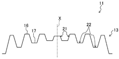
- FIG. 2 is a partial enlarged cross-sectional view of the central portion of the antireflection uneven structure 13 of the lens 11.
- the first flat portion 16 is formed at the top of the convex portion 21, and the second flat portion 17 is formed at the bottom of the concave portion 22.
- the top part of the convex part 21 and the bottom part of the concave part 22 have a sharp shape, and no flat part is formed.
- These first and second flat portions 16 and 17 constitute a flat surface.
- the first and second flat portions 16 and 17 are substantially orthogonal to the optical axis X. That is, the first and second flat portions 16 and 17 are substantially parallel to each other.
- the first and second flat portions 16 and 17 are substantially circular.
- the areas of the first and second flat portions 16 and 17 increase toward the center of the first optical surface 14, that is, as the height of the convex portion 21 decreases and the depth of the concave portion 22 decreases. growing. Note that the first and second flat portions 16 and 17 do not need to be strictly flat, and may be substantially flat.
- the portion of the first flat portion 16 that is farthest from the lower base surface in the optical axis direction is the top of the convex portion 21, and the second The portion of the flat portion 17 that is farthest from the upper base surface in the optical axis direction is the bottom of the concave portion 22, and the lower base surface, the upper base surface, the height of the convex portion 21, the period of the convex portion 21, and the depth of the concave portion 22. Now consider the period of the recess 22.
- the center of the first flat portion 16 is the top of the convex portion 21 and the second flat portion 17
- the center is the top of the recess 22.
- the lower base surface is a curved surface that passes through the bottom of the concave portion 22 that does not have the second flat portion 17 and passes through the center of the second flat portion 17 for the concave portion 22 that has the second flat portion 17.
- the height of the convex portion 21 is a dimension in the optical axis direction from the lower base surface to the center of the first flat portion 16.
- the period of the convex portion 21 is an interval between the centers of the first flat portions 16 of the adjacent convex portions 21 in a direction parallel to the plane orthogonal to the optical axis X.
- the reflection suppressing effect can be improved over the entire surface of the first optical surface 14.
- the convex portion 21 is high and the concave portion 22 is deep. That is, the portion where the convex portion 21 is low or the concave portion 22 is shallow has a smaller reflection suppressing effect than the portion where the convex portion 21 is high or the concave portion 22 is deep.
- the refractive index changes abruptly at the first and second flat portions 16 and 17, and in the first and second flat portions 16 and 17, Part of the incident light is reflected.
- the flat portions are provided in both the convex portion 21 and the concave portion 22, the light reflected by the first flat portion 16 and the light reflected by the second flat portion 15 interfere with each other and weaken each other. As a result, the reflected light as a whole of the first optical surface 14 is suppressed. That is, even if the reflection suppression effect is originally relatively small, the light reflection can be suppressed by using the light interference effect.
- the lens 11 is manufactured by molding using a lens mold.
- the lens mold has an inverted shape of SWS13.
- the lens 11 is molded by, for example, heat press molding.
- the lens 11 is molded by, for example, injection molding or UV molding.
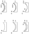
- FIG. 3 shows a process chart for producing the lens mold 37.
- a mold base material 31 is prepared. Then, as shown in FIG. 3A, a lens shape (a state before the SWS 13 is formed) is formed on the mold base material 31 by machining.
- a metal mask 32 is formed on the surface of the mold base material 31 formed in a lens shape.
- a method for forming the metal mask 32 a sputtering method, a vapor deposition method, or the like is preferable.
- a resist mask 33 is formed on the metal mask 32.
- a spin coating method or a spray coating method is preferable.
- a resist dot pattern 34 corresponding to the SWS 13 is formed from the resist mask 33.
- a method for forming the resist dot pattern 34 an electron beam drawing method, an interference exposure (hologram exposure) method, or the like is preferable.
- the hole diameter of the resist dot pattern 34 is preferably uniform over the entire surface.
- the resist dot pattern 34 is transferred to the metal mask 32 by dry etching. Thereby, a metal mask dot pattern 35 is formed.
- the metal mask dot pattern 35 may be formed by wet etching.
- the metal mask dot pattern 35 is transferred to the mold base material 31 by dry etching.
- a lens mold 37 in which the reverse shape 36 of the SWS 13 is formed on the surface of the mold base material 31 is completed.
- plasma (ions) generated in a dry etching apparatus concentrates on the protrusions or corners of the workpiece.
- plasma (ions) tends to concentrate on the end portion 38 of the mold base material 31. Therefore, the etching rate of the end portion 38 where the plasma is concentrated is high, and the etching rate of the central portion is low. As shown in FIG.
- the peripheral portion of the mold base 31 has a high etching speed because the etching rate is high, and the concave portion
- the convex portion is low and the concave portion is shallow.
- the etching time in the central part of the mold base material 31, the height of the convex part at the peripheral part of the mold base material 31 while leaving a flat part at the top part of the convex part and the bottom part of the concave part. And the depth of the recess can be maximized.
- the convex part is high and the concave part is deep in the peripheral part of the lens mold 37, and the convex part is gradually lowered and the concave part is gradually shallower toward the central part. .
- a flat portion is formed at the top of the convex portion at the center of the lens mold 37 and the bottom of the concave portion.
- the lens 11 includes the antireflection concavo-convex structure 13 in which a plurality of convex portions 21 and concave portions 22 are arranged and suppresses reflection of light having a wavelength longer than the period of the convex portions 21 and concave portions 22.
- the antireflection concavo-convex structure 13 includes a region where the convex portion 21 is relatively low and the concave portion 22 is relatively shallow, and a region where the convex portion 21 is relatively high and the concave portion 22 is relatively deep.
- the lens 11 is an optical element having at least one curved surface in which a plurality of structural units are regularly arranged and an antireflection concavo-convex structure that suppresses reflection of light having a wavelength longer than the period of the structural units is formed.
- the antireflection concavo-convex structure is a member having a region where the height of the structural unit is relatively small and a region where the height of the structural unit is relatively large, and the height of the structural unit.
- a substantially flat portion is formed on the upper and lower surfaces of the antireflection concavo-convex structure in a relatively small area.
- the reflection suppressing effect of the convex portion 21 and the concave portion 22 themselves is relatively small.
- the first flat portion 16 is formed at the top of the convex portion 21 and the second flat portion 17 is formed at the bottom of the concave portion 22, so that the reflected light at the first flat portion 16 and the reflected light at the second flat portion 17 are formed.
- the reflection suppression effect can be improved by the interference effect. As a result, even if the configuration is such that the convex portion 21 is relatively low and the concave portion 22 is relatively shallow, and the convex portion 21 is relatively high and the concave portion 22 is relatively deep.
- the suppression effect can be improved as a whole. Further, by making the convex portion 21 low and the concave portion 22 shallow, the antireflection concavo-convex structure 13 can be easily formed. That is, in the region where the ease of making the antireflection concavo-convex structure 13 is required, the first and second flat portions 16, 17 are formed at the top of the convex portion 21 and the bottom of the concave portion 22 by making the convex portion 21 low and the concave portion 22 shallow. By forming the structure, it is possible to prevent the deterioration of the antireflection effect while improving the ease of making the antireflection uneven structure 13. That is, it is possible to achieve both the ease of making the antireflection concavo-convex structure 13 and the antireflection effect, which could not be solved conventionally.
- the first and second flat portions 16 and 17 are larger as the convex portion 21 is lower or the concave portion 22 is shallower.
- the reflection suppressing effect of the convex portion 21 and the concave portion 22 itself becomes smaller.
- the reflection suppressing effect due to interference can be increased by increasing the first flat portion 16 as the convex portion 21 is lowered and increasing the second flat portion 17 as the concave portion 22 is shallow.
- the lens of this example corresponds to the lens 11 of the first embodiment.
- Example> As an example, the following lens was molded.
- Cyclic olefin polymers for example, ZEONEX (registered trademark) (manufactured by ZEON Corporation), ARTON (registered trademark) (manufactured by JSR Corporation), Apel (registered trademark) (manufactured by Mitsui Chemicals, Inc.)
- ZEONEX registered trademark
- ARTON registered trademark
- JSR Corporation manufactured by JSR Corporation
- Apel registered trademark
- silicon carbide (SiC) was prepared as the mold base material 31.
- a lens shape was formed on the die base material 31 by machining, tungsten silicide (WSi) was formed by sputtering, and then an electron beam resist (positive type) was applied by spin coating. Thereafter, a dot shape was drawn by electron beam drawing.
- a dot pattern was formed on the WSi mask by dry etching using argon gas. Thereafter, the SWS inversion shape was formed on the SiC surface of the mold base 31 by dry etching using a fluorocarbon-based gas.
- the lens mold 37 thus fabricated was subjected to a mold release treatment by being immersed in a fluorine-based mold release agent.
- a lens was injection molded using the lens mold 37 subjected to the mold release treatment.
- the lens 11 thus manufactured was a biconvex lens, and had an effective diameter of 16 mm and a lens thickness of 2.4 mm.
- the period of the convex portion 21 and the concave portion 22 was 250 nm over the entire surface of the first optical surface 14.
- the height of the convex portion 21 and the depth of the concave portion 22 are 350 nm at the peripheral portion of the lens and 210 nm at the central portion of the lens 11, and the height gradually decreases toward the central portion.
- first and second flat portions 16 and 17 are formed at the top of the convex portion 21 and the bottom of the concave portion 22 at the center of the lens 11, respectively.
- the outer diameter of the first flat portion 16 at the center of the lens 11 was about 60 nm.
- the areas of the first and second flat portions 16 and 17 became smaller toward the periphery of the lens 11.
- a lens in which the first and second flat portions 16 and 17 were not formed was molded. That is, in the lens according to the comparative example, the first flat portion 16 is not formed in the convex portion 21 in the lens according to the embodiment, and the second flat portion 17 is not formed in the concave portion 22. It was. Therefore, although the period of the convex part 21 and the recessed part 22 is the same in a comparative example and an Example, since the 1st and 2nd flat parts 16 and 17 are not formed, the direction of the comparative example is more convex part 21. High and the recess 22 is deep. Even so, in the lens according to the comparative example, the convex portion 21 is lower and the concave portion 22 is shallower in the central portion than in the peripheral portion. Other than that, the lens of the example and the lens of the comparative example are the same.
- FIG. 4 the result of having measured the reflectance of the lens surface about an Example and a comparative example is shown.
- an optical measuring device USPM-RU III manufactured by Olympus was used for the reflectance.
- BK7 which is a general optical glass
- the reflectance of Examples and Comparative Examples was measured.
- a measurement object (Example or Comparative Example) and a reference were set in the optical measurement apparatus, and the reflectance was measured by irradiating light of 400 to 700 nm.
- the graph of FIG. 7 shows the reflectance with respect to each wavelength of an Example and a comparative example.
- the horizontal axis in FIG. 7 is the wavelength
- the vertical axis is the reflectance.
- Graph (a), (b) is a graph which shows the reflectance of an Example. Specifically, the graph (a) shows a region in which the convex portion 21 is low and the concave portion 22 is shallow in the lens 11 according to the embodiment, and a flat portion is provided at the top of the convex portion 21 and the bottom of the concave portion 22. The reflectance at is shown.
- Graph (b) shows the reflectance in a region where the convex portion 21 is high and the concave portion 22 is deep in the lens 11 according to the example.
- the graph (c) shows the reflectance in the region (center portion of the lens) where the convex portion is low and the concave portion is shallow among the lenses according to the comparative example. In the comparative example, the flat portion is not provided.
- the reflectance with respect to visible light was less than about 1.4%.
- the reflectance with respect to light having a long wavelength among visible light is large.
- the height of the convex portion and the depth of the concave portion are about 210 nm, and the height of the convex portion and the depth of the concave portion for a component having a long wavelength in visible light. Is less than 0.4 times the wavelength. Therefore, the reflection of visible light cannot be sufficiently suppressed.
- the reflectance with respect to visible light is about 0.15% or less.
- a high antireflection effect is exhibited in a region where the convex portion is high and the concave portion is deep, but the antireflection effect is small in a region where the convex portion is low and the concave portion is shallow.
- the reflectance in the example, in the region where the convex portion 21 is high and the concave portion 22 is deep (peripheral portion of the lens), the reflectance can be suppressed to about 0.1% over the entire visible light region. . This is because the height of the convex portion 21 and the depth of the concave portion 22 are about 350 nm, and have a sufficient height and depth with respect to the wavelength of visible light. Further, in the region where the convex portion 21 is low and the concave portion 22 is deep (center portion of the lens), the reflectance can be suppressed to about 0.15% or less over the entire visible light region.
- the interference effect by the 1st flat part 16 of the convex part 21 and the 2nd flat part 17 of the recessed part 22 is exhibited, and the reflection suppression effect by it expressed.
- the effect of suppressing reflection can be made equal between a region where the convex portion 21 is high and the concave portion 22 is deep, and a region where the convex portion 21 is low and the concave portion 22 is shallow.
- a high antireflection effect can be exhibited.
- Embodiment 2 ⁇ Embodiment 2 >> Hereinafter, the second embodiment will be described with reference to the drawings.
- the lens according to the second embodiment is different from the lens according to the first embodiment in the shape of the SWS provided on the optical surface.
- the difference from the first embodiment will be mainly described.
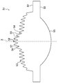
- FIG. 5 is a sectional view of the lens 41.
- the lens 41 has a first optical surface 44, a second optical surface 45, and an edge surface 42.
- a SWS 43 is formed on the first optical surface 44.
- the SWS 43 has a plurality of convex portions 48 and concave portions 49 arranged alternately. In the central portion of the first optical surface 44, the height of the convex portion 48 is relatively high and the depth of the concave portion 49 is relatively large. The height of the convex portion 48 and the depth of the concave portion 49 become lower and shallower toward the peripheral portion of the first optical surface 44.
- a first flat portion 46 is formed at the top of the convex portion 48, and a second flat portion 47 is formed at the bottom of the concave portion 49. Further, the areas of the first and second flat portions 46 and 47 become larger toward the peripheral portion of the first optical surface 44.
- the manufacturing method of the lens 41 is substantially the same as the manufacturing method of the lens 11 according to the first embodiment.
- the resist hole diameter in the peripheral portion is made larger than that in the central portion.
- the dose amount (exposure amount) of electron beam drawing may be changed.
- the first and second flat portions 46 and 47 are formed in the relatively low convex portion 48 and the shallow concave portion 49. That is, in the low convex portion 48 and the shallow concave portion 49, the reflection suppressing effect by the minute concave and convex portion is smaller than that in the high convex portion 48 and the deep concave portion 49, but it can be supplemented by the reflection suppressing effect by the interference effect. As a result, like the first embodiment, the reflectance with respect to visible light on the entire first optical surface 44 can be kept small.
- the peripheral portion of the first optical surface 44 is a portion where the inclination of the first optical surface 44 is the largest, and is a portion that is difficult to release during lens molding.
- a lens having a large inclination angle such as an objective lens capable of condensing blue light
- the amount of glass material deformation during molding increases toward the periphery, and the load on the lens mold increases toward the periphery. Therefore, in the peripheral part, the unevenness of the lens and the unevenness of the lens mold are tightly engaged with each other, making it difficult to release the mold.
- the amount of lens shrinkage in the cooling process during molding increases toward the periphery.
- the unevenness of the lens and the unevenness of the lens mold are closely meshed with each other at the periphery, and it becomes difficult to release the mold.
- the surface area is increased, which makes it more difficult to release.
- the above-mentioned problem is solved by lowering the convex portion 48 and shallowing the concave portion 49 in the peripheral portion and forming the first and second flat portions 46 and 47 in addition thereto. Can be formed easily. That is, it is possible to achieve both the ease of manufacturing the lens and the improvement of the reflection suppression effect.
- Embodiment 3 The third embodiment will be described below with reference to the drawings.
- the lens according to the third embodiment is different from the lenses according to the first and second embodiments in the shape of SWS formed on the optical surface.
- the difference from the first and second embodiments will be mainly described.
- FIG. 6 is a cross-sectional view of the lens 51.
- the lens 51 has a first optical surface 54, a second optical surface 55, and an edge surface 52.
- a SWS 53 is formed on the first optical surface 54.
- the SWS 53 has a plurality of convex portions 58 and concave portions 59 that are alternately arranged.
- the height of the convex portion 58 and the depth of the concave portion 59 are not uniform over the first optical surface 54, and differ depending on the location.
- the height of the convex portion 58 and the depth of the concave portion 59 do not change monotonously according to the radial position of the first optical surface 54, but increase or decrease.
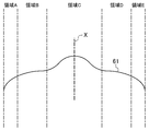
- the first optical surface 54 has a base surface 61 as shown in FIG.
- the base surface 61 has regions A to E.
- Regions A and E are regions located on the outermost periphery of the base surface 61 and are regions having a large inclination angle with respect to the optical axis X (hereinafter simply referred to as “inclination angle”).
- the region C is a region located in the central portion of the base surface 61, and includes a portion where the central inclination angle is gentle and a portion where the peripheral inclination angle is steep.
- the region B is a region located between the region A and the region C, and includes a substantially horizontal portion with a gentle inclination angle.
- the region D is a region located between the region E and the region C, and includes a substantially horizontal portion with a gentle inclination angle.
- the reflection suppressing effect can be improved by the interference effect.
- the reflectance with respect to visible light can be kept small over the entire first optical surface 54.
- regions A and E it is possible to make the structure easy to release during molding without deteriorating the reflection suppressing effect.
- regions B and D the ease of making can be improved without deteriorating the reflection suppression effect.
- regions B and D a high antireflection effect can be exhibited by increasing the convex portion 59 and deepening the concave portion 59. .
- the lens mold for molding such SWS 53 can be manufactured by controlling the hole diameter when forming the resist dot pattern 34 as in the second embodiment.
- the height of the convex portion and the depth of the concave portion are changed in accordance with the lens shape such as the tilt angle and the position of the lens such as the central portion and the peripheral portion.
- molding especially mold release
- the reflection suppressing effect can be improved by providing a flat portion at the top of the convex portion and the bottom of the concave portion. That is, for various reasons, the convex portion may be lowered and the concave portion may be shallow, but even in such a case, it is possible to prevent the reflection suppression effect from deteriorating. As a result, a lens having a high reflection suppression effect can be realized over the entire optical surface.
- the lens manufacturing method and lens mold manufacturing method are not limited to the above-described embodiment.
- the mold base material may be any material that has high strength and is easily finely processed by etching.
- quartz SiO2, silicon carbide (SiC), silicon (Si), glassy carbon (C), carbide (WC), or the like may be used.
- metal mask material Cr, Ta, WSi, Ni, W, etc. may be used.
- the electron beam drawing method is used for manufacturing the lens mold, but the present invention is not limited to this.
- Lithography such as an interference exposure (hologram exposure) method or X-ray lithography may be used.
- the mask may be formed by nanoimprint or particle arrangement.
- the configuration of the lens is not limited to the above embodiment.
- a convex lens has been described, but a concave lens may be used.
- the optical member on which the SWS is formed is not limited to a lens. You may apply SWS of the said structure to the surface of a display, the internal peripheral surface of a lens-barrel, a prism. That is, the base surface on which the SWS 13 is formed may be a flat surface.
- the SWS is provided only on the first optical surface, but is not limited thereto.
- the SWS may be provided on both the first optical surface and the second optical surface, or may be provided only on the second optical surface.
- the convex portion has a conical shape and the concave portion has a mortar shape.
- the convex portion may be a pyramid such as a quadrangular pyramid or a triangular pyramid, and the concave portion may be an inverted shape thereof.
- a convex part and a recessed part are not restricted to a cone shape and its inversion shape, Arbitrary shapes can be employ
- the convex portion may be a linear convex portion extending in the circumferential direction around the optical axis X
- the concave portion may be a linear concave portion extending in the circumferential direction around the optical axis X.
- the flat part formed at the top of the convex part and the bottom part of the concave part has a larger radial width around the optical axis X as the convex part becomes lower and the concave part becomes shallower.
- the optical member according to the present invention has a reflection suppressing effect and high environmental resistance, and is useful as a lens barrel, an optical element represented by a lens, and the like.
- various optical systems such as a high-quality imaging optical system, objective optical system, scanning optical system, and pickup optical system, lens barrel unit, optical pickup unit, and imaging unit
- An optical unit, an imaging device, an optical pickup device, an optical scanning device, and the like can be realized.
Landscapes
- Physics & Mathematics (AREA)
- General Physics & Mathematics (AREA)
- Optics & Photonics (AREA)
- Surface Treatment Of Optical Elements (AREA)
Abstract
Une lentille (11) comprend des saillies (21) et des évidements (22) situés sur celle-ci. Elle comporte une structure de surface irrégulière de prévention de la réflexion (13) qui réduit la réflexion d'une lumière dont une longueur d'onde est supérieure ou égale au pas des saillies (21) et des évidements (22). La structure de surface irrégulière de prévention de la réflexion (13) comporte une région dans laquelle les saillies (21) sont relativement basses et les évidements (22) sont relativement peu profonds et une région dans laquelle les saillies (21) sont relativement hautes et les évidements (22) sont relativement profonds. Dans la région dans laquelle les saillies (21) sont relativement basses et les évidements (22) sont relativement peu profonds, des première et seconde surfaces plates (16, 17) sont respectivement formées sur le dessus de chaque saillie (21) et au fond de chaque évidement (22).
Priority Applications (2)
| Application Number | Priority Date | Filing Date | Title |
|---|---|---|---|
| JP2012527925A JP5352010B2 (ja) | 2011-02-22 | 2012-02-20 | 光学部材 |
| US13/765,111 US9268067B2 (en) | 2011-02-22 | 2013-02-12 | Optical component having antireflection structure |
Applications Claiming Priority (2)
| Application Number | Priority Date | Filing Date | Title |
|---|---|---|---|
| JP2011035663 | 2011-02-22 | ||
| JP2011-035663 | 2011-02-22 |
Related Child Applications (1)
| Application Number | Title | Priority Date | Filing Date |
|---|---|---|---|
| US13/765,111 Continuation US9268067B2 (en) | 2011-02-22 | 2013-02-12 | Optical component having antireflection structure |
Publications (1)
| Publication Number | Publication Date |
|---|---|
| WO2012114714A1 true WO2012114714A1 (fr) | 2012-08-30 |
Family
ID=46720508
Family Applications (1)
| Application Number | Title | Priority Date | Filing Date |
|---|---|---|---|
| PCT/JP2012/001109 Ceased WO2012114714A1 (fr) | 2011-02-22 | 2012-02-20 | Élément optique |
Country Status (3)
| Country | Link |
|---|---|
| US (1) | US9268067B2 (fr) |
| JP (1) | JP5352010B2 (fr) |
| WO (1) | WO2012114714A1 (fr) |
Cited By (9)
| Publication number | Priority date | Publication date | Assignee | Title |
|---|---|---|---|---|
| WO2013150744A1 (fr) * | 2012-04-04 | 2013-10-10 | パナソニック株式会社 | Élément optique, dispositif d'imagerie équipé de celui-ci, et procédé de fabrication de l'élément optique |
| WO2013150742A1 (fr) * | 2012-04-04 | 2013-10-10 | パナソニック株式会社 | Élément optique, dispositif d'imagerie équipé de celui-ci, et procédé de fabrication de l'élément optique |
| JP2014102311A (ja) * | 2012-11-19 | 2014-06-05 | Seiko Epson Corp | マイクロレンズアレイ基板、マイクロレンズアレイ基板の製造方法、電気光学装置、電子機器 |
| WO2014112593A1 (fr) * | 2013-01-17 | 2014-07-24 | コニカミノルタ株式会社 | Procédé de production d'élément optique et procédé de production de structure antireflet |
| JP2018527629A (ja) * | 2015-08-14 | 2018-09-20 | マツクス−プランク−ゲゼルシヤフト ツール フエルデルング デル ヴイツセンシヤフテン エー フアウMAX−PLANCK−GESELLSCHAFT ZUR FOeRDERUNG DER WISSENSCHAFTEN E.V. | 単一基板上に複数のナノ構造勾配を含むナノ構造基板の製造 |
| JP2019204051A (ja) * | 2018-05-25 | 2019-11-28 | 国立研究開発法人産業技術総合研究所 | 光接続部品、及び光接続部品の製造方法 |
| JP2020521530A (ja) * | 2017-06-01 | 2020-07-27 | カール・ツアイス・メディテック・アーゲー | 回折格子構造を有する人工水晶体及び人工水晶体を製造する方法 |
| US11583391B2 (en) | 2017-06-01 | 2023-02-21 | Carl Zeiss Meditec Ag | Artificial eye lens with laser-generated birefringent structure and method for producing an artificial eye lens |
| WO2023189459A1 (fr) * | 2022-03-28 | 2023-10-05 | ソニーセミコンダクタソリューションズ株式会社 | Dispositif de photodétection, procédé de fabrication de dispositif de photodétection et appareil électronique |
Families Citing this family (2)
| Publication number | Priority date | Publication date | Assignee | Title |
|---|---|---|---|---|
| JP2015220313A (ja) | 2014-05-16 | 2015-12-07 | ソニー株式会社 | 固体撮像装置およびその製造方法、並びに電子機器 |
| KR101746076B1 (ko) | 2015-04-20 | 2017-06-12 | 주식회사 이엘피 | 미세 형상 구조체를 갖는 렌즈 및 그 렌즈 제조 방법 |
Citations (3)
| Publication number | Priority date | Publication date | Assignee | Title |
|---|---|---|---|---|
| JP2005157325A (ja) * | 2003-10-27 | 2005-06-16 | Matsushita Electric Ind Co Ltd | 光量分布制御素子、並びにそれを用いた光学機器 |
| WO2007018149A1 (fr) * | 2005-08-08 | 2007-02-15 | Matsushita Electric Industrial Co., Ltd. | Système optique d’imagerie |
| JP2007127855A (ja) * | 2005-11-04 | 2007-05-24 | Konica Minolta Holdings Inc | 光学素子 |
Family Cites Families (10)
| Publication number | Priority date | Publication date | Assignee | Title |
|---|---|---|---|---|
| JP2002267815A (ja) | 2001-03-08 | 2002-09-18 | Dainippon Printing Co Ltd | 反射防止性成形品およびその製造方法 |
| CN100501458C (zh) | 2003-10-27 | 2009-06-17 | 松下电器产业株式会社 | 光量分布控制元件及使用该元件的光学装置 |
| WO2005092588A1 (fr) | 2004-03-25 | 2005-10-06 | Sanyo Electric Co., Ltd. | Procede de fabrication de moule de metal a surface incurvee ayant une fine structure irreguliere et procede de fabrication d'element optique utilisant ledit moule de metal |
| JP2005283814A (ja) * | 2004-03-29 | 2005-10-13 | Sanyo Electric Co Ltd | 反射防止処理を施した光学素子及びその金型並びに金型の製造方法 |
| WO2007142186A1 (fr) | 2006-06-06 | 2007-12-13 | Panasonic Corporation | Élément optique |
| JP5383188B2 (ja) | 2006-06-21 | 2014-01-08 | パナソニック株式会社 | レンズ鏡筒 |
| WO2008001662A1 (fr) * | 2006-06-30 | 2008-01-03 | Panasonic Corporation | Élément optique et dispositif optique le comprenant |
| JP4933173B2 (ja) | 2006-07-03 | 2012-05-16 | 株式会社リコー | 成形品、成形型、光学素子、光学装置、光走査装置、画像表示装置、光ピックアップ装置 |
| JP4539657B2 (ja) * | 2007-01-18 | 2010-09-08 | ソニー株式会社 | 反射防止用光学素子 |
| JP2009198628A (ja) | 2008-02-20 | 2009-09-03 | Nissan Motor Co Ltd | 反射防止構造及び反射防止成形体 |
-
2012
- 2012-02-20 JP JP2012527925A patent/JP5352010B2/ja not_active Expired - Fee Related
- 2012-02-20 WO PCT/JP2012/001109 patent/WO2012114714A1/fr not_active Ceased
-
2013
- 2013-02-12 US US13/765,111 patent/US9268067B2/en not_active Expired - Fee Related
Patent Citations (3)
| Publication number | Priority date | Publication date | Assignee | Title |
|---|---|---|---|---|
| JP2005157325A (ja) * | 2003-10-27 | 2005-06-16 | Matsushita Electric Ind Co Ltd | 光量分布制御素子、並びにそれを用いた光学機器 |
| WO2007018149A1 (fr) * | 2005-08-08 | 2007-02-15 | Matsushita Electric Industrial Co., Ltd. | Système optique d’imagerie |
| JP2007127855A (ja) * | 2005-11-04 | 2007-05-24 | Konica Minolta Holdings Inc | 光学素子 |
Cited By (16)
| Publication number | Priority date | Publication date | Assignee | Title |
|---|---|---|---|---|
| US9285509B2 (en) | 2012-04-04 | 2016-03-15 | Panasonic Intellectual Property Management Co., Ltd. | Optical element, imaging apparatus including the element, and method of manufacturing the optical element |
| WO2013150742A1 (fr) * | 2012-04-04 | 2013-10-10 | パナソニック株式会社 | Élément optique, dispositif d'imagerie équipé de celui-ci, et procédé de fabrication de l'élément optique |
| JP5555817B2 (ja) * | 2012-04-04 | 2014-07-23 | パナソニック株式会社 | 光学素子、それを備えた撮像装置及び光学素子の製造方法 |
| JP5555816B2 (ja) * | 2012-04-04 | 2014-07-23 | パナソニック株式会社 | 光学素子、それを備えた撮像装置及び光学素子の製造方法 |
| WO2013150744A1 (fr) * | 2012-04-04 | 2013-10-10 | パナソニック株式会社 | Élément optique, dispositif d'imagerie équipé de celui-ci, et procédé de fabrication de l'élément optique |
| US9279916B2 (en) | 2012-04-04 | 2016-03-08 | Panasonic Intellectual Property Management Co., Ltd. | Optical element, imaging apparatus including the element, and method of manufacturing the optical element |
| JP2014102311A (ja) * | 2012-11-19 | 2014-06-05 | Seiko Epson Corp | マイクロレンズアレイ基板、マイクロレンズアレイ基板の製造方法、電気光学装置、電子機器 |
| JPWO2014112593A1 (ja) * | 2013-01-17 | 2017-01-19 | コニカミノルタ株式会社 | 光学素子の製造方法及び反射防止構造体の作製方法 |
| WO2014112593A1 (fr) * | 2013-01-17 | 2014-07-24 | コニカミノルタ株式会社 | Procédé de production d'élément optique et procédé de production de structure antireflet |
| JP2018527629A (ja) * | 2015-08-14 | 2018-09-20 | マツクス−プランク−ゲゼルシヤフト ツール フエルデルング デル ヴイツセンシヤフテン エー フアウMAX−PLANCK−GESELLSCHAFT ZUR FOeRDERUNG DER WISSENSCHAFTEN E.V. | 単一基板上に複数のナノ構造勾配を含むナノ構造基板の製造 |
| JP2020521530A (ja) * | 2017-06-01 | 2020-07-27 | カール・ツアイス・メディテック・アーゲー | 回折格子構造を有する人工水晶体及び人工水晶体を製造する方法 |
| JP7152421B2 (ja) | 2017-06-01 | 2022-10-12 | カール・ツアイス・メディテック・アーゲー | 回折格子構造を有する人工水晶体及び人工水晶体を製造する方法 |
| US11583391B2 (en) | 2017-06-01 | 2023-02-21 | Carl Zeiss Meditec Ag | Artificial eye lens with laser-generated birefringent structure and method for producing an artificial eye lens |
| JP2019204051A (ja) * | 2018-05-25 | 2019-11-28 | 国立研究開発法人産業技術総合研究所 | 光接続部品、及び光接続部品の製造方法 |
| JP7258327B2 (ja) | 2018-05-25 | 2023-04-17 | 国立研究開発法人産業技術総合研究所 | 光接続部品、及び光接続部品の製造方法 |
| WO2023189459A1 (fr) * | 2022-03-28 | 2023-10-05 | ソニーセミコンダクタソリューションズ株式会社 | Dispositif de photodétection, procédé de fabrication de dispositif de photodétection et appareil électronique |
Also Published As
| Publication number | Publication date |
|---|---|
| JPWO2012114714A1 (ja) | 2014-07-07 |
| JP5352010B2 (ja) | 2013-11-27 |
| US9268067B2 (en) | 2016-02-23 |
| US20130148206A1 (en) | 2013-06-13 |
Similar Documents
| Publication | Publication Date | Title |
|---|---|---|
| JP5352010B2 (ja) | 光学部材 | |
| JP5525656B2 (ja) | 光学素子の製造方法 | |
| JP5587672B2 (ja) | マスクブランク用基板の製造方法、インプリントモールド用マスクブランクの製造方法、及びインプリントモールドの製造方法 | |
| JP4916597B2 (ja) | 型および型の製造方法ならびに反射防止膜 | |
| JP6470176B2 (ja) | 多層反射膜付き基板、euvリソグラフィー用反射型マスクブランク、euvリソグラフィー用反射型マスク及びその製造方法、並びに半導体装置の製造方法 | |
| JP5521655B2 (ja) | 反射型スクリーン、投影システム、フロントプロジェクションテレビ及び反射型スクリーンの製造方法 | |
| JP5615971B2 (ja) | 型の製造方法 | |
| JPWO2005109042A1 (ja) | 光学素子及びその製造方法 | |
| JP4739729B2 (ja) | 反射防止構造体を備えた部材の製造方法 | |
| WO2013150742A1 (fr) | Élément optique, dispositif d'imagerie équipé de celui-ci, et procédé de fabrication de l'élément optique | |
| TW202143330A (zh) | 平坦化設備、平坦化程序及製造物品的方法 | |
| JPWO2016084745A1 (ja) | 型および型の製造方法ならびに反射防止膜 | |
| WO2020031945A1 (fr) | Élément optique à structure antireflet, son procédé de production, procédé de production de moule de production et dispositif d'imagerie | |
| JP2007193249A (ja) | 成形部品の製造方法 | |
| JP4457589B2 (ja) | 透過型光学素子を有する光学装置 | |
| JP2013109228A (ja) | 光学部材 | |
| KR101962034B1 (ko) | 무반사 나노패턴을 포함하는 광대역 대물렌즈 및 이의 제조방법 | |
| JP2014186305A (ja) | 光学部材 | |
| JP5414945B1 (ja) | 光学素子及びそれを備えた撮像装置 | |
| JP2023039111A (ja) | 回折光学素子、その製造方法および型の製造方法 | |
| JP5935281B2 (ja) | 型、型の製造方法、および、型を用いた反射防止フィルムの製造方法 | |
| JP5622118B2 (ja) | 反射防止フィルム、反射防止フィルムの作製に用いられる型、および、型の製造方法 | |
| JP2016004096A (ja) | 光学素子及びそれを備えた撮像装置 | |
| KR20130068549A (ko) | 비반사 유리 및 그 제조방법 | |
| JP7192409B2 (ja) | インプリントモールド用基板及びインプリントモールド、並びにそれらの製造方法 |
Legal Events
| Date | Code | Title | Description |
|---|---|---|---|
| WWE | Wipo information: entry into national phase |
Ref document number: 2012527925 Country of ref document: JP |
|
| 121 | Ep: the epo has been informed by wipo that ep was designated in this application |
Ref document number: 12749102 Country of ref document: EP Kind code of ref document: A1 |
|
| NENP | Non-entry into the national phase |
Ref country code: DE |
|
| 122 | Ep: pct application non-entry in european phase |
Ref document number: 12749102 Country of ref document: EP Kind code of ref document: A1 |