WO2012114754A1 - Dispositif électronique - Google Patents
Dispositif électronique Download PDFInfo
- Publication number
- WO2012114754A1 WO2012114754A1 PCT/JP2012/001236 JP2012001236W WO2012114754A1 WO 2012114754 A1 WO2012114754 A1 WO 2012114754A1 JP 2012001236 W JP2012001236 W JP 2012001236W WO 2012114754 A1 WO2012114754 A1 WO 2012114754A1
- Authority
- WO
- WIPO (PCT)
- Prior art keywords
- panel
- touch panel
- elastic member
- piezoelectric element
- vibration
- Prior art date
- Legal status (The legal status is an assumption and is not a legal conclusion. Google has not performed a legal analysis and makes no representation as to the accuracy of the status listed.)
- Ceased
Links
Images




Classifications
-
- G—PHYSICS
- G06—COMPUTING OR CALCULATING; COUNTING
- G06F—ELECTRIC DIGITAL DATA PROCESSING
- G06F3/00—Input arrangements for transferring data to be processed into a form capable of being handled by the computer; Output arrangements for transferring data from processing unit to output unit, e.g. interface arrangements
- G06F3/01—Input arrangements or combined input and output arrangements for interaction between user and computer
- G06F3/016—Input arrangements with force or tactile feedback as computer generated output to the user
-
- G—PHYSICS
- G06—COMPUTING OR CALCULATING; COUNTING
- G06F—ELECTRIC DIGITAL DATA PROCESSING
- G06F1/00—Details not covered by groups G06F3/00 - G06F13/00 and G06F21/00
- G06F1/16—Constructional details or arrangements
- G06F1/1613—Constructional details or arrangements for portable computers
- G06F1/1626—Constructional details or arrangements for portable computers with a single-body enclosure integrating a flat display, e.g. Personal Digital Assistants [PDAs]
-
- G—PHYSICS
- G06—COMPUTING OR CALCULATING; COUNTING
- G06F—ELECTRIC DIGITAL DATA PROCESSING
- G06F1/00—Details not covered by groups G06F3/00 - G06F13/00 and G06F21/00
- G06F1/16—Constructional details or arrangements
- G06F1/1613—Constructional details or arrangements for portable computers
- G06F1/1633—Constructional details or arrangements of portable computers not specific to the type of enclosures covered by groups G06F1/1615 - G06F1/1626
- G06F1/1637—Details related to the display arrangement, including those related to the mounting of the display in the housing
- G06F1/1643—Details related to the display arrangement, including those related to the mounting of the display in the housing the display being associated to a digitizer, e.g. laptops that can be used as penpads
-
- G—PHYSICS
- G06—COMPUTING OR CALCULATING; COUNTING
- G06F—ELECTRIC DIGITAL DATA PROCESSING
- G06F1/00—Details not covered by groups G06F3/00 - G06F13/00 and G06F21/00
- G06F1/16—Constructional details or arrangements
- G06F1/1613—Constructional details or arrangements for portable computers
- G06F1/1633—Constructional details or arrangements of portable computers not specific to the type of enclosures covered by groups G06F1/1615 - G06F1/1626
- G06F1/1656—Details related to functional adaptations of the enclosure, e.g. to provide protection against EMI, shock, water, or to host detachable peripherals like a mouse or removable expansions units like PCMCIA cards, or to provide access to internal components for maintenance or to removable storage supports like CDs or DVDs, or to mechanically mount accessories
-
- H—ELECTRICITY
- H04—ELECTRIC COMMUNICATION TECHNIQUE
- H04M—TELEPHONIC COMMUNICATION
- H04M1/00—Substation equipment, e.g. for use by subscribers
- H04M1/02—Constructional features of telephone sets
- H04M1/0202—Portable telephone sets, e.g. cordless phones, mobile phones or bar type handsets
- H04M1/026—Details of the structure or mounting of specific components
- H04M1/0266—Details of the structure or mounting of specific components for a display module assembly
Definitions
- the present invention relates to an electronic device that includes a panel that forms an appearance and vibrates the panel.
- touch panels and touch pads are widely used as input devices for electronic devices.
- a device that feeds back a feeling of operation to an operator's fingertip by vibrating the touch panel or the touch pad is proposed (for example, see Patent Document 1).
- the above-mentioned problem is a problem that is expected to occur in common in an electronic device that includes a panel that configures the appearance and vibrates the panel.
- a predetermined electrical signal (audio signal) is applied to vibrate the panel, and vibration is applied to a part of the user's body (for example, the cartilage of the outer ear) that contacts the panel.
- an electronic device that vibrates the panel there is an electronic device having a function of removing water droplets and dirt attached to the panel due to the vibration of the panel.
- the present invention A panel, A vibrating part for vibrating the panel;
- An electronic device comprising a casing covering an outer edge of the upper surface of the panel, Provide a collar extending inward over the entire circumference of the top of the housing, A first elastic member is disposed between the upper surface outer edge and the flange portion over the entire periphery of the upper surface outer edge of the panel,
- the electronic device is characterized in that a second elastic member is disposed between the bottom surface outer edge and a support member positioned below the entire periphery of the bottom surface outer edge of the panel.
- an electronic device that includes a panel that configures the appearance and vibrates the panel can be made difficult to inhibit the vibration of the panel, and can be improved in dust resistance and waterproofness.
- FIG. 5B is a cross-sectional view taken along the line bb in FIG. It is sectional drawing which shows the modification of the electronic device which concerns on the 2nd Embodiment of this invention.
- FIG. 1 is a perspective view of an electronic apparatus according to this embodiment.
- the electronic apparatus 1 includes an upper casing 10a, a lower casing 10b, and a touch panel 20 in appearance.
- the “touch panel” means a member disposed on the front surface of the display unit that can be an LCD or the like, that is, a member provided separately from the display unit.
- the upper casing 10a and the lower casing 10b constitute the casing 10 by combining them together.
- an appropriate waterproof and dustproof measure can be taken, for example, by using a sealed structure with rubber packing.
- the upper housing 10a and the lower housing 10b are preferably made of a material that can withstand a certain degree of impact, such as a resin case. In the following description, detailed description of the combined structure of the upper housing 10a and the lower housing 10b is omitted.
- the touch panel 20 is usually disposed on the front surface of a display unit (not shown), and touching an object displayed on the display unit with an operator's finger, a stylus pen or the like (hereinafter simply referred to as “contact object”), Detection is performed on the touch surface of the corresponding touch panel 20.
- the touch panel 20 detects the position of contact of the contact object with respect to the touch surface, and notifies the detected position of the contact to a control unit (not shown).
- the touch panel 20 may be a touch panel configured by a known system such as a resistive film system, a capacitance system, and an optical system.
- a contact thing it is not essential that a contact thing touches the touch panel 20 physically.
- the touch panel 20 is optical, the touch panel 20 detects a position where the infrared light on the touch panel 20 is blocked by the contact object, and thus it is not necessary for the contact object to touch the touch panel 20.
- the display unit described above displays an object such as a push button switch (push button switch) such as a key as an image.
- This object is an image that suggests to the operator an area to be touched on the touch surface of the touch panel 20.
- the push button switch is a button, key, or the like (hereinafter, simply referred to as “key, etc.”) used by an operator for input operation.
- This display unit is configured using, for example, a liquid crystal display panel (LCD), an organic EL display panel, or the like.
- FIG. 2 shows a state in which the electronic device 1 shown in FIG. 1 is disassembled into an upper housing 10a, a lower housing 10b, a touch panel 20, a first elastic member 30, a second elastic member 40, and a vibration unit 50. It is a disassembled perspective view.
- the touch panel 20 is inserted between the upper casing 10a and the lower casing 10b, and the upper outer edge of the touch panel 20 is covered with the upper casing 10a.
- the outer edge of the upper surface of the touch panel 20 refers to an edge area of the touch panel on the upper surface of the touch panel 20, and preferably refers to an area having a width of about 1.0 to 5.0 mm.
- the upper casing 10a is provided with a flange 10a-1 extending inward at the top.
- a frame-shaped first elastic member 30 is disposed between the flange portion 10 a-1 and the outer periphery of the upper surface of the touch panel 20 over the entire outer periphery of the upper surface of the touch panel 20. Details of the first elastic member 30 will be described later.
- a frame-shaped second elastic member 40 which will be described in detail later, is disposed over the entire outer periphery of the bottom surface of the touch panel 20.
- the bottom edge of the touch panel 20 refers to the edge area of the touch panel on the bottom surface of the touch panel 20, and preferably a region having a width of about 1.0 to 5.0 mm as in the case of the first elastic member 30.
- the vibrating section 50 is disposed near the upper and lower edges (the back side and the near side in the drawing).
- the vibration part 50 can be comprised, for example with a piezoelectric element.
- the arrangement of the vibration unit 50 is not limited to the vicinity of the upper and lower edges of the touch panel 20, and may be arranged, for example, near the left and right edges of the touch panel 20.
- the vibration part 50 presents a tactile sensation to the contact object that is in contact with the touch surface by generating vibration according to a predetermined vibration pattern.
- the vibration unit 50 induces vibration based on, for example, a drive signal supplied from a control unit (not shown).
- a display unit 60 such as an LCD is disposed in a recess formed in the lower housing 10b.
- a substrate (not shown) is installed on the bottom surface of the display unit 60.
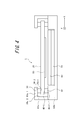
- FIG. 3 is a cross-sectional view taken along line AA of the electronic device 1 in FIG.
- FIG. 3 reference numerals for explaining the configuration on the right side of the figure are omitted.
- the touch panel 20 has a first elastic so as to close a gap between the outer edge of the upper surface and the flange portion 10a-1 of the upper casing 10a.
- the member 30 is disposed, and the second elastic member 40 is disposed between the outer edge of the bottom surface of the touch panel 20 and the lower housing 10b and is installed in the electronic apparatus 1.
- the first elastic member 30 can block out, that is, seal the outside air into the device between the touch panel 20 and the flange portion 10a-1 of the upper housing 10a, Dust protection is realized.
- the first elastic member 30 is made of a material having sufficient waterproofness and dustproofness and appropriate elasticity, and for example, it is preferable to use silicon rubber.
- the touch panel 20 since the upper surface outer edge and the bottom surface outer edge of the touch panel 20 can be elastically supported by the first elastic member 30 and the second elastic member 40, respectively, the touch panel 20 includes the first elastic member 30 and the first elastic member 30. Since the second elastic member 40 can be curved and vibrated while being deformed, the bending vibration is hardly attenuated.
- the second elastic member 40 is used for supporting the touch panel, but in the present embodiment, the same material as the first elastic member 30 is used, and the first elastic member 30 is turned upside down. It has a different shape. Accordingly, the vibration node when the touch panel 20 undergoes bending vibration can be easily held at the center of the flange portion 10a-1 and the lower housing 10b of the upper housing 10a. Can be prevented.
- the second elastic member 40 does not necessarily have to be continuously arranged over the entire outer periphery of the bottom surface of the touch panel 20 and may be intermittent. Moreover, when arrange
- the first elastic member 30 has a substantially inverted convex shape in a cross section orthogonal to the longitudinal direction
- the second elastic member 40 has a substantially convex character in a cross section orthogonal to the longitudinal direction. It has a shape. Therefore, when the touch panel 20 is curved and vibrated, the reaction force from the first elastic member 30 and the second elastic member 40 can be reduced, and the touch panel 20 can move to the first elastic member 30 and the second elastic member 40. The risk of collision can be reduced. As a result, the attenuation of the bending vibration of the touch panel 20 can be further reduced.
- the fulcrum of vibration of the touch panel 20 is placed on the line. Can be located. That is, the vibration in the lateral direction of the touch panel 20 can be reduced, and the vibration attenuation of the touch panel 20 can be further reduced.
- the above-described cross-sectional shapes of the first elastic member 30 and the second elastic member 40 can obtain the same effect as described above as long as the cross-sectional shape is tapered toward the touch panel 20 side. It is not essential to have a shape.
- the cross-sectional shapes of the first elastic member 30 and the second elastic member 40 may be rectangular.
- the tapered shape is not limited to a substantially convex shape, and may be a triangular shape or a semicircular shape.
- the first elastic member 30 is a touch panel at the contact portion 30-1 to the touch panel 20 and the contact portion 30-2 to the flange portion 10a-1 of the upper housing 10a.
- it is fixed to 20 and the flange portion 10a-1 by a double-sided tape or an adhesive.
- the second elastic member 40 is also in the same manner as the first elastic member 30, and the contact portion 40-1 to the touch panel 20 and the contact portion 40- to the lower housing 10b. 2, each is fixed to the touch panel 20 and the lower housing 10b with, for example, a double-sided tape or an adhesive. Accordingly, it is possible to reduce the displacement of the touch panel 20 in the XY directions when the touch panel 20 vibrates.
- the first elastic member 30 has a contact portion 30-2, and the second elastic member 40 has a contact portion 40-2 with respect to the flange portion 10a-1 and the lower housing 10b of the upper housing 10a, respectively.
- first elastic member 30 and the second elastic member 40 are not necessarily fixed to the flange portion 10a-1, the touch panel 20, and the lower housing 10b as described above.
- the material and shape of the second elastic member 40 it is possible to omit all of the above-described fixing, or to omit only the fixing of the contact portions 30-1 and 40-1. If there is a concern about the positional displacement of the touch panel 20, it is also effective to install a cushion material between the side wall 10a-2 of the upper housing 10a and the touch panel 20.
- the lower housing 10b corresponds to a support member.
- the support member is not limited to the lower housing 10b.
- a support portion that extends to the bottom surface of the touch panel 20 may be extended to the upper housing 10a, and this support portion may be used as the support member.
- the width of the concave portion of the lower housing 10b and the display portion 60 can be expanded to use the display portion 60 as a support member, or the width of the concave portion of the lower housing 10b and the substrate 70 can be expanded.
- the substrate 70 can be used as a support member.
- the upper housing 10a may be a two-part structure of a bezel (frame-like member) disposed above the outer edge of the upper surface of the touch panel 20 and the upper housing body, for example.
- the upper housing has such a two-part structure, the same effect as described above can be obtained by arranging the first elastic member 30 between the bezel and the touch panel 20.
- the first elastic member and the second elastic member are used to reduce attenuation of the bending vibration of the touch panel by the vibration unit, while waterproofing the electronic device.
- the dustproof effect can be improved.
- the present invention is not limited to the above embodiment, and many variations or modifications are possible.
- positioned at the bottom face of a touch panel, and a touch panel detects an operator's contact was demonstrated.
- the present invention is not limited to such an embodiment.
- an embodiment in which an object is directly printed with ink or the like on the touch surface of the touch panel without having a display unit is also applicable. .
- the touch panel has been described assuming a member such as a so-called touch sensor.
- the touch panel used in the electronic device according to the present invention may be any as long as it can be touched by a contact object such as an operator's finger or a stylus pen.
- the touch panel used in the electronic device according to the present invention may be a member such as a simple “panel” that does not detect the position of contact of the contact object with the touch surface (that is, does not have a sensing function).
- the electronic device having such a configuration for example, it is possible to determine that contact with the touch panel has been made based on the pressure detected by the pressure detection unit by further providing a pressure detection unit that detects pressure on the touch panel. it can.
- a touch panel is used to detect contact with the touch surface of the touch panel.
- the touch detection unit detects a press on the touch panel and that the touch is made on the touch panel based on the press.
- the above-described press detection unit detects a press on the touch surface of the touch panel.
- a strain gauge sensor or a piezoelectric that changes physical or electrical characteristics (strain, resistance, voltage, etc.) according to the press.
- An arbitrary number of elements can be used.
- the vibration unit is a piezoelectric element
- the piezoelectric element can also be used as a press detection unit.
- the piezoelectric element of the pressure detection unit is a load (force) magnitude (or magnitude of the load (force) related to the pressure on the touch surface of the touch panel.
- the voltage magnitude (voltage value) which is an electrical characteristic, changes according to the speed (acceleration) at which the voltage changes.
- the pressure detection unit can notify the control unit of the magnitude of the voltage (voltage value (hereinafter simply referred to as data)).
- the control unit acquires the data when the press detection unit notifies the control unit of the data, or when the control unit detects data related to the piezoelectric element of the press detection unit.
- a control part acquires the data based on the press with respect to the touch surface of a touchscreen. That is, a control part acquires the data based on a press from a press detection part. Then, when the data based on the press satisfies a predetermined standard, the control unit can determine that contact has been made and generate a predetermined vibration.
- the predetermined reference can be set as appropriate according to the load characteristic when the push button switch is to be expressed.
- such a pressure detection unit can be configured according to a contact detection method on the touch panel.
- a strain gauge sensor, a piezoelectric element, or the like is used by associating the magnitude of the resistance corresponding to the size of the contact area with the pressing load (force) on the touch surface of the touch panel. It can be configured without.
- the capacitance can be configured without using a strain gauge sensor or a piezoelectric element by associating the size of the capacitance with a load (force) of pressing against the touch surface of the touch panel. it can.
- Such a pressure detection unit can assume various configurations according to a contact detection method on the touch panel.
- a strain gauge sensor, a piezoelectric element, or the like is used by associating the magnitude of the resistance corresponding to the size of the contact area with the pressing load (force) on the touch surface of the touch panel. It can be configured without.
- the capacitance can be configured without using a strain gauge sensor or a piezoelectric element by associating the size of the capacitance with a load (force) of pressing against the touch surface of the touch panel. it can.
- the vibration unit is configured by using an arbitrary number of piezoelectric vibrators, is configured by providing a transparent piezoelectric element on the entire surface of the touch panel, or configured to rotate the eccentric motor once in one cycle of the drive signal. You can also do it.
- the pressure detection unit and the vibration unit are configured using a piezoelectric element
- the pressure detection unit and the vibration unit may be configured by sharing the piezoelectric element. This is because the piezoelectric element generates a voltage when pressure is applied and deforms when the voltage is applied.
- the vibration unit drives the piezoelectric element to generate vibration. It can also be generated.
- the voltage value (data) may reach a predetermined reference value, It may be when the value (data) exceeds a predetermined reference value or when a voltage value (data) equal to the predetermined reference value is detected.
- the electronic apparatus according to the present invention does not necessarily have such a configuration, and the touch panel and the display unit can be separated from each other.
- the configuration in which the touch panel is arranged so as to overlap the upper surface of the display unit allows the operator to easily recognize the correspondence between the displayed image, the region where the operation input is detected, and the generated vibration. Can do.
- the display unit and the touch panel in the description of the above-described embodiment may be configured by an integrated device by providing both functions of the display unit and the contact detection unit on a common substrate.
- a plurality of photoelectric conversion elements such as photodiodes are regularly arranged in a matrix electrode array of pixel electrodes included in the liquid crystal panel.
- This device displays an image with a liquid crystal panel structure, while reflecting the light of a backlight for liquid crystal display at the tip of a pen that touches and inputs a desired position on the surface of the panel. The reflected light is reflected by peripheral photoelectric conversion elements.
- the touch position can be detected by receiving the light.
- the vibration unit may be configured to vibrate the touch panel indirectly by vibrating the electronic device based on a vibration motor (eccentric motor) or by arranging a piezoelectric element on the touch panel.
- the touch panel may be configured to vibrate directly.
- a mobile phone terminal that includes a touch panel having a sensing function and feeds back a feeling of operation has been described.
- the present invention is not limited to this.
- an electronic apparatus according to the second embodiment of the present invention will be described.
- the electronic device generates vibration on a panel by applying an electrical signal corresponding to a predetermined audio signal to a piezoelectric element attached to a panel such as a touch panel or a cover panel that protects a display unit.
- a panel such as a touch panel or a cover panel that protects a display unit.
- It may be an electronic device.
- Such an electronic device can transmit sound to the user even when a part of the user's body (for example, cartilage of the outer ear) is brought into contact with the vibrated panel.
- the mobile phone 100 described below is given as an example of the electronic apparatus according to the second embodiment of the present invention, it is not limited to the configuration shown in the figure.
- the configuration of the mobile phone 100 can be appropriately changed within a range that does not hinder the application of the present invention.
- FIG. 5 is a diagram showing an electronic apparatus according to the second embodiment of the present invention.
- 5A is a front view
- FIG. 5B is a cross-sectional view taken along line bb in FIG. 5A.
- the mobile phone 100 as an electronic apparatus includes a housing 110, a panel 120, a display unit 130, and a piezoelectric element 140.
- the piezoelectric element 140 is bonded to the panel 120 with a bonding member 150.
- the panel 120, the display unit 130, and the piezoelectric element 140 are each substantially rectangular.
- the contact area of the piezoelectric element 140 with the bonding member 150 may be substantially the entire main surface on one side of the piezoelectric element.
- vibrations in the piezoelectric element 140 are efficiently transmitted to the panel 120 and the panel 120 is brought into contact with the human body.
- the panel 120 can be curved and vibrated with sufficient strength so as not to be attenuated.
- the display unit 130 is disposed approximately at the center of the panel 120 in the short direction.
- the piezoelectric element 140 is disposed at a predetermined distance from an end portion in the longitudinal direction of the panel 120, and is disposed in the vicinity of the end portion so that the longitudinal direction of the piezoelectric element 140 is along the short side of the panel 120.
- the display unit 130 and the piezoelectric element 140 are arranged side by side in a direction parallel to the inner surface of the panel 120. For example, when the panel 120 and the display unit 130 are configured not to overlap each other, the piezoelectric element 140 may be disposed at the center of the panel 120.
- the piezoelectric element 140 When the piezoelectric element 140 is disposed at the center of the panel 120, the vibration of the piezoelectric element 140 is evenly transmitted to the entire panel 120, and even when the user touches the ear to various positions of the panel 120, the voice is recognized. be able to. Similar to the above-described embodiment, a plurality of piezoelectric elements may be mounted.
- the housing 110 has an upper housing 110a and a lower housing 110b.
- the hard part 110a is made of a material such as resin, for example.
- the upper casing 110a has a side wall 112 and a collar 111 extending substantially parallel to the planar direction of the panel 120 from the upper end of the side wall 112.
- the panel 120 detects contact of a finger, a pen, a stylus pen, or the like with respect to the touch panel.
- the touch panel detection method may be any method such as a capacitance method, a resistance film method, a surface acoustic wave method (or an ultrasonic method), an infrared method, an electromagnetic induction method, and a load detection method.
- the panel 120 may be a protective panel for protecting the display unit 130.
- the material of the panel 120 is made of, for example, glass or synthetic resin, and may be a plate-like body.
- the display unit 130 is a display device such as a liquid crystal display, an organic EL display, or an inorganic EL display.
- the piezoelectric element 140 is an element that expands and contracts according to the electromechanical coupling coefficient of the constituent material when a voltage is applied.
- the piezoelectric element 140 may be a unimorph, bimorph, or multilayer piezoelectric element.
- the stacked piezoelectric element includes a stacked bimorph element in which bimorphs are stacked (for example, 16 layers or 24 layers are stacked).
- a laminated piezoelectric element it is composed of a laminated structure of a plurality of dielectric layers made of, for example, PZT (lead zirconate titanate) and electrode layers arranged between the dielectric layers.
- the bonding member 150 is an adhesive or double-sided tape having thermosetting property or ultraviolet curable property.
- an optical elastic resin which is a colorless and transparent acrylic ultraviolet curable adhesive may be used.
- a first elastic member 160 is disposed between the upper surface outer edge of the panel 120 and the flange portion 111 of the upper housing 110 a so as to close the gap between the upper surface outer edge and the flange portion 111.
- the And the 2nd elastic member 170 is arrange
- the first elastic member 160 and the second elastic member 170 are made of a material having waterproofness and dustproofness.
- the first elastic member 160 and the second elastic member 170 are, for example, silicon rubber.
- the first elastic member 160 and the second elastic member 170 may be the same thermosetting or ultraviolet curable adhesive or double-sided tape as the bonding member 150 as long as they have waterproofness and dustproofness. May be.
- the first elastic member 160 is disposed between the flange portion 111 of the upper housing 110a and the panel 120, and the second elastic member 170 is disposed between the panel 120 and the lower housing. 110b.
- the first elastic member 160 reduces the entry of water and dust into the mobile phone 100. Further, since the panel 120 is held inside the housing 110 by the first elastic member 160 and the second elastic member 170, the vibration of the panel 120 is hardly attenuated.
- the cellular phone 100 having the above configuration can transmit sound to the user even if a part of the user's body comes into contact with the panel 120 that vibrates due to the expansion and contraction of the piezoelectric element 140.
- the piezoelectric element 140 expands and contracts (curves) in the longitudinal direction based on, for example, an electric signal output from a control unit (not shown). Since the piezoelectric element 140 is attached to the panel 120 by the bonding member 150, the panel 120 vibrates as the piezoelectric element 140 expands and contracts. The panel 120 vibrates not only in the attachment region to which the piezoelectric element 140 is attached, but also in a region away from the attachment region. At a certain moment, the panel 120 vibrates in such a manner that a portion having a relatively large vibration amplitude and a portion having a relatively small vibration amplitude are randomly distributed throughout the panel. That is, vibrations of a plurality of waves are detected over the entire panel.
- the mobile phone 100 generates a vibration in a panel such as a cover panel that protects the touch panel or the display unit by applying a predetermined electrical signal (audio signal) to the piezoelectric element, and is used for the panel that has been vibrated.
- a sound can be transmitted to the user by contacting a part of the person's body (for example, cartilage of the outer ear).
- the output sound from the panel of the mobile phone 100 is the voice of the other party, the incoming melody or music including music.
- the music may be played based on music data stored in an internal memory, or music data stored in an external server or the like may be played back via a network.
- the amplifier may be controlled to amplify only the low sound range.
- a dynamic speaker may be provided separately.
- the sound outlet of the dynamic speaker may be closed by a waterproof sheet that allows gas to pass but not liquid, such as Gore-Tex (trademark).
- Piezoelectric element vibrates not only the attachment area of the panel where the piezoelectric element is attached, but also the area away from the attachment area of the panel. Therefore, the user can hear the sound by touching the ear to an arbitrary position on the panel.
- the user can connect an electronic device including a panel having a panel approximately the same size as the user's ear or larger than the user's ear. By making contact so that the entirety is covered, it is possible to hear the sound output from the electronic device while reducing ambient sound (noise) from entering the ear canal.
- the panel may oscillate in a region wider than a region having a length corresponding to the distance from the earring to the tragus and the antitragus and a width corresponding to the distance from the earring leg to the antitragus.
- the average ear size can be found, for example, by referring to the Japanese human body size database (1992-1994) created by the Human Life Engineering Research Center (HQL). In general, if a panel is made with the size of Japanese ears as a guide, it can be applied to foreigners.
- the mobile phone 100 described above can transmit sound to the user by vibration through a part of the user's body (for example, cartilage of the outer ear). There is little sound transmitted to. Therefore, it is suitable for listening to a recorded message on a train or the like.
- the mobile phone 100 transmits sound by the vibration of the panel 120, for example, even if the user wears an earphone or a headphone, the user can contact the electronic device with the earphone or the headphone. You can hear sound through your body part.
- the display unit 130 and the piezoelectric element 140 are arranged side by side in a direction parallel to the inner surface of the panel 120. Since the display unit 130 is attached to the panel 120, the rigidity of the lower part (lower side in FIG. 5) of the panel 120 is increased, and the vibration of the upper part (upper side in FIG. 5) of the panel 120 to which the piezoelectric element 140 is attached. Can be vibrated greatly in comparison with the lower part of the panel 120. Therefore, it is possible to efficiently transmit the vibration of the panel 120 to the user.
- the voltage applied to the piezoelectric element is higher than the voltage applied to the piezoelectric element mounted on a normal so-called panel speaker. Should be set higher.
- the support structure for the panel housing is greatly different.
- the panel speaker disclosed in Japanese Patent Publication No. 2010-1114866, the panel itself is not greatly deformed, and the entire panel is moved in parallel in the thickness direction of the panel. It is supported on the housing at both ends in the direction by a film-like member, a stretchable rubber member, a spring member, or the like.
- the mobile phone 100 has a structure in which the entire outer peripheral portion of the panel 120 is supported by being bonded to the housing 110 by the first elastic member 160 and the second elastic member 170. That is, the panel 120 of the mobile phone 100 is firmly fixed to the housing as compared with the panel speaker panel described in the above document. That is, the first elastic member 160 and the second elastic member 170 that support the entire outer peripheral portion of the panel 120 are described above as compared with a film-like member that holds a so-called panel speaker, a rubber member that can expand and contract, a spring member, and the like.
- the voltage applied to the piezoelectric element 140 of the mobile phone 100 is higher than the voltage applied to the piezoelectric element mounted on a normal so-called panel speaker.
- the mobile phone 100 has been described above, but the mobile phone 100 is not limited to the above-described configuration, and various changes can be made regarding the configuration. It is a figure which shows the modification of the electronic device which concerns on the 2nd Embodiment of this invention.
- FIG. 6 is a cross-sectional view seen from the same direction as FIG.
- an intermediate member 180 may be disposed between the piezoelectric element 140 and the panel 120.
- the piezoelectric element 140 and the intermediate member 180 may be bonded by the bonding member 150
- the intermediate member 180 and the panel 120 may be bonded by the bonding member 150.
- the joining member 150 may be the above-described various adhesives or double-sided tape.
- the intermediate member 180 is, for example, a resin plate, a sheet metal, or a resin plate including glass fiber.
- the piezoelectric element is attached to the panel, but may be attached to a location different from the panel.
- the piezoelectric element may be attached to a battery lid that is attached to the housing and covers the battery. Since the battery lid is often attached to a surface different from the panel in the mobile phone, according to such a configuration, the user listens to the sound by touching a part of the body (for example, an ear) to a surface different from the panel. Can do.
- Electronic devices that transmit sound to the user through a part of the user's body are conducted through the part of the user's body that contacts the vibrating panel. It is also possible to transmit to the user both the sound to be heard (human body conduction sound) and the vibration of the air in the vicinity of the panel (air conduction sound) caused by the vibration of the panel.
Landscapes
- Engineering & Computer Science (AREA)
- Theoretical Computer Science (AREA)
- General Engineering & Computer Science (AREA)
- Computer Hardware Design (AREA)
- Human Computer Interaction (AREA)
- Physics & Mathematics (AREA)
- General Physics & Mathematics (AREA)
- Signal Processing (AREA)
- Position Input By Displaying (AREA)
- Telephone Set Structure (AREA)
Abstract
Priority Applications (2)
| Application Number | Priority Date | Filing Date | Title |
|---|---|---|---|
| JP2013500900A JP5654665B2 (ja) | 2011-02-24 | 2012-02-23 | 電子機器 |
| US14/001,493 US20130335211A1 (en) | 2011-02-24 | 2012-02-23 | Electronic device |
Applications Claiming Priority (2)
| Application Number | Priority Date | Filing Date | Title |
|---|---|---|---|
| JP2011-038822 | 2011-02-24 | ||
| JP2011038822 | 2011-02-24 |
Publications (1)
| Publication Number | Publication Date |
|---|---|
| WO2012114754A1 true WO2012114754A1 (fr) | 2012-08-30 |
Family
ID=46720545
Family Applications (1)
| Application Number | Title | Priority Date | Filing Date |
|---|---|---|---|
| PCT/JP2012/001236 Ceased WO2012114754A1 (fr) | 2011-02-24 | 2012-02-23 | Dispositif électronique |
Country Status (3)
| Country | Link |
|---|---|
| US (1) | US20130335211A1 (fr) |
| JP (2) | JP5654665B2 (fr) |
| WO (1) | WO2012114754A1 (fr) |
Cited By (8)
| Publication number | Priority date | Publication date | Assignee | Title |
|---|---|---|---|---|
| WO2014106691A1 (fr) * | 2013-01-07 | 2014-07-10 | Nokia Corporation | Appareil haut-parleur |
| JP2014146269A (ja) * | 2013-01-30 | 2014-08-14 | Kyocera Corp | 入力装置、および電子機器 |
| JP2014164429A (ja) * | 2013-02-22 | 2014-09-08 | Kyocera Corp | 振動装置、電子機器、および携帯端末 |
| WO2015007944A1 (fr) * | 2013-07-17 | 2015-01-22 | Nokia Corporation | Actionneur piézoélectrique et procédé associé |
| JP2015125562A (ja) * | 2013-12-26 | 2015-07-06 | 凸版印刷株式会社 | タッチ式情報入力画像表示装置及び情報機器 |
| JP2016076995A (ja) * | 2015-12-24 | 2016-05-12 | 京セラ株式会社 | 電子機器 |
| WO2016131265A1 (fr) * | 2015-08-24 | 2016-08-25 | 中兴通讯股份有限公司 | Produit électronique ayant un écran tactile |
| JP2019101562A (ja) * | 2017-11-29 | 2019-06-24 | 日本電産株式会社 | タッチパッドモジュール |
Families Citing this family (23)
| Publication number | Priority date | Publication date | Assignee | Title |
|---|---|---|---|---|
| JP5116902B2 (ja) * | 2011-01-15 | 2013-01-09 | 京セラ株式会社 | 電子機器、およびこれを備えた携帯端末 |
| JP2012190452A (ja) * | 2011-02-24 | 2012-10-04 | Kyocera Corp | 電子機器 |
| JP5676003B2 (ja) * | 2011-09-30 | 2015-02-25 | 京セラ株式会社 | 携帯電子機器 |
| WO2013099743A1 (fr) * | 2011-12-27 | 2013-07-04 | 株式会社村田製作所 | Dispositif de présentation tactile |
| US9466783B2 (en) * | 2012-07-26 | 2016-10-11 | Immersion Corporation | Suspension element having integrated piezo material for providing haptic effects to a touch screen |
| JP5707454B2 (ja) * | 2013-07-22 | 2015-04-30 | 京セラ株式会社 | 電子機器 |
| JP6616059B2 (ja) * | 2014-02-27 | 2019-12-04 | 京セラ株式会社 | 機器 |
| US9226076B2 (en) | 2014-04-30 | 2015-12-29 | Apple Inc. | Evacuation of liquid from acoustic space |
| US10069954B2 (en) * | 2014-07-09 | 2018-09-04 | Nokia Technologies Oy | Audio device with a stiffening structure |
| JP2016086227A (ja) * | 2014-10-23 | 2016-05-19 | 日本精機株式会社 | 遠隔操作装置 |
| CN104460120A (zh) * | 2014-12-11 | 2015-03-25 | 京东方科技集团股份有限公司 | 缓冲结构及显示装置 |
| JP6213902B2 (ja) * | 2015-01-15 | 2017-10-18 | Smk株式会社 | タッチパネル保持体 |
| KR20160148881A (ko) * | 2015-06-17 | 2016-12-27 | 에스프린팅솔루션 주식회사 | 화상형성장치 및 전자장치 |
| TWI529519B (zh) * | 2015-08-07 | 2016-04-11 | 廣達電腦股份有限公司 | 防水筆記型電腦 |
| KR20170114471A (ko) * | 2016-04-05 | 2017-10-16 | 엘지디스플레이 주식회사 | 유기발광 표시 장치 |
| US10209123B2 (en) | 2016-08-24 | 2019-02-19 | Apple Inc. | Liquid detection for an acoustic module |
| US10206044B2 (en) * | 2016-09-08 | 2019-02-12 | Microsoft Technology Licensing, Llc | Display structure having a visual display and an audio output |
| WO2018123661A1 (fr) * | 2016-12-27 | 2018-07-05 | 日本電産コパル株式会社 | Dispositif de rétroaction tactile et dispositif électronique équipé dudit dispositif de rétroaction tactile |
| JP7155805B2 (ja) * | 2018-09-21 | 2022-10-19 | コニカミノルタ株式会社 | 入力装置および画像形成装置 |
| KR102642314B1 (ko) * | 2018-12-06 | 2024-03-04 | 삼성전자주식회사 | 방수구조를 갖는 전자장치 |
| DE102019119155A1 (de) * | 2019-07-15 | 2021-01-21 | Preh Gmbh | Benutzerschnittstelle und Verfahren zum Erzeugen eines Feedbacks in einer Benutzerschnittstelle |
| FI20205029A1 (en) * | 2020-01-14 | 2021-07-15 | Aito Bv | A haptic effect device |
| CN111459326B (zh) * | 2020-03-30 | 2021-06-01 | 深圳市华星光电半导体显示技术有限公司 | 触控面板及触控显示面板 |
Citations (6)
| Publication number | Priority date | Publication date | Assignee | Title |
|---|---|---|---|---|
| JP2003296023A (ja) * | 2002-03-28 | 2003-10-17 | Olympus Optical Co Ltd | 情報入力表示装置 |
| JP2004336403A (ja) * | 2003-05-08 | 2004-11-25 | Citizen Electronics Co Ltd | パネル型スピーカ付き表示端末装置 |
| JP2006166029A (ja) * | 2004-12-07 | 2006-06-22 | Nec Saitama Ltd | 携帯型電子機器におけるフラットパネルスピーカの実装構造及び実装方法、並びに携帯型電子機器 |
| WO2007091600A1 (fr) * | 2006-02-09 | 2007-08-16 | Nissha Printing Co., Ltd. | Dispositif électronique avec panneau de protection |
| JP2008503804A (ja) * | 2004-06-16 | 2008-02-07 | タイコ・エレクトロニクス・コーポレイション | タッチスクリーン・システムのための応力封止 |
| JP2011053744A (ja) * | 2009-08-31 | 2011-03-17 | Nissha Printing Co Ltd | スピーカ兼用タッチパネルの実装構造 |
Family Cites Families (48)
| Publication number | Priority date | Publication date | Assignee | Title |
|---|---|---|---|---|
| US4794392A (en) * | 1987-02-20 | 1988-12-27 | Motorola, Inc. | Vibrator alert device for a communication receiver |
| US5631805A (en) * | 1995-09-27 | 1997-05-20 | Dynapro Systems, Inc. | Touch screen enclosure having an insertable graphic sheet |
| US5640296A (en) * | 1995-09-27 | 1997-06-17 | Dynapro Systems, Inc. | Touch screen enclosure having a universal rear enclosure unit, a touch screen plate, and first and second seals |
| JPH10104374A (ja) * | 1996-09-30 | 1998-04-24 | Casio Comput Co Ltd | 電子機器のタッチパネル装置 |
| JPH1174661A (ja) * | 1997-08-27 | 1999-03-16 | Sanyo Electric Co Ltd | 電子機器 |
| CN1154038C (zh) * | 1998-04-24 | 2004-06-16 | 日本写真印刷株式会社 | 触摸面板装置 |
| US6254105B1 (en) * | 1999-04-02 | 2001-07-03 | Elo Touchsystems, Inc. | Sealing system for acoustic wave touchscreens |
| JP2001076582A (ja) * | 1999-09-01 | 2001-03-23 | Matsushita Electric Ind Co Ltd | 電子機器 |
| JP3949912B2 (ja) * | 2000-08-08 | 2007-07-25 | 株式会社エヌ・ティ・ティ・ドコモ | 携帯型電子機器、電子機器、振動発生器、振動による報知方法および報知制御方法 |
| JP3937982B2 (ja) * | 2002-08-29 | 2007-06-27 | ソニー株式会社 | 入出力装置および入出力装置を有する電子機器 |
| US20060229502A1 (en) * | 2003-06-03 | 2006-10-12 | Bayer Healthcare Llc | Portable medical diagnostic apparatus |
| JP4213539B2 (ja) * | 2003-08-12 | 2009-01-21 | 富士通コンポーネント株式会社 | 座標入力装置 |
| JP4205618B2 (ja) * | 2004-03-25 | 2009-01-07 | Nec液晶テクノロジー株式会社 | 液晶モジュール及びそれに用いるバックライト |
| US20050237439A1 (en) * | 2004-04-21 | 2005-10-27 | Toppoly Optoelectronics Corp. | Touch panel |
| JP4534593B2 (ja) * | 2004-05-19 | 2010-09-01 | カシオ計算機株式会社 | 表示装置の防水構造 |
| US7148789B2 (en) * | 2004-09-09 | 2006-12-12 | Motorola, Inc. | Handheld device having multiple localized force feedback |
| KR100700143B1 (ko) * | 2005-12-02 | 2007-03-28 | 엘지전자 주식회사 | 터치 키패드의 키선택 표시 장치 및 그 방법 |
| JP4867031B2 (ja) * | 2005-12-27 | 2012-02-01 | 並木精密宝石株式会社 | 多機能型振動アクチュエータ |
| JP4285504B2 (ja) * | 2006-05-24 | 2009-06-24 | ソニー株式会社 | タッチパネルを有する表示装置 |
| US20080100568A1 (en) * | 2006-10-30 | 2008-05-01 | Koch Paul B | Electronic device providing tactile feedback |
| JP4968515B2 (ja) * | 2006-11-15 | 2012-07-04 | ソニー株式会社 | 基板支持振動構造、触覚機能付きの入力装置及び電子機器 |
| JP4910726B2 (ja) * | 2007-01-29 | 2012-04-04 | ソニー株式会社 | タッチパネルディスプレイ装置、その製造方法および電子機器 |
| JP4973268B2 (ja) * | 2007-03-26 | 2012-07-11 | セイコーエプソン株式会社 | 電子機器、電子機器の防湿構造、および電子機器の製造方法 |
| US8942764B2 (en) * | 2007-10-01 | 2015-01-27 | Apple Inc. | Personal media device controlled via user initiated movements utilizing movement based interfaces |
| JPWO2009084502A1 (ja) * | 2007-12-27 | 2011-05-19 | 日本写真印刷株式会社 | 保護パネル付きの電子機器 |
| KR101376656B1 (ko) * | 2008-08-13 | 2014-03-20 | 엘지디스플레이 주식회사 | 액정표시장치 |
| TWI381208B (zh) * | 2008-12-16 | 2013-01-01 | 和碩聯合科技股份有限公司 | 顯示裝置 |
| TWI631538B (zh) * | 2009-01-28 | 2018-08-01 | 日商半導體能源研究所股份有限公司 | 顯示裝置 |
| KR101637879B1 (ko) * | 2009-02-06 | 2016-07-08 | 엘지전자 주식회사 | 휴대 단말기 및 그 동작방법 |
| US8547350B2 (en) * | 2009-02-17 | 2013-10-01 | Noah L. Anglin | Floating plane touch detection system |
| US20100245254A1 (en) * | 2009-03-24 | 2010-09-30 | Immersion Corporation | Planar Suspension Of A Haptic Touch Screen |
| WO2010131551A1 (fr) * | 2009-05-11 | 2010-11-18 | 京セラ株式会社 | Écran tactile et dispositif d'affichage le comportant |
| JP5222229B2 (ja) * | 2009-05-29 | 2013-06-26 | 株式会社ジャパンディスプレイイースト | 表示装置 |
| TW201101137A (en) * | 2009-06-29 | 2011-01-01 | J Touch Corp | Touch panel with matrix type tactile feedback |
| JP5394492B2 (ja) * | 2009-07-29 | 2014-01-22 | アルプス電気株式会社 | 操作装置 |
| JP5306945B2 (ja) * | 2009-08-31 | 2013-10-02 | 日本写真印刷株式会社 | 触感フィードバック型タッチパネルの実装構造 |
| JP4811965B2 (ja) * | 2009-11-02 | 2011-11-09 | Smk株式会社 | タッチパネルの保持構造 |
| JP5537915B2 (ja) * | 2009-12-01 | 2014-07-02 | 株式会社ジャパンディスプレイ | タッチパネル |
| US8669963B2 (en) * | 2010-02-03 | 2014-03-11 | Interlink Electronics, Inc. | Sensor system |
| CN102196684B (zh) * | 2010-03-05 | 2014-10-08 | 深圳富泰宏精密工业有限公司 | 电子装置机壳及其制造方法 |
| US8629954B2 (en) * | 2010-03-18 | 2014-01-14 | Immersion Corporation | Grommet suspension component and system |
| TWI544458B (zh) * | 2010-04-02 | 2016-08-01 | 元太科技工業股份有限公司 | 顯示面板 |
| JP4875182B2 (ja) * | 2010-05-24 | 2012-02-15 | 日本写真印刷株式会社 | 保護パネル及び電子機器 |
| KR101723150B1 (ko) * | 2010-05-28 | 2017-04-05 | 삼성디스플레이 주식회사 | 유기 발광 표시 장치 |
| JP2012034064A (ja) * | 2010-07-28 | 2012-02-16 | Kyocera Corp | 携帯電子機器 |
| WO2012114761A1 (fr) * | 2011-02-23 | 2012-08-30 | 京セラ株式会社 | Dispositif électronique |
| JP2013218518A (ja) * | 2012-04-09 | 2013-10-24 | Panasonic Corp | タッチパネル |
| WO2013181644A1 (fr) * | 2012-06-01 | 2013-12-05 | Treefrog Developments, Inc. | Boîtier pour dispositif électronique avec caméra, microphone et isolation contre les flashs |
-
2012
- 2012-02-23 WO PCT/JP2012/001236 patent/WO2012114754A1/fr not_active Ceased
- 2012-02-23 US US14/001,493 patent/US20130335211A1/en not_active Abandoned
- 2012-02-23 JP JP2013500900A patent/JP5654665B2/ja not_active Expired - Fee Related
- 2012-02-24 JP JP2012038822A patent/JP2012190450A/ja active Pending
Patent Citations (6)
| Publication number | Priority date | Publication date | Assignee | Title |
|---|---|---|---|---|
| JP2003296023A (ja) * | 2002-03-28 | 2003-10-17 | Olympus Optical Co Ltd | 情報入力表示装置 |
| JP2004336403A (ja) * | 2003-05-08 | 2004-11-25 | Citizen Electronics Co Ltd | パネル型スピーカ付き表示端末装置 |
| JP2008503804A (ja) * | 2004-06-16 | 2008-02-07 | タイコ・エレクトロニクス・コーポレイション | タッチスクリーン・システムのための応力封止 |
| JP2006166029A (ja) * | 2004-12-07 | 2006-06-22 | Nec Saitama Ltd | 携帯型電子機器におけるフラットパネルスピーカの実装構造及び実装方法、並びに携帯型電子機器 |
| WO2007091600A1 (fr) * | 2006-02-09 | 2007-08-16 | Nissha Printing Co., Ltd. | Dispositif électronique avec panneau de protection |
| JP2011053744A (ja) * | 2009-08-31 | 2011-03-17 | Nissha Printing Co Ltd | スピーカ兼用タッチパネルの実装構造 |
Cited By (15)
| Publication number | Priority date | Publication date | Assignee | Title |
|---|---|---|---|---|
| US10142717B2 (en) | 2013-01-07 | 2018-11-27 | Nokia Technologies Oy | Speaker apparatus |
| WO2014106691A1 (fr) * | 2013-01-07 | 2014-07-10 | Nokia Corporation | Appareil haut-parleur |
| US11889251B2 (en) | 2013-01-07 | 2024-01-30 | Nokia Technologies Oy | Speaker apparatus |
| US11109128B2 (en) | 2013-01-07 | 2021-08-31 | Nokia Technologies Oy | Speaker apparatus |
| US10405077B2 (en) | 2013-01-07 | 2019-09-03 | Nokia Technologies Oy | Speaker apparatus |
| JP2014146269A (ja) * | 2013-01-30 | 2014-08-14 | Kyocera Corp | 入力装置、および電子機器 |
| JP2014164429A (ja) * | 2013-02-22 | 2014-09-08 | Kyocera Corp | 振動装置、電子機器、および携帯端末 |
| WO2015007944A1 (fr) * | 2013-07-17 | 2015-01-22 | Nokia Corporation | Actionneur piézoélectrique et procédé associé |
| CN105518591A (zh) * | 2013-07-17 | 2016-04-20 | 诺基亚技术有限公司 | 压电致动器和方法 |
| US9213434B2 (en) | 2013-07-17 | 2015-12-15 | Nokia Technologies Oy | Piezoelectric actuator and method |
| JP2015125562A (ja) * | 2013-12-26 | 2015-07-06 | 凸版印刷株式会社 | タッチ式情報入力画像表示装置及び情報機器 |
| WO2016131265A1 (fr) * | 2015-08-24 | 2016-08-25 | 中兴通讯股份有限公司 | Produit électronique ayant un écran tactile |
| JP2016076995A (ja) * | 2015-12-24 | 2016-05-12 | 京セラ株式会社 | 電子機器 |
| JP2019101562A (ja) * | 2017-11-29 | 2019-06-24 | 日本電産株式会社 | タッチパッドモジュール |
| JP7161288B2 (ja) | 2017-11-29 | 2022-10-26 | 日本電産株式会社 | タッチパッドモジュール |
Also Published As
| Publication number | Publication date |
|---|---|
| JP5654665B2 (ja) | 2015-01-14 |
| JP2012190450A (ja) | 2012-10-04 |
| JPWO2012114754A1 (ja) | 2014-07-07 |
| US20130335211A1 (en) | 2013-12-19 |
Similar Documents
| Publication | Publication Date | Title |
|---|---|---|
| JP5654665B2 (ja) | 電子機器 | |
| JP5687331B2 (ja) | 防水型電子機器 | |
| JP5635633B2 (ja) | 電子機器 | |
| WO2012114750A1 (fr) | Dispositif électronique | |
| JPWO2012117738A1 (ja) | 電子機器及び電子機器の製造方法 | |
| JP5855508B2 (ja) | 電子機器 | |
| JP5563106B2 (ja) | 電子機器 | |
| WO2012114763A1 (fr) | Dispositif électronique | |
| JPWO2012111352A1 (ja) | 電子機器 | |
| JP6073071B2 (ja) | 電子機器 | |
| WO2014020877A1 (fr) | Appareil électronique | |
| JP6006097B2 (ja) | 振動装置、および電子機器 | |
| WO2012137442A1 (fr) | Appareil électronique | |
| WO2012137443A1 (fr) | Appareil électronique | |
| WO2012137440A1 (fr) | Appareil électronique | |
| JP6000642B2 (ja) | 電子機器 | |
| WO2012111351A1 (fr) | Dispositif électronique | |
| JP2013242803A (ja) | 電子機器 | |
| JP5816130B2 (ja) | パネル装置 | |
| JP6148122B2 (ja) | 電子機器 | |
| JP5894850B2 (ja) | パネル装置 | |
| JP2013242814A (ja) | 電子機器 | |
| JP2014027621A (ja) | 電子機器 | |
| JP2014027619A (ja) | 電子機器 |
Legal Events
| Date | Code | Title | Description |
|---|---|---|---|
| 121 | Ep: the epo has been informed by wipo that ep was designated in this application |
Ref document number: 12750292 Country of ref document: EP Kind code of ref document: A1 |
|
| ENP | Entry into the national phase |
Ref document number: 2013500900 Country of ref document: JP Kind code of ref document: A |
|
| WWE | Wipo information: entry into national phase |
Ref document number: 14001493 Country of ref document: US |
|
| NENP | Non-entry into the national phase |
Ref country code: DE |
|
| 122 | Ep: pct application non-entry in european phase |
Ref document number: 12750292 Country of ref document: EP Kind code of ref document: A1 |