WO2012114852A1 - Niveleuse à cylindres et procédé de nivellement à plaque métallique - Google Patents
Niveleuse à cylindres et procédé de nivellement à plaque métallique Download PDFInfo
- Publication number
- WO2012114852A1 WO2012114852A1 PCT/JP2012/052532 JP2012052532W WO2012114852A1 WO 2012114852 A1 WO2012114852 A1 WO 2012114852A1 JP 2012052532 W JP2012052532 W JP 2012052532W WO 2012114852 A1 WO2012114852 A1 WO 2012114852A1
- Authority
- WO
- WIPO (PCT)
- Prior art keywords
- roll
- metal plate
- leveling
- rolls
- amount
- Prior art date
- Legal status (The legal status is an assumption and is not a legal conclusion. Google has not performed a legal analysis and makes no representation as to the accuracy of the status listed.)
- Ceased
Links
Images

Classifications
-
- B—PERFORMING OPERATIONS; TRANSPORTING
- B21—MECHANICAL METAL-WORKING WITHOUT ESSENTIALLY REMOVING MATERIAL; PUNCHING METAL
- B21B—ROLLING OF METAL
- B21B1/00—Metal-rolling methods or mills for making semi-finished products of solid or profiled cross-section; Sequence of operations in milling trains; Layout of rolling-mill plant, e.g. grouping of stands; Succession of passes or of sectional pass alternations
- B21B1/22—Metal-rolling methods or mills for making semi-finished products of solid or profiled cross-section; Sequence of operations in milling trains; Layout of rolling-mill plant, e.g. grouping of stands; Succession of passes or of sectional pass alternations for rolling plates, strips, bands or sheets of indefinite length
-
- B—PERFORMING OPERATIONS; TRANSPORTING
- B21—MECHANICAL METAL-WORKING WITHOUT ESSENTIALLY REMOVING MATERIAL; PUNCHING METAL
- B21D—WORKING OR PROCESSING OF SHEET METAL OR METAL TUBES, RODS OR PROFILES WITHOUT ESSENTIALLY REMOVING MATERIAL; PUNCHING METAL
- B21D1/00—Straightening, restoring form or removing local distortions of sheet metal or specific articles made therefrom; Stretching sheet metal combined with rolling
- B21D1/05—Stretching combined with rolling
-
- B—PERFORMING OPERATIONS; TRANSPORTING
- B21—MECHANICAL METAL-WORKING WITHOUT ESSENTIALLY REMOVING MATERIAL; PUNCHING METAL
- B21D—WORKING OR PROCESSING OF SHEET METAL OR METAL TUBES, RODS OR PROFILES WITHOUT ESSENTIALLY REMOVING MATERIAL; PUNCHING METAL
- B21D1/00—Straightening, restoring form or removing local distortions of sheet metal or specific articles made therefrom; Stretching sheet metal combined with rolling
- B21D1/02—Straightening, restoring form or removing local distortions of sheet metal or specific articles made therefrom; Stretching sheet metal combined with rolling by rollers
Definitions
- the present invention relates to a roller leveler for correcting a cut-plate-like metal plate and a method for correcting the metal plate.
- a roller leveler in which a plurality of leveling rolls are arranged in a zigzag manner in the vertical direction is used for the purpose of correcting such warpage and wave shape deformation to flatten the metal plate (for example, Patent Document 1).
- the roller leveler is a state in which the upper roll is pushed into the lower roll or the lower roll is pushed into the upper roll. Flatten warpage and wave shape. At this time, the pressing amount of each roll of the roller leveler is appropriately set so that the metal plate is preferably bent at a yield rate of 0.7 or more.
- the driving force when passing the metal plate depends on the torque of the leveling roll, but corrects a thin metal plate with a large yield stress. At that time, it is necessary to reduce the roll diameter, and if it is attempted to secure the yield rate necessary for correction, the leveling roll torque is insufficient and a situation in which the sheet cannot be passed occurs.
- the present invention has been made in view of such a situation, and it is an object of the present invention to provide a roller leveler and a metal plate correction method that can sufficiently correct even a thin metal plate having a large yield stress. To do.
- a roller leveler for correcting a cut plate-like metal plate, which is arranged in a zigzag manner above and below a plate passing line of the metal plate to be corrected.
- a plurality of leveling rolls that rotate so as to let the metal plate pass through while correcting, a hydraulic pressing cylinder that presses the metal plate through the leveling roll, and a plurality of leveling rolls on the upper and lower outer sides of the plurality of leveling rolls
- the intermediate roll is rotationally driven by the driving device while pressing the metal plate, and the driving force is transmitted to the leveling roll to pass the metal plate.
- a plurality of leveling rolls arranged in a zigzag pattern above and below the plate passing line of the metal plate to be corrected, and rotated so as to pass the metal plate while correcting with the metal plate interposed therebetween,
- a plurality of intermediate rolls having a diameter larger than that of the leveling rolls provided on the upper and lower outer sides of the plurality of leveling rolls, and a pair of supporting the leveling roll and the intermediate roll above and below the leveling rolls.
- a roll frame, a frame that supports the pair of roll frames up and down, and one of the pair of frames is pressed, and the metal plate is pressed through one of the roll frames, the intermediate roll, and the leveling roll.
- the control device rotates the intermediate roll by the drive device while pressing the metal plate passing between the upper and lower leveling rolls via the leveling roll by the pressing cylinder, and the driving force is
- the leveling roll is controlled to be transmitted, and the control device obtains a lateral deflection amount of the pair of frames, and determines a necessary tightening amount of each of the hydraulic crowning cylinders necessary to eliminate the deflection amount.
- a roller leveler characterized by calculating and controlling tightening of individual hydraulic crowning cylinders based on the required tightening amount .
- control device eliminates the compression deformation based on the compression deformation information of the pressing cylinder, the hydraulic crowning cylinder, the pair of roll frames, the intermediate roll, and the leveling roll. Calculate the required tightening amount of each individual hydraulic crowning cylinder and calculate the individual hydraulic type based on the total amount of the necessary tightening amount and the necessary tightening amount to eliminate the deflection amount of the pair of frames. It is preferable to tighten and control the crowning cylinder.
- the diameter of the intermediate roll is 1.2 to 2 times the diameter of the leveling roll, and the pitch of the upper and lower leveling rolls is the same as the diameter of the leveling roll. Is preferably 1.2 to 2 times.
- the intermediate rolls are preferably driven individually.
- a plurality of leveling rolls arranged in a zigzag pattern above and below the plate passing line of the metal plate to be corrected, and rotated so as to pass the metal plate while correcting the metal plate between A hydraulic pressing cylinder that presses the metal plate through the leveling roll, and a plurality of intermediates having a larger diameter than the leveling roll provided on the upper and lower sides of the plurality of leveling rolls so as to contact each leveling roll
- a metal plate correcting method for correcting a cut plate-like metal plate in a roller leveler comprising a roll and a driving device for rotating the intermediate roll, wherein the metal plate is inserted between the upper and lower leveling rolls, While the metal plate is pressed through the leveling roll by the pressing cylinder, the intermediate roll is driven to rotate by the driving device, and the driving force is applied in front. Is transmitted to the leveling rolls to provide a method of correcting a metal sheet, characterized in that for sheet passing the metal plate.
- a plurality of leveling rolls arranged in a zigzag pattern above and below the plate passing line of the metal plate to be corrected, and rotated so as to pass the metal plate while correcting with the metal plate interposed therebetween,
- a plurality of intermediate rolls having a diameter larger than that of the leveling rolls provided on the upper and lower outer sides of the plurality of leveling rolls, and a pair of supporting the leveling roll and the intermediate roll above and below the leveling rolls.
- a roll frame, a frame that supports the pair of roll frames up and down, and one of the pair of frames is pressed, and the metal plate is pressed through one of the roll frames, the intermediate roll, and the leveling roll.
- a method of correcting a metal plate to be corrected the metal plate being inserted between the upper and lower leveling rolls, and pressing the metal plate via the leveling roll by the pressing cylinder while the intermediate roll is moved by the driving device.
- the individual hydraulic pressures necessary to eliminate the compression deformation Calculate the required tightening amount of the crowning cylinder, and tighten the individual hydraulic crowning cylinders based on the total amount of the necessary tightening amount and the necessary tightening amount to eliminate the bending amount of the pair of frames. It is preferable to control.
- the diameter of the intermediate roll is 1.2 to 2 times the diameter of the leveling roll, and the pitch of the upper and lower leveling rolls is the same as the diameter of the leveling roll. It is preferably 1.2 to 2 times.
- the intermediate rolls are preferably driven individually.
- the pressing amount of the metal plate is reduced until the tip of the metal plate passes through the leveling roll placement region, and the tip of the metal plate passes through the leveling roll placement region. Is preferably pressed with a pressing amount necessary for correcting the metal plate.
- the metal plate to be corrected in the present invention is preferably a steel plate having a thickness of 2.0 to 25.4 mm and a yield stress of 400 to 1800 MPa.
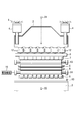
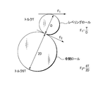
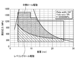
- FIG. 1 It is a side view which shows the roller leveler which concerns on one Embodiment of this invention. It is a front view which shows the roller leveler which concerns on one Embodiment of this invention. It is a figure for demonstrating the principle of this invention. Taking the sheet thickness on the horizontal axis and the yield stress on the vertical axis, the level of the leveling roll alone, and the case where only the pinch roll is pulled out, the area that can be corrected with a yield rate of 70% (0.7) FIG.
- FIG. 1 is a side view showing a roller leveler according to an embodiment of the present invention
- FIG. 2 is a front view thereof.
- the roller leveler 100 of the present embodiment corrects a cut plate-like metal plate, and supports the housing 1, the upper frame 2 provided inside the housing 1, and the housing 1 as shown in the figure. And a lower frame 3 provided in the frame.
- a hydraulic reduction cylinder (also referred to as a pressing cylinder) 4 is disposed between the housing 1 and the upper frame 2, and an upper roll frame 5 is disposed below the upper frame 2 (not shown). It is suspended by.
- a plurality of upper intermediate rolls 13 and an upper leveling roll 6 are arranged below the upper roll frame 5 so as to be supported by the upper roll frame 5.
- Each of the upper intermediate roll 13 and the upper leveling roll 6 has a long shape extending in the width direction, and the upper intermediate roll 13 is provided so as to contact the upper part of the upper leveling roll 6.
- a short upper backup roll 7 that backs up the upper intermediate roll 13 is supported by the upper roll frame 5 along the axial direction of the upper intermediate roll 13.
- the reduction cylinder 4 reduces the upper roll frame 5, the upper backup roll 7, the upper intermediate roll 13, and the upper leveling roll 6.
- the term “reducing” is intended to encompass not only the case where pressure is applied downward as shown in FIG. 1, but also the case where pressure is applied upward as described later as a modified example. To do.
- the term “pressing” can be replaced with the term “pressing”.
- a plurality of lower leveling rolls 8 are arranged on the opposite side of the upper leveling roll 6 across the pass line of the metal plate P, and a plurality of lower intermediate rolls 14 are arranged below the lower leveling roll 8. Yes.
- the lower leveling roll 8 and the lower intermediate roll 14 are supported by the lower roll frame 10 below.
- Each of the lower leveling roll 8 and the lower intermediate roll 14 has a long shape extending in the width direction, and the lower intermediate roll 14 is provided so as to contact the lower part of the lower leveling roll 8.
- a short lower backup roll 9 that backs up the lower intermediate roll 14 is supported by the lower roll frame 10 along the axial direction of the lower intermediate roll 14. Is arranged in multiple.
- the lower roll frame 10 is installed on the lower frame 3. Instead of the reduction cylinder 4 that reduces the upper leveling roll 6, a reduction cylinder that reduces the lower leveling roll 8 may be provided.
- the upper intermediate roll 13 and the lower intermediate roll 14 are configured such that their diameters are larger than the diameters of the upper leveling roll 6 and the lower leveling roll 8.
- the diameters of the upper intermediate roll 13 and the lower intermediate roll 14 are preferably 1.2 to 2.0 times, more preferably 1.4 to 2.0 times the diameters of the upper leveling roll 6 and the lower leveling roll 8.
- the pitch of the plurality of upper leveling rolls 6 and the plurality of lower leveling rolls 8 is preferably 1.2 to 2.0 times the diameter, similar to the diameter of the upper intermediate roll 13 and the lower intermediate roll 14, and is preferably 1.4 to 2 0.0 times is more preferable.
- the pitch of the conventional roller leveler is 1.02 to 1.2 times the diameter of the roller leveler, but is arranged at a pitch larger than the conventional pitch. When the pitch of the roller leveler exceeds 2.0 times the diameter, the leveling rolls enter between the opposite leveling rolls, and the yield rate cannot be increased.
- the upper intermediate roll 13 and the lower intermediate roll 14 are each provided with a driving device 15 having a rotary motor (only one is shown in FIGS. 1 and 2 for convenience), and the upper intermediate roll 13 and the lower intermediate roll 14 are , And is rotated by the driving device 15. Then, the driving force of the driving device 15 is transmitted to the upper leveling roll 6 and the lower leveling roll 8, thereby causing the metal plate P to pass between the upper leveling roll 6 and the lower leveling roll 8, and by the reduction cylinder 4. The metal plate P is pressed down through the upper leveling roll 6 to correct the metal plate P.
- a driving device 15 having a rotary motor (only one is shown in FIGS. 1 and 2 for convenience)
- the driving force of the driving device 15 is transmitted to the upper leveling roll 6 and the lower leveling roll 8, thereby causing the metal plate P to pass between the upper leveling roll 6 and the lower leveling roll 8, and by the reduction cylinder 4.
- the metal plate P is pressed down through the upper leveling roll 6 to correct the metal plate P.
- a plurality of hydraulic crowning cylinders 12 are connected between the upper frame 2 and the upper roll frame 5. As shown in FIG. 2, each crowning cylinder 12 is installed at an equal pitch so as to correspond to the leveling rolls 6 and 8 along the width direction orthogonal to the plate passing direction of the metal plate P.
- the hydraulic crowning cylinders 12 are installed in two rows as shown in FIG. In addition, although the row
- the hydraulic crowning cylinder 12 has a built-in position detection sensor (not shown). The hydraulic crowning cylinder may be provided between the lower roll frame 10 and the lower frame 3 or may be provided on both.
- a deflection detection sensor 21 for detecting the lateral deflection of the upper frame 2 is provided at the lateral center position.
- two bending detection sensors 21 are provided along the pass line of the metal plate P.
- the deflection detection sensor 21 always detects the distance to the lower end of the upper frame 2 and calculates the deflection amount of the upper frame 2 based on this distance.
- a deflection detection sensor 22 is attached to the inner space of the lower frame 3.
- Two deflection detection sensors 22 are provided along the pass line of the metal plate P at the lateral center position.
- the deflection detection sensor 22 always detects the distance to the upper end of the lower frame 3 and calculates the deflection amount of the lower frame 3 based on this distance.
- a deflection detection sensor may be provided in only one of the upper frame 2 and the lower frame 3, and the deflection amount of the other frame may be obtained by proportional calculation.
- a load cell (or hydraulic pressure converter) 23 is attached between the reduction cylinder 4 and the housing 1, so that the reduction cylinder 4, the hydraulic crowning cylinder 12, the upper roll frame 5, the upper backup roll 7, and the upper middle Compression deformation of the roll 13, the upper leveling roll 6, the lower leveling roll 8, the lower intermediate roll 14, the lower backup roll 9, and the lower roll frame 10 can be detected.
- each component is controlled by the control device 50.
- the control device 50 includes a process controller including a CPU, a user interface including a keyboard and a display, and a recipe storing a control program (software) and processing condition data. Part.
- a recipe is called from the storage unit and executed in the process controller.
- a desired process (operation sequence) described later is performed by the roller leveler 100.
- Recipes such as control programs and processing condition data are stored in computer-readable storage media such as magnetic disks (flexible disks, hard disks, etc.), optical disks (CDs, DVDs, etc.), magneto optical disks (MOs, etc.), semiconductor memories, etc. It is possible to use the one that has been made. Alternatively, the recipe can be transmitted online from another device at any time, for example, via a dedicated line.
- the control device 50 performs control of the amount of reduction (pressing amount) of the leveling roll 6 by the reduction cylinder 4 for correction (leveling) of the metal plate P, and drive control of the intermediate rolls 13 and 14 by the drive device 15. It has become. Further, the control device 50 includes the deflection information of the upper frame 2 and the lower frame 3 from the deflection detection sensors 21 and 22, or, in addition to these, the reduction cylinder 4, the hydraulic crowning cylinder 12, the upper roll frame 5, and the upper backup roll. 7. Compression deformation information of the upper intermediate roll 13, the upper leveling roll 6, the lower leveling roll 8, the lower intermediate roll 14, the lower backup roll 9, and the lower roll frame 10 is sent to the information by the calculation function of the control device 50. Based on this, the required tightening amount of each hydraulic crowning cylinder 12 is calculated, and the narrowing control of each hydraulic crowning cylinder 12 is performed based on the position information of the position detection sensor in each hydraulic crowning 12.
- an upper intermediate roll 13 and a lower intermediate roll 14 having larger diameters are provided on the upper side of the upper leveling roll 6 and the lower side of the lower leveling roll 8, respectively.
- the rolls 14 are individually rotated by the drive mechanism 15, and this rotation is transmitted to the upper leveling roll 6 and the lower leveling roll 8.
- the metal plate P is corrected by reducing the metal plate P by the reduction cylinder 4 while passing the metal plate P between the upper leveling roll 6 and the lower leveling roll 8 by the transmitted driving force.
- the plate driving force of the metal plate P is increased, and even a metal plate having a thin plate thickness and a large yield stress can be put through while providing a pressing amount necessary for correction.
- FIG. 3 is a diagram for explaining the principle of increasing the driving force by using a large-diameter intermediate roll.
- the diameters of the upper intermediate roll 13 and the lower intermediate roll 14 are preferably 1.2 to 2.0 times the diameters of the upper leveling roll 6 and the lower leveling roll 8, and 1.4 to 2 0.0 times is more preferable.
- the pitch of the plurality of upper leveling rolls 6 and the plurality of lower leveling rolls 8 is preferably 1.2 to 2.0 times the diameter, similar to the diameter of the upper intermediate roll 13 and the lower intermediate roll 14, and is preferably 1.4 to 2 0.0 times is more preferable.
- the pitch of the leveling rolls becomes wider in this way, it becomes difficult for the metal plate P to pass through when the amount of reduction of the metal plate P is increased.
- the reduction amount is reduced to allow the metal plate P to pass through, and the necessary reduction amount after the front end passes through the leveling roll arrangement region. It is preferable to correct the metal plate P.
- the metal plate P can be corrected by passing the metal plate P once through the leveling roll arrangement region, but as described above, the tip of the metal plate P has the leveling roll arrangement region.
- the metal plate P is passed through the leveling roll arrangement region one or more times. It is preferable to make it.
- the method of this embodiment is suitable for a steel plate having a thickness of 2.0 to 25.4 mm and a yield stress of 400 to 1800 MPa, which has conventionally been difficult to correct when the metal plate to be applied is a steel plate.
- FIG. 4 shows the case where the horizontal axis is the plate thickness, the vertical axis is the yield stress, the leveling roll is driven, and the case where the large diameter intermediate roll is driven and transmitted to the leveling roll according to the present embodiment.
- the correctable region is remarkably widened, and it is possible to correct even a material with a high yield stress of 1200 MPa or more in a relatively thin region with a plate thickness of 12.7 mm or less.
- the metal plate can have a high flatness.
- the relationship of FIG. 4 is performed using the leveling roll diameter whose diameter is 135 mm.
- the metal plate as the material to be corrected can be corrected with the necessary amount of reduction (pushing amount), and high flatness can be obtained.
- Components of the apparatus such as the frame 2 and the lower frame 3 may bend in the width direction. In such a case, the amount of reduction varies in the width direction of the metal plate due to the influence of the bend. Therefore, in this embodiment, when it is desired to eliminate the influence of such bending, the bending amounts of the upper frame 2 and the lower frame 3 are obtained based on the detection values of the bending detection sensors 21 and / or 22, and this bending amount is obtained.
- the necessary tightening amount of each hydraulic crowning cylinder 12 necessary to eliminate the above is calculated, and the crowning correction of the upper leveling roll 6 is performed based on the calculated amount. Thereby, the difference in the amount of reduction in the width direction of the metal plate P that is the material to be corrected can be reduced, and correction with higher flatness can be performed.
- a load cell (or a load cell) attached between the reduction cylinder 4 and the housing 1 (or Hydraulic pressure converter) 23, a reduction cylinder 4, a hydraulic crowning cylinder 12, an upper roll frame 5, an upper backup roll 7, an upper intermediate roll 13, an upper leveling roll 6, a lower leveling roll 8, a lower intermediate roll 14, and a lower backup
- the required tightening amounts of the individual hydraulic crowning cylinders 12 necessary to eliminate this compressive deformation are calculated, and the sum of both necessary tightening amounts is calculated.
- the crowning correction of the upper leveling roll 6 can be performed. That. Thereby, the difference in the amount of reduction in the width direction of the metal plate P that is the material to be corrected can be further reduced, and correction with higher flatness can be performed.
- an intermediate roll having a larger diameter than the leveling roll is brought into contact with the outside of the leveling roll, the driving force is applied to the intermediate roll, and the driving force is transmitted to the leveling roll between the leveling rolls. Since the metal plate is passed, the driving force for passing the metal plate can be increased. For this reason, even if it is a thin metal plate with a large yield stress, it can pass through, giving the amount of reduction required for correction, and the flatness of a metal plate can be made high. In addition to this, the flatness of the metal plate can be further increased by performing crowning correction in the width direction.
- the present invention is not limited to the above-described embodiment, and various modifications can be made.
- an apparatus is shown in which the upper roll of the leveling roll is pressed down (pressed downward) with respect to the lower roll.
- the lower roll may be pressed down (pressed upward) with respect to the upper roll.
Landscapes
- Engineering & Computer Science (AREA)
- Mechanical Engineering (AREA)
- Straightening Metal Sheet-Like Bodies (AREA)
- Casting Or Compression Moulding Of Plastics Or The Like (AREA)
Abstract
Priority Applications (2)
| Application Number | Priority Date | Filing Date | Title |
|---|---|---|---|
| KR1020137023456A KR20130118986A (ko) | 2011-02-24 | 2012-02-03 | 롤러 레벨러 및 금속판의 교정 방법 |
| US14/001,265 US20130327111A1 (en) | 2011-02-24 | 2012-02-03 | Roller leveler and metal sheet flattening method |
Applications Claiming Priority (2)
| Application Number | Priority Date | Filing Date | Title |
|---|---|---|---|
| JP2011-038046 | 2011-02-24 | ||
| JP2011038046A JP2012171004A (ja) | 2011-02-24 | 2011-02-24 | ローラレベラおよび金属板の矯正方法 |
Publications (1)
| Publication Number | Publication Date |
|---|---|
| WO2012114852A1 true WO2012114852A1 (fr) | 2012-08-30 |
Family
ID=46691349
Family Applications (1)
| Application Number | Title | Priority Date | Filing Date |
|---|---|---|---|
| PCT/JP2012/052532 Ceased WO2012114852A1 (fr) | 2011-02-24 | 2012-02-03 | Niveleuse à cylindres et procédé de nivellement à plaque métallique |
Country Status (5)
| Country | Link |
|---|---|
| US (1) | US20130327111A1 (fr) |
| JP (1) | JP2012171004A (fr) |
| KR (1) | KR20130118986A (fr) |
| CN (2) | CN202921694U (fr) |
| WO (1) | WO2012114852A1 (fr) |
Cited By (2)
| Publication number | Priority date | Publication date | Assignee | Title |
|---|---|---|---|---|
| ITGE20130070A1 (it) * | 2013-07-24 | 2015-01-25 | Sandro Brizielli | Linea multiuso per la produzione di lamiere |
| CN115955780A (zh) * | 2023-03-13 | 2023-04-11 | 四川英创力电子科技股份有限公司 | 一种大尺寸印制板的高效校平装置及方法 |
Families Citing this family (9)
| Publication number | Priority date | Publication date | Assignee | Title |
|---|---|---|---|---|
| JP2012171004A (ja) * | 2011-02-24 | 2012-09-10 | Jp Steel Plantech Co | ローラレベラおよび金属板の矯正方法 |
| CN105195559B (zh) * | 2014-06-25 | 2017-02-22 | 宝山钢铁股份有限公司 | 厚板横向板形冷矫直方法 |
| CN105947749A (zh) * | 2016-06-23 | 2016-09-21 | 湖南众满轮胎科技有限公司 | 防扎穿安全轮胎的环形链板带链块冲压的薄钢带输送机 |
| US10010918B2 (en) | 2016-10-05 | 2018-07-03 | Allor Manufacturing Inc. | Device and method for leveling a metal plate |
| CN111069344A (zh) * | 2019-12-30 | 2020-04-28 | 昆山全亚冠环保科技有限公司 | 一种用于靶材背板的精密矫直工艺 |
| CN115519004B (zh) * | 2022-10-21 | 2025-12-30 | 宁波江丰电子材料股份有限公司 | 一种脆性金属靶材的去应力整形方法 |
| KR102885088B1 (ko) | 2023-06-21 | 2025-11-12 | 최무건 | 절곡된 금속판을 연속 가압하여 교정하는 금속판용 교정 장치 |
| CN116944279B (zh) * | 2023-07-25 | 2026-01-06 | 中冶京诚工程技术有限公司 | 全液压恒辊缝矫直机 |
| CN116921497A (zh) * | 2023-07-25 | 2023-10-24 | 中冶京诚工程技术有限公司 | 多点弯辊补偿装置及矫直机 |
Citations (5)
| Publication number | Priority date | Publication date | Assignee | Title |
|---|---|---|---|---|
| JPS60145219A (ja) * | 1983-12-29 | 1985-07-31 | Ishikawajima Harima Heavy Ind Co Ltd | ロ−ラ−レベラ−及び該ロ−ラ−レベラ−の使用方法 |
| JPH11300420A (ja) * | 1998-04-20 | 1999-11-02 | Sumitomo Heavy Ind Ltd | ローラレベラ |
| JP3443036B2 (ja) * | 1999-05-20 | 2003-09-02 | 住友重機械工業株式会社 | ローラレベラーのクラウニング補正方法およびクラウニング装置 |
| JP2005152964A (ja) * | 2003-11-27 | 2005-06-16 | Nippon Steel Corp | ローラ矯正方法 |
| JP2009516592A (ja) * | 2005-11-22 | 2009-04-23 | シーメンス ヴェ メタルス テクノロジーズ エスアーエス | 噛合したロールを備えたレベリング機内でストリップ状またはシート状の平坦な物体をレベリングする方法およびそのレベリング装置 |
Family Cites Families (6)
| Publication number | Priority date | Publication date | Assignee | Title |
|---|---|---|---|---|
| JP2524022B2 (ja) * | 1991-08-28 | 1996-08-14 | 新日本製鐵株式会社 | ロ―ルピッチ可変ロ―ラレベラ |
| DE4415048A1 (de) * | 1994-04-29 | 1995-11-02 | Schloemann Siemag Ag | Richtmaschine zum Richten von Blechen und Bändern |
| CN1693000A (zh) * | 2005-02-18 | 2005-11-09 | 中冶连铸技术工程股份有限公司 | 带钢弯曲矫直机辊组及其矫直机 |
| JP2008100260A (ja) * | 2006-10-19 | 2008-05-01 | Jfe Steel Kk | 鋼板の連続矯正方法 |
| US8893537B2 (en) * | 2007-11-07 | 2014-11-25 | The Bradbury Company, Inc. | Methods and apparatus to drive material conditioning machines |
| JP2012171004A (ja) * | 2011-02-24 | 2012-09-10 | Jp Steel Plantech Co | ローラレベラおよび金属板の矯正方法 |
-
2011
- 2011-02-24 JP JP2011038046A patent/JP2012171004A/ja active Pending
-
2012
- 2012-02-03 US US14/001,265 patent/US20130327111A1/en not_active Abandoned
- 2012-02-03 KR KR1020137023456A patent/KR20130118986A/ko not_active Ceased
- 2012-02-03 WO PCT/JP2012/052532 patent/WO2012114852A1/fr not_active Ceased
- 2012-02-23 CN CN2012200630036U patent/CN202921694U/zh not_active Expired - Fee Related
- 2012-02-23 CN CN2012100438356A patent/CN102649132A/zh active Pending
Patent Citations (5)
| Publication number | Priority date | Publication date | Assignee | Title |
|---|---|---|---|---|
| JPS60145219A (ja) * | 1983-12-29 | 1985-07-31 | Ishikawajima Harima Heavy Ind Co Ltd | ロ−ラ−レベラ−及び該ロ−ラ−レベラ−の使用方法 |
| JPH11300420A (ja) * | 1998-04-20 | 1999-11-02 | Sumitomo Heavy Ind Ltd | ローラレベラ |
| JP3443036B2 (ja) * | 1999-05-20 | 2003-09-02 | 住友重機械工業株式会社 | ローラレベラーのクラウニング補正方法およびクラウニング装置 |
| JP2005152964A (ja) * | 2003-11-27 | 2005-06-16 | Nippon Steel Corp | ローラ矯正方法 |
| JP2009516592A (ja) * | 2005-11-22 | 2009-04-23 | シーメンス ヴェ メタルス テクノロジーズ エスアーエス | 噛合したロールを備えたレベリング機内でストリップ状またはシート状の平坦な物体をレベリングする方法およびそのレベリング装置 |
Cited By (3)
| Publication number | Priority date | Publication date | Assignee | Title |
|---|---|---|---|---|
| ITGE20130070A1 (it) * | 2013-07-24 | 2015-01-25 | Sandro Brizielli | Linea multiuso per la produzione di lamiere |
| CN115955780A (zh) * | 2023-03-13 | 2023-04-11 | 四川英创力电子科技股份有限公司 | 一种大尺寸印制板的高效校平装置及方法 |
| CN115955780B (zh) * | 2023-03-13 | 2023-05-09 | 四川英创力电子科技股份有限公司 | 一种大尺寸印制板的高效校平装置及方法 |
Also Published As
| Publication number | Publication date |
|---|---|
| KR20130118986A (ko) | 2013-10-30 |
| CN102649132A (zh) | 2012-08-29 |
| JP2012171004A (ja) | 2012-09-10 |
| CN202921694U (zh) | 2013-05-08 |
| US20130327111A1 (en) | 2013-12-12 |
Similar Documents
| Publication | Publication Date | Title |
|---|---|---|
| WO2012114852A1 (fr) | Niveleuse à cylindres et procédé de nivellement à plaque métallique | |
| WO2012114853A1 (fr) | Niveleuse à cylindres et procédé de nivellement de plaque métallique | |
| KR101559159B1 (ko) | 롤러 레벨러 및 판재의 교정 방법 | |
| JP5883455B2 (ja) | ローラレベラおよびそれを用いた板材の矯正方法 | |
| CN102548681B (zh) | 用于连续拉伸-弯曲-校平金属带的方法和装置 | |
| JP5856535B2 (ja) | ローラレベラおよびそれを用いた板材の矯正方法 | |
| JP4214150B2 (ja) | 金属板材の圧延方法および圧延装置 | |
| JP2012171004A5 (fr) | ||
| JP5797011B2 (ja) | ローラレベラを用いた金属板の処理設備および処理方法 | |
| JP5742703B2 (ja) | 金属板材の圧延機および圧延方法 | |
| WO2013035449A1 (fr) | Machine à planer et procédé de planage de plaque métallique utilisant ce niveleur | |
| JP2009255148A (ja) | ローラレベラ | |
| JP4894188B2 (ja) | U型鋼矢板のローラー矯正方法および装置 | |
| JP5041006B2 (ja) | ゼンジミアミルのロールポジション設定方法 | |
| TWI505879B (zh) | Roller straightening machine and plate correction method | |
| JP2017006941A (ja) | ローラーレベラの零点調整方法 | |
| JP5396827B2 (ja) | 板圧延方法 | |
| CN221246546U (zh) | 一种条形铝材辊压结构 | |
| KR20120073450A (ko) | 판재의 인장 교정 장치 및 방법 | |
| JP4533263B2 (ja) | 厚鋼板の矯正方法および矯正装置 | |
| JP2003039113A (ja) | ローラレベラ | |
| JP2003136138A (ja) | 全長における断面寸法形状および真直性に優れた形鋼の矯正方法 | |
| JP2005000958A (ja) | 金属板の製造方法とそれに用いる矯正装置 |
Legal Events
| Date | Code | Title | Description |
|---|---|---|---|
| 121 | Ep: the epo has been informed by wipo that ep was designated in this application |
Ref document number: 12749833 Country of ref document: EP Kind code of ref document: A1 |
|
| WWE | Wipo information: entry into national phase |
Ref document number: 14001265 Country of ref document: US |
|
| NENP | Non-entry into the national phase |
Ref country code: DE |
|
| ENP | Entry into the national phase |
Ref document number: 20137023456 Country of ref document: KR Kind code of ref document: A |
|
| 122 | Ep: pct application non-entry in european phase |
Ref document number: 12749833 Country of ref document: EP Kind code of ref document: A1 |