WO2012114853A1 - Niveleuse à cylindres et procédé de nivellement de plaque métallique - Google Patents
Niveleuse à cylindres et procédé de nivellement de plaque métallique Download PDFInfo
- Publication number
- WO2012114853A1 WO2012114853A1 PCT/JP2012/052533 JP2012052533W WO2012114853A1 WO 2012114853 A1 WO2012114853 A1 WO 2012114853A1 JP 2012052533 W JP2012052533 W JP 2012052533W WO 2012114853 A1 WO2012114853 A1 WO 2012114853A1
- Authority
- WO
- WIPO (PCT)
- Prior art keywords
- metal plate
- leveling
- roll
- unit
- pressing
- Prior art date
- Legal status (The legal status is an assumption and is not a legal conclusion. Google has not performed a legal analysis and makes no representation as to the accuracy of the status listed.)
- Ceased
Links
Images





Classifications
-
- B—PERFORMING OPERATIONS; TRANSPORTING
- B21—MECHANICAL METAL-WORKING WITHOUT ESSENTIALLY REMOVING MATERIAL; PUNCHING METAL
- B21D—WORKING OR PROCESSING OF SHEET METAL OR METAL TUBES, RODS OR PROFILES WITHOUT ESSENTIALLY REMOVING MATERIAL; PUNCHING METAL
- B21D1/00—Straightening, restoring form or removing local distortions of sheet metal or specific articles made therefrom; Stretching sheet metal combined with rolling
- B21D1/05—Stretching combined with rolling
-
- B—PERFORMING OPERATIONS; TRANSPORTING
- B21—MECHANICAL METAL-WORKING WITHOUT ESSENTIALLY REMOVING MATERIAL; PUNCHING METAL
- B21B—ROLLING OF METAL
- B21B1/00—Metal-rolling methods or mills for making semi-finished products of solid or profiled cross-section; Sequence of operations in milling trains; Layout of rolling-mill plant, e.g. grouping of stands; Succession of passes or of sectional pass alternations
- B21B1/22—Metal-rolling methods or mills for making semi-finished products of solid or profiled cross-section; Sequence of operations in milling trains; Layout of rolling-mill plant, e.g. grouping of stands; Succession of passes or of sectional pass alternations for rolling plates, strips, bands or sheets of indefinite length
- B21B1/30—Metal-rolling methods or mills for making semi-finished products of solid or profiled cross-section; Sequence of operations in milling trains; Layout of rolling-mill plant, e.g. grouping of stands; Succession of passes or of sectional pass alternations for rolling plates, strips, bands or sheets of indefinite length in a non-continuous process
-
- B—PERFORMING OPERATIONS; TRANSPORTING
- B21—MECHANICAL METAL-WORKING WITHOUT ESSENTIALLY REMOVING MATERIAL; PUNCHING METAL
- B21B—ROLLING OF METAL
- B21B31/00—Rolling stand structures; Mounting, adjusting, or interchanging rolls, roll mountings, or stand frames
- B21B31/16—Adjusting or positioning rolls
- B21B31/20—Adjusting or positioning rolls by moving rolls perpendicularly to roll axis
-
- B—PERFORMING OPERATIONS; TRANSPORTING
- B21—MECHANICAL METAL-WORKING WITHOUT ESSENTIALLY REMOVING MATERIAL; PUNCHING METAL
- B21B—ROLLING OF METAL
- B21B37/00—Control devices or methods specially adapted for metal-rolling mills or the work produced thereby
- B21B37/28—Control of flatness or profile during rolling of strip, sheets or plates
- B21B37/38—Control of flatness or profile during rolling of strip, sheets or plates using roll bending
-
- B—PERFORMING OPERATIONS; TRANSPORTING
- B21—MECHANICAL METAL-WORKING WITHOUT ESSENTIALLY REMOVING MATERIAL; PUNCHING METAL
- B21D—WORKING OR PROCESSING OF SHEET METAL OR METAL TUBES, RODS OR PROFILES WITHOUT ESSENTIALLY REMOVING MATERIAL; PUNCHING METAL
- B21D1/00—Straightening, restoring form or removing local distortions of sheet metal or specific articles made therefrom; Stretching sheet metal combined with rolling
- B21D1/02—Straightening, restoring form or removing local distortions of sheet metal or specific articles made therefrom; Stretching sheet metal combined with rolling by rollers
-
- B—PERFORMING OPERATIONS; TRANSPORTING
- B21—MECHANICAL METAL-WORKING WITHOUT ESSENTIALLY REMOVING MATERIAL; PUNCHING METAL
- B21B—ROLLING OF METAL
- B21B13/00—Metal-rolling stands, i.e. an assembly composed of a stand frame, rolls, and accessories
- B21B13/14—Metal-rolling stands, i.e. an assembly composed of a stand frame, rolls, and accessories having counter-pressure devices acting on rolls to inhibit deflection of same under load; Back-up rolls
-
- B—PERFORMING OPERATIONS; TRANSPORTING
- B21—MECHANICAL METAL-WORKING WITHOUT ESSENTIALLY REMOVING MATERIAL; PUNCHING METAL
- B21B—ROLLING OF METAL
- B21B15/00—Arrangements for performing additional metal-working operations specially combined with or arranged in, or specially adapted for use in connection with, metal-rolling mills
- B21B2015/0071—Levelling the rolled product
-
- B—PERFORMING OPERATIONS; TRANSPORTING
- B21—MECHANICAL METAL-WORKING WITHOUT ESSENTIALLY REMOVING MATERIAL; PUNCHING METAL
- B21B—ROLLING OF METAL
- B21B2273/00—Path parameters
- B21B2273/06—Threading
-
- B—PERFORMING OPERATIONS; TRANSPORTING
- B21—MECHANICAL METAL-WORKING WITHOUT ESSENTIALLY REMOVING MATERIAL; PUNCHING METAL
- B21B—ROLLING OF METAL
- B21B41/00—Guiding, conveying, or accumulating easily-flexible work, e.g. wire, sheet metal bands, in loops or curves; Loop lifters
- B21B41/02—Returning work to repeat the pass or passes within the same stand
-
- B—PERFORMING OPERATIONS; TRANSPORTING
- B21—MECHANICAL METAL-WORKING WITHOUT ESSENTIALLY REMOVING MATERIAL; PUNCHING METAL
- B21B—ROLLING OF METAL
- B21B41/00—Guiding, conveying, or accumulating easily-flexible work, e.g. wire, sheet metal bands, in loops or curves; Loop lifters
- B21B41/06—Guiding, conveying, or accumulating easily-flexible work, e.g. wire, sheet metal bands, in loops or curves; Loop lifters in which the direction of movement of the work is turned through approximately 180 degrees, e.g. repeaters, i.e. from one stand to another
Definitions
- the present invention relates to a roller leveler for correcting a cut-plate-like metal plate and a method for correcting the metal plate.
- a roller leveler in which a plurality of leveling rolls are arranged in a zigzag manner in the vertical direction is used for the purpose of correcting such warpage and wave shape deformation to flatten the metal plate (for example, Patent Document 1).
- the roller leveler is a state in which the upper roll is pushed into the lower roll or the lower roll is pushed into the upper roll. Flatten warpage and wave shape. At this time, the pressing amount of each roll of the roller leveler is appropriately set so that the metal plate is preferably bent at a yield rate of 0.7 or more.
- the driving force when passing the metal plate depends on the torque of the leveling roll, but corrects a thin metal plate with a large yield stress. At that time, it is necessary to reduce the roll diameter, and if it is attempted to secure the pushing amount necessary for correction, a situation occurs where the work roll torque is insufficient and the sheet cannot be passed.
- the present invention has been made in view of such a situation, and it is an object of the present invention to provide a roller leveler and a metal plate correction method that can sufficiently correct even a thin metal plate having a large yield stress. To do.
- a roller leveler for correcting a cut plate-like metal plate, which is arranged in a zigzag manner above and below a plate passing line of the metal plate to be corrected.
- a plurality of leveling rolls that rotate so as to pass the metal plate while correcting the metal plate, a hydraulic pressure cylinder that presses the metal plate through the leveling roll, and a metal plate that rotates the leveling roll
- the drive device is pressed while pressing the metal plate through the leveling roll with a pressing amount necessary for correcting the metal plate by the pressing cylinder.
- a roller leveler for correcting a cut plate-like metal plate is disposed in a zigzag pattern above and below the plate passing line of the metal plate to be corrected, and the metal is corrected while sandwiching the metal plate.
- Leveling roll having a plurality of leveling rolls rotating so as to pass the plate, a hydraulic pressing cylinder pressing the metal plate via the leveling roll, and a driving device for rotating the leveling roll to pass the metal plate
- a first pinch having a unit and a pair of pinch rolls provided on both outer portions of the leveling roll arrangement area where the leveling roll is arranged in the pass line of the metal plate, both of which provide a pulling force across the metal plate
- a roll unit and a second pinch roll unit and a control device for controlling the correction of the metal plate.
- a metal plate is passed through the driving device by the pressing cylinder or in a state where the metal plate is not pressed along the first direction from the first pinch roll unit side to the second pinch roll unit side in the leveling roll arrangement region.
- the plate is passed in a state where the plate can be pressed with a pressing amount as much as possible, and when the tip of the metal plate reaches the second pinch roll unit, the pressing amount by the pressing cylinder is necessary for correcting the metal plate.
- the second pinch roll unit applies a pulling force in the first direction to the metal plate so that the rear plate passes through the leveling roll arrangement region.
- the feeding direction of the metal plate is changed to the second direction opposite to the first direction, and the metal plate is pressed against the leveling roll arrangement region.
- the first pinch roll is used to control the metal plate to pass through the drawing force in the second direction.
- a roller leveler is provided.
- a roller leveler for correcting a cut-plate-shaped metal plate, which is arranged in a zigzag pattern above and below the plate passing line of the metal plate to be corrected, and is corrected while sandwiching the metal plate.
- Leveling roll having a plurality of leveling rolls rotating so as to pass the plate, a hydraulic pressing cylinder pressing the metal plate via the leveling roll, and a driving device for rotating the leveling roll to pass the metal plate
- a pinch roll unit including a unit and a pair of pinch rolls provided on one outer portion of a leveling roll arrangement region in which the leveling rolls are arranged on a metal plate pass line, and applying a pulling force across the metal plate;
- a metal plate reversing mechanism that is provided on the other outer portion of the leveling roll arrangement region and reverses the front and rear ends of the metal plate;
- a control device for controlling the correction of the metal plate, wherein the control device is not pressed from the metal plate reversing mechanism side of the leveling unit to the leveling roll arrangement region or by the pressing cylinder.
- the plate is passed in a state of being pressed with a pressing amount capable of passing by the driving device, and when the tip of the metal plate reaches the pinch roll unit, the pressing amount by the pressing cylinder is corrected.
- the metal plate is removed from the metal plate by the pulling force applied to the metal plate by the pinch roll unit.
- the leveling roll is fed from the metal plate reversing mechanism side by feeding the plate reversing mechanism to reverse the front and rear ends of the metal plate and reversing the metal plate.
- roller leveler characterized in that the pressing amount by the pressing cylinder is increased to an amount necessary for correcting the metal plate, and the pinch roll unit applies a pulling force to the metal plate to pass it.
- roller levelers for correcting a cut plate-like metal plate, which are respectively arranged in a zigzag pattern above and below the sheet plate line of the metal plate to be corrected, and are corrected with the metal plate interposed therebetween.
- a plurality of leveling rolls rotating to allow the metal plate to pass through, a hydraulic pressing cylinder for pressing the metal plate via the leveling roll, and a drive device for rotating the leveling roll to pass the metal plate A first leveling unit and a second leveling unit that are arranged along the plate passing direction of the metal plate, and are provided between the first leveling unit and the second leveling unit, and are drawn with the metal plate interposed therebetween.
- the leveling of the first leveling unit is performed by setting the knit to a state where the metal plate is not pressed or a state where the metal plate is pressed by the pressing cylinder with a pressing amount that can be passed by the driving device.
- the first leveling roll arrangement area where the roll is arranged is passed toward the second leveling unit in a state where it is not pressed or is pressed by the pressing cylinder with a pressing amount that can be passed by the driving device.
- the amount of pressing by the pressing cylinder of the first leveling unit is increased to an amount necessary for correcting the metal plate, and the pinch roll
- the unit applies a pulling force to the metal plate to let the metal plate pass, and the rear end of the metal plate is the pinch.
- the first leveling unit is brought into a state where the metal plate is not pressed or a state where the metal plate is pressed by the pressing cylinder with a pressing amount that can be passed by the driving device,
- the pressing amount of the second leveling unit by the pressing cylinder is increased to an amount necessary for the correction of the metal plate, and a pulling force is applied to the metal plate by the pinch roll unit to move the metal plate to the first leveling unit.
- a roller leveler characterized in that it passes through the plate.
- a plurality of leveling rolls arranged in a zigzag pattern above and below the plate passing line of the metal plate to be corrected, and rotated so as to pass the metal plate while correcting with the metal plate interposed therebetween,
- a plurality of backup rolls that back up the plurality of leveling rolls; a pair of roll frames that support the leveling roll and the backup roll above and below; and a pair of frames that support the pair of roll frames up and down.
- a hydraulic pressing cylinder that presses one of the pair of frames and presses one of the roll frames and the metal plate via the leveling roll, a drive device that rotates the leveling roll, and the pressing cylinder The metal plate passes between the frame pressed by the roller and the corresponding roll frame.
- a plurality of hydraulic crowning cylinders mounted along the width direction orthogonal to the direction and the leveling roll arrangement area where the leveling roll is arranged in the pass line of the metal plate, and pulling force across the metal plate
- a pinch roll unit having a pair of pinch rolls and a control device for controlling the correction of the metal plate, wherein the control device uses the pressing cylinder to press the leveling roll with a pressing amount necessary for the correction of the metal plate.
- the metal plate is controlled to pass between the leveling rolls by the driving force by the driving device and the pulling force by the pinch roll while pressing the metal plate through, and the control device is
- the individual hydraulic crowning required to determine the amount of lateral deflection of the pair of frames and eliminate the amount of deflection. Calculates the necessary tightening of Linda, it provides a roller leveler and controls tighten the individual hydraulic crowning cylinders based on the necessary tightening amount.
- the control device is necessary to eliminate the compression deformation based on the compression deformation information of the pressing cylinder, the hydraulic crowning cylinder, the pair of roll frames, the backup roll, and the leveling roll.
- the required tightening amount of each individual hydraulic crowning cylinder is calculated, and the individual hydraulic crowning is calculated based on the total amount of the necessary tightening amount and the necessary tightening amount to eliminate the deflection amount of the pair of frames. It is preferable to perform tightening control of the cylinder.
- a plurality of leveling rolls arranged in a zigzag pattern above and below the plate passing line of the metal plate to be corrected, and rotated so as to pass the metal plate while correcting with the metal plate interposed therebetween, ,
- a hydraulic pressure cylinder that presses the metal plate through the leveling roll, a driving device that rotates the leveling roll to pass the metal plate, and a leveling in which the leveling roll is disposed in a pass line of the metal plate
- the drive is performed while pressing the metal plate through the leveling roll with a pressing amount necessary for correcting the metal plate by the pressing cylinder. It provides a method of correcting a metal sheet, characterized in that to Tsuban the metal plate by pulling force by the driving force and the pinch rolls due to location between the leveling rolls.
- a plurality of leveling rolls that are arranged in a zigzag pattern above and below the plate passing line of the metal plate to be corrected and rotate so as to pass the metal plate while correcting the metal plate in between,
- a hydraulic pressure cylinder that presses the metal plate through the leveling roll, a leveling unit having a driving device that rotates the leveling roll to pass the metal plate, and the leveling roll in the metal plate pass line are disposed.
- a first pinch roll unit and a second pinch roll unit each having a pair of pinch rolls which are provided on both outer portions of the leveling roll arrangement region and which provide a pulling force across the metal plate.
- a metal plate correction method for correcting a cut plate-like metal plate using a roller leveler wherein the metal plate is a first pin. Pressing the leveling roll placement area along the first direction from the chill roll unit side toward the second pinch roll unit side in a state where the leveling roll is not pressed or with a pressing amount capable of passing by the driving device by the pressing cylinder And when the tip of the metal plate reaches the second pinch roll unit, the pressing amount by the pressing cylinder is increased to an amount necessary for correcting the metal plate, and the first When the rear end of the metal plate passes through the leveling roll arrangement area, the metal plate is fed in the feeding direction by applying a pulling force in the first direction to the metal plate by the two pinch roll units.
- the metal plate is not pressed against the leveling roll arrangement region or the pressing cylinder.
- the pressing amount by the pressing cylinder Is increased to an amount necessary for the correction of the metal plate, and the metal plate is passed through the first pinch roll by applying a pulling force in the second direction to the metal plate.
- a plurality of leveling rolls that are arranged in a zigzag pattern above and below the plate passing line of the metal plate to be corrected, and rotate so as to pass the metal plate while correcting the metal plate therebetween,
- a hydraulic pressure cylinder that presses the metal plate through the leveling roll
- a leveling unit having a driving device that rotates the leveling roll to pass the metal plate
- the leveling roll in the metal plate pass line are disposed.
- a pinch roll unit having a pair of pinch rolls that are provided at one outer portion of the leveling roll arrangement region and that provides a pulling force across the metal plate, and is provided at the other outer portion of the leveling roll arrangement region.
- a metal plate reversing mechanism for reversing the front and rear ends of the plate, and a cut-plate-shaped metal plate using a roller leveler A method for correcting a metal plate to be corrected, wherein the metal plate is not pressed from the metal plate reversing mechanism side of the leveling unit to the leveling roll arrangement region or is capable of being passed by the driving device with the pressing cylinder. And when the tip of the metal plate reaches the pinch roll unit, the pressing amount by the pressing cylinder is increased to an amount necessary for the correction of the metal plate.
- the pinch roll unit applies a pulling force to the metal plate to pass the metal plate, and when the rear end of the metal plate passes through the leveling roll arrangement region, the metal plate is fed to the metal plate reversing mechanism to form a metal.
- the front end and the rear end of the plate are reversed, and the reversed metal plate is not pressed from the metal plate reversing mechanism side to the leveling roll arrangement region or the front
- the pressing amount by the pressing cylinder is reduced to the metal.
- a method for correcting a metal plate characterized in that it increases to an amount necessary for correcting the plate, and passes through the metal plate by applying a pulling force to the metal plate by the pinch roll unit.
- a plurality of levelings that are arranged in a zigzag pattern above and below the plate passing line of the metal plate to be corrected and rotate so as to pass the metal plate while correcting with the metal plate interposed therebetween.
- a metal plate correction method for correcting a cut plate-like metal plate using a roller leveler comprising: a metal plate pressed against the second leveling unit. As a state where there is no metal plate or a state where the metal plate is pressed by the driving device with a pressing amount capable of passing through the driving device, the metal plate is used as the first leveling roll of the first leveling unit.
- the pressing amount by the pressing cylinder of the first leveling unit is increased to an amount necessary for correcting the metal plate, and the pulling force is applied to the metal plate by the pinch roll unit.
- the first leveling unit is in a state in which the metal plate is not pressed or in a state in which the metal plate is pressed with a pressing amount that can be passed by the driving device by the pressing cylinder, by the pressing cylinder of the second leveling unit.
- the pressing amount is increased to an amount necessary for the correction of the metal plate, and a pulling force is applied to the metal plate by the pinch roll unit to pass the metal plate toward the first leveling unit.
- a method for correcting a metal plate is provided.
- a plurality of leveling rolls arranged in a zigzag pattern above and below the plate passing line of the metal plate to be corrected, and rotated so as to pass the metal plate while correcting with the metal plate interposed therebetween.
- a plurality of backup rolls that back up the plurality of leveling rolls; a pair of roll frames that support the leveling roll and the backup roll above and below; and a pair of frames that support the pair of roll frames up and down.
- a hydraulic pressing cylinder that presses one of the pair of frames and presses one of the roll frames and the metal plate via the leveling roll, a drive device that rotates the leveling roll, and the pressing cylinder Between the metal frame pressed between the frame and the corresponding roll frame.
- a plurality of hydraulic crowning cylinders mounted along the width direction perpendicular to the plate direction and the leveling roll arrangement area where the leveling roll is arranged in the metal plate pass line are pulled out across the metal plate.
- a pinch roll unit having a pair of pinch rolls for applying a force, and a metal plate correction method for correcting a cut plate-like metal plate using a roller leveler, which is necessary for correcting the metal plate by the pressing cylinder While pressing the metal plate through the leveling roll with a pressing amount, the metal plate is passed between the leveling rolls by the driving force by the driving device and the pulling force by the pinch roll, and the pair of frames
- the lateral deflection amount of the individual hydraulic crowning cylinder necessary for eliminating this deflection amount is calculated. Calculating a main fastening amount, provides a method of correcting metal plate and controlling tighten the individual hydraulic crowning cylinders based on the necessary tightening amount.
- the individual hydraulic pressures necessary to eliminate the compression deformation Calculate the required tightening amount of the type crowning cylinder, and tighten the individual hydraulic crowning cylinders based on the total value of the necessary tightening amount and the necessary tightening amount to eliminate the bending amount of the pair of frames. It is preferable to control.
- the metal plate to be corrected in the present invention is preferably a steel plate having a thickness of 2.0 to 25.4 mm and a yield stress of 400 to 1800 MPa.
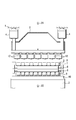
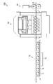
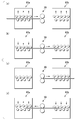
- FIG. 1 It is a side view which shows the roller leveler which concerns on one Embodiment of this invention. It is a front view which shows the roller leveler which concerns on one Embodiment of this invention. It is a figure for demonstrating the correction operation
- FIG. 1 is a side view showing a roller leveler according to an embodiment of the present invention
- FIG. 2 is a front view thereof.
- the roller leveler 100 of the present embodiment corrects a cut plate-like metal plate, and has a leveling unit 60 as shown in the figure.
- the leveling unit includes a housing 1, an upper frame 2 provided inside the housing 1, and a lower frame 3 provided so as to support the housing 1.
- a hydraulic reduction cylinder (also referred to as a pressing cylinder) 4 is disposed between the housing 1 and the upper frame 2, and an upper roll frame 5 is disposed below the upper frame 2 (not shown). It is suspended by.
- the reduction cylinder 4 reduces the upper roll frame 5, the upper backup roll 7, and the upper leveling roll 6.
- the term “reducing” is intended to encompass not only the case where pressure is applied downward as shown in FIG. 1, but also the case where pressure is applied upward as described later as a modified example. To do. In other words, in this specification, the term “pressing” can be replaced with the term “pressing”.
- a plurality of lower leveling rolls 8 are arranged on the opposite side of the upper leveling roll 6 across the pass line of the metal plate P, and the lower leveling roll 8 is supported by the lower roll frame 10 below the lower leveling roll 8. . Between each leveling roll 8 and the lower roll frame 10, a short lower backup roll 9 that backs up the lower leveling roll 8 is supported by the lower roll frame 10 along the axial direction of the lower leveling roll 8. Several are arranged.
- the lower roll frame 10 is installed on the lower frame 3. Instead of the reduction cylinder 4 that reduces the upper leveling roll 6, a reduction cylinder that reduces the lower leveling roll 8 may be provided.
- the upper leveling roll 6 and the lower leveling roll 8 are each provided with a driving device 15 having a rotary motor (only one is shown in FIG. 1 for convenience).
- the upper leveling roll 6 and the lower leveling roll 8 are driven. It is rotated by the device 15. Then, while the metal plate P is passed between the upper leveling roll 6 and the lower leveling roll 8 by the driving device 15, the metal plate P is reduced by the reduction cylinder 4 via the upper leveling roll 6. It comes to correct.
- each crowning cylinder 12 is installed at an equal pitch so as to correspond to the leveling rolls 6 and 8 along the width direction orthogonal to the plate passing direction of the metal plate P.
- the hydraulic crowning cylinders 12 are installed in two rows as shown in FIG.
- column of a crowning cylinder may be 1 row
- the hydraulic crowning cylinder 12 has a built-in position detection sensor (not shown).
- a deflection detection sensor 21 for detecting the lateral deflection of the upper frame 2 is provided at the lateral center position.
- two bending detection sensors 21 are provided along the pass line of the metal plate P.
- the deflection detection sensor 21 always detects the distance to the lower end of the upper frame 2 and calculates the deflection amount of the upper frame 2 based on this distance.
- a deflection detection sensor 22 is attached to the inner space of the lower frame 3.
- Two deflection detection sensors 22 are provided along the pass line of the metal plate P at the lateral center position.
- the deflection detection sensor 22 always detects the distance to the upper end of the lower frame 3 and calculates the deflection amount of the lower frame 3 based on this distance.
- a deflection detection sensor may be provided in only one of the upper frame 2 and the lower frame 3, and the deflection amount of the other frame may be obtained by proportional calculation.
- a load cell (or a hydraulic pressure converter) 23 is attached between the reduction cylinder 4 and the housing 1, and thereby, the reduction cylinder 4, the hydraulic crowning cylinder 12, the upper roll frame 5, the upper backup roll 7, and the upper leveling. Compression deformation of the roll 6, the lower leveling roll 8, the lower backup roll 9, and the lower roll frame 10 can be detected.
- a first pinch roll unit 30a having a pair of pinch rolls 31a for sandwiching and pulling out the metal plate P and a pair of pinch rolls 31b are provided on both outer portions of the leveling roll arrangement region in the pass line of the metal plate P, respectively.
- a second pinch roll unit 30b is provided. The distance between the pair of pinch rolls 31a is adjusted by the pinch roll cylinder 32a, and the distance between the pair of pinch rolls 31b is adjusted by the pinch roll cylinder 32b. Further, the pinch roll 31a and the pinch roll 31b are rotated by driving devices 33a and 33b each having a rotation motor, thereby giving a pulling force for pulling out the metal plate P as the material to be corrected. Note that guide rolls 34a and 34b are provided between the pair of pinch rolls 31a and the leveling roll arrangement area and between the pair of pinch rolls 31b and the leveling roll arrangement area, respectively.
- a plurality of optical sensors 41 are provided between the pinch rolls 31a and 31b as a position detection mechanism for detecting the position of the tip of the metal plate P along the pass line. After the tip is detected by the optical sensor 41, the tip of the metal plate P is tracked using a pulse generator (not shown).
- each component is controlled by the control device 50.
- the control device 50 includes a process controller including a CPU, a user interface including a keyboard and a display, and a recipe storing a control program (software) and processing condition data. Part.
- a recipe is called from the storage unit and executed in the process controller.
- a desired process (operation sequence) described later is performed by the roller leveler 100.
- Recipes such as control programs and processing condition data are stored in computer-readable storage media such as magnetic disks (flexible disks, hard disks, etc.), optical disks (CDs, DVDs, etc.), magneto optical disks (MOs, etc.), semiconductor memories, etc. It is possible to use the one that has been made. Alternatively, the recipe can be transmitted online from another device at any time, for example, via a dedicated line.
- the control device 50 controls the reduction amount (pressing amount) of the leveling rolls 6 and 8 by the reduction cylinder 4 for correcting (leveling) the metal plate P based on the position information of the metal plate P by the optical sensor 41, and
- the pinch roll cylinder 32a or 32b is controlled in timing and amount of pressing (pressing amount), and the driving devices 15, 33a and 33b are controlled.
- the control device 50 includes the deflection information of the upper frame 2 and the lower frame 3 from the deflection detection sensors 21 and 22, or, in addition to these, the reduction cylinder 4, the hydraulic crowning cylinder 12, the upper roll frame 5, and the upper backup roll.
- the pinch roll 31a or 31b applies a pulling force to the metal plate P to supplement the driving force of the leveling roll, thereby correcting even a metal plate having a thin plate thickness and a large yield stress. It is possible to pass through the plate while giving the necessary pushing amount.
- the sheet passing is performed as shown in FIG.
- the following operations are performed under the control of the control device 50.
- the metal plate P is fed toward the leveling roll arrangement
- the metal plate P reaches the leveling roll arrangement region, as shown in FIG. 3 (b), the metal plate P is sandwiched between the upper leveling roll 6 and the lower leveling roll 8, and the driving device 15 passes the metal plate P.
- the metal plate P is allowed to pass through in a state where the metal plate P is not reduced by the reduction cylinder 4 or in a state where the metal plate P is reduced by the reduction unit 4 so that the metal plate P can be passed by the driving device 15.
- FIG.3 (a) the metal plate P is fed toward the leveling roll arrangement
- the metal plate P reaches the leveling roll arrangement region, as shown in FIG. 3 (b)
- the metal plate P is sandwiched between the upper leveling roll 6 and the lower leveling roll 8, and the driving
- the optical sensor 41 serving as a position detection mechanism detects that the tip of the metal plate P has reached the pinch roll 31b
- the amount of pressing of the upper leveling roll 6 is set to the metal plate P.
- the pinch roll cylinder 32b is driven to sandwich the metal plate P between the pair of pinch rolls 31b, and the metal plate P is pulled out by the driving force of the driving device 33b. That is, the shortage of the driving force of the leveling roll when correcting the metal plate P is compensated by the pulling force of the pinch roll 31b. Thereby, even if it is a metal plate with a thin plate
- the above correction is performed up to the rear end of the metal plate P, but the portion of the metal plate P that has passed through the leveling roll arrangement area at the beginning is only a reduction amount (push-in amount) that can be passed only by the driving force of the leveling roll. Because it is not given, it is not fully corrected. Therefore, when the optical sensor 41 and the pulse generator (not shown), which are position detection mechanisms, detect that the rear end of the metal plate P has passed through the leveling roll arrangement area, the reduction by the pinch roll cylinder 32b is released to pinch. The drawing by the roll 31b is stopped and the rotation direction of the leveling roll is reversed, and the metal plate P is fed toward the pinch roll 31a as shown in FIG. 3 (d).
- the amount of reduction of the upper leveling roll 6 is such that the metal plate P can be passed.
- the optical sensor 41 as the position detection mechanism detects that the rear end of the metal plate P has reached the pinch roll 31a
- the amount of reduction of the upper leveling roll 6 is reduced to the metal plate.
- the amount is increased to an amount necessary for correcting P
- the pinch roll cylinder 32b is driven, the metal plate P is sandwiched between the pair of pinch rolls 31b, and the metal plate P is pulled out by the driving force of the driving device 33b. Accordingly, it is possible to pass the plate while giving a reduction amount (push-in amount) necessary for correction in the same manner, and the front portion of the metal plate P that has not been sufficiently corrected is also sufficiently corrected.
- the entire metal plate P can be corrected by reciprocating the metal plate P once. For this reason, even if it is a metal plate with a thin plate
- it is necessary that the length of the metal plate P is such that the necessary correction can be performed on the entire metal plate P when the roller leveler 100 is reciprocated. In other words, if the metal plate P is too short, the correction by pulling out the pinch roll is less than half of the metal plate P by the correction operation in one direction, and the correction necessary for the entire metal plate P cannot be performed by the correction operation in the reverse direction.
- the length of the cut plate-like metal plate P is preferably 5 m or more.
- the number of reciprocations of the metal plate P is not limited to one and may be two or more.
- Such a method is suitable for a steel plate having a thickness of 2.0 to 25.4 mm and a yield stress of 400 to 1800 MPa, which has conventionally been difficult to correct when the metal plate to be applied is a steel plate.
- FIG. 4 shows that the yield rate is 70% (0) in the case where only the leveling roll and the drawing with the pinch roll according to the present embodiment are applied with the plate thickness on the horizontal axis and the yield stress on the vertical axis.
- 7) is a diagram showing a correctable region in 7).
- the correctable area is remarkably widened, and it is possible to correct even a material with a high yield stress of 1200 MPa or more in a relatively thin area with a plate thickness of 12.7 mm or less.
- the metal plate can have a high flatness.
- the relationship of FIG. 4 is performed using the leveling roll diameter whose diameter is 135 mm.
- the metal plate as the material to be corrected can be corrected with a necessary amount of reduction (pushing amount), and high flatness can be obtained.
- Components of the apparatus such as the frame 2 and the lower frame 3 may bend in the width direction. In such a case, the amount of reduction varies in the width direction of the metal plate due to the influence of the bend. Therefore, in this embodiment, when it is desired to eliminate the influence of such bending, the bending amounts of the upper frame 2 and the lower frame 3 are obtained based on the detection values of the bending detection sensors 21 and / or 22, and this bending amount is obtained.
- the necessary tightening amount of each hydraulic crowning cylinder 12 necessary to eliminate the above is calculated, and the crowning correction of the upper leveling roll 6 is performed based on the calculated amount. Thereby, the difference in the amount of reduction in the width direction of the metal plate P that is the material to be corrected can be reduced, and correction with higher flatness can be performed.
- a load cell (or a load cell) attached between the reduction cylinder 4 and the housing 1 (or Compression deformation of the reduction cylinder 4, hydraulic crowning cylinder 12, upper roll frame 5, upper backup roll 7, upper leveling roll 6, lower leveling roll 8, lower backup roll 9, and lower roll frame 10 by the hydraulic pressure transducer 23)
- the required tightening amount of each hydraulic crowning cylinder 12 required to eliminate this compression deformation is calculated, and the crowning correction of the upper leveling roll 6 is performed based on the total value of both necessary tightening amounts. You can also do it. Thereby, the difference in the amount of reduction in the width direction of the metal plate P that is the material to be corrected can be further reduced, and correction with higher flatness can be performed.
- FIG. 5 is a cross-sectional view schematically showing an equipment configuration of a roller leveler according to another embodiment of the present invention.
- the roller leveler 200 is provided at a leveling unit 60 having the same configuration as that of the previous embodiment, and one outer portion of the leveling roll arrangement region in the pass line of the metal plate, and the pinch roll units 30a and 30b of the previous embodiment.
- a pinch roll unit 30 having the same structure as that of the metal plate P, and a metal plate reversing mechanism 70 that is provided on the outer portion on the opposite side across the leveling unit 60 in the leveling roll arrangement region and reverses the front and rear ends of the metal plate P. have.
- the metal plate reversing mechanism 70 includes a plurality of transport rolls 71 that transport the metal plate P, a support frame 72 that supports the transport roll 71, and the transport roll 71 and the support in a state where the metal plate is placed on the transport roll 71.
- a rotation mechanism 73 that rotates in the horizontal direction together with the frame 72 to reverse the front end and the rear end of the metal plate P is provided.
- the leveling unit 60 and the pinch roll unit 30 have the same structure as the leveling unit and the pinch roll unit of the previous embodiment, the reference numerals are omitted.
- the pinch roll is moved in a state where the metal plate P is not reduced from the metal plate reversing mechanism 70 side of the leveling unit 60 to a leveling roll arrangement region or is reduced by a reduction amount that can be passed by a driving device by a reduction cylinder.
- the plate is passed toward the unit 30 (FIG. 6A).
- the amount of reduction by the reduction cylinder is increased to an amount necessary for correction of the metal plate, and a pulling force is applied to the metal plate P by the pinch roll unit 30.
- Plate (FIG. 6B).
- the metal plate P When the rear end B of the metal plate P passes through the leveling roll arrangement region, the metal plate P is fed to the metal plate reversing mechanism 70 to reverse the front end A and the rear end B of the metal plate P (FIG. 6 ( c)). Then, the reversed metal plate P is reduced from the metal plate reversing mechanism 70 side to the leveling roll arrangement region of the leveling unit 60 in a state where the metal plate P is not being reduced or by a reduction amount capable of being passed by the driving device by the reduction cylinder. It is made to pass in a state (FIG.6 (d)).
- the amount of reduction by the reduction cylinder is increased to an amount necessary for correcting the metal plate, and the metal plate P is increased by the pinch roll unit 30.
- a pulling force is applied to the plate to let it pass (FIG. 6 (e)).
- the previous stage portion that has not been sufficiently corrected when corrected by one pass plate is sufficiently corrected by reversing the metal plate P and passing it once more for correction.
- FIG. 7 is a cross-sectional view schematically showing an equipment configuration of a roller leveler according to still another embodiment of the present invention.
- the description of the control device 50 and the like is omitted.
- roller leveler 300 two leveling units 60a and 60b having the same configuration as in the previous embodiment are arranged along the plate passing direction of the metal plate P, and the pinch roll unit of the previous embodiment is interposed between them.
- One pinch roll unit 30 having the same structure as 30a and 30b is provided.
- the leveling units 60a and 60b and the pinch roll unit 30 have the same structure as the leveling unit and the pinch roll unit of the previous embodiment, the reference numerals are omitted.
- the second leveling unit is brought into a state where the metal plate is not squeezed or the state where the metal plate is squeezed by the squeezing cylinder so that it can be squeezed by the driving device.
- the second leveling in a state where the leveling unit is not reduced in a first leveling roll arrangement region where the leveling roll is arranged, or in a state where it is reduced by a reduction amount that can be passed by the driving device by the reduction cylinder.
- the plate is passed toward the unit (FIG. 8A).
- the amount of reduction by the reduction cylinder of the first leveling unit 60a is increased to an amount necessary for correcting the metal plate, and the pinch roll unit 30 A pulling force is applied to P to let the metal plate P pass through (FIG. 8B).
- the first leveling unit 60a is passed through a state in which the metal plate P is not squeezed or the metal plate is passed by the driving device through the squeezing cylinder.
- the amount of reduction by the reduction cylinder of the second leveling unit 60b is increased to an amount necessary for correcting the metal plate P, and the pinch roll unit 30 causes the metal plate to be reduced.
- a pulling force is applied to the metal plate to pass the metal plate toward the first leveling unit 60a (FIG. 8D).
- the previous stage portion that has not been sufficiently corrected when corrected by passing through the first leveling unit 60a is also sufficiently corrected by the correction by the second leveling unit 60b.
- the pulling force of the pinch roll is added to the driving force of the leveling roll so that the metal plate is passed between the leveling rolls. Therefore, when leveling the metal plate, the leveling for the passing plate is performed. Even if the torque of the roll is insufficient, the metal plate can be passed. For this reason, even if it is a thin metal plate with a large yield stress, it can pass through, giving the amount of reduction required for correction, and the flatness of a metal plate can be made high. In addition to this, the flatness of the metal plate can be further increased by performing crowning correction in the width direction.
- the present invention is not limited to the above-described embodiment, and various modifications can be made.
- an apparatus is shown in which the upper roll of the leveling roll is pressed down (pressed downward) with respect to the lower roll.
- the lower roll may be pressed down (pressed upward) with respect to the upper roll.
Landscapes
- Engineering & Computer Science (AREA)
- Mechanical Engineering (AREA)
- Straightening Metal Sheet-Like Bodies (AREA)
Abstract
Priority Applications (2)
| Application Number | Priority Date | Filing Date | Title |
|---|---|---|---|
| US14/001,407 US9333546B2 (en) | 2011-02-24 | 2012-02-03 | Roller leveler and metal sheet flattening method |
| KR1020137023457A KR101508711B1 (ko) | 2011-02-24 | 2012-02-03 | 롤러 레벨러 및 금속판의 교정 방법 |
Applications Claiming Priority (2)
| Application Number | Priority Date | Filing Date | Title |
|---|---|---|---|
| JP2011-038047 | 2011-02-24 | ||
| JP2011038047A JP2012171005A (ja) | 2011-02-24 | 2011-02-24 | ローラレベラおよび金属板の矯正方法 |
Publications (1)
| Publication Number | Publication Date |
|---|---|
| WO2012114853A1 true WO2012114853A1 (fr) | 2012-08-30 |
Family
ID=46691348
Family Applications (1)
| Application Number | Title | Priority Date | Filing Date |
|---|---|---|---|
| PCT/JP2012/052533 Ceased WO2012114853A1 (fr) | 2011-02-24 | 2012-02-03 | Niveleuse à cylindres et procédé de nivellement de plaque métallique |
Country Status (5)
| Country | Link |
|---|---|
| US (1) | US9333546B2 (fr) |
| JP (1) | JP2012171005A (fr) |
| KR (1) | KR101508711B1 (fr) |
| CN (2) | CN202921693U (fr) |
| WO (1) | WO2012114853A1 (fr) |
Cited By (1)
| Publication number | Priority date | Publication date | Assignee | Title |
|---|---|---|---|---|
| CN118875023A (zh) * | 2024-08-08 | 2024-11-01 | 宁波建锡新材料有限公司 | 一种智能型金属薄片制造装置 |
Families Citing this family (36)
| Publication number | Priority date | Publication date | Assignee | Title |
|---|---|---|---|---|
| JP2012171005A (ja) * | 2011-02-24 | 2012-09-10 | Jp Steel Plantech Co | ローラレベラおよび金属板の矯正方法 |
| KR101461043B1 (ko) * | 2011-09-14 | 2014-11-13 | 스틸플랜테크가부시키가이샤 | 롤러 레벨러 및 이를 이용한 판재의 교정 방법 |
| DE102012204074A1 (de) * | 2012-03-15 | 2013-09-19 | Sms Siemag Ag | Vorrichtung zum Richten von Metallband |
| JP6199892B2 (ja) * | 2012-11-29 | 2017-09-20 | スチールプランテック株式会社 | レベラ設備および板材の矯正方法 |
| CN103678932B (zh) * | 2013-12-24 | 2017-04-05 | 太原科技大学 | 用多极边界元法计算辊式矫直机矫直力的方法 |
| CN103817173B (zh) * | 2013-12-31 | 2015-10-07 | 马钢(集团)控股有限公司 | 一种提高钢矫直机矫直能力的矫直系统及其控制方法 |
| DE102015102271C9 (de) | 2014-02-26 | 2023-05-25 | Arku Maschinenbau Gmbh | Verfahren und Vorrichtung zum Richten von metallischen Teilen mit einer Reduzierung von Quetschkanten |
| KR101562143B1 (ko) * | 2014-08-26 | 2015-10-20 | 현대제철 주식회사 | 코일 교정 장치 |
| CN105483343B (zh) * | 2014-09-17 | 2017-06-23 | 宝山钢铁股份有限公司 | 用于改善钢板平直度的中厚板轧制生产线速度控制方法 |
| FR3027920B1 (fr) | 2014-10-29 | 2019-03-29 | Fives Stein | Procede d'orientation de grains de tole d'acier, dispositif s'y rapportant, et installation mettant en oeuvre ce procede ou ce dispositif |
| US9815099B2 (en) * | 2015-06-03 | 2017-11-14 | The Bradbury Company, Inc. | Methods and apparatus to determine a plunge depth position of material conditioning machines |
| KR101798728B1 (ko) * | 2015-12-14 | 2017-11-17 | 주식회사 포스코 | 판재 교정 장치 및 방법 |
| KR101673388B1 (ko) * | 2016-02-17 | 2016-11-08 | 주식회사 미래기연 | 연속식 스트레쳐 레벨러 |
| CN105772537A (zh) * | 2016-05-10 | 2016-07-20 | 常州市雪龙机械制造有限公司 | 精密校平系统 |
| JP6451696B2 (ja) * | 2016-06-10 | 2019-01-16 | Jfeスチール株式会社 | ロールレベラによる鋼板矯正方法およびロールレベラ |
| CN105947749A (zh) * | 2016-06-23 | 2016-09-21 | 湖南众满轮胎科技有限公司 | 防扎穿安全轮胎的环形链板带链块冲压的薄钢带输送机 |
| CN106424215B (zh) * | 2016-11-25 | 2018-04-03 | 嘉兴顾翔制冷设备有限公司 | 一种用于不锈钢的自动加工设备 |
| WO2018167034A1 (fr) | 2017-03-13 | 2018-09-20 | Sms Group Gmbh | Dresseuse à galets et procédé pour faire fonctionner une dresseuse à galets |
| EP3595824B1 (fr) * | 2017-03-13 | 2023-06-07 | SMS Group GmbH | Procédé de fonctionnement d'une dresseuse à rouleaux |
| CN106964668B (zh) * | 2017-03-14 | 2019-01-01 | 浙江大学 | 一种超声消除残余应力的钢板矫平系统 |
| CN106955909B (zh) * | 2017-03-17 | 2019-01-01 | 浙江大学 | 面内应力为零的新型薄板矫平机构 |
| DE102017124027B4 (de) * | 2017-10-16 | 2021-06-10 | Schuler Pressen Gmbh | Verfahren, Vorrichtung und Computerprogrammprodukt zum Einstellen der Biegung zumindest einer Richtwalze einer Walzenrichtmaschine |
| CN108838221A (zh) * | 2018-06-21 | 2018-11-20 | 新疆八钢铁股份有限公司 | 压尾式活套器 |
| CN109317975B (zh) * | 2018-09-29 | 2020-09-25 | 广东亮河机电设备有限公司 | 一种便于调节的五金制品加工装置 |
| CN109967558A (zh) * | 2019-03-19 | 2019-07-05 | 浙江申吉钛业股份有限公司 | 具有改进钛合金板材矫直精度的带前端卷起装置的矫直方法 |
| CN109877185A (zh) * | 2019-04-12 | 2019-06-14 | 南通贝思特机械工程有限公司 | 一种板材矫直设备 |
| CN112077610B (zh) * | 2019-06-14 | 2022-04-01 | 福建省南平市建阳区安顺变压器配件厂 | 变压器散热片焊接方法 |
| CN112872286B (zh) * | 2020-12-29 | 2022-09-06 | 济南巨能数控机械有限公司 | 一种高端装备制造用钢板锻造设备 |
| CN112873943B (zh) * | 2021-01-11 | 2023-07-11 | 上海兰钧新能源科技有限公司 | 一种辊压机构 |
| CN114101386A (zh) * | 2021-11-12 | 2022-03-01 | 山东吉祥歌建材科技有限公司 | 一种铝塑板四面修边整平设备 |
| DE102022122115A1 (de) | 2022-09-01 | 2024-03-07 | Biegeform Solutions GmbH | Richtmaschine |
| CN116550799B (zh) * | 2023-05-18 | 2026-04-24 | 山西太钢不锈钢精密带钢有限公司 | 一种s31254不锈钢薄带的矫直工艺 |
| CN117206364A (zh) * | 2023-09-27 | 2023-12-12 | 浙江冠川金属制品有限公司 | 一种钢卷整平装置 |
| CN117299869B (zh) * | 2023-11-30 | 2024-02-06 | 交城县佳源装备制造有限公司 | 一种铁路货车门校平设备 |
| CN118719807B (zh) * | 2024-08-30 | 2024-11-12 | 常州美祺车业有限公司 | 一种电动自行车压延加工切边设备 |
| CN120502605A (zh) * | 2025-07-18 | 2025-08-19 | 太原理工大学 | 一种可调凸度的矫直机工作辊调节装置 |
Citations (4)
| Publication number | Priority date | Publication date | Assignee | Title |
|---|---|---|---|---|
| JPS58168435A (ja) * | 1982-03-30 | 1983-10-04 | Sumitomo Metal Ind Ltd | 鋼板の矯正方法 |
| JPH03204118A (ja) * | 1989-12-28 | 1991-09-05 | Kawasaki Steel Corp | ローラレベラにおける矯正方法 |
| JP3443036B2 (ja) * | 1999-05-20 | 2003-09-02 | 住友重機械工業株式会社 | ローラレベラーのクラウニング補正方法およびクラウニング装置 |
| JP2005152964A (ja) * | 2003-11-27 | 2005-06-16 | Nippon Steel Corp | ローラ矯正方法 |
Family Cites Families (14)
| Publication number | Priority date | Publication date | Assignee | Title |
|---|---|---|---|---|
| FR2516409B1 (fr) | 1981-11-13 | 1987-07-17 | Sumitomo Metal Ind | Procede de correction d'un materiau lamine |
| JP2524022B2 (ja) | 1991-08-28 | 1996-08-14 | 新日本製鐵株式会社 | ロ―ルピッチ可変ロ―ラレベラ |
| JP2845097B2 (ja) * | 1993-03-18 | 1999-01-13 | 株式会社日立製作所 | 熱間鋼板圧延設備及びその圧延方法 |
| DE4415048A1 (de) * | 1994-04-29 | 1995-11-02 | Schloemann Siemag Ag | Richtmaschine zum Richten von Blechen und Bändern |
| DE19504711C1 (de) * | 1995-02-14 | 1996-11-14 | Sundwiger Eisen Maschinen | Verfahren und Vorrichtung zum Auswalzen der Enden eines aufgewickelten Bandes in einem Reversierwalzwerk |
| JP3726146B2 (ja) | 1997-10-22 | 2005-12-14 | 住友重機械工業株式会社 | ローラレベラーのクラウニング装置およびロール横撓み補正方法 |
| US5956990A (en) * | 1998-08-14 | 1999-09-28 | Danieli United | Apparatus and method for producing and handling superlarge coils of metal strip |
| DE102004041732A1 (de) * | 2004-08-28 | 2006-03-02 | Sms Demag Ag | Verfahren zum Richten eines Metallbandes und Richtmaschine |
| CN1693000A (zh) | 2005-02-18 | 2005-11-09 | 中冶连铸技术工程股份有限公司 | 带钢弯曲矫直机辊组及其矫直机 |
| JP2008100260A (ja) * | 2006-10-19 | 2008-05-01 | Jfe Steel Kk | 鋼板の連続矯正方法 |
| US8893537B2 (en) | 2007-11-07 | 2014-11-25 | The Bradbury Company, Inc. | Methods and apparatus to drive material conditioning machines |
| JP2009255148A (ja) | 2008-04-18 | 2009-11-05 | Kohan Sendan Kikai Kk | ローラレベラ |
| DE102008024013B3 (de) * | 2008-05-16 | 2009-08-20 | Bwg Bergwerk- Und Walzwerk-Maschinenbau Gmbh | Verfahren und Vorrichtung zum Richten eines Metallbandes |
| JP2012171005A (ja) | 2011-02-24 | 2012-09-10 | Jp Steel Plantech Co | ローラレベラおよび金属板の矯正方法 |
-
2011
- 2011-02-24 JP JP2011038047A patent/JP2012171005A/ja not_active Abandoned
-
2012
- 2012-02-03 WO PCT/JP2012/052533 patent/WO2012114853A1/fr not_active Ceased
- 2012-02-03 KR KR1020137023457A patent/KR101508711B1/ko not_active Expired - Fee Related
- 2012-02-03 US US14/001,407 patent/US9333546B2/en not_active Expired - Fee Related
- 2012-02-22 CN CN2012200603842U patent/CN202921693U/zh not_active Expired - Fee Related
- 2012-02-22 CN CN2012100421656A patent/CN102649131A/zh active Pending
Patent Citations (4)
| Publication number | Priority date | Publication date | Assignee | Title |
|---|---|---|---|---|
| JPS58168435A (ja) * | 1982-03-30 | 1983-10-04 | Sumitomo Metal Ind Ltd | 鋼板の矯正方法 |
| JPH03204118A (ja) * | 1989-12-28 | 1991-09-05 | Kawasaki Steel Corp | ローラレベラにおける矯正方法 |
| JP3443036B2 (ja) * | 1999-05-20 | 2003-09-02 | 住友重機械工業株式会社 | ローラレベラーのクラウニング補正方法およびクラウニング装置 |
| JP2005152964A (ja) * | 2003-11-27 | 2005-06-16 | Nippon Steel Corp | ローラ矯正方法 |
Cited By (1)
| Publication number | Priority date | Publication date | Assignee | Title |
|---|---|---|---|---|
| CN118875023A (zh) * | 2024-08-08 | 2024-11-01 | 宁波建锡新材料有限公司 | 一种智能型金属薄片制造装置 |
Also Published As
| Publication number | Publication date |
|---|---|
| CN102649131A (zh) | 2012-08-29 |
| US9333546B2 (en) | 2016-05-10 |
| CN202921693U (zh) | 2013-05-08 |
| US20130327109A1 (en) | 2013-12-12 |
| KR101508711B1 (ko) | 2015-04-07 |
| JP2012171005A (ja) | 2012-09-10 |
| KR20130118987A (ko) | 2013-10-30 |
Similar Documents
| Publication | Publication Date | Title |
|---|---|---|
| WO2012114853A1 (fr) | Niveleuse à cylindres et procédé de nivellement de plaque métallique | |
| WO2012114852A1 (fr) | Niveleuse à cylindres et procédé de nivellement à plaque métallique | |
| KR101559159B1 (ko) | 롤러 레벨러 및 판재의 교정 방법 | |
| CN102548681B (zh) | 用于连续拉伸-弯曲-校平金属带的方法和装置 | |
| JP5856535B2 (ja) | ローラレベラおよびそれを用いた板材の矯正方法 | |
| JP5883455B2 (ja) | ローラレベラおよびそれを用いた板材の矯正方法 | |
| JP2012171004A5 (fr) | ||
| JP6199892B2 (ja) | レベラ設備および板材の矯正方法 | |
| JP5797011B2 (ja) | ローラレベラを用いた金属板の処理設備および処理方法 | |
| WO2013035449A1 (fr) | Machine à planer et procédé de planage de plaque métallique utilisant ce niveleur | |
| JP4894188B2 (ja) | U型鋼矢板のローラー矯正方法および装置 | |
| JP2017006941A (ja) | ローラーレベラの零点調整方法 | |
| TWI505879B (zh) | Roller straightening machine and plate correction method | |
| JP2001205307A (ja) | リバースミル用上反り矯正装置 | |
| JP4533263B2 (ja) | 厚鋼板の矯正方法および矯正装置 | |
| JP5396827B2 (ja) | 板圧延方法 | |
| KR20120073450A (ko) | 판재의 인장 교정 장치 및 방법 | |
| JP2009034726A (ja) | テンションレベラー | |
| JP2003136138A (ja) | 全長における断面寸法形状および真直性に優れた形鋼の矯正方法 | |
| JP2003039113A (ja) | ローラレベラ | |
| JP2005254268A (ja) | 幅反り矯正機 | |
| JPS6149008B2 (fr) | ||
| JPH05285542A (ja) | 金属帯板の形状矯正装置 |
Legal Events
| Date | Code | Title | Description |
|---|---|---|---|
| 121 | Ep: the epo has been informed by wipo that ep was designated in this application |
Ref document number: 12749142 Country of ref document: EP Kind code of ref document: A1 |
|
| WWE | Wipo information: entry into national phase |
Ref document number: 14001407 Country of ref document: US |
|
| NENP | Non-entry into the national phase |
Ref country code: DE |
|
| ENP | Entry into the national phase |
Ref document number: 20137023457 Country of ref document: KR Kind code of ref document: A |
|
| 122 | Ep: pct application non-entry in european phase |
Ref document number: 12749142 Country of ref document: EP Kind code of ref document: A1 |