WO2012115196A1 - Système de pile à combustible - Google Patents
Système de pile à combustible Download PDFInfo
- Publication number
- WO2012115196A1 WO2012115196A1 PCT/JP2012/054436 JP2012054436W WO2012115196A1 WO 2012115196 A1 WO2012115196 A1 WO 2012115196A1 JP 2012054436 W JP2012054436 W JP 2012054436W WO 2012115196 A1 WO2012115196 A1 WO 2012115196A1
- Authority
- WO
- WIPO (PCT)
- Prior art keywords
- pressure
- anode
- fuel cell
- anode gas
- gas
- Prior art date
- Legal status (The legal status is an assumption and is not a legal conclusion. Google has not performed a legal analysis and makes no representation as to the accuracy of the status listed.)
- Ceased
Links
Images






Classifications
-
- H—ELECTRICITY
- H01—ELECTRIC ELEMENTS
- H01M—PROCESSES OR MEANS, e.g. BATTERIES, FOR THE DIRECT CONVERSION OF CHEMICAL ENERGY INTO ELECTRICAL ENERGY
- H01M8/00—Fuel cells; Manufacture thereof
- H01M8/04—Auxiliary arrangements, e.g. for control of pressure or for circulation of fluids
- H01M8/04082—Arrangements for control of reactant parameters, e.g. pressure or concentration
- H01M8/04089—Arrangements for control of reactant parameters, e.g. pressure or concentration of gaseous reactants
-
- H—ELECTRICITY
- H01—ELECTRIC ELEMENTS
- H01M—PROCESSES OR MEANS, e.g. BATTERIES, FOR THE DIRECT CONVERSION OF CHEMICAL ENERGY INTO ELECTRICAL ENERGY
- H01M8/00—Fuel cells; Manufacture thereof
- H01M8/04—Auxiliary arrangements, e.g. for control of pressure or for circulation of fluids
- H01M8/04298—Processes for controlling fuel cells or fuel cell systems
- H01M8/04694—Processes for controlling fuel cells or fuel cell systems characterised by variables to be controlled
- H01M8/04746—Pressure; Flow
- H01M8/04753—Pressure; Flow of fuel cell reactants
-
- H—ELECTRICITY
- H01—ELECTRIC ELEMENTS
- H01M—PROCESSES OR MEANS, e.g. BATTERIES, FOR THE DIRECT CONVERSION OF CHEMICAL ENERGY INTO ELECTRICAL ENERGY
- H01M8/00—Fuel cells; Manufacture thereof
- H01M8/10—Fuel cells with solid electrolytes
- H01M2008/1095—Fuel cells with polymeric electrolytes
-
- H—ELECTRICITY
- H01—ELECTRIC ELEMENTS
- H01M—PROCESSES OR MEANS, e.g. BATTERIES, FOR THE DIRECT CONVERSION OF CHEMICAL ENERGY INTO ELECTRICAL ENERGY
- H01M2250/00—Fuel cells for particular applications; Specific features of fuel cell system
- H01M2250/20—Fuel cells in motive systems, e.g. vehicle, ship, plane
-
- Y—GENERAL TAGGING OF NEW TECHNOLOGICAL DEVELOPMENTS; GENERAL TAGGING OF CROSS-SECTIONAL TECHNOLOGIES SPANNING OVER SEVERAL SECTIONS OF THE IPC; TECHNICAL SUBJECTS COVERED BY FORMER USPC CROSS-REFERENCE ART COLLECTIONS [XRACs] AND DIGESTS
- Y02—TECHNOLOGIES OR APPLICATIONS FOR MITIGATION OR ADAPTATION AGAINST CLIMATE CHANGE
- Y02E—REDUCTION OF GREENHOUSE GAS [GHG] EMISSIONS, RELATED TO ENERGY GENERATION, TRANSMISSION OR DISTRIBUTION
- Y02E60/00—Enabling technologies; Technologies with a potential or indirect contribution to GHG emissions mitigation
- Y02E60/30—Hydrogen technology
- Y02E60/50—Fuel cells
-
- Y—GENERAL TAGGING OF NEW TECHNOLOGICAL DEVELOPMENTS; GENERAL TAGGING OF CROSS-SECTIONAL TECHNOLOGIES SPANNING OVER SEVERAL SECTIONS OF THE IPC; TECHNICAL SUBJECTS COVERED BY FORMER USPC CROSS-REFERENCE ART COLLECTIONS [XRACs] AND DIGESTS
- Y02—TECHNOLOGIES OR APPLICATIONS FOR MITIGATION OR ADAPTATION AGAINST CLIMATE CHANGE
- Y02T—CLIMATE CHANGE MITIGATION TECHNOLOGIES RELATED TO TRANSPORTATION
- Y02T90/00—Enabling technologies or technologies with a potential or indirect contribution to GHG emissions mitigation
- Y02T90/40—Application of hydrogen technology to transportation, e.g. using fuel cells
Definitions
- the present invention relates to a fuel cell system.
- a normally closed solenoid valve is provided in the anode gas supply passage, and a normally open solenoid valve and a recycle tank (buffer tank) are provided in order from the upstream in the anode gas discharge passage.
- This fuel cell system is an anode gas non-circulation type fuel cell system that does not return unused anode gas discharged into the anode gas discharge passage to the anode gas supply passage, and includes a normally closed solenoid valve and a normally open solenoid valve. It opened and closed periodically.
- the anode gas pressure is increased in consideration of power generation efficiency as the required output increases.
- the anode off gas greatly backflows from the buffer tank as the anode system pressure rapidly decreases. It will be. Since the anode off gas contains many impurities such as nitrogen that cross-leak from the cathode system as power generation continues, there is a portion where the anode gas concentration locally decreases in the anode gas flow path inside the fuel cell stack. It was found that there was a problem that occurred.
- the present invention has been made paying attention to such problems, and aims to suppress the occurrence of a portion where the anode gas concentration is locally reduced in the anode gas flow path during the down transition operation. To do.
- a buffer tank that stores anode off-gas discharged from a fuel cell, a control valve that controls the pressure of anode gas supplied to the fuel cell, and a large required output
- the anode gas pressure control means for controlling the control valve to increase the anode gas pressure, and the anode gas pressure control means reduces the required output to a predetermined opening degree during transient operation when the required output is reduced.
- a fuel cell system is provided in which the pressure of the anode gas is reduced while the anode gas is supplied.
- FIG. 1 is a schematic perspective view of a fuel cell.
- FIG. 2 is a cross-sectional view of the fuel cell of FIG.
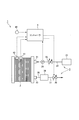
- FIG. 3 is a schematic configuration diagram of an anode gas non-circulating fuel cell system according to an embodiment of the present invention.
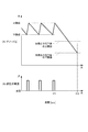
- FIG. 4 is a diagram for explaining pulsation operation during steady operation.
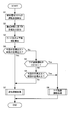
- FIG. 5 is a flowchart illustrating pulsation operation control according to an embodiment of the present invention.
- FIG. 6 is a flowchart illustrating normal operation processing according to an embodiment of the present invention.
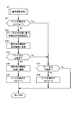
- FIG. 7 is a flowchart illustrating the down transient operation process according to the embodiment of the present invention.
- FIG. 8 is a flowchart illustrating control of the purge valve according to an embodiment of the present invention.
- FIG. 1 is a schematic perspective view of a fuel cell.
- FIG. 2 is a cross-sectional view of the fuel cell of FIG.
- FIG. 3 is a schematic configuration diagram of an anode gas non-circulating fuel
- FIG. 9 is a time chart for explaining the operation of the pulsation operation control according to the embodiment of the present invention.
- FIG. 10 is a diagram for explaining the effect of the pulsation operation control according to the embodiment of the present invention.
- FIG. 11 is a time chart showing changes in the anode pressure when the pressure regulating valve is fully closed and the anode pressure is lowered to the lower limit pressure during the lowered transient operation.
- FIG. 12 is a diagram for explaining the reason why a portion where the anode gas concentration is locally lower than the others is generated inside the anode gas flow path.
- a fuel cell has an electrolyte membrane sandwiched between an anode electrode (fuel electrode) and a cathode electrode (oxidant electrode), an anode gas containing hydrogen in the anode electrode (fuel gas), and a cathode gas containing oxygen in the cathode electrode (oxidant) Electricity is generated by supplying gas.
- the electrode reaction that proceeds in both the anode electrode and the cathode electrode is as follows.
- Anode electrode 2H 2 ⁇ 4H + + 4e ⁇ (1)
- Cathode electrode 4H + + 4e ⁇ + O 2 ⁇ 2H 2 O (2)
- the fuel cell generates an electromotive force of about 1 volt by the electrode reactions (1) and (2).
- FIG. 1 and 2 are diagrams illustrating the configuration of a fuel cell 10 according to an embodiment of the present invention.
- FIG. 1 is a schematic perspective view of the fuel cell 10.
- 2 is a cross-sectional view of the fuel cell 10 of FIG. 1 taken along the line II-II.
- the fuel cell 10 includes an anode separator 12 and a cathode separator 13 arranged on both front and back surfaces of a membrane electrode assembly (hereinafter referred to as “MEA”) 11.
- MEA membrane electrode assembly
- the MEA 11 includes an electrolyte membrane 111, an anode electrode 112, and a cathode electrode 113.
- the MEA 11 has an anode electrode 112 on one surface of the electrolyte membrane 111 and a cathode electrode 113 on the other surface.
- the electrolyte membrane 111 is a proton conductive ion exchange membrane formed of a fluorine-based resin.
- the electrolyte membrane 111 exhibits good electrical conductivity in a wet state.
- the anode electrode 112 includes a catalyst layer 112a and a gas diffusion layer 112b.
- the catalyst layer 112a is in contact with the electrolyte membrane 111.
- the catalyst layer 112a is formed of carbon black particles carrying platinum or platinum.
- the gas diffusion layer 112b is provided outside the catalyst layer 112a (on the opposite side of the electrolyte membrane 111) and is in contact with the anode separator 12.
- the gas diffusion layer 112b is formed of a member having sufficient gas diffusibility and conductivity, and is formed of, for example, a carbon cloth woven with yarns made of carbon fibers.
- the cathode electrode 113 includes a catalyst layer 113a and a gas diffusion layer 113b.
- the anode separator 12 is in contact with the gas diffusion layer 112b.
- the anode separator 12 has a plurality of groove-shaped anode gas passages 121 for supplying anode gas to the anode electrode 112 on the side in contact with the gas diffusion layer 112b.
- the cathode separator 13 is in contact with the gas diffusion layer 113b.
- the cathode separator 13 has a plurality of groove-like cathode gas flow paths 131 for supplying cathode gas to the cathode electrode 113 on the side in contact with the gas diffusion layer 113b.
- the anode gas flowing through the anode gas channel 121 and the cathode gas flowing through the cathode gas channel 131 flow in the same direction in parallel with each other. You may make it flow in the opposite direction in parallel with each other.
- FIG. 3 is a schematic configuration diagram of an anode gas non-circulating fuel cell system 1 according to an embodiment of the present invention.
- the fuel cell system 1 includes a fuel cell stack 2, an anode gas supply device 3, and a controller 4.
- the fuel cell stack 2 is formed by stacking a plurality of fuel cells 10, generates electric power by receiving supply of anode gas and cathode gas, and generates electric power necessary for driving a vehicle (for example, electric power necessary for driving a motor). ).
- the cathode gas supply / discharge device for supplying and discharging the cathode gas to / from the fuel cell stack 2 and the cooling device for cooling the fuel cell stack 2 are not the main part of the present invention, and are not shown for the sake of easy understanding. did. In this embodiment, air is used as the cathode gas.
- the anode gas supply device 3 includes a high-pressure tank 31, an anode gas supply passage 32, a pressure regulating valve 33, a pressure sensor 34, an anode gas discharge passage 35, a buffer tank 36, a purge passage 37, and a purge valve 38. .
- the high pressure tank 31 stores the anode gas supplied to the fuel cell stack 2 in a high pressure state.
- the anode gas supply passage 32 is a passage for supplying the anode gas discharged from the high-pressure tank 31 to the fuel cell stack 2, and has one end connected to the high-pressure tank 31 and the other end of the fuel cell stack 2. Connected to the anode gas inlet hole 21.
- the pressure regulating valve 33 is provided in the anode gas supply passage 32.
- the pressure regulating valve 33 adjusts the anode gas discharged from the high-pressure tank 31 to a desired pressure and supplies it to the fuel cell stack 2.
- the pressure regulating valve 33 is an electromagnetic valve whose opening degree can be adjusted continuously or stepwise, and the opening degree is controlled by the controller 4.
- the pressure sensor 34 is provided in the anode gas supply passage 32 downstream of the pressure regulating valve 33.
- the pressure sensor 34 detects the pressure of the anode gas flowing through the anode gas supply passage 32 downstream of the pressure regulating valve 33.
- the pressure of the anode gas detected by the pressure sensor 34 is the pressure of the entire anode system including the anode gas flow paths 121 and the buffer tanks 36 inside the fuel cell stack (hereinafter referred to as “anode pressure”). As a substitute.
- the anode gas discharge passage 35 has one end connected to the anode gas outlet hole 22 of the fuel cell stack 2 and the other end connected to the upper portion of the buffer tank 36.
- a mixed gas hereinafter referred to as “impure gas such as nitrogen and water vapor) cross leaked from the cathode side to the anode gas flow path 121 to the anode gas passage 121 from the cathode side.
- Anode off gas is discharged.
- the buffer tank 36 temporarily stores the anode off gas flowing through the anode gas discharge passage 35. A part of the water vapor in the anode off gas is condensed in the buffer tank 36 to become liquid water and separated from the anode off gas.
- One end of the purge passage 37 is connected to the lower part of the buffer tank 36.
- the other end of the purge passage 37 is an open end.
- the anode off gas and liquid water stored in the buffer tank 36 are discharged from the opening end to the outside air through the purge passage 37.
- the purge valve 38 is provided in the purge passage 37.
- the purge valve 38 is an electromagnetic valve whose opening degree can be adjusted continuously or stepwise, and the opening degree is controlled by the controller 4.
- the opening of the purge valve 38 By adjusting the opening of the purge valve 38, the amount of anode off-gas discharged from the buffer tank 36 to the outside air via the purge passage 37 is adjusted, and the anode gas concentration in the buffer tank 36 is adjusted to be a certain level or less. To do. This is because if the concentration of the anode gas in the buffer tank 36 becomes too high, the amount of the anode gas discharged from the buffer tank 36 through the purge passage 37 to the outside air increases and is wasted.
- the controller 48 includes a microcomputer having a central processing unit (CPU), a read only memory (ROM), a random access memory (RAM), and an input / output interface (I / O interface).
- CPU central processing unit
- ROM read only memory
- RAM random access memory
- I / O interface input / output interface
- the controller 4 includes a current sensor 41 that detects the output current of the fuel cell stack 2 and a temperature of cooling water that cools the fuel cell stack 2 (hereinafter referred to as “cooling water temperature”). Signals for detecting the operating state of the fuel cell system 1, such as the temperature sensor 42 to detect and the accelerator stroke sensor 43 to detect the amount of depression of the accelerator pedal (hereinafter referred to as “accelerator operation amount”) are input.
- the controller 4 periodically opens and closes the pressure regulating valve 33 based on these input signals, performs pulsation operation to periodically increase and decrease the anode pressure, and adjusts the opening degree of the purge valve 38 from the buffer tank 36.
- the flow rate of the anode off gas to be discharged is adjusted, and the anode gas concentration in the buffer tank 36 is kept below a certain level.
- the fuel cell stack 2 In the case of the anode gas non-circulation type fuel cell system 1, if the anode gas continues to be supplied from the high-pressure tank 31 to the fuel cell stack 2 while the pressure regulating valve 33 is kept open, the fuel cell stack 2 is not discharged. Since the anode off gas including the used anode gas is continuously discharged from the buffer tank 36 through the purge passage 37 to the outside air, it is wasted.
- the pulsation operation is performed in which the pressure regulating valve 33 is periodically opened and closed to increase and decrease the anode pressure periodically.
- impure gas such as nitrogen or water vapor that cross leaks into the power generation region (anode gas flow path 121) in the fuel cell stack can be stored in the buffer tank 36.
- FIG. 4 is a diagram for explaining the pulsation operation during the steady operation in which the operation state of the fuel cell system 1 is constant.
- the controller 4 calculates the target output of the fuel cell stack 2 based on the operating state of the fuel cell system 1, and sets the upper limit value and the lower limit value of the anode pressure according to the target output. To do. Then, the anode pressure is periodically increased or decreased between the upper limit value and the lower limit value of the set anode pressure. The details of setting the upper limit value and the lower limit value of the anode pressure will be described later with reference to the flowchart (step S3) in FIG.
- the lower limit is set as the target pressure, and feedback control to the target pressure is performed.
- the pressure regulating valve 33 is fully closed, and the supply of the anode gas from the high-pressure tank 31 to the fuel cell stack 2 is stopped.
- the anode pressure is reduced by the amount of consumption of the anode gas.
- the pressure in the buffer tank 36 temporarily becomes higher than the pressure in the anode gas flow path 121, so that the anode gas flow path 121 extends from the buffer tank 36.
- the anode off-gas flows back into.
- the anode gas left in the anode gas channel 121 and the anode gas in the anode off-gas that has flowed back to the anode gas channel 121 are consumed over time, and the anode pressure further decreases.
- the pressure regulating valve 33 When the anode pressure reaches the lower limit at time t3, the pressure regulating valve 33 is opened in the same manner as at time t1. When the anode pressure reaches the upper limit again at time t4, the pressure regulating valve 33 is fully closed.
- FIG. 11 is a time chart showing changes in the anode pressure when only the feedback control of the anode pressure is performed during the lowered transient operation.
- the upper limit value and the lower limit pressure of the anode pressure corresponding to the decreased target output are set as shown in FIG. Is done.
- the pressure regulating valve 33 is fully closed at time t11 by feedback control as shown in FIGS. 11 (A) and 11 (B). To be. When the anode pressure is lowered to the lower limit value with the pressure regulating valve 33 fully closed (time t12), a portion where the anode gas concentration is locally lower than the others is generated inside the anode gas flow path 121. . The reason for this will be described with reference to FIG.
- FIG. 12 is a diagram for explaining the reason why a portion where the anode gas concentration is locally lower than the others is generated inside the anode gas passage 121.
- FIG. 12A is a diagram showing the flow of the anode gas and the anode off-gas in the anode gas flow path 121 when the pressure regulating valve 33 is fully closed during the down transition operation.
- FIG. 12B is a diagram showing the concentration distribution of the anode gas in the anode gas flow passage 121 as time elapses when the pressure regulating valve 33 is fully closed during the down transition operation.
- the anode gas left in the anode gas flow path 121 flows to the buffer tank 36 side by inertia.
- the pressure in the buffer tank 36 temporarily becomes higher than the pressure in the anode gas flow path 121, and thus the anode gas flow path 121 from the buffer tank 36 side.
- the anode off-gas flows backward to the bottom.
- nitrogen in the anode off-gas that is not used for the electrode reaction (1) described above accumulates in the vicinity of the stagnation point as time passes.
- an anode gas having a concentration of 100% is supplied from the high-pressure tank 31 side, but an anode off-gas having a predetermined concentration (for example, 70%) of the anode gas is supplied from the buffer tank 36 side.
- the nitrogen concentration on the buffer tank 36 side is slightly higher than the others as time passes, and as shown in FIG. 12B, the anode gas concentration in the vicinity of the stagnation point is less than the time. It will be lower than others as time passes.
- the electrode reaction of (1) and (2) described above is inhibited at that portion, and the voltage is changed to a negative voltage. There is a possibility that the fuel cell 10 may be deteriorated.
- the pressure regulating valve 33 set by the feedback control is not fully closed during the downward transition operation, but is opened to a predetermined downward transition opening degree, which will be described later, while supplying the anode gas to the fuel cell stack 2,
- the anode pressure was reduced to the lower limit pressure.
- the pulsation operation control according to this embodiment will be described.
- FIG. 5 is a flowchart for explaining the pulsation operation control according to the present embodiment performed by the controller 4.
- the controller 4 executes this routine at a predetermined calculation cycle (for example, 10 ms) during operation of the fuel cell system 1.
- step S1 the controller 4 reads the detection values of the various sensors described above and detects the operating state of the fuel cell system 1.
- step S2 the controller 4 calculates the target output of the fuel cell stack 2 based on the operating state of the fuel cell system 1.
- the target output basically increases as the accelerator operation amount increases.
- step S3 based on the target output of the fuel cell stack 2, the controller 4 calculates the upper limit value and the lower limit value of the anode pressure when the pulsation operation is performed with the target output.
- the upper limit value and lower limit value of the anode pressure are set so as to increase as the target output increases.
- the pulsation amplitude (pulsation width) is determined by the upper limit value and the lower limit value of the anode pressure.
- the upper limit value and the lower limit value of the anode pressure are set so as to keep the hydrogen partial pressure in the power generation region by pushing impure gas that cross leaks into the anode gas flow path 121 during power generation from the power generation region to the buffer tank 36 by pulsation. Is done.
- the upper limit value and the lower limit value of the anode pressure are increased according to the required output, and the pulsation width is also increased.
- the upper limit value and the lower limit value of the anode pressure may be corrected according to the cooling water temperature. Specifically, correction is performed so that the target output increases as the coolant temperature increases.
- Steps S4 to S6 are performed when the current operation state of the fuel cell system 1 is a steady operation, a transient operation during a lowering operation, or during a transient operation in which the output of the fuel cell stack 2 is increased toward the target output ( This is a step for determining whether or not it is “during transient operation”. If it is a steady operation or an up-transition operation, the process finally proceeds to step S7. If it is a down-transition operation, the process finally proceeds to step S8.
- step S4 the controller 4 determines whether or not the target output calculated this time is larger than the target output calculated last time. If the target output calculated this time is larger than the target output calculated last time, the controller 4 performs the process of step S7, and otherwise performs the process of step S5.
- step S5 the controller 4 determines whether or not the down transient operation flag f is 1.
- the initial value of the down transient operation flag f is 0, and is 1 during the down transient operation.
- the controller 4 performs the process of step S8 if the lowering transient operation flag is 1, and performs the process of step S6 if it is 0.
- step S6 the controller 4 determines whether or not the target output calculated this time is smaller than the target output calculated last time.
- the controller 4 performs the process of step S8 if the target output calculated this time is smaller than the target output calculated last time, and performs the process of step S7 otherwise.
- step S7 the controller 4 performs normal operation processing. Details of the normal operation process will be described later with reference to FIG.
- step S8 the controller 4 performs a lowered transient operation process. Details of the lowering transient operation processing will be described later with reference to FIG.
- FIG. 6 is a flowchart for explaining the normal operation process.
- the normal operation process is performed during steady operation and up-transition operation.
- the feedback control is basically based on the upper limit value and the lower limit value of the anode pressure, but in this routine, the pressure reduction control and the pressure increase control are switched by a flag.
- step S71 the controller 4 determines whether or not the anode pressure reducing flag F is 1.
- the anode pressure reducing flag F is an initial value of 0, and is set to 1 until the anode pressure reaches the upper limit pressure and then decreases to the lower limit pressure. If the anode pressure reducing flag F is 0, the controller 4 performs the process of step S72. On the other hand, if the anode pressure reducing flag F is 1, the process of step S77 is performed.
- step S72 the controller 4 sets the opening of the pressure regulating valve 33 based on the upper limit value of the anode pressure so that the anode pressure can be increased to at least the upper limit value.
- step S73 the controller 4 opens the pressure regulating valve 33 to the opening set in step S72.
- step S74 the controller 4 determines whether or not the anode pressure is equal to or higher than the upper limit value. If the anode pressure is equal to or higher than the upper limit value, the controller 4 performs the process of step S75. On the other hand, if the anode pressure is less than the upper limit value, the process of step S77 is performed.
- step S75 the controller 4 fully closes the pressure regulating valve 33.
- step S76 the controller 4 sets the anode pressure reducing flag F to 1.
- step S77 the controller 4 determines whether or not the anode pressure has become equal to or lower than the lower limit value. If the anode pressure is equal to or lower than the lower limit value, the controller 4 performs the process of step S78. On the other hand, if the anode pressure is larger than the lower limit value, the current process is terminated.
- step S78 the controller 4 sets the anode pressure reducing flag F to zero.
- FIG. 7 is a flowchart for explaining the lowered transient operation processing.
- step S81 the controller 4 sets the opening degree of the pressure regulating valve 33 to a predetermined opening degree for transition.
- the anode pressure is controlled to be the lower limit pressure after reaching the upper limit by feedback control.
- the pressure regulating valve 33 is controlled to be fully closed.
- the opening of the pressure regulating valve 33 is opened to a predetermined opening so that the position where the anode gas concentration described with reference to FIG. 12 is minimum is not generated in the power generation region of the anode gas passage 121. By supplying, the speed of decompression can be suppressed.
- the anode pressure is basically determined based on the opening of the pressure regulating valve 33 and the amount of anode gas consumed by the electrode reaction inside the fuel cell stack. Therefore, the opening for the lowering transition of the pressure regulating valve 33 is such that the amount of anode gas supplied from the high pressure tank 31 to the fuel cell stack 2 is within the fuel cell stack so that the anode pressure is lowered at least during the lowering transient operation. The amount is set to be smaller than the amount of anode gas consumed by the electrode reaction.
- the opening for transition is too large, the pressure drop rate becomes too fast. Therefore, an opening that can be quickly effective is obtained by effectively suppressing the backflow of the anode off gas from the buffer tank 36 by experiments or the like.
- the target descent speed may be determined so that the backflow can be effectively suppressed. Control similar to the above can also be realized by performing feedback control based on this target value.
- step S82 the controller 4 opens the pressure regulating valve 33 to the opening for lowering transition.
- step S83 the controller 4 determines whether or not the anode pressure has become lower than the lower limit pressure. If the anode pressure is equal to or lower than the lower limit pressure, the controller 4 performs step S84. On the other hand, if the anode pressure is greater than the lower limit pressure, the process of step S85 is performed.
- step S84 the controller 4 sets the down transient operation flag f to zero.
- step S85 the controller 4 sets the down transient operation flag f to 1.
- the valve is fully closed by normal control.
- the valve may not be fully closed as long as the opening is smaller than the opening of the pressure regulating valve 33 at the time of lowering transition.
- FIG. 8 is a flowchart for explaining the control of the purge valve 38 which is performed separately from the pulsation operation control.
- step S101 the controller 4 reads the detection values of the various sensors described above and detects the operating state of the fuel cell system 1.
- step S102 the controller 4 calculates the target output of the fuel cell stack 2 based on the operating state of the fuel cell system 1.
- step S103 the controller 4 calculates the basic discharge amount of the anode off gas based on the target output and the cooling water temperature.
- the basic discharge amount of the anode off gas is set so as to increase as the target output increases and as the cooling water temperature increases.
- step S104 the controller 4 calculates the target discharge amount by correcting the basic discharge amount of the anode off gas based on the anode pressure. As the anode pressure is lower, the target discharge amount is corrected so as to decrease. This maintains the internal pressure of the buffer tank 36 at a predetermined level or higher and makes the anode gas concentration (partial pressure) in the buffer tank lower than a predetermined level. It is necessary to keep it.
- step S105 the controller 4 controls the opening degree of the purge valve so that the anode off-gas amount discharged from the buffer tank 36 to the outside air through the purge passage 37 becomes the target discharge amount of the anode off-gas.
- FIG. 9 is a time chart for explaining the operation of the pulsation operation control according to the present embodiment.
- the step numbers of the flowchart will be described together.
- the accelerator operation amount decreases and the target output of the fuel cell stack 2 decreases at time t11
- the upper limit value and the lower limit pressure of the anode pressure corresponding to the decreased target output are set (FIG. 9A; S1). To S3).
- the target output of the fuel cell stack 2 calculated at time t11 is previously calculated and smaller than the target output of the fuel cell stack 2, and the down transient operation flag f is set to the initial value 0.
- Lowering transient operation processing is performed (No in S4, No in S5, Yes in S6, S8).
- the pressure regulating valve 33 is opened to a predetermined opening for lowering transition (FIG. 9 (B); S81, S82), and the lowering transient operation flag f is set to 1 ( No in S83, S85).
- the pressure regulating valve 33 By adjusting the pressure regulating valve 33 to the opening for transient operation during the transient transition operation, the amount of the anode gas consumed by the electrode reaction inside the fuel cell stack during the transient transition operation is smaller, but a part of the consumption amount
- the anode pressure can be reduced to the lower limit pressure while supplying the anode gas for supplementing the fuel cell stack 2 from the high-pressure tank 31 (FIG. 9A).
- the anode gas is supplied from the high-pressure tank 31 to the fuel cell stack 2 during the down transition operation. Therefore, as shown by the broken line in FIG. 9A, the time until the anode pressure is lowered to the lower limit pressure is longer than when the pressure regulating valve 33 is fully closed and the anode pressure is lowered to the lower limit pressure. . That is, in this embodiment, the absolute value of the slope of the descending line when the anode pressure is reduced to the lower limit pressure is smaller than when the pressure regulating valve 33 is fully closed and the anode pressure is reduced to the lower limit pressure. To do.
- the time (time t11 to time 12) during which the anode pressure is reduced to the lower limit pressure when the pressure regulating valve 33 is fully closed is about 10 seconds during a transitional transition such as shifting from the full output state to the idle operation. is there.
- the time (time t11 to time 13) for opening the pressure regulating valve 33 to a predetermined lowering transient opening and lowering the anode pressure to the lower limit pressure is about 20 to 30 seconds.
- the scale is changed due to space limitations.
- the target output is constant until time t13 when the anode pressure reaches the lower limit pressure. However, since the down transient operation flag f is set to 1, the down transient operation process is continued (No in S4). , S5 Yes, S8).
- FIG. 10 is a diagram for explaining the effect of the pulsation operation control according to the present embodiment.
- FIG. 10A is a diagram showing the flow of the anode gas and the anode off gas in the anode gas flow passage 121 when the pressure regulating valve 33 is opened to a predetermined opening for transient transition during the transition down operation.
- FIG. 10B shows the concentration distribution of the anode gas in the anode gas flow passage 121 as time elapses when the pressure regulating valve 33 is opened to a predetermined opening for transient transition during the transition down operation.
- FIG. 10A is a diagram showing the flow of the anode gas and the anode off gas in the anode gas flow passage 121 when the pressure regulating valve 33 is opened to a predetermined opening for transient transition during the transition down operation.
- FIG. 10B shows the concentration distribution of the anode gas in the anode gas flow passage 121 as time elapses when the pressure regulating valve 33 is opened to a predetermined opening for transient
- the pressure regulating valve 33 is opened to a predetermined opening for transition during lowering transition operation. Thereby, although the amount of the anode gas consumed by the electrode reaction inside the fuel cell stack is smaller, the anode gas for supplementing a part of the consumed amount can be supplied from the high-pressure tank 31 to the fuel cell stack 2. .
- the pressure difference generated between the anode gas flow path 121 and the buffer tank 36 can be reduced during the lowered transient operation, so that the flow rate of the anode off gas flowing back from the buffer tank 36 to the anode gas flow path 121 is reduced. Can be suppressed.
- FIG. 10 (A) it is possible to suppress the occurrence of a stagnation point where the anode gas and the anode off-gas join in the anode gas channel 121.
- FIG. 10B it is possible to suppress the occurrence of a portion where the anode gas concentration is locally lower than the others in the anode gas flow path 121, thereby suppressing deterioration of the fuel cell 10. be able to. Thereby, the reliability and durability of the fuel cell system 1 can be improved.
- the opening of the pressure regulating valve during the down transition operation is adjusted to a predetermined down transition opening, but the amount of nitrogen that cross leaks from the cathode side to the anode gas passage 121 or
- the amount of nitrogen in the buffer tank 36 may be grasped by calculation or the like according to the operating state of the fuel cell system 1, and the opening for transition may be variably adjusted according to the amount of nitrogen. That is, the slope of the descending line when the anode pressure is lowered to the lower limit pressure during the lowered transient operation may be changed according to the operating state of the fuel cell system 1.
Landscapes
- Life Sciences & Earth Sciences (AREA)
- Engineering & Computer Science (AREA)
- Manufacturing & Machinery (AREA)
- Sustainable Development (AREA)
- Sustainable Energy (AREA)
- Chemical & Material Sciences (AREA)
- Chemical Kinetics & Catalysis (AREA)
- Electrochemistry (AREA)
- General Chemical & Material Sciences (AREA)
- Fuel Cell (AREA)
Abstract
Priority Applications (5)
| Application Number | Priority Date | Filing Date | Title |
|---|---|---|---|
| US13/985,483 US20130323619A1 (en) | 2011-02-23 | 2012-02-23 | Fuel cell system |
| EP12749090.2A EP2680356A1 (fr) | 2011-02-23 | 2012-02-23 | Système de pile à combustible |
| JP2013501122A JP5704228B2 (ja) | 2011-02-23 | 2012-02-23 | 燃料電池システム |
| CA2828812A CA2828812A1 (fr) | 2011-02-23 | 2012-02-23 | Systeme de pile a combustible |
| CN2012800104086A CN103392253A (zh) | 2011-02-23 | 2012-02-23 | 燃料电池系统 |
Applications Claiming Priority (2)
| Application Number | Priority Date | Filing Date | Title |
|---|---|---|---|
| JP2011-037675 | 2011-02-23 | ||
| JP2011037675 | 2011-02-23 |
Publications (1)
| Publication Number | Publication Date |
|---|---|
| WO2012115196A1 true WO2012115196A1 (fr) | 2012-08-30 |
Family
ID=46720970
Family Applications (1)
| Application Number | Title | Priority Date | Filing Date |
|---|---|---|---|
| PCT/JP2012/054436 Ceased WO2012115196A1 (fr) | 2011-02-23 | 2012-02-23 | Système de pile à combustible |
Country Status (6)
| Country | Link |
|---|---|
| US (1) | US20130323619A1 (fr) |
| EP (1) | EP2680356A1 (fr) |
| JP (1) | JP5704228B2 (fr) |
| CN (1) | CN103392253A (fr) |
| CA (1) | CA2828812A1 (fr) |
| WO (1) | WO2012115196A1 (fr) |
Cited By (4)
| Publication number | Priority date | Publication date | Assignee | Title |
|---|---|---|---|---|
| WO2013103134A1 (fr) * | 2012-01-05 | 2013-07-11 | 日産自動車株式会社 | Système de pile à combustible |
| WO2013137017A1 (fr) * | 2012-03-13 | 2013-09-19 | 日産自動車株式会社 | Système de pile à combustible et procédé de commande pour système de pile à combustible |
| WO2014192649A1 (fr) * | 2013-05-30 | 2014-12-04 | 日産自動車株式会社 | Système de pile à combustible et procédé de commande de celui-ci |
| EP3035427A4 (fr) * | 2013-08-12 | 2016-08-17 | Nissan Motor | Système de pile à combustible et procédé de commande de système de pile à combustible |
Families Citing this family (3)
| Publication number | Priority date | Publication date | Assignee | Title |
|---|---|---|---|---|
| JP5741713B2 (ja) * | 2011-12-28 | 2015-07-01 | 日産自動車株式会社 | 燃料電池システム |
| IT202000005917A1 (it) | 2020-03-19 | 2021-09-19 | Metatron S P A | Sistema di cella a combustibile e regolatore elettronico di pressione di combustibile per tale sistema |
| CN113782789B (zh) * | 2021-08-31 | 2022-03-18 | 金华氢途科技有限公司 | 一种燃料电池系统阳极压力保护方法 |
Citations (6)
| Publication number | Priority date | Publication date | Assignee | Title |
|---|---|---|---|---|
| JP2005216519A (ja) * | 2004-01-27 | 2005-08-11 | Toyota Motor Corp | 燃料電池システム |
| JP2006120383A (ja) * | 2004-10-20 | 2006-05-11 | Equos Research Co Ltd | 燃料電池システム及び燃料ガス供給方法 |
| JP2006172933A (ja) * | 2004-12-16 | 2006-06-29 | Honda Motor Co Ltd | 燃料電池システム |
| JP2006344400A (ja) * | 2005-06-07 | 2006-12-21 | Nissan Motor Co Ltd | 燃料電池システム |
| JP2007517369A (ja) | 2003-12-31 | 2007-06-28 | ヌヴェラ・フュエル・セルズ・インコーポレーテッド | 燃料電池スタックからの水の安全なパージ |
| JP2007172971A (ja) * | 2005-12-21 | 2007-07-05 | Nissan Motor Co Ltd | 燃料電池システム |
Family Cites Families (5)
| Publication number | Priority date | Publication date | Assignee | Title |
|---|---|---|---|---|
| JP4993241B2 (ja) * | 2004-03-17 | 2012-08-08 | トヨタ自動車株式会社 | 燃料電池システム |
| US8092943B2 (en) * | 2006-04-19 | 2012-01-10 | Daimler Ag | Fuel cell system with improved fuel recirculation |
| JP2009026525A (ja) * | 2007-07-18 | 2009-02-05 | Toyota Motor Corp | 燃料電池 |
| JP5200643B2 (ja) * | 2008-04-16 | 2013-06-05 | トヨタ自動車株式会社 | 燃料電池システム |
| CN103401007B (zh) * | 2008-11-21 | 2016-01-20 | 日产自动车株式会社 | 燃料电池系统及其控制方法 |
-
2012
- 2012-02-23 WO PCT/JP2012/054436 patent/WO2012115196A1/fr not_active Ceased
- 2012-02-23 CA CA2828812A patent/CA2828812A1/fr not_active Abandoned
- 2012-02-23 EP EP12749090.2A patent/EP2680356A1/fr not_active Withdrawn
- 2012-02-23 US US13/985,483 patent/US20130323619A1/en not_active Abandoned
- 2012-02-23 JP JP2013501122A patent/JP5704228B2/ja not_active Expired - Fee Related
- 2012-02-23 CN CN2012800104086A patent/CN103392253A/zh active Pending
Patent Citations (6)
| Publication number | Priority date | Publication date | Assignee | Title |
|---|---|---|---|---|
| JP2007517369A (ja) | 2003-12-31 | 2007-06-28 | ヌヴェラ・フュエル・セルズ・インコーポレーテッド | 燃料電池スタックからの水の安全なパージ |
| JP2005216519A (ja) * | 2004-01-27 | 2005-08-11 | Toyota Motor Corp | 燃料電池システム |
| JP2006120383A (ja) * | 2004-10-20 | 2006-05-11 | Equos Research Co Ltd | 燃料電池システム及び燃料ガス供給方法 |
| JP2006172933A (ja) * | 2004-12-16 | 2006-06-29 | Honda Motor Co Ltd | 燃料電池システム |
| JP2006344400A (ja) * | 2005-06-07 | 2006-12-21 | Nissan Motor Co Ltd | 燃料電池システム |
| JP2007172971A (ja) * | 2005-12-21 | 2007-07-05 | Nissan Motor Co Ltd | 燃料電池システム |
Cited By (4)
| Publication number | Priority date | Publication date | Assignee | Title |
|---|---|---|---|---|
| WO2013103134A1 (fr) * | 2012-01-05 | 2013-07-11 | 日産自動車株式会社 | Système de pile à combustible |
| WO2013137017A1 (fr) * | 2012-03-13 | 2013-09-19 | 日産自動車株式会社 | Système de pile à combustible et procédé de commande pour système de pile à combustible |
| WO2014192649A1 (fr) * | 2013-05-30 | 2014-12-04 | 日産自動車株式会社 | Système de pile à combustible et procédé de commande de celui-ci |
| EP3035427A4 (fr) * | 2013-08-12 | 2016-08-17 | Nissan Motor | Système de pile à combustible et procédé de commande de système de pile à combustible |
Also Published As
| Publication number | Publication date |
|---|---|
| US20130323619A1 (en) | 2013-12-05 |
| JPWO2012115196A1 (ja) | 2014-07-07 |
| CA2828812A1 (fr) | 2012-08-30 |
| CN103392253A (zh) | 2013-11-13 |
| JP5704228B2 (ja) | 2015-04-22 |
| EP2680356A1 (fr) | 2014-01-01 |
Similar Documents
| Publication | Publication Date | Title |
|---|---|---|
| JP5704228B2 (ja) | 燃料電池システム | |
| US10193168B2 (en) | Fuel cell system | |
| JP5741713B2 (ja) | 燃料電池システム | |
| JP5915730B2 (ja) | 燃料電池システム及び燃料電池システムの制御方法 | |
| JP5858138B2 (ja) | 燃料電池システム及び燃料電池システムの制御方法 | |
| JP5804181B2 (ja) | 燃料電池システム及び燃料電池システムの制御方法 | |
| JP6052282B2 (ja) | 燃料電池システム | |
| WO2013180080A1 (fr) | Système de pile à combustible et son procédé de commande | |
| JP2013182688A (ja) | 燃料電池システム | |
| JP2014241260A (ja) | 燃料電池システム | |
| JP5871014B2 (ja) | 燃料電池システム | |
| JP5509728B2 (ja) | 燃料電池システム | |
| JP5858137B2 (ja) | 燃料電池システム及び燃料電池システムの制御方法 |
Legal Events
| Date | Code | Title | Description |
|---|---|---|---|
| 121 | Ep: the epo has been informed by wipo that ep was designated in this application |
Ref document number: 12749090 Country of ref document: EP Kind code of ref document: A1 |
|
| DPE1 | Request for preliminary examination filed after expiration of 19th month from priority date (pct application filed from 20040101) | ||
| ENP | Entry into the national phase |
Ref document number: 2013501122 Country of ref document: JP Kind code of ref document: A |
|
| WWE | Wipo information: entry into national phase |
Ref document number: 13985483 Country of ref document: US |
|
| ENP | Entry into the national phase |
Ref document number: 2828812 Country of ref document: CA |
|
| WWE | Wipo information: entry into national phase |
Ref document number: 2012749090 Country of ref document: EP |
|
| NENP | Non-entry into the national phase |
Ref country code: DE |