WO2012117457A1 - Débroussailleuse - Google Patents
Débroussailleuse Download PDFInfo
- Publication number
- WO2012117457A1 WO2012117457A1 PCT/JP2011/004115 JP2011004115W WO2012117457A1 WO 2012117457 A1 WO2012117457 A1 WO 2012117457A1 JP 2011004115 W JP2011004115 W JP 2011004115W WO 2012117457 A1 WO2012117457 A1 WO 2012117457A1
- Authority
- WO
- WIPO (PCT)
- Prior art keywords
- clutch
- air
- flow space
- clutch housing
- centrifugal clutch
- Prior art date
- Legal status (The legal status is an assumption and is not a legal conclusion. Google has not performed a legal analysis and makes no representation as to the accuracy of the status listed.)
- Ceased
Links
Images


Classifications
-
- F—MECHANICAL ENGINEERING; LIGHTING; HEATING; WEAPONS; BLASTING
- F02—COMBUSTION ENGINES; HOT-GAS OR COMBUSTION-PRODUCT ENGINE PLANTS
- F02B—INTERNAL-COMBUSTION PISTON ENGINES; COMBUSTION ENGINES IN GENERAL
- F02B63/00—Adaptations of engines for driving pumps, hand-held tools or electric generators; Portable combinations of engines with engine-driven devices
- F02B63/02—Adaptations of engines for driving pumps, hand-held tools or electric generators; Portable combinations of engines with engine-driven devices for hand-held tools
-
- F—MECHANICAL ENGINEERING; LIGHTING; HEATING; WEAPONS; BLASTING
- F01—MACHINES OR ENGINES IN GENERAL; ENGINE PLANTS IN GENERAL; STEAM ENGINES
- F01P—COOLING OF MACHINES OR ENGINES IN GENERAL; COOLING OF INTERNAL-COMBUSTION ENGINES
- F01P1/00—Air cooling
- F01P1/06—Arrangements for cooling other engine or machine parts
-
- F—MECHANICAL ENGINEERING; LIGHTING; HEATING; WEAPONS; BLASTING
- F01—MACHINES OR ENGINES IN GENERAL; ENGINE PLANTS IN GENERAL; STEAM ENGINES
- F01P—COOLING OF MACHINES OR ENGINES IN GENERAL; COOLING OF INTERNAL-COMBUSTION ENGINES
- F01P5/00—Pumping cooling-air or liquid coolants
- F01P5/02—Pumping cooling-air; Arrangements of cooling-air pumps, e.g. fans or blowers
- F01P5/06—Guiding or ducting air to, or from, ducted fans
Definitions
- the present invention relates to a brushcutter and particularly to an improvement in a cooling mechanism of a centrifugal clutch.
- Known brushcutters often employ an engine as a drive source.
- a drive force from the drive source is transmitted to a shaft in an operating rod via a centrifugal clutch.
- the drive force rotates an attachment such as a chip saw and a nylon cutter that is attached to an end of the shaft.
- the centrifugal clutch includes: an attachment plate coupled to a crankshaft of the engine; a clutch shoe rotatably attached to the attachment plate, the clutch shoe rotating in accordance with centrifugal force; and a clutch drum frictionally engaged with the clutch shoe that is rotated radially outward, the clutch drum being connected with a base end of the shaft.
- the drive force is transmitted via the clutch shoe and the clutch drum that are mutually frictionally engaged.
- the centrifugal clutch is disposed at an outer side of a cooling fan rotatably attached to the crankshaft and is entirely covered with a clutch housing.
- a bearing for supporting the shaft connected to the clutch drum is held within the clutch housing.
- the clutch housing is made of metal or, alternatively, made of a synthetic resin in order to reduce the weight thereof. Clutch housings made of a synthetic resin are easily affected by a friction heat generated by the friction between the clutch shoe and the clutch drum.
- the load on the shaft is increased to cause continuous slip between the clutch drum and the clutch shoe, so that the temperature of the centrifugal clutch becomes high. Consequently, on account of radiation heat from the centrifugal clutch, the clutch housing may be heated beyond a softening temperature thereof to be deformed to cause dropoff of the bearing.
- An object of the invention is to provide a brushcutter that is adapted to exhibit a sufficient rigidity of the clutch housing and efficiently cool the centrifugal clutch without complicating the structure of the cooling fan.
- a brushcutter includes: an engine; a cooling fan attached to a crankshaft of the engine; a drive shaft that has a distal end attached with an attachment; a centrifugal clutch that transmits a drive force of the engine from the crankshaft to a base end of the drive shaft; a clutch housing that covers the cooling fan and the centrifugal clutch, the clutch housing being made of a synthetic resin; and a bearing that is held inside the clutch housing, the bearing supporting a coupling shaft that couples the drive shaft and the centrifugal clutch, in which: a volute-shaped air-flow space defined including a rise wall surrounding the centrifugal clutch is provided inside the clutch housing near an outer circumference of the centrifugal clutch; and an inflow opening that lets a cooling air flowing in the volute-shaped air-flow space flow into an inner air-flow space surrounded by the rise wall and an outflow opening that lets the cooling air flowing in the inner air-flow space flow out toward the volute-shaped air-flow space are provided
- a guide that partitions the volute-shaped air-flow space to guide the cooling air into the inflow opening is provided immediately at a downstream side of the inflow opening.
- downstream side herein refers to a downstream side in a flow direction of the cooling air.
- the guide is provided by a rib extending between an inner surface of the clutch housing and the rise wall.
- the guide is provided by a part of a muffler plate disposed between an exhaust muffler attached to the engine and a cylinder of the engine.
- the outflow opening is provided at an upstream side of the inflow opening.
- upstream side herein refers to an upstream side in the flow direction of the cooling air.
- the cooling air sucked by the cooling fan flows in the volute-shaped air-flow space provided in the clutch housing.
- the cooling air flows from the inflow opening and flows through the air-flow space defined inside the rise wall, so that the centrifugal clutch housed in the air-flow space can be cooled.
- the cooling air after being cooled flows out of the outflow opening to return to the volute-shaped air-flow space.
- the centrifugal clutch can be efficiently cooled by the cooling air sucked by the cooling fan.
- a sufficient rigidity of the clutch housing can be secured.
- it is not necessary to suck the cooling air from a large number of slits in the clutch housing complicated structure of the cooling fan is not necessary.
- the guide since the guide is provided immediately at a downstream side of the inflow opening, the cooling air that is in contact with the guide can be smoothly guided to the inflow opening, so that the cooling air can be efficiently sent to the centrifugal clutch.
- the guide is not provided in a shape dedicated for guiding the cooling air.
- the formation of the guide does not complicate the structure of the clutch housing and the clutch housing can be easily provided by resin molding.
- the fourth aspect of the invention since a part of the muffler plate serves as the guide, it is not necessary to provide a guide that is dedicated for guiding the cooling air, so that the cooling air can be efficiently flowed in while the structure is kept from becoming complicated.
- the cooling air flowed through the inflow opening can be directed toward the outflow opening while circulating in the outer circumference of the centrifugal clutch. Accordingly, the centrifugal clutch can be effectively exposed in the flow of the cooling air, so that the centrifugal clutch can be efficiently cooled.
- Fig. 1 is an exploded perspective illustrating a body of a brushcutter according to a first exemplary embodiment of the invention.
- Fig. 2 illustrates an inner structure of a clutch housing of the brushcutter.
- Fig. 3 is a vertical cross section taken along III-III line in Fig. 2.
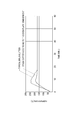
- Fig. 4 is a graph showing an effect of the invention.
- a brushcutter 1 includes: a main body 2 that includes a single-cylinder two-stroke engine 4 as a main component; an operating rod 3 having a base end connected to the body 2; an attachment (e.g. chip saw and nylon cutter) attached to another end of the operating rod 3; and a handle attached to a part of the operative rod 3.
- the engine 4 may be a four-stroke engine.
- a carburetor 5 is attached to the engine 4 and an air cleaner 6 is attached to the carburetor 5.
- An exhaust muffler 7 is attached to the engine 4 at a side opposite to the carburetor 5.
- a fuel tank 8 is attached to a lower side of the engine 4. Fuel inside the fuel tank 8 is sucked by the carburetor 5.
- the air cleaner 6 includes: a cleaner case 61 screwed to the carburetor 5; a spongelike element 62 housed in the cleaner case 61; and a cleaner cover 64 attached to the cleaner case 61 by an operating screw 63.
- a recoil starter 9 having an operating knob 91 with a drawstring is attached to an end of a crankshaft (not shown) of the engine 4.
- a cooling fan 10 having a plurality of vanes 11 and an assembly including a clutch shoe of a centrifugal clutch 20 are attached to the other end of the crankshaft.
- the centrifugal clutch 20 is attached to an outside of the cooling fan 10.
- the centrifugal clutch 20 is provided with a clutch drum 21 that is to be frictionally engaged with the clutch shoe when the clutch shoe is rotated radially outward by the centrifugal force.
- a coupling shaft 22 is attached to the clutch drum 21.
- a drive shaft 31 rotatably housed within the operating rod 3 is splined to the coupling shaft 22.
- the cooling fan 10 and the centrifugal clutch 20 are covered with a clutch housing 23 made of a synthetic resin.
- the clutch housing 23 is screwed to a fan housing 41 that is united with a crankcase of the engine 4.
- the clutch housing 23 is widened toward the body 2 to exhibit a horn shape.
- a bearing 24 that supports the coupling shaft 22 of the clutch drum 21 is held in the clutch housing 23 by insert molding or the like.
- the power of the engine 4 is transmitted from the crankshaft to the drive shaft 31 via the centrifugal clutch 20 and is transmitted to the attachment from the drive shaft 31 via an appropriate gear device provided at an end of the drive shaft 31.
- an opening 43 is provided on an opposed face 42 of the fan housing 41. Cooling air is sucked by the cooling fan 10 rotated together with the crankshaft from the opening 43 through a space between the engine 4 and the fuel tank 8 and is sent toward a cylinder 4A of the engine 4.
- the fan housing 41 provided with the opening 43 for sucking the cooling air is also provided with a first rise wall 44 that rises along an outer circumference of the fan housing 41.
- the first rise wall 44 rises in the same direction as the axial direction of the cooling fan 10 and is projected toward the cooling fan 10 relative to the opposed face 42.
- the first rise wall 44 is continuously extends on the outer circumference of the fan housing 41 from a side near the exhaust muffler 7 through a lower side of the cooling fan 10 toward the carburetor 5.
- the first rise wall 44 extends away from the outer circumference of the cooling fan 10 toward the carburetor 5.
- the above configuration of the first rise wall 44 defines a volute (spiral) shaped first air-flow space 45 between the fan housing 41 and the cooling fan 10.
- the cooling air sucked from the opening 43 flows in the first air-flow space 45 from below to the above as shown in an arrow A1 in Fig. 1 in accordance with a rotary direction of the cooling fan 10 to be guided toward the cylinder 4A at an upper position.
- An L-shaped (in plan view) muffler plate 71 for keeping the radiation heat from the exhaust muffler 7 from being transmitted to the cylinder 4A is provided between the cylinder 4A and the exhaust muffler 7.
- a part of the lower side of the muffler plate 71 partitions the first air-flow space 45 so that the cooling air is restrained from escaping through a part near the exhaust muffler 7 but is collided with the muffler plate 71 to go around the cylinder 4A.
- a second rise wall 25 that rises toward the cooling fan 10 is provided on an outer circumference of the clutch housing 23.
- a cylindrical third rise wall 26 that rises toward the cooling fan 10 is likewise provided inside the clutch housing 23.
- the third rise wall 26 surrounds the centrifugal clutch 20 and has approximately the same outer diameter as that of the cooling fan 10.
- a volute shaped second air-flow space 27 that is approximately similar to the first air-flow space 45 is defined inside the clutch housing 23 by the space between the second rise wall 25 and the third rise wall 26.
- the first air-flow space 45 and the second air-flow space 27 are mutually communicated.
- the cooling air sucked by the cooling fan 10 flows likewise in the second air-flow space 27 as shown in an arrow A2 in Figs. 2 and 3.
- a first inflow opening 28 in the shape of a cutout is provided on an upper part of the third rise wall 26 and a similar second inflow opening 29 is provided on a downstream (i.e. downstream in a flow direction of the cooling air) side of the first inflow opening 28.
- a rib 51 serving as a guide extending between an inner surface of the clutch housing 23 and the third rise wall 26 is provided immediately at a downstream of the first inflow opening 28 so as to partition the second air-flow space 27.
- the muffler plate 71 serving as a guide is located immediately at a downstream of the second inflow opening 29 so as to close the most downstream part of the second air-flow space 27.
- an outflow opening 52 in the shape of a cutout is provided at an upstream (i.e. upstream in a flow direction of the cooling air) side of the first inflow opening 28 of the third rise wall 26.
- the cooling air flowing in the second air-flow space 27 collides with the rib 51 at an upper part of the second air-flow space 27 to be guided into the third air-flow space 53 surrounded by the third rise wall 26 from the first inflow opening 28 (see an arrow A3).
- the centrifugal clutch 20 Since the centrifugal clutch 20 is housed within the third air-flow space 53, the centrifugal clutch 20 is cooled by the cooling air flowing into the third air-flow space 53 (see arrows A3 to A6). Subsequently, the cooling air returns from the outflow opening 52 to the second air-flow space 27 to flow toward the engine 4 or to enter again into the third air-flow space 53 to cool the centrifugal clutch 20.
- the centrifugal clutch 20 disposed within the third air-flow space 53 can be efficiently cooled by the cooling air.
- the deformation of the clutch housing 23 and consequent high temperature that causes dropoff of the bearing 24 can be avoided.
- Fig. 4 shows experimental results using a typical brushcutter (chain line) having no third rise wall 26 and openings 28, 29 and 52 provided on the third rise wall 26 and the brushcutter 1 (solid line) according to this exemplary embodiment.
- both of the first inflow opening 28 and the second inflow opening 29 are provided on the third rise wall 26 in the above exemplary embodiment, it is only necessary that at least one of the openings is provided on the third rise wall 26.
- the number of the openings and the opening area of each of the openings may be determined as desired in implementing the invention considering the displacement of the engine 4 and the like.
- first inflow opening 28 and the second inflow opening 29 are provided in the shape of a cutout in the above exemplary embodiment, the first inflow opening 28 and the second inflow opening 29 may be provided in an encircled configuration such as a quadrangle and a circle. In other words, the configuration of the openings may be determined as desired.
- the invention is applicable to any brushcutter irrespective of carrying types thereof such as shoulder-type and back-carrier type.
Landscapes
- Engineering & Computer Science (AREA)
- Chemical & Material Sciences (AREA)
- Combustion & Propulsion (AREA)
- Mechanical Engineering (AREA)
- General Engineering & Computer Science (AREA)
- One-Way And Automatic Clutches, And Combinations Of Different Clutches (AREA)
- Harvester Elements (AREA)
- Motor Or Generator Cooling System (AREA)
Abstract
L'invention porte sur une débroussailleuse qui comprend : un embrayage centrifuge (20) qui transmet une force motrice d'un moteur thermique d'un vilebrequin à un arbre d'entraînement ; un boîtier d'embrayage (23) qui recouvre le ventilateur de refroidissement et l'embrayage centrifuge, le boîtier d'embrayage étant fait d'une résine synthétique ; et un palier qui est tenu à l'intérieur du boîtier d'embrayage (23) et supporte un arbre d'accouplement qui accouple l'arbre d'entraînement et l'embrayage centrifuge (20). Un espace de circulation d'air (27) en forme de volute, défini en comprenant une paroi redressée (26) entourant l'embrayage centrifuge (20), est agencé à l'intérieur du boîtier d'embrayage (23) à proximité de la circonférence extérieure de l'embrayage centrifuge (20). Une ouverture d'entrée (28, 29), qui laisse un air de refroidissement qui circule dans l'espace de circulation d'air (27) pénétrer dans un espace de circulation d'air intérieur (53), et une ouverture de sortie (52) qui laisse l'air de refroidissement qui circule dans l'espace de circulation d'air (53) s'écouler dans l'espace de circulation d'air (27), sont ménagées dans la paroi redressée (26).
Priority Applications (2)
| Application Number | Priority Date | Filing Date | Title |
|---|---|---|---|
| US13/978,799 US9121339B2 (en) | 2011-02-28 | 2011-07-21 | Brushcutter |
| CN201180064958.1A CN103299045B (zh) | 2011-02-28 | 2011-07-21 | 灌丛切割机 |
Applications Claiming Priority (2)
| Application Number | Priority Date | Filing Date | Title |
|---|---|---|---|
| JP2011042213A JP5872775B2 (ja) | 2011-02-28 | 2011-02-28 | 刈払機 |
| JP2011-042213 | 2011-02-28 |
Publications (1)
| Publication Number | Publication Date |
|---|---|
| WO2012117457A1 true WO2012117457A1 (fr) | 2012-09-07 |
Family
ID=44504099
Family Applications (1)
| Application Number | Title | Priority Date | Filing Date |
|---|---|---|---|
| PCT/JP2011/004115 Ceased WO2012117457A1 (fr) | 2011-02-28 | 2011-07-21 | Débroussailleuse |
Country Status (4)
| Country | Link |
|---|---|
| US (1) | US9121339B2 (fr) |
| JP (1) | JP5872775B2 (fr) |
| CN (1) | CN103299045B (fr) |
| WO (1) | WO2012117457A1 (fr) |
Cited By (1)
| Publication number | Priority date | Publication date | Assignee | Title |
|---|---|---|---|---|
| WO2023149931A1 (fr) * | 2022-02-04 | 2023-08-10 | Warner Electric Technology Llc | Prise de force avec système de refroidissement de carter d'embrayage |
Families Citing this family (7)
| Publication number | Priority date | Publication date | Assignee | Title |
|---|---|---|---|---|
| JP1551450S (fr) * | 2015-08-28 | 2016-06-13 | ||
| KR101704276B1 (ko) | 2015-11-04 | 2017-02-08 | 현대자동차주식회사 | 차량의 클러치 구조 |
| JP1551581S (fr) * | 2015-11-25 | 2016-06-13 | ||
| JP1618969S (fr) * | 2018-01-12 | 2018-11-26 | ||
| JP1618970S (fr) * | 2018-01-12 | 2018-11-26 | ||
| WO2019187083A1 (fr) | 2018-03-30 | 2019-10-03 | 本田技研工業株式会社 | Moteur polyvalent |
| CN109185355B (zh) * | 2018-08-31 | 2024-10-29 | 南京杰泽电子科技有限公司 | 一种汽车用离合器壳 |
Citations (4)
| Publication number | Priority date | Publication date | Assignee | Title |
|---|---|---|---|---|
| US4841929A (en) * | 1987-12-17 | 1989-06-27 | White Consolidated Industries, Inc. | Portable rotary power tool |
| US20010037776A1 (en) * | 2000-05-04 | 2001-11-08 | Andreas Stihl Ag & Co. | Manually guided implement |
| US20010039736A1 (en) * | 2000-05-04 | 2001-11-15 | Andreas Stihl Ag & Co. | Manually guided implement |
| US20090113724A1 (en) * | 2007-11-07 | 2009-05-07 | Andreas Stihl Ag & Co. Kg. | Portable handheld work apparatus |
Family Cites Families (5)
| Publication number | Priority date | Publication date | Assignee | Title |
|---|---|---|---|---|
| DE10034437B4 (de) * | 2000-07-15 | 2011-07-14 | Andreas Stihl AG & Co., 71336 | Handgeführtes Arbeitsgerät |
| JP4341804B2 (ja) * | 2001-01-23 | 2009-10-14 | 本田技研工業株式会社 | 刈払機 |
| JP4349579B2 (ja) * | 2004-06-14 | 2009-10-21 | 本田技研工業株式会社 | 刈払機 |
| DE102009008055A1 (de) * | 2009-02-09 | 2010-08-12 | Andreas Stihl Ag & Co. Kg | Handgeführtes Arbeitsgerät mit einem Verbrennungsmotor |
| US8783433B2 (en) * | 2010-10-02 | 2014-07-22 | Ford Global Technologies, Llc | Dry-clutch transmission with cooling techniques |
-
2011
- 2011-02-28 JP JP2011042213A patent/JP5872775B2/ja active Active
- 2011-07-21 US US13/978,799 patent/US9121339B2/en active Active
- 2011-07-21 CN CN201180064958.1A patent/CN103299045B/zh active Active
- 2011-07-21 WO PCT/JP2011/004115 patent/WO2012117457A1/fr not_active Ceased
Patent Citations (5)
| Publication number | Priority date | Publication date | Assignee | Title |
|---|---|---|---|---|
| US4841929A (en) * | 1987-12-17 | 1989-06-27 | White Consolidated Industries, Inc. | Portable rotary power tool |
| US20010037776A1 (en) * | 2000-05-04 | 2001-11-08 | Andreas Stihl Ag & Co. | Manually guided implement |
| US20010039736A1 (en) * | 2000-05-04 | 2001-11-15 | Andreas Stihl Ag & Co. | Manually guided implement |
| JP2001355446A (ja) | 2000-05-04 | 2001-12-26 | Andreas Stihl:Fa | 手動式作業機械 |
| US20090113724A1 (en) * | 2007-11-07 | 2009-05-07 | Andreas Stihl Ag & Co. Kg. | Portable handheld work apparatus |
Cited By (2)
| Publication number | Priority date | Publication date | Assignee | Title |
|---|---|---|---|---|
| WO2023149931A1 (fr) * | 2022-02-04 | 2023-08-10 | Warner Electric Technology Llc | Prise de force avec système de refroidissement de carter d'embrayage |
| US11852200B2 (en) | 2022-02-04 | 2023-12-26 | Warner Electric Technology Llc | Power take-off with bell housing cooling system |
Also Published As
| Publication number | Publication date |
|---|---|
| CN103299045A (zh) | 2013-09-11 |
| CN103299045B (zh) | 2016-08-10 |
| JP2012178982A (ja) | 2012-09-20 |
| US9121339B2 (en) | 2015-09-01 |
| US20130284126A1 (en) | 2013-10-31 |
| JP5872775B2 (ja) | 2016-03-01 |
Similar Documents
| Publication | Publication Date | Title |
|---|---|---|
| US9121339B2 (en) | Brushcutter | |
| US9010299B2 (en) | Engine tool | |
| US6640443B2 (en) | Manually guided implement | |
| CA2920737C (fr) | Generateur entraine par un moteur | |
| EP2999097A1 (fr) | Dispositif électrique rotatif pour machine de travail à moteur | |
| US10280827B2 (en) | Engine and engine-driven working machine | |
| US4211058A (en) | Lawn mower including a carburetor enclosure | |
| JP6498482B2 (ja) | 動力作業機 | |
| EP2573352B1 (fr) | Moteur pour machine de travail portable | |
| JP6211388B2 (ja) | エンジン作業機の吸気装置 | |
| JP5527065B2 (ja) | 携帯型エンジン作業機 | |
| JP6437889B2 (ja) | マフラーカバー及びエンジン | |
| CN111148891B (zh) | 通用发动机 | |
| JP4466998B2 (ja) | 強制空冷エンジンにおける燃料タンク支持構造 | |
| EP2079919B1 (fr) | Carter et moteur à combustion interne | |
| JP4414283B2 (ja) | 強制空冷エンジン | |
| JP6631194B2 (ja) | エンジン作業機 | |
| TWI692296B (zh) | 汎用引擎 | |
| JP2015161369A (ja) | 作業機のクラッチ冷却構造 | |
| CN110557959B (zh) | 通用发动机 | |
| CN111075549B (zh) | 通用发动机 | |
| JP6296438B2 (ja) | 防塵カバー、エンジンユニット | |
| JP2020041450A (ja) | エンジン及びエンジン作業機 | |
| WO2015158842A1 (fr) | Ventilateur de véhicule | |
| JP2005344575A (ja) | 強制空冷エンジン |
Legal Events
| Date | Code | Title | Description |
|---|---|---|---|
| 121 | Ep: the epo has been informed by wipo that ep was designated in this application |
Ref document number: 11746034 Country of ref document: EP Kind code of ref document: A1 |
|
| WWE | Wipo information: entry into national phase |
Ref document number: 13978799 Country of ref document: US |
|
| NENP | Non-entry into the national phase |
Ref country code: DE |
|
| 122 | Ep: pct application non-entry in european phase |
Ref document number: 11746034 Country of ref document: EP Kind code of ref document: A1 |