WO2012117630A1 - 電気集塵装置の改造方法、電気集塵装置 - Google Patents
電気集塵装置の改造方法、電気集塵装置 Download PDFInfo
- Publication number
- WO2012117630A1 WO2012117630A1 PCT/JP2011/077247 JP2011077247W WO2012117630A1 WO 2012117630 A1 WO2012117630 A1 WO 2012117630A1 JP 2011077247 W JP2011077247 W JP 2011077247W WO 2012117630 A1 WO2012117630 A1 WO 2012117630A1
- Authority
- WO
- WIPO (PCT)
- Prior art keywords
- electrode
- casing
- electrostatic precipitator
- dust collecting
- moving
- Prior art date
- Legal status (The legal status is an assumption and is not a legal conclusion. Google has not performed a legal analysis and makes no representation as to the accuracy of the status listed.)
- Ceased
Links
Images













Classifications
-
- B—PERFORMING OPERATIONS; TRANSPORTING
- B03—SEPARATION OF SOLID MATERIALS USING LIQUIDS OR USING PNEUMATIC TABLES OR JIGS; MAGNETIC OR ELECTROSTATIC SEPARATION OF SOLID MATERIALS FROM SOLID MATERIALS OR FLUIDS; SEPARATION BY HIGH-VOLTAGE ELECTRIC FIELDS
- B03C—MAGNETIC OR ELECTROSTATIC SEPARATION OF SOLID MATERIALS FROM SOLID MATERIALS OR FLUIDS; SEPARATION BY HIGH-VOLTAGE ELECTRIC FIELDS
- B03C3/00—Separating dispersed particles from gases or vapour, e.g. air, by electrostatic effect
- B03C3/02—Plant or installations having external electricity supply
- B03C3/025—Combinations of electrostatic separators, e.g. in parallel or in series, stacked separators or dry-wet separator combinations
-
- B—PERFORMING OPERATIONS; TRANSPORTING
- B03—SEPARATION OF SOLID MATERIALS USING LIQUIDS OR USING PNEUMATIC TABLES OR JIGS; MAGNETIC OR ELECTROSTATIC SEPARATION OF SOLID MATERIALS FROM SOLID MATERIALS OR FLUIDS; SEPARATION BY HIGH-VOLTAGE ELECTRIC FIELDS
- B03C—MAGNETIC OR ELECTROSTATIC SEPARATION OF SOLID MATERIALS FROM SOLID MATERIALS OR FLUIDS; SEPARATION BY HIGH-VOLTAGE ELECTRIC FIELDS
- B03C3/00—Separating dispersed particles from gases or vapour, e.g. air, by electrostatic effect
- B03C3/02—Plant or installations having external electricity supply
- B03C3/04—Plant or installations having external electricity supply dry type
- B03C3/08—Plant or installations having external electricity supply dry type characterised by presence of stationary flat electrodes arranged with their flat surfaces parallel to the gas stream
-
- B—PERFORMING OPERATIONS; TRANSPORTING
- B03—SEPARATION OF SOLID MATERIALS USING LIQUIDS OR USING PNEUMATIC TABLES OR JIGS; MAGNETIC OR ELECTROSTATIC SEPARATION OF SOLID MATERIALS FROM SOLID MATERIALS OR FLUIDS; SEPARATION BY HIGH-VOLTAGE ELECTRIC FIELDS
- B03C—MAGNETIC OR ELECTROSTATIC SEPARATION OF SOLID MATERIALS FROM SOLID MATERIALS OR FLUIDS; SEPARATION BY HIGH-VOLTAGE ELECTRIC FIELDS
- B03C3/00—Separating dispersed particles from gases or vapour, e.g. air, by electrostatic effect
- B03C3/02—Plant or installations having external electricity supply
- B03C3/04—Plant or installations having external electricity supply dry type
- B03C3/10—Plant or installations having external electricity supply dry type characterised by presence of electrodes moving during separating action
-
- B—PERFORMING OPERATIONS; TRANSPORTING
- B03—SEPARATION OF SOLID MATERIALS USING LIQUIDS OR USING PNEUMATIC TABLES OR JIGS; MAGNETIC OR ELECTROSTATIC SEPARATION OF SOLID MATERIALS FROM SOLID MATERIALS OR FLUIDS; SEPARATION BY HIGH-VOLTAGE ELECTRIC FIELDS
- B03C—MAGNETIC OR ELECTROSTATIC SEPARATION OF SOLID MATERIALS FROM SOLID MATERIALS OR FLUIDS; SEPARATION BY HIGH-VOLTAGE ELECTRIC FIELDS
- B03C3/00—Separating dispersed particles from gases or vapour, e.g. air, by electrostatic effect
- B03C3/34—Constructional details or accessories or operation thereof
- B03C3/40—Electrode constructions
- B03C3/41—Ionising-electrodes
-
- B—PERFORMING OPERATIONS; TRANSPORTING
- B03—SEPARATION OF SOLID MATERIALS USING LIQUIDS OR USING PNEUMATIC TABLES OR JIGS; MAGNETIC OR ELECTROSTATIC SEPARATION OF SOLID MATERIALS FROM SOLID MATERIALS OR FLUIDS; SEPARATION BY HIGH-VOLTAGE ELECTRIC FIELDS
- B03C—MAGNETIC OR ELECTROSTATIC SEPARATION OF SOLID MATERIALS FROM SOLID MATERIALS OR FLUIDS; SEPARATION BY HIGH-VOLTAGE ELECTRIC FIELDS
- B03C3/00—Separating dispersed particles from gases or vapour, e.g. air, by electrostatic effect
- B03C3/34—Constructional details or accessories or operation thereof
- B03C3/40—Electrode constructions
- B03C3/45—Collecting-electrodes
- B03C3/47—Collecting-electrodes flat, e.g. plates, discs, gratings
-
- B—PERFORMING OPERATIONS; TRANSPORTING
- B03—SEPARATION OF SOLID MATERIALS USING LIQUIDS OR USING PNEUMATIC TABLES OR JIGS; MAGNETIC OR ELECTROSTATIC SEPARATION OF SOLID MATERIALS FROM SOLID MATERIALS OR FLUIDS; SEPARATION BY HIGH-VOLTAGE ELECTRIC FIELDS
- B03C—MAGNETIC OR ELECTROSTATIC SEPARATION OF SOLID MATERIALS FROM SOLID MATERIALS OR FLUIDS; SEPARATION BY HIGH-VOLTAGE ELECTRIC FIELDS
- B03C3/00—Separating dispersed particles from gases or vapour, e.g. air, by electrostatic effect
- B03C3/34—Constructional details or accessories or operation thereof
- B03C3/40—Electrode constructions
- B03C3/60—Use of special materials other than liquids
-
- B—PERFORMING OPERATIONS; TRANSPORTING
- B03—SEPARATION OF SOLID MATERIALS USING LIQUIDS OR USING PNEUMATIC TABLES OR JIGS; MAGNETIC OR ELECTROSTATIC SEPARATION OF SOLID MATERIALS FROM SOLID MATERIALS OR FLUIDS; SEPARATION BY HIGH-VOLTAGE ELECTRIC FIELDS
- B03C—MAGNETIC OR ELECTROSTATIC SEPARATION OF SOLID MATERIALS FROM SOLID MATERIALS OR FLUIDS; SEPARATION BY HIGH-VOLTAGE ELECTRIC FIELDS
- B03C3/00—Separating dispersed particles from gases or vapour, e.g. air, by electrostatic effect
- B03C3/34—Constructional details or accessories or operation thereof
- B03C3/74—Cleaning the electrodes
- B03C3/743—Cleaning the electrodes by using friction, e.g. by brushes or sliding elements
-
- B—PERFORMING OPERATIONS; TRANSPORTING
- B03—SEPARATION OF SOLID MATERIALS USING LIQUIDS OR USING PNEUMATIC TABLES OR JIGS; MAGNETIC OR ELECTROSTATIC SEPARATION OF SOLID MATERIALS FROM SOLID MATERIALS OR FLUIDS; SEPARATION BY HIGH-VOLTAGE ELECTRIC FIELDS
- B03C—MAGNETIC OR ELECTROSTATIC SEPARATION OF SOLID MATERIALS FROM SOLID MATERIALS OR FLUIDS; SEPARATION BY HIGH-VOLTAGE ELECTRIC FIELDS
- B03C3/00—Separating dispersed particles from gases or vapour, e.g. air, by electrostatic effect
- B03C3/34—Constructional details or accessories or operation thereof
- B03C3/88—Cleaning-out collected particles
-
- B—PERFORMING OPERATIONS; TRANSPORTING
- B03—SEPARATION OF SOLID MATERIALS USING LIQUIDS OR USING PNEUMATIC TABLES OR JIGS; MAGNETIC OR ELECTROSTATIC SEPARATION OF SOLID MATERIALS FROM SOLID MATERIALS OR FLUIDS; SEPARATION BY HIGH-VOLTAGE ELECTRIC FIELDS
- B03C—MAGNETIC OR ELECTROSTATIC SEPARATION OF SOLID MATERIALS FROM SOLID MATERIALS OR FLUIDS; SEPARATION BY HIGH-VOLTAGE ELECTRIC FIELDS
- B03C2201/00—Details of magnetic or electrostatic separation
- B03C2201/28—Parts being designed to be removed for cleaning purposes
Definitions
- the present invention relates to an electrostatic precipitator, and more particularly to a technique for replacing part or all of a fixed electrode electrostatic precipitator with a moving electrode electrostatic precipitator.
- the mobile electrode type electrostatic precipitator that collects soot dust by the moving dust collecting electrode has high performance for separating dust attached to the moving dust collecting electrode by the brush, and the moving dust collecting electrode is kept clean. As a result, the dust collection performance is also improved. Therefore, replacement with a moving electrode type electrostatic precipitator is effective for improving the performance of part or all of the existing fixed electrode type precipitator.
- Patent Document 1 a method of carrying in and out the fixed dust collector electrode from an opening provided on the upper side surface of the casing of the fixed electrode type precipitator is also patented.
- Document 2 discloses a method for loading and unloading a fixed dust collecting electrode from an opening from which a hopper at the lower end of a casing accommodating a fixed electrode type electrostatic dust collecting device is removed.
- Patent Document 3 the discharge electrode is carried in from the opening from which the hopper at the lower end of the casing is removed by the portal mobile crane disposed above the casing.
- a method of carrying in and attaching a moving dust collecting electrode from an opening after attachment is disclosed.
- Patent Document 4 an endless chain that constitutes a moving dust collecting electrode is attached to a driving wheel that drives a moving dust collecting electrode, and each dust collecting electrode that constitutes a moving dust collecting electrode in the vicinity of the driving wheel is attached to the endless chain.
- a method of continuous attachment is disclosed.
- Patent Document 5 one end of an endless chain is cut off, one end of a new chain is connected to one end of an endless chain, and the endless chain is moved around while the dust collecting electrode plate attached to the endless chain is sequentially replaced with the new chain.
- the new chain makes a round, remove the endless chain from which all the dust collection electrode plates have been removed, and connect one end of the new chain to the other end to replace the endless chain of the moving dust collection electrode with the new chain A method is disclosed.
- Patent Document 6 discloses a configuration in which a fixed electrode type electrostatic precipitator and a moving electrode type precipitator are arranged in a casing, and the fixed electrode type electrostatic precipitator is arranged upstream of exhaust gas passing through the casing.
- the moving electrode type electrostatic precipitator is arranged on the downstream side of the exhaust gas. Therefore, the fixed electrode type electrostatic precipitator at the front stage collects soot with a large particle size, and the rear stage movable electrode type electrostatic precipitator collects soot with a small particle size that is difficult to remove with the fixed electrode type electrostatic precipitator. be able to. Therefore, it is desirable that the fixed electrode type electrostatic precipitator be modified as shown in Patent Document 6.
- Patent Document 6 is designed so that the casing itself can appropriately arrange a fixed electrode type electrostatic precipitator and a moving electrode type precipitator. Further, in the fixed electrode type electrostatic precipitator and the moving electrode type electrostatic precipitator, not only the size (height) of the device but also the height position of the region where dust can be effectively collected from the exhaust gas is different. Therefore, in order to realize the configuration of Patent Document 6 in the conventional fixed electrode type electric dust collector, a part to which the moving electrode type electric dust collector is attached must be newly manufactured in the casing, which is costly. There is a problem.
- the present invention pays attention to the above-mentioned problem, and modifies an electric dust collector capable of replacing part or all of the fixed electrode type electrostatic dust collector with a moving electrode type electrostatic dust collector by using an existing casing as it is. It is an object to provide a method and an electrostatic precipitator formed by this method.
- a method for remodeling an electrostatic precipitator according to the present invention is, firstly, in an electrostatic precipitator in which a fixed electrode electrostatic precipitator is arranged in a casing, The dust collecting device is replaced with a moving dust collecting electrode and a discharge electrode corresponding to the moving dust collecting electrode.
- the fixed electrode type electrostatic precipitator is arranged in a plurality of stages in the direction of the flow path of the exhaust gas flowing through the casing in the casing, and a part of the fixed electrostatic precipitator or After the fixed electrostatic precipitator of all stages is removed, the moving dust collecting electrode and the discharge electrode are attached to the position where the fixed electrostatic precipitator is removed.
- the degree of remodeling of the electrostatic precipitator can be changed according to the number of fixed electrode type electrostatic precipitators to be removed and the size of the moving dust collector.
- a hopper located at a position facing the fixed electrode type electrostatic precipitator at the lower end of the casing is removed to form a lower opening, and a hoist is disposed at a position facing the lower opening of the casing The moving dust collecting electrode and the discharge electrode are lifted by the hoist and carried from the lower opening.
- the moving electrode type electric dust collecting device can be efficiently carried in even in the existing fixed electrode type electric dust collecting device in which it is difficult to secure a working space. can do.
- a housing having an insertion hole communicating with the lower opening, and the movable collection supported in the insertion hole in a state arranged in a direction perpendicular to a flow path of exhaust gas flowing through the casing.
- An upper unit having a plurality of upper rollers that support upper ends of dust electrodes is disposed at a position between the hoist and the lower opening, and is arranged so as to face the upper rollers, and the moving dust collection.
- the lower unit having a plurality of lower rollers supporting the lower ends of the electrodes is lifted by a wire that is drawn out from the hoist and inserted through the insertion hole, and is carried in from the lower opening.
- the hopper is lifted by the hoist to seal the lower opening.
- the hopper can be easily lifted and the lower opening can be easily sealed.
- the hoist is attached to a rail having a longitudinal direction in a direction perpendicular to the flow path of the exhaust gas passing through the casing at a position facing the insertion hole on the upper unit, and the hoist is moved along the rail
- the movable dust collection electrode is suspended by attaching the rail to the rail so that the movable dust collection electrode can be lifted and repeating the lifting of the new movement dust collection electrode by moving the hoist.
- a plurality of them are arranged in a direction perpendicular to the vertical axis.
- an upper opening is formed at a position facing the fixed electrode type electrostatic precipitator at the upper end of the casing, and is supported in a state arranged in a direction perpendicular to the flow path of the exhaust gas flowing through the casing.
- a lower unit having a plurality of lower rollers for supporting the lower end of the moving dust collecting electrode is carried from the upper opening and disposed in the casing, and is supported in a state of being arranged so as to face the lower roller.
- the upper unit having a plurality of upper rollers for supporting the upper end of the moving dust collecting electrode is disposed at a position facing the upper opening on the casing.
- the upper unit has an insertion hole communicating with the upper opening, the upper roller is supported in the insertion hole, and the moving dust collecting electrode is carried in from the insertion hole. And by the above method, the movable dust collecting electrode can be carried into the casing without interfering with the upper unit.
- an extension casing is disposed at a position on the casing facing the upper opening, and the upper end of the casing is extended.
- a guide plate is provided that guides the exhaust gas reaching a region lower than the lower end of the discharge electrode in the exhaust gas flow path to a position higher than the lower end of the discharge electrode.
- an electrostatic precipitator includes, firstly, a casing through which exhaust gas flows, a fixed electrode type electrostatic precipitator disposed upstream of the exhaust gas flow path in the casing, A moving dust collecting electrode that is arranged downstream of the exhaust gas flow path and that circulates in a loop by a plurality of connected dust collecting electrodes as a whole, and a discharge dust collector disposed at a position facing the moving dust collecting electrode.
- An electrode and a guide plate that is disposed in a region lower than the lower end of the discharge electrode of the exhaust gas flow path and guides the exhaust gas reaching the region to a position higher than the lower end of the discharge electrode.
- a plurality of the moving dust collecting electrodes are arranged in a direction perpendicular to the flow path, and a lower roller supporting the lower end of each moving dust collecting electrode is supported by the lower unit,
- the guide plate is attached.
- exhaust gas diffusing means is disposed between the fixed electrode type electrostatic precipitator and the movable dust collecting electrode.
- the fixed electrode type electrostatic precipitator is arranged in a plurality of stages in the direction of the flow path of the exhaust gas flowing through the casing in the casing, and the moving dust collection electrode is arranged to be the fixed electrode type electrostatic precipitator.
- the fixed electrode type electrostatic precipitator at some or all of the stages of the apparatus is attached to a removed position.
- the fixed electrode type electrostatic precipitator is arranged in a plurality of stages in the direction of the flow path of the exhaust gas flowing through the casing in the casing, and the width of the moving dust collection electrode is set to the fixed electrode type electric dust collector.
- the movable dust collecting electrode is formed wider than the dust collecting device, and the moving dust collecting electrode is attached to a position where the fixed electrode type electrostatic dust collecting devices of at least two continuous stages are removed from the fixed electrode type electric dust collecting device. It is characterized by that. With the above configuration, these can be arranged in the casing without being restricted by the width of the moving dust collection electrode.
- a diffusion space for diffusing exhaust gas is formed between the moving dust collection electrode and the fixed electrode type electrostatic precipitator, and the exhaust gas diffusion means is disposed in the diffusion space.
- the upper opening is formed at a position facing the moving dust collecting electrode at the upper end of the casing, and an extension casing is disposed at a position facing the upper opening on the casing, The upper end of the casing is extended.
- the moving dust collecting electrode can be arranged in the existing casing without being restricted by the height of the moving dust collecting electrode.
- a moving electrode type electrostatic precipitator can be disposed on the casing, and the dust collecting ability in the exhaust gas in the entire casing can be enhanced.
- the removal process of the dust collection electrode, discharge electrode, ceiling, and hopper of a fixed electrode type electrostatic dust collector in the latter stage is shown.
- the tub tube chamber attachment process is shown.
- an upper unit attachment process is shown.
- FIG. 15B is a side view of FIG. 15-b. It is a mimetic diagram showing the modification of the electric dust collector of this embodiment.
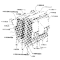
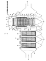
- FIG. 1 shows a perspective view of the electrostatic precipitator of this embodiment (one stage of a fixed electrode type electrostatic precipitator, one stage of a moving electrode type electrostatic precipitator).
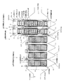
- FIG. 2 is a front view of the electrostatic precipitator of this embodiment (four stages of fixed electrode type electrostatic precipitator, two stages of moving electrode type electrostatic precipitator).
- FIG. 3 shows a partially enlarged view of the two-stage moving electrode type electrostatic precipitator in FIG. 4 shows a side view of the electrostatic precipitator of the present embodiment
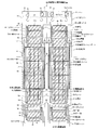
- FIG. 4-a is a side view of the fixed electrode type electrostatic precipitator
- FIG. 4-b is a side view of the moving electrode type electrostatic precipitator.
- the electrostatic precipitator is modified by the method of remodeling the electrostatic precipitator of the present embodiment.
- the electrostatic precipitator before the method of remodeling the electrostatic precipitator of the present embodiment is applied is a fixed electrode type electrostatic precipitator 28 that is all disposed in the casing.
- the main object is to replace a part (or all) of the fixed electrode type electrostatic precipitator 28 with the moving electrode type electrostatic precipitator 44.
- the modified electric dust collector 10 includes a casing 12 through which exhaust gas flows, a fixed electrode type electrostatic dust collector 28 disposed on the upstream side of the exhaust gas passage in the casing 12, and the exhaust gas passage.
- a moving dust collecting electrode 46 that is arranged on the downstream side of the dust collecting electrode plate 48 and circulates in a loop by a plurality of connected dust collecting electrode plates 48, and is arranged inside the loop and faces the moving dust collecting electrode 46.
- Discharge electrode 54 discharge electrode 55, see FIG. 14
- the exhaust gas flow path is disposed in a region lower than the lower end of the discharge electrode 54 (discharge electrode 55), and the exhaust gas reaching the region is positioned higher than the lower end of the discharge electrode 54 (discharge electrode 55).
- a guide plate 94 for guiding. Further, the position of the upper end of the casing 12 facing the moving dust collecting electrode 46 is extended in accordance with the height of the upper end of the moving dust collecting electrode 46 (upper unit 66).
- the modified electrostatic precipitator 10 (see FIG. 1) is formed on the site of a factory or the like in an overall shape formed by a casing 12, supported by a plurality of support posts 14 and floated at a constant height as a whole. Is done.
- an inlet flue 16 into which exhaust gas from a boiler or factory of a power plant flows is formed.
- an outlet flue 18 from which exhaust gas after collecting dust is discharged is formed on the opposite surface of the casing 12 facing the inlet flue 16. Therefore, the exhaust gas flow path is formed along the line connecting the inlet flue 16 and the outlet flue 18 in the casing 12.
- a pyramid-shaped hopper 20 is attached to the lower surface of the casing 12 in an array form.
- a lower opening 64 (see FIG. 6) described later is formed on the lower surface of the casing 12.
- a fixed electrode type electrostatic precipitator 28 is disposed on the upstream side of the exhaust gas flow path of the casing 12, and a moving electrode type electrostatic precipitator 44 is disposed on the downstream side.
- a large number of openings 26 are formed on the main surface between the inlet flue 16 of the casing 12 and the fixed electrode type electrostatic precipitator 28, so that a gas distribution plate 24 having a mesh structure as a whole. Is arranged so as to block the entire exhaust gas flow path.
- the gas distribution plate 24 imparts a certain resistance to the inflowing exhaust gas and causes it to flow through the opening 26 so that the exhaust gas flows uniformly in the casing so that dust can be collected efficiently.
- the fixed electrode type electrostatic precipitator 28 has a fixed dust collecting electrode 42 and a discharge electrode 30 suspended from the upper end of the casing 12.
- the fixed dust collection electrode 42 is disposed so as to be suspended from the upper end of the casing 12 and is disposed such that the normal line of the main surface thereof is perpendicular to the direction of the flue of the exhaust gas.
- a plurality of fixed dust collection electrodes 42 are arranged in a line at regular intervals in the normal direction.
- the discharge electrode 30 is arranged at a certain interval at a position where the main surface thereof faces the main surface of the fixed dust collecting electrode 42. Therefore, the discharge electrodes 30 and the fixed dust collection electrodes 42 are alternately arranged in a line in a direction perpendicular to the exhaust gas flow path.
- the discharge electrode 30 is connected to the discharge electrode frame 32 at both ends on the flow path side.
- the fixed dust collection electrode 42 is disposed at a position closest to the discharge electrode 30. Therefore, when a negative voltage is applied to the discharge electrode 30 to release negative ions from the discharge electrode 30, the released negative ions propagate toward the fixed dust collection electrode 42.
- the discharge electrode frame 32 is a member having a beam 32a having a longitudinal direction in the arrangement direction of the discharge electrodes 30, and the discharge electrode 30 is connected to the beam 32a.
- the discharge electrode frame 32 is connected to a discharge electrode frame support 34 that hangs down from the upper end of the casing 12.
- the discharge electrode frame support 34 is a rod-like member that hangs down from the lower part of the duct tube chamber 38.
- the discharge electrode frame support 34 supports the discharge electrode frame 32 in a state of penetrating a conical insulator 36 installed in the tub tube chamber 38. Therefore, the discharge electrode frame support 34 is supported by the soot tube chamber 38 via the insulator 36 and is electrically insulated from the soot tube chamber 38 (casing 12). Therefore, the discharge electrode frame support 34, the discharge electrode frame 32, and the discharge electrode 30 are electrically insulated from the casing.
- the soot tube chamber 38 is sealed and kept warm to prevent condensation on the surface of the insulator 36 and prevent leakage. Furthermore, the discharge electrode frame support 34 is electrically connected to a charging facility 40 disposed outside the casing 12.
- the fixed dust collecting electrode 42 directly connected to the casing 12 is also grounded.
- a negative high voltage is applied to the discharge electrode frame support 34 by the charging equipment 40, whereby a negative high voltage is also applied to the discharge electrode frame 32 and the discharge electrode 30. Accordingly, negative ions are released from the discharge electrode 30 in a direction intersecting the exhaust gas flow path and propagate toward the fixed dust collection electrode 42. In this state, when exhaust gas is carried in from the inlet flue 16, negative ions adhere to the dust in the exhaust gas, and the dust is negatively charged and adheres to the fixed dust collecting electrode 42, so that the dust in the exhaust gas is removed.
- the fixed dust collecting electrode 42 is beaten with a hammer (not shown), so that the dust adhering to the fixed dust collecting electrode 42 is beaten and collected at the lower end of the hopper 20, and the casing 12 passes through the discharge port 22 provided at the lower end of the hopper 20. Soot can be discharged from
- the fixed electrode type electrostatic dust collector 28 including the fixed dust collecting electrode 42, the discharge electrode 30, the discharge electrode frame 32, the discharge electrode frame support 34, and the like is arranged in a plurality of stages in the direction of the exhaust gas flow path in the casing 12. However, the number of stages is arbitrarily designed according to the specifications.
- the moving electrode type electrostatic precipitator 44 includes a moving dust collecting electrode 46, a discharge electrode 54, an upper unit 66, a lower unit 84, and the like.
- the moving dust collection electrode 46 is connected in a row via a pair of loop-shaped chains 52, and includes a plurality of dust collection electrode plates 48 that form a loop.
- the main surface of the dust collecting electrode plate 48 is arranged in parallel to the direction of the exhaust gas flow path, and connection members 50 extend from both ends of the exhaust gas flow path direction, and the connection members 50 are connected to the chain 52.
- the loop of the moving dust collecting electrode 46 forms a circular arc of the loop at the upper end and the lower end thereof, and the other part has a shape facing the vertical direction.
- a plurality of the moving dust collecting electrodes 46 are arranged at a predetermined interval in a direction perpendicular to the exhaust gas flow path, like the fixed dust collecting electrodes 42 of the fixed electrode type electrostatic dust collecting device 28.
- the discharge electrode 54 is disposed at a certain interval at a position where the main surface thereof faces the main surface of the moving dust collection electrode 46. In this case, there are a discharge electrode 54 disposed between the loops formed by the moving dust collecting electrode 46 and a discharge electrode 54 disposed between the adjacent moving dust collecting electrodes 46.
- the discharge electrode 54 and the moving dust collection electrode 46 are arranged in a line in a direction perpendicular to the flow path of the exhaust gas.
- the discharge electrode 54 is connected to the discharge electrode frame 56 at both ends on the flow path side.
- the moving dust collection electrode 46 is disposed at a position closest to the discharge electrode 54. Therefore, when a negative high voltage is applied to the discharge electrode 54 to release negative ions from the discharge electrode 54, the released negative ions propagate toward the moving dust collection electrode 46.
- the discharge electrode frame 56 is a member having a beam 56a having a longitudinal direction in the arrangement direction of the discharge electrodes 54, and the discharge electrode 54 is connected to the beam 56a.
- the discharge electrode frame 56 is connected to a discharge electrode frame support 58 that hangs down from the upper end of the casing 12.
- the discharge electrode frame support 58 is a rod-like member that hangs down from the lower part of the tub tube chamber 60.
- the discharge electrode frame support 58 supports the discharge electrode frame 56 in a state of penetrating through a conical insulator 62 installed in the tub tube chamber 60. Therefore, the discharge electrode frame support 58 is supported by the soot tube chamber 60 via the insulator 62 and is electrically insulated from the soot tube chamber 60 (casing 12). Further, the discharge electrode frame support 58 is electrically connected to a charging facility 40 or the like disposed outside the casing 12. Accordingly, the discharge electrode frame support 58, the discharge electrode frame 56, and the discharge electrode 54 are electrically insulated from the casing 12.
- soot tube chamber 60 is a room which is disposed at a position around the upper opening 100 on the casing 12 and extends along the longitudinal direction of the discharge electrode frame 56 (direction perpendicular to the flow path of the exhaust gas), An insulator 62 covering the discharge electrode frame support 58 is held inside.
- an upper opening 100 is formed at a position facing the moving dust collecting electrode 46 at the upper end of the casing 12, and the moving dust collecting electrode 46 protrudes from the upper end of the casing 12.
- the upper portion of the casing 12 is covered with an extension casing (extension member 82, soot tube chamber 60, upper unit 66, and upper cover 74) so as to cover the periphery of the upper opening 100. Therefore, the position facing the moving dust collecting electrode 46 (upper unit 66) at the upper end of the casing 12 is extended in the height direction.
- the extension member 82 is a member that extends the upper end of the casing, and has an opening that communicates with the upper opening 100 at the upper and lower ends thereof.
- the upper cover 74 has an opening at the lower end.
- the upper unit 66 is a component of the moving electrode type electrostatic precipitator 44, but is integrated with the extension casing. Therefore, the movable dust collection electrode 46 is sealed in the internal space formed by the casing 12 and the extension casing (extension member 82, soot tube chamber 60, upper unit 66, upper cover 74). Thereby, the moving electrode type electric dust collector 44 can be installed in the existing casing 12 regardless of the height of the moving dust collecting electrode 46.
- the width of the extension member 82, the soot tube chamber 60, the upper unit 66, the upper cover 74, and the lower unit 84 is substantially the same as the width of the hopper 20 in the direction of the exhaust gas flow path, but is perpendicular to the exhaust gas flow path.
- the appropriate direction is appropriately designed according to the number of moving dust collection electrodes 46 and discharge electrodes 54 arranged.
- the width of the upper opening 100 in the direction of the flow path of the exhaust gas has a dimension that does not interfere with the moving dust collection electrode 46 and the like inserted through the upper opening, and is perpendicular to the flow path of the exhaust gas in the upper opening 100. Is appropriately designed according to the number of moving dust collecting electrodes 46 and discharge electrodes 54 arranged.
- FIG. 5 shows a partial schematic diagram of the electrostatic precipitator of the present embodiment
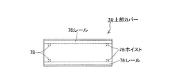
- FIG. 5-a is a plan view of an upper cover constituting the moving electrode electrostatic precipitator
- FIG. 5-b is a moving electrode electrostatic precipitator
- FIG. 5C is a plan view of the lower unit constituting the moving electrode type electrostatic precipitator.
- the upper unit 66 is disposed at a position between a hoist 78 and a lower opening 64 which will be described later.
- the outer shape of the upper unit 66 is formed by a casing 68 having an insertion hole 68 a communicating with the upper opening 100 and the lower opening 64.
- the casing 68 has a longitudinal direction in the direction in which the moving dust collection electrodes 46 are arranged.
- a plurality of upper rollers 69 (rotating shafts 70) that are supported in the insertion holes 68a and that support the upper end of the moving dust collecting electrode 46 in a state of being arranged in a direction perpendicular to the flow path of the exhaust gas flowing through the casing 12.
- Drive wheel 72 ).
- the upper roller 69 is supported by the housing 68 and is arranged in accordance with the arrangement of the moving dust collecting electrode 46, and the chain 52 is engaged with the upper end of the moving dust collecting electrode 46 (a position where a circular arc of a loop is formed). ) And a driving wheel 72 that rotates the moving dust collecting electrode 46 along the chain 52 by rotating together with the rotating shaft 70, and a motor (not shown) that rotates the rotating shaft 70.
- the rotation shaft 70 has both ends in the longitudinal direction connected to the side surface of the flow path of the insertion hole 68a. Therefore, a plurality of the upper rollers 69 are arranged in the arrangement direction of the moving dust collecting electrode 46 at a position where a circular arc of the moving dust collecting electrode 46 is formed.
- the upper cover 74 is a lid-like member whose longitudinal direction is the direction in which the moving dust collection electrodes 46 are arranged, and is disposed on the upper unit 66.
- a pair of rails 76 whose longitudinal direction is the arrangement direction of the discharge electrodes 54 are attached to the upper surface (or a side surface) of the inner wall of the upper cover 74, and at least two hoists 78 are attached to the rails 76.
- the hoist 78 can move along the longitudinal direction of the rail 76 and can lift the article to be carried in by adjusting the length of the wire 80 to be fed out.
- the rail 76 and the hoist 78 are arrange
- the lower unit 84 has a longitudinal direction in the arrangement direction of the moving dust collection electrodes 46 and is connected to the casing 12, and the lower unit 84 is arranged so as to face the upper roller 69.
- a plurality of lower rollers 87 (rotating shaft 88, lower wheel 90) supported by a body 86 and supporting the lower end of the moving dust collecting electrode.
- the lower roller 87 supports the lower end of the moving dust collecting electrode 46 (position where the arc of the loop is formed) by meshing with the rotation shaft 88 arranged following the arrangement of the moving dust collecting electrode 46 and the chain 52,
- the lower wheel 90 which rotates with the rotating shaft 88 in response to a force generated when the chain 52 loops (circulates) is provided.
- a plurality of the rotating shafts 88 are arranged so as to be directly below the rotating shaft 70 supported by the upper unit 66.
- the lower unit 84 is a cylindrical member that is supported by the casing 86 and has a longitudinal direction in a direction perpendicular to the arrangement direction of the moving dust collecting electrodes 46, and the dust collecting electrode plate 48 that constitutes the moving dust collecting electrode 46.
- the central axis of the rotary brush 92 extends to the outside of the casing 12 and is connected to a motor (not shown) that rotates the rotary brush 92 outside. Then, as shown in FIG.
- the pair of rotating brushes 92 rotate in opposite directions, and the traveling direction of the outer periphery of the rotating brush 92 on the opposite side of the pair of rotating brushes 92 is the traveling of the dust collecting electrode plate 48. It rotates so as to be opposite to each other. Therefore, the rotary brush 92 can remove the soot adhering to the surface (both sides) of the dust collecting electrode plate 48, and the removed soot is deposited on the lower end of the hopper 20 without being caught in the rotary brush 92 and the dust collecting electrode plate 48 again. Can be made.
- the moving dust collecting electrode 46 goes around with the drive wheel 72 as the upper end and the lower wheel 90 as the lower end.
- the discharge electrode 54 has a lower end disposed above the lower unit 84 and an upper end disposed below the upper unit 66 in order to prevent negative ions from propagating to portions other than the moving dust collection electrode 46. . Therefore, it is difficult to effectively remove the dust from the exhaust gas that passes from the lower end of the lower unit 84 to the height position of the lower end of the discharge electrode 54.
- the moving dust collection electrode 46 and the discharge electrode 54 may have a size higher than the dust collection electrode plate 48 of the fixed electrode type electrostatic dust collection device 28. Therefore, when the moving dust collection electrode 46 and the discharge electrode 54 are disposed in the casing 12 at the subsequent stage of the fixed electrode type electrostatic dust collector 28, the exhaust gas does not spread over the entire movement dust collection electrode 46 and the discharge electrode 54. There is.
- guide plates 94 are attached to both ends of the lower unit 84 on the exhaust gas flow path side.
- the guide plate 94 is disposed such that the lower end is connected to the hopper 20 and the upper end is substantially the same height as the lower end of the discharge electrode 54, and the exhaust gas flow path is blocked between the lower end and the upper end of the guide plate 94. Yes.
- the exhaust gas that reaches the region lower than the lower end of the discharge electrode 54 in the exhaust gas flow path can be guided to a position higher than the lower end of the discharge electrode 54. Accordingly, the exhaust gas is prevented from passing through the region below the discharge electrode 54 (discharge electrode 55, see FIG.
- the guide plate 94 and the discharge electrode 54 are not in contact with each other. Thus, since the guide plate 94 is attached to the lower unit 84, the guide plate 94 can be easily installed.
- the fixed electrode type electrostatic precipitator 28 and the moving electrode type electrostatic precipitator 44 have the same structure as the gas distribution plate 24 described above, and serve as exhaust gas diffusing means.
- An inlet distribution plate 96 is arranged so that the exhaust gas flows uniformly into the moving electrode type electrostatic precipitator 44 (moving dust collecting electrode 46, discharge electrode 54).
- an outlet distribution plate 98 having a structure similar to that of the inlet distribution plate 96 is also arranged on the downstream side of the exhaust gas of the moving electrode type electrostatic precipitator 44, and is sandwiched between the exhaust gas inlet distribution plate 96 and the outlet distribution plate 98. The flow rate in the region, that is, the portion of the exhaust gas that passes through the moving electrode type electrostatic precipitator 44 is suppressed so that dust can be efficiently collected.
- the upper unit 66 and the lower unit 84 are grounded because they are connected to the casing 12, whereby the moving dust collecting electrode 46 connected to the upper unit 66 (drive wheel 72) and the lower unit 84 (lower wheel 90) is also provided. Grounded.
- the discharge electrode 54, the discharge electrode frame 56, and the discharge electrode frame support 58 are insulated from the casing 12 and applied with a negative high voltage. Accordingly, negative ions are released from the discharge electrode 54 in a direction intersecting the exhaust gas flow path, and propagate to the dust collection electrode plate 48 constituting the moving dust collection electrode 46.
- the moving electrode type electrostatic precipitator 44 composed of the moving dust collecting electrode 46, the discharge electrode 54 and the like is arranged in a plurality of stages in the direction of the exhaust gas flow path in the casing 12, and the number of stages depends on the specification of the modification. Designed arbitrarily.
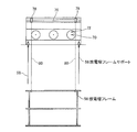
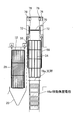
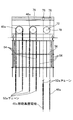
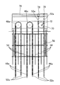
- FIG. 6 is a front view. 7 to 13
- FIG. Xa is a front view
- Fig. Xb is a side view.
- FIG. 6B the hopper 20 directly under the fixed electrode type electrostatic precipitator 28 to be removed is removed to form a lower opening 64, and the fixed electrode type electric current collector to be removed at the upper end of the casing 12 is formed.
- An upper opening 100 is formed at a position facing the dust device 28.
- the fixed electrode type electrostatic precipitator 28 is removed from the lower opening 64 or the upper opening 100 using a crane (not shown) or the like.
- the extension member 82 and the tub tube chamber 60 are lifted using a crane (not shown) or the like and attached to a position surrounding the upper opening 100 on the casing 12.
- the insulator 62 and the discharge electrode frame support 58 are attached to the soot tube chamber 60 in advance.
- an inlet distribution plate 96 (and an outlet distribution plate 98 (not shown)) may be attached.
- the upper unit 66 and the upper cover 74 are lifted using a crane (not shown) or the like and mounted on the soot tube chamber 60.
- the wire 80 is fed out from the hoist 78 attached to the upper cover 74, and the wire 80 is inserted into the insertion hole 68 a and the upper opening. Insert through the part 100. Then, the wire 80 is attached to the discharge electrode frame 56 and lifted, and the discharge electrode frame 56 is carried from the lower opening 64.
- the discharge electrode frame 56 is connected to the discharge electrode frame support 58 by welding or the like.
- the discharge electrode 54 is disposed below the lower opening 64, and as shown in FIG. 8, the wire 80 is drawn out from the hoist 78 in the same manner as described above to lift the discharge electrode 54, and the discharge electrode 54 is removed from the lower opening 64. Carry in. Then, the discharge electrode 54 is connected to the discharge electrode frame 56 by welding or the like. At this time, the operation of moving the hoist 78 appropriately on the rail 76 to lift the plurality of discharge electrodes 54 sequentially and connecting to the discharge electrode frame 56 at the lifted position is repeated.
- a pair of moving dust collecting electrodes 46a in which the chain 52 is divided into two are arranged below the lower opening 64, and as shown in FIG. 9, a balance 78a is attached to the tip of the drawn-out wire 80, The balance 78a lifts the pair of moving dust collecting electrodes 46a, and carries the pair of moving dust collecting electrodes 46a from the lower opening 64. Then, as shown in FIG. 10, the moving dust collection electrode 46 a is lifted to a height exceeding the upper end of the drive wheel 72 attached to the upper unit 66. At this time, the pair of moving dust collecting electrodes 46 are lifted to positions facing each other with the drive wheel 72 interposed therebetween.
- the hoist 78 is appropriately moved on the rail 76, the pair of moving dust collecting electrodes 46a are sequentially lifted, and the moving dust collecting electrodes 46a are connected when they are lifted.
- the moving dust collection electrode 46 discharge electrode 54
- the moving dust collection electrode 46 discharge electrode 54
- the lower unit 84 is disposed below the lower opening 64, and the lower unit 84 is lifted through the balance 78a by the hoist 78 as shown in FIG. Then, in a state where one of the pair of moving dust collecting electrodes 46a is inserted between the pair of rotating brushes 92 attached to the lower unit 84, the pair of moving dust collecting electrodes 46a face each other with the lower wheel 90 interposed therebetween. The lower unit 84 is lifted up to. Then, the chains 52a serving as the lower ends of the pair of moving dust collecting electrodes 46a are connected to form a chain 52 forming a loop and mesh with the lower wheel 90.
- the moving dust collecting electrode 46 is disposed at a position facing the discharge electrode 54 in a state where a loop is formed as a whole by the plurality of dust collecting electrode plates 48. Further, the lower unit 84 is connected to the casing 12. At this time, the guide plate 94 is previously attached to the lower unit 84 before the lower unit 84 is lifted.
- the hopper 20 removed earlier is disposed below the lower opening 64, and the hopper 20 is lifted by the hoist 78 through the balance 78a as shown in FIG. Then, as shown in FIG. 13, the remodeling process is completed by attaching the hopper 20 to the lower end of the casing 12 and sealing the lower opening 64. Although the hoist 78 remains after the remodeling, it can be used for subsequent maintenance work.
- the large moving electrode type electrostatic dust collecting device 44 can be efficiently carried into the casing 12. It can. Further, since the discharge electrode 54 and the moving dust collecting electrode 46 are lifted by the hoist 78 supported by the casing 12, the moving electrode type electrostatic dust collecting device can be efficiently used even in the existing electric dust collecting device 10 in which it is difficult to secure a work space. 44 can be modified. Similarly, the hopper 20 can be easily lifted and the upper opening 100 can be easily sealed.
- the large moving electrode type electrostatic dust collecting device 44 can be efficiently carried into the casing 12. Further, by the above method, it is possible to effectively collect the dust in the exhaust gas by preventing the exhaust gas from passing through the region below the discharge electrode 54 of the moving dust collection electrode 46 where it is difficult to collect the dust.
- a plurality of upper rollers 69 that support the moving dust collecting electrode 46 at the upper end are connected to the upper unit 66, and a plurality of lower rollers 87 that support the moving dust collecting electrode 46 at the lower end are connected to the lower unit 84.
- the upper unit 66 and the lower unit 84 are carried into the casing 12 corresponding to the position where the movable dust collection electrode 46 is installed. Accordingly, it is not necessary to examine the mounting position of each moving dust collection electrode 46 at the installation site, and the interference between the hoist 78 and the upper unit 66 can be avoided by the insertion hole 68a formed in the upper unit 66.
- a plurality of movable dust collection electrodes 46 can be easily attached.
- FIG. 14 and FIG. 15 show schematic diagrams of a modification process of the electrostatic precipitator according to the second embodiment.
- 14-a shows a process before remodeling
- FIG. 14-b shows a process of carrying in a lower unit after removing a fixed electrode type electrostatic precipitator
- FIG. 14-c shows a process of carrying in a discharge electrode frame after installing a soot tube chamber
- FIG. -D indicates the step of carrying in the discharge electrode.
- 15A shows an upper unit attaching process
- FIG. 15B shows a moving dust collecting electrode loading process (when suspended)
- FIG. 15C shows a moving dust collecting electrode loading process (just after hanging)
- FIG. -D indicates an upper cover attaching process.
- the hopper 20 is not removed, and the fixed electrode electrostatic precipitator 28 is taken out from the upper part of the casing 12 and the moving electrode electrostatic precipitator 44 is carried in.
- FIG. 14A the case where the stationary electrode type electrostatic precipitator 28 in the latter stage of the fixed electrode type electrostatic precipitator 28 is replaced with the moving electrode type electrostatic precipitator 44 also in the second embodiment will be described.
- FIG. 14B an upper opening 100 is formed at a position of the casing 12 facing the fixed electrode type electrostatic dust collector 28 to be removed, and the fixed electrode type electrostatic dust collector 28 to be removed is connected to the crane.
- the main body is lifted off (not shown) and removed from the casing 12.
- the lower unit 84 (with a guide plate 94) is lifted by a crane (main body not shown), is carried into the casing 12 from the upper opening 100, and is connected to the casing 12 at the lower portion of the casing 12.
- the extension member 82 and the tub tube chamber 60 are sequentially lifted by a crane (main body not shown) and connected to a position surrounding the upper opening 100 at the upper part of the casing 12.
- the discharge electrode frame 57 is suspended by a crane (main body not shown), the discharge electrode frame 57 is carried from the upper opening 100, and the discharge electrode frame 57 is connected to the discharge electrode frame support 58.
- the discharge electrode 55 is carried from the upper opening 100 and connected to the discharge electrode frame 57 using a crane (not shown). Since a plurality of discharge electrodes 55 are arranged in a direction perpendicular to the direction of the exhaust gas flow path, the work of carrying in and connecting the discharge electrodes 55 is performed a plurality of times according to the number of discharge electrodes 55.
- the upper unit 66 is lifted using a crane (main body not shown) and connected to the duct tube chamber 60. Then, the moving dust collecting electrode 46 is suspended through a balance using a crane (main body not shown), and the moving dust collecting electrode 46 is inserted into the insertion hole 68 a and the upper opening 100 of the upper unit 66 and is carried into the casing 12. (FIG. 15-b).
- the moving dust collecting electrode 46 is carried to a position where it is engaged with a drive wheel 72 attached to the upper unit 66, and at the same time, two chains are formed by cutting the chain 52 at the lower end when suspended. It is suspended in the casing 12 in a state where 52a is formed. Then, as shown in FIG. 15C, the chain 52 at the upper end of the moving dust collection electrode 46 is engaged with the drive wheel 72.
- discharge electrode frame 57 and the discharge electrode 55 have the same functions as the discharge electrode frame 56 and the discharge electrode 54, respectively, but when they interfere with the end portion (or the soot tube chamber 60) of the upper opening 100, The dimensional design can be changed so that it can be carried in from the upper opening 100.
- the fixed electrode type electrostatic dust collector 28 can be replaced with the moving electrode type electrostatic dust collector 44 constituted by the discharge electrode 55 and the movable dust collection electrode 46 in the existing casing 12. Since the upper unit 66 is formed with an insertion hole 68a, the movable dust collection electrode 46 can be efficiently casing without interfering with the upper unit 66 by inserting the movement dust collection electrode 46 into the insertion hole 68a. 12 can be carried in. The moving dust collection electrode 46 can be carried in efficiently.
- FIG. 17 shows a modification of the electric dust collector of this embodiment.
- the fixed electrode electrostatic precipitator 28 is arranged in a plurality of stages in the direction of the flow path of the exhaust gas flowing through the casing 12 in the casing 12.
- a part of the fixed electrode type electrostatic precipitator 28 (or all stages) may be removed, and the movable electrode type electrostatic precipitator 28 may be removed at the position where the fixed electrode type electrostatic precipitator 28 is removed.
- the apparatus 45 moving dust collection electrode and discharge electrode
- the width in the direction of the exhaust gas flow path of the moving electrode type electrostatic precipitator 44 is substantially the same as the width of the fixed electrode type electrostatic precipitator 28. Have said.
- the width of the moving electrode type electrostatic precipitator 45 may be wider than that of the fixed electrode type electrostatic precipitator 28 as in the case of the modification.
- FIG. 17 at least two continuous stages of the fixed electrode type electrostatic precipitator 28 are removed, and the moving electrode type electrostatic precipitator 45 is disposed at the removed place.
- three stages of fixed electrode type electrostatic precipitator 28 continuous along the exhaust gas flow path are removed, and the movable electrode type electric dust collector 28 is moved to the removed place.
- a dust collector 45 is provided.
- the electrostatic precipitator 10 according to the number of stages of the fixed electrostatic precipitator 28 to be removed and the dimension of the moving dust collector (moving electrode electrostatic precipitator 45) (width in the exhaust gas flow path direction). The degree of remodeling can be changed.
- the moving electrode type electrostatic precipitator 45 is not installed immediately after the fixed electrode type precipitator 28 but may form a diffusion space 102 for promoting the diffusion of exhaust gas as shown in FIG. preferable.
- the inlet distribution plate 96 is preferably disposed in the diffusion space 102. Thereby, the flow path length necessary for diffusing the exhaust gas can be secured and the exhaust gas can be effectively diffused by the inlet distribution plate 96.
- the moving electrode type electrostatic precipitator 45 shown in FIG. 17 is basically the same as the structure of the moving electrode type electric precipitator 44 described in the first and second embodiments, although the width is different. Therefore, the constituent elements indicated by the reference numerals shown in FIG. 17 are the same as the constituent elements indicated by the same reference numerals shown in FIG. Since the moving electrode type electrostatic precipitator 45 can be carried into the casing 12 by the remodeling method of the first embodiment and the second embodiment, detailed description thereof is omitted. Thereby, these can be arrange
- Remodeling that can replace the fixed electrode type electrostatic precipitator with a moving electrode type precipitator composed of a discharge electrode and a moving precipitator in an existing casing that contains the fixed electrode type precipitator. It can be used as a method and an electrostatic precipitator manufactured by using this modification method.
Landscapes
- Electrostatic Separation (AREA)
Abstract
【課題】電気集塵装置の改造方法、電気集塵装置を提供する。 【解決手段】固定電極式電気集塵装置28をケーシング12内に収容する電気集塵装置10において、前記固定電極式電気集塵装置28を、移動集塵電極46と前記移動集塵電極46に対応する放電極54に取り替える改造方法である。前記ケーシング12の下端の前記固定電極式電気集塵装置28に対向する位置にあるホッパー20を取り外して下部開口部64を形成し、前記ケーシング12の前記下部開口部64に対向する位置にホイスト78を配置し、前記固定電極式電気集塵装置28を撤去したのち、前記移動集塵電極46と前記放電極54を前記ホイスト78により吊り上げて前記下部開口部64から搬入することを特徴とする。
Description
本発明は、電気集塵装置に係り、特に固定電極式電気集塵装置の一部または全部を移動電極式電気集塵装置に置き換える技術に関する。
煤塵の排出規制値の強化や既存電気集塵装置の老朽化等により、電気集塵装置の性能を向上させることを目的とした改造・改修工事の要請がある。
このうち、固定集塵電極により煤塵を集塵する固定電極式電気集塵装置の性能向上に対しては、増設の手段が一般的となるが、既存設備に周囲に増設スペースがない場合が殆どである。
このうち、固定集塵電極により煤塵を集塵する固定電極式電気集塵装置の性能向上に対しては、増設の手段が一般的となるが、既存設備に周囲に増設スペースがない場合が殆どである。
一方、移動集塵電極により煤塵を集塵する移動電極式電気集塵装置は、ブラシにより移動集塵電極に付着した煤塵の剥離性能が高く、移動集塵電極が清浄に保たれるため、結果として集塵性能も高くなる。そのため、既設の固定電極式電気集塵装置の一部または全部を高性能化するには移動電極式電気集塵装置への置き換えが有効である。
固定電極式電気集塵装置の更新工事としては、特許文献1において、固定電極式電気集塵装置のケーシング上部側面に設けられた開口部から固定集塵電極を搬入・搬出する方法が、また特許文献2において、固定電極式電気集塵装置を収容するケーシング下端のホッパーを取り外した開口部から固定集塵電極を搬入・搬出する方法が開示されている。
一方、移動電極式電気集塵装置の設置または更新工事としては、特許文献3において、ケーシングの上方に配置した門型移動クレーンによって、ケーシング下端のホッパーを取り外した開口部から放電極を搬入して取り付けたあと、開口部から移動集塵電極を搬入して取り付ける方法が開示されている。特許文献4には、移動集塵電極を駆動する駆動ホイールに、移動集塵電極を構成する無端チェーンを取り付け、駆動ホイール近傍で移動集塵電極を構成する集塵電極を無端チェーンに一枚ずつ連続的に取り付ける方法が開示されている。特許文献5には、無端チェーンの一端を切り離すとともに新規チェーンの一端を無端チェーンの一端に接続し、無端チェーンを周回移動させながら、無端チェーンに取り付けられた集塵電極板を新規チェーンに順次付け替え、新規チェーンが一周した段階で、集塵電極板が全て取り払われた無端チェーンを取り外し、新規チェーンの一端と他端とを連結することにより、移動集塵電極の無端チェーンを新規チェーンに交換する方法が開示されている。
特許文献6には、ケーシング内に固定電極式電気集塵装置と移動電極式電気集塵装置を配置した構成が開示されており、固定電極式電気集塵装置はケーシング内を通過する排ガスの上流に配置し、移動電極式電気集塵装置は排ガスの下流側に配置している。よって前段の固定電極式電気集塵装置で粒径の大きい煤塵を捕集し、後段の移動電極式電気集塵装置で固定電極式電気集塵装置では取りにくい粒径の小さい煤塵を捕集することができる。したがって、固定電極式電気集塵装置を改修したのちは特許文献6のような構成とすることが望ましい。
しかし、特許文献6の構成は、ケーシングそのものが固定電極式電気集塵装置と、移動電極式電気集塵装置を適切に配置できるように設計されている。また固定電極式電気集塵装置と移動電極式電気集塵装置では、装置の寸法(高さ)のみならず、排ガスから煤塵を有効に捕集可能な領域の高さ位置が異なる。よって、従来の固定電極式電気集塵において特許文献6の構成を実現するためには、ケーシングのうち移動電極式電気集塵装置が取り付けられる部分を新たに製造しなければならず、コストがかかるといった問題がある。
そこで、本発明は上記問題に着目し、既存のケーシングをそのまま利用する形で固定電極式電気集塵装置の一部または全部を移動電極式電気集塵装置に置き換え可能な電気集塵装置の改造方法、及びこの方法により形成された電気集塵装置を提供することを目的とする。
上記目的を達成するため、本発明に係る電気集塵装置の改造方法は、第1には、固定電極式電気集塵装置がケーシング内に配置された電気集塵装置において、前記固定電極式電気集塵装置を、移動集塵電極と前記移動集塵電極に対応する放電極に取り替えることを特徴とする。
上記方法により、新規にケーシングを設計する必要はなく、既存の固定電極式電気集塵装置を移動集塵電極及び放電極により構成される移動電極式電気集塵装置に置き換えて、既存のケーシングを用いて排ガスの処理能力を向上させることができる。
第2には、前記固定電極式電気集塵装置は、前記ケーシング内で前記ケーシングを流通する排ガスの流路の方向に複数段配置され、前記固定式電気集塵装置のうち一部の段または全ての段の前記固定式電気集塵装置を撤去したのち、前記固定式電気集塵装置を撤去した位置に前記移動集塵電極及び前記放電極を取り付けることを特徴とする。
上記方法により、撤去対象となる固定電極式電気集塵装置の段数や移動集塵電極の寸法に応じて電気集塵装置の改造の程度を変更することができる。
第3には、前記ケーシングの下端の前記固定電極式電気集塵装置に対向する位置にあるホッパーを取り外して下部開口部を形成し、前記ケーシングの前記下部開口部に対向する位置にホイストを配置し、前記移動集塵電極と前記放電極を前記ホイストにより吊り上げて前記下部開口部から搬入することを特徴とする。
第3には、前記ケーシングの下端の前記固定電極式電気集塵装置に対向する位置にあるホッパーを取り外して下部開口部を形成し、前記ケーシングの前記下部開口部に対向する位置にホイストを配置し、前記移動集塵電極と前記放電極を前記ホイストにより吊り上げて前記下部開口部から搬入することを特徴とする。
上記方法により、移動集塵電極、放電極を、ケーシングを跨ぐように吊り上げる必要はないので、ケーシングに効率よく搬入することができる。また、ケーシングに支持されたホイストにより放電極及び移動集塵電極を吊り上げるので、作業スペースの確保が困難な既存の固定電極式電気集塵装置においても効率的に移動電極式電気集塵装置を搬入することができる。
第4には、前記下部開口部と連通する挿通孔を有する筐体と、前記ケーシング内を流通する排ガスの流路に垂直な方向に配列された状態で前記挿通孔内において支持され前記移動集塵電極の上端を支持する複数の上部ローラーと、を有する上部ユニットを、前記ホイストと前記下部開口部との間となる位置に配置し、前記上部ローラーと対向するように配列され前記移動集塵電極の下端を支持する複数の下部ローラーを有する下部ユニットを、前記ホイストから繰り出され前記挿通孔を挿通するワイヤーにより吊り上げて前記下部開口部から搬入することを特徴とする。
上記方法により、設置現場で移動集塵電極ごとに、その取り付け位置を検討する必要はなく、またホイストと上部ユニットとの干渉を回避して複数の移動集塵電極の取り付けを容易に行うことができる。
第5には、前記ホッパーを前記ホイストにより吊り上げて前記下部開口部を封止することを特徴とする。
上記方法により、ホッパーを容易に吊り上げ、下部開口部を容易に封止することができる。
上記方法により、ホッパーを容易に吊り上げ、下部開口部を容易に封止することができる。
第6には、前記上部ユニット上の前記挿通孔に対向する位置に、前記ケーシングを通過する排ガスの流路に垂直な方向に長手方向を有するレールに取り付け、前記ホイストを前記レールに沿って移動可能となるように前記レールに取り付けて前記移動集塵電極を吊り上げるとともに、前記ホイストを移動させて新たな移動集塵電極を吊り上げることを繰り返すことにより、前記移動集塵電極を前記排ガスの流路に垂直な方向に複数配列することを特徴とする。
上記方法により、作業スペースの確保が困難な既存の固定電極式電気集塵装置においても効率的に放電極を搬入可能となるとともに、効率的に移動集塵電極を複数搬入することができる。
第7には、前記ケーシングの上端の前記固定電極式電気集塵装置に対向する位置に上部開口部を形成し、前記ケーシング内を流通する排ガスの流路に垂直な方向に配列した状態で支持され、前記移動集塵電極の下端を支持する複数の下部ローラーを有する下部ユニットを前記上部開口部から搬入して前記ケーシング内に配置し、前記下部ローラーと対向するように配列した状態で支持され、前記移動集塵電極の上端を支持する複数の上部ローラーを有する上部ユニットを、前記ケーシング上の前記上部開口部に対向する位置に配置することを特徴とする。
上記方法により、設置現場で移動集塵電極ごとに、その取り付け位置を検討する必要はなく、複数の移動集塵電極の取り付けを容易に行うことができる。
上記方法により、設置現場で移動集塵電極ごとに、その取り付け位置を検討する必要はなく、複数の移動集塵電極の取り付けを容易に行うことができる。
第8には、前記上部ユニットは、前記上部開口部と連通する挿通孔を有するとともに前記上部ローラーは前記挿通孔内で支持され、前記移動集塵電極を、前記挿通孔から搬入することを特徴とする。
上記方法により、上部ユニットと干渉することなく移動集塵電極をケーシングに搬入することができる。
上記方法により、上部ユニットと干渉することなく移動集塵電極をケーシングに搬入することができる。
第9には、前記ケーシング上の前記上部開口部に対向する位置に延長ケーシングを配置して、前記ケーシングの上端を延長させたことを特徴とする。
上記方法により、移動集塵電極の高さに拘泥されず既存のケーシングに移動集塵電極を配置することができる。
上記方法により、移動集塵電極の高さに拘泥されず既存のケーシングに移動集塵電極を配置することができる。
第10には、前記排ガスの流路の前記放電極の下端より低くなる領域に到達する前記排ガスを前記放電極の下端より高くなる位置に導くガイド板を配置したことを特徴とする。
上記方法により、煤塵の捕集が困難な移動集塵電極の放電極より下の領域に排ガスが通過することを抑止して排ガス中の煤塵を有効に捕集することができる。
上記方法により、煤塵の捕集が困難な移動集塵電極の放電極より下の領域に排ガスが通過することを抑止して排ガス中の煤塵を有効に捕集することができる。
一方、本発明に係る電気集塵装置は、第1には、排ガスが流通するケーシングと、前記ケーシング内の前記排ガスの流路の上流側に配置された固定電極式電気集塵装置と、前記排ガスの流路の下流側に配置され、連結された複数枚の集塵電極によって全体としてループを形成して周回する移動集塵電極と、前記移動集塵電極に対向する位置に配置された放電極と、前記排ガスの流路の前記放電極の下端より低くなる領域に配置され、前記領域に到達する前記排ガスを前記放電極の下端より高くなる位置に導くガイド板と、を備えることを特徴とする。
上記構成により、煤塵の捕集が困難な移動集塵電極の放電極より下の領域に排ガスが通過することを抑止して排ガス中の煤塵を有効に捕集することができる。
上記構成により、煤塵の捕集が困難な移動集塵電極の放電極より下の領域に排ガスが通過することを抑止して排ガス中の煤塵を有効に捕集することができる。
第2には、前記移動集塵電極は、前記流路に垂直な方向に複数配列されるとともに、各移動集塵電極の下端を支持する下部ローラーは下部ユニットにより支持され、前記下部ユニットに、前記ガイド板を取り付けたことを特徴とする。
上記構成により、ガイド板を下部ユニットに取り付けるのでガイド板の設置を容易に行うことができる。
上記構成により、ガイド板を下部ユニットに取り付けるのでガイド板の設置を容易に行うことができる。
第3には、前記固定電極式電気集塵装置と前記移動集塵電極との間に、排ガス拡散手段が配置されたことを特徴とする。
上記構成により、移動集塵電極全体に排ガスをいきわたらせるようし、排ガスから煤塵を効率的に捕集することができる。
上記構成により、移動集塵電極全体に排ガスをいきわたらせるようし、排ガスから煤塵を効率的に捕集することができる。
第4には、前記固定電極式電気集塵装置は、前記ケーシング内で前記ケーシングを流通する排ガスの流路の方向に複数段配置され、前記移動集塵電極は、前記固定電極式電気集塵装置のうち一部の段または全ての段の前記固定電極式電気集塵装置を撤去した位置に取り付けられたことを特徴とする。
上記方法により、撤去対象となる固定電極式電気集塵装置の段数に応じて電気集塵装置の改造の程度を変更することができる。
上記方法により、撤去対象となる固定電極式電気集塵装置の段数に応じて電気集塵装置の改造の程度を変更することができる。
第5には、前記固定電極式電気集塵装置は、前記ケーシング内で前記ケーシングを流通する排ガスの流路の方向に複数段配置され、前記移動集塵電極の幅は、前記固定電極式電気集塵装置の幅より広く形成され、前記移動集塵電極は、前記固定電極式電気集塵装置のうち、少なくとも連続する2段分以上の前記固定電極式電気集塵装置を取り外した位置に取り付けられたことを特徴とする。
上記構成により、移動集塵電極の幅に拘泥されることなくこれらをケーシング内に配置することができる。
上記構成により、移動集塵電極の幅に拘泥されることなくこれらをケーシング内に配置することができる。
第6には、前記移動集塵電極と前記固定電極式電気集塵装置との間に排ガスを拡散させるための拡散空間が形成され、前記排ガス拡散手段は、前記拡散空間に配置されたことを特徴とする。
上記構成により、排ガスを拡散させるために必要な流路長を確保して排ガス拡散手段による排ガスの拡散を効果的に行なうことができる。
上記構成により、排ガスを拡散させるために必要な流路長を確保して排ガス拡散手段による排ガスの拡散を効果的に行なうことができる。
第7には、前記ケーシングの上端の前記移動集塵電極に対向する位置には前記上部開口部が形成され、前記ケーシング上の前記上部開口部に対向する位置には延長ケーシングを配置され、前記ケーシングの上端が延長されたことを特徴とする。
上記構成により、移動集塵電極の高さに拘泥されず既存のケーシングに移動集塵電極を配置することができる。
上記構成により、移動集塵電極の高さに拘泥されず既存のケーシングに移動集塵電極を配置することができる。
本発明に係る電気集塵装置の改造方法、およびこの方法により形成された電気集塵装置によれば、大きな作業スペースを確保することなく既存の固定電極式電気集塵装置が配置されたケーシング内に移動電極式電気集塵装置を配置できるとともに、ケーシング全体における排ガス中の煤塵の捕集能力を高めることができる。
以下、本発明を図に示した実施形態を用いて詳細に説明する。但し、この実施形態に記載される構成要素、種類、組み合わせ、形状、その相対配置などは特定的な記載がない限り、この発明の範囲をそれのみに限定する主旨ではなく単なる説明例に過ぎない。
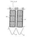
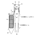
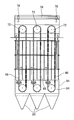
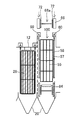
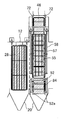
図1に、本実施形態の電気集塵装置(固定電極式電気集塵装置1段、移動電極式電気集塵装置1段)の斜視図を示す。また図2に、本実施形態の電気集塵装置(固定電極式電気集塵装置4段、移動電極式電気集塵装置2段)の正面図を示す。そして、図3に、図2の移動電極式電気集塵装置2段の部分拡大図を示す。さらに、図4に、本実施形態の電気集塵装置の側面図を示し、図4-aは固定電極式電気集塵装置の側面図、図4-bは移動電極式電気集塵装置の側面図を示す。なお、上記いずれの図も本実施形態の電気集塵装置の改造方法により改造された後の電気集塵装置となっている。
本実施形態の電気集塵装置の改造方法が適用される前の電気集塵装置は、ケーシング内に配置されたものが全て固定電極式電気集塵装置28となっているものである。そして本実施形態では、この固定電極式電気集塵装置28の一部(または全部)を移動電極式電気集塵装置44に置き換えることを主眼としている。
改造後の電気集塵装置10は、排ガスが流通するケーシング12と、前記ケーシング12内の前記排ガスの流路の上流側に配置された固定電極式電気集塵装置28と、前記排ガスの流路の下流側に配置され、連結された複数枚の集塵電極板48によって全体としてループを形成して周回する移動集塵電極46と、前記ループの内側に配置され前記移動集塵電極46に対向する放電極54(放電極55、図14参照)とを備えている。さらに前記排ガスの流路の前記放電極54(放電極55)の下端より低くなる領域に配置され、前記領域に到達する前記排ガスを前記放電極54(放電極55)の下端より高くなる位置に導くガイド板94と、を備えている。さらにケーシング12上端の前記移動集塵電極46に対向する位置は、前記移動集塵電極46(上部ユニット66)の上端の高さに合わせて延長されたものとなっている。
以下、電気集塵装置10について詳細に説明するとともに、第1実施形態の改造方法、第2実施形態の改造方法について説明する。
改造された電気集塵装置10(図1参照)は、ケーシング12により全体の外形が形成され、複数の支柱14により支持され全体的に 一定の高さで浮いた形で工場等の敷地に配置される。ケーシング12の正面には、発電所のボイラーや工場等からの排ガスが流入する入口煙道16が形成されている。またケーシング12の入口煙道16に対向する反対面には、煤塵の捕集後の排ガスが排出される出口煙道18が形成されている。よってケーシング12において入口煙道16と出口煙道18とを結ぶ線に沿って排ガスの流路が形成される。
改造された電気集塵装置10(図1参照)は、ケーシング12により全体の外形が形成され、複数の支柱14により支持され全体的に 一定の高さで浮いた形で工場等の敷地に配置される。ケーシング12の正面には、発電所のボイラーや工場等からの排ガスが流入する入口煙道16が形成されている。またケーシング12の入口煙道16に対向する反対面には、煤塵の捕集後の排ガスが排出される出口煙道18が形成されている。よってケーシング12において入口煙道16と出口煙道18とを結ぶ線に沿って排ガスの流路が形成される。
またケーシング12の下面には、角錐形状のホッパー20がアレイ状に配置された状態で取り付けられている。このホッパー20を取り外すとケーシング12下面には後述の下部開口部64(図6参照)が形成される。そして、ケーシング12の排ガスの流路の上流側には固定電極式電気集塵装置28が配置され、下流側には移動電極式電気集塵装置44が配置される。またケーシング12の入口煙道16と固定電極式電気集塵装置28との間には、その主面に開口部26が多数形成されることにより全体的にメッシュ状の構造を有するガス分布板24が排ガスの流路全体を塞ぐように配置されている。ガス分布板24は、流入する排ガスに一定の抵抗を与えて開口部26に流通させることにより、排ガスがケーシング内を均一に流れるようにし、煤塵の捕集を効率よく行なえるようにしている。
固定電極式電気集塵装置28は、ケーシング12上端から固定集塵電極42、放電極30が吊り下げられたものである。固定集塵電極42は、ケーシング12上端から吊り下げられるように配置され、その主面の法線が排ガスの煙道の方向と垂直となるように配置される。そして固定集塵電極42は、その法線方向に一定の間隔で一列に複数配列されている。
放電極30は、その主面が固定集塵電極42の主面と対向する位置に一定の間隔を置いて配置される。よって放電極30と固定集塵電極42は、排ガスの流路に垂直な方向に一列の交互に配列される。そして放電極30は、その流路側の両端で放電極フレーム32に接続される。ここで、固定集塵電極42は放電極30から最も近接した位置に配置されているものとする。よって放電極30に負の電圧を印加して放電極30から負イオンを放出させると、放出された負イオンは固定集塵電極42に向かって伝播する。
放電極フレーム32は、放電極30の配列方向に長手方向を有するビーム32aを有する部材であって、このビーム32aに放電極30が接続される。そして放電極フレーム32は、ケーシング12の上端から垂れ下がった放電極フレームサポート34に接続される。
放電極フレームサポート34は、碍管室38下部から垂れ下がった棒状の部材である。そして放電極フレームサポート34は、碍管室38に設置された円錐状の碍子36を貫通する状態で放電極フレーム32を支持する。よって、放電極フレームサポート34はこの碍子36を介して碍管室38に支持されるとともに碍管室38(ケーシング12)と電気的に絶縁される。よって放電極フレームサポート34、放電極フレーム32、放電極30はケーシングに対して電気的に絶縁される。なお碍管室38は封止されるととともに、保温することにより碍子36の表面の結露を防止し漏電を防いでいる。さらに放電極フレームサポート34はケーシング12外部に配置された荷電設備40に電気的に接続される。
ここで、ケーシング12は接地されているため、ケーシング12に直接的に接続する固定集塵電極42も接地される。一方、放電極フレームサポート34は荷電設備40により負の高電圧が印加され、これにより、放電極フレーム32、放電極30も負の高電圧が印加される。したがって、放電極30から負イオンが排ガスの流路に交差する方向に放出され固定集塵電極42に向かって伝播する。この状態で、入口煙道16から排ガスを搬入すると、排ガス中の煤塵に負イオンが付着し、煤塵が負に帯電して固定集塵電極42に付着することにより、排ガス中の煤塵は除去される。そして固定集塵電極42をハンマー(不図示)により槌打することにより固定集塵電極42に付着した煤塵を叩き落してホッパー20下端に集め、ホッパー20下端に設けられた排出口22を通してケーシング12から煤塵を排出することができる。
この固定集塵電極42、放電極30、放電極フレーム32、放電極フレームサポート34等からなる固定電極式電気集塵装置28は、ケーシング12内で排ガスの流路の方向に複数段配設されるが、その段数は仕様に応じて任意に設計される。
移動電極式電気集塵装置44は、移動集塵電極46、放電極54、上部ユニット66、下部ユニット84等を有する。移動集塵電極46は、一対のループ状のチェーン52を介して一列に連結され、ループを形成する複数の集塵電極板48により構成されている。集塵電極板48は、その主面が排ガスの流路の方向に平行に配置され、排ガスの流路の方向の両端からは接続部材50が延出され、この接続部材50がチェーン52に接続されている。移動集塵電極46のループは、その上端と下端においてループの円弧を形成し、それ以外の部分は鉛直方向を向くような形状を有している。この移動集塵電極46は、固定電極式電気集塵装置28の固定集塵電極42と同様に排ガスの流路に垂直な方向に所定の間隔で複数配列される。
放電極54は、その主面が移動集塵電極46の主面と対向する位置に一定の間隔を置いて配置される。この場合、放電極54は移動集塵電極46が形成するループの内部に配置されるものと、隣り合う移動集塵電極46との間に配置されるものがある。
よって放電極54と移動集塵電極46は、排ガスの流路に垂直な方向に一列に配列される。そして放電極54は、その流路側の両端で放電極フレーム56に接続される。ここで、移動集塵電極46は放電極54から最も近接した位置に配置されているものとする。よって放電極54に負の高電圧を印加して放電極54から負イオンを放出させると、放出された負イオンは移動集塵電極46に向かって伝播する。
放電極フレーム56は、放電極54の配列方向に長手方向を有するビーム56aを有する部材であって、このビーム56aに放電極54が接続される。そして放電極フレーム56は、ケーシング12の上端から垂れ下がった放電極フレームサポート58に接続される。
放電極フレームサポート58は、碍管室60下部から垂れ下がった棒状の部材である。そして放電極フレームサポート58は碍管室60に設置された円錐状の碍子62を貫通する状態で放電極フレーム56を支持する。よって、放電極フレームサポート58はこの碍子62を介して碍管室60に支持されるととともに碍管室60(ケーシング12)と電気的に絶縁される。また放電極フレームサポート58はケーシング12外部に配置された荷電設備40等に電気的に接続されるものとする。よって放電極フレームサポート58、放電極フレーム56、放電極54はケーシング12に対して電気的に絶縁される。なお、碍管室60は、ケーシング12上の上部開口部100の周囲となる位置に配置され、放電極フレーム56の長手方向(排ガスの流路に垂直な方向)に沿って延びる部屋であって、内部で放電極フレームサポート58を覆う碍子62を保持している。
移動集塵電極46において、その上端が固定電極式電気集塵装置28の固定集塵電極42より高く設計される場合はケーシング12の上端と干渉する。そこで、ケーシング12上端の移動集塵電極46の対向する位置には上部開口部100(図6参照)が形成され、移動集塵電極46はケーシング12の上端からはみ出る形となる。そして、ケーシング12上部には、上部開口部100の周囲を覆うように延長ケーシング(延長部材82、碍管室60、上部ユニット66、上部カバー74)により覆われる。よってケーシング12上端の移動集塵電極46(上部ユニット66)に対向する位置が高さ方向に延長された形となる。
延長部材82は、ケーシングの上端を延長する部材であって、その上端及び下端に上部開口部100と連通する開口部を有している。上部カバー74は下端に開口部を有している。また上部ユニット66は移動電極式電気集塵装置44の構成要素であるが、延長ケーシングと一体化されている。よって、移動集塵電極46はケーシング12、延長ケーシング(延長部材82、碍管室60、上部ユニット66、上部カバー74)が形成する内部空間に封止される。これにより移動集塵電極46の高さに拘泥されず既存のケーシング12に移動電極式電気集塵装置44を据付できる。
ここで、延長部材82、碍管室60、上部ユニット66、上部カバー74、下部ユニット84の幅は、ホッパー20の排ガスの流路の方向の幅とほぼ同じとなるが、排ガスの流路に垂直な方向は、移動集塵電極46、放電極54の配列する数に応じて適宜設計される。上部開口部100の排ガスの流路の方向の幅は、上部開口部に挿通する移動集塵電極46等と干渉しない程度の寸法を有し、上部開口部100の排ガスの流路に垂直な方向の幅は、移動集塵電極46、放電極54の配列する数に応じて適宜設計される。
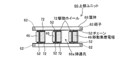
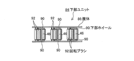
図5に、本実施形態の電気集塵装置の部分模式図を示し、図5-aは移動電極式電気集塵装置を構成する上部カバーの平面図、図5-bは移動電極式電気集塵装置を構成する上部ユニットの平面図、図5-cは移動電極式電気集塵装置を構成する下部ユニットの平面図である。
上部ユニット66は、後述のホイスト78と下部開口部64との間となる位置に配置される。上部ユニット66は、上部開口部100及び下部開口部64と連通する挿通孔68aを有する筐体68により外形が形成されている。また筐体68は、移動集塵電極46の配列方向に長手方向を有している。そして前記ケーシング12内を流通する排ガスの流路に垂直な方向に配列された状態で前記挿通孔68a内において支持され前記移動集塵電極46の上端を支持する複数の上部ローラー69(回転軸70、駆動ホイール72)を有する。
上部ローラー69は、筐体68に支持され移動集塵電極46の配列に倣って配列された回転軸70と、チェーン52と噛み合うことで移動集塵電極46の上端(ループの円弧を形成する位置)を支持するとともに、回転軸70とともに回転することで移動集塵電極46をチェーン52に沿ってループさせる駆動ホイール72と、回転軸70を回転させるモータ(不図示)と、を有する。回転軸70は、その長手方向の両端が挿通孔68aの流路の側面に接続されている。よって上部ローラー69は、移動集塵電極46のループの円弧を形成する位置において移動集塵電極46の配列方向に複数配列される。
上部カバー74は、移動集塵電極46の配列方向を長手方向とした蓋状の部材であって上部ユニット66上に配置される。また上部カバー74の内壁の上面(側面でもよい)には、放電極54の配列方向を長手方向とするレール76が一対取り付けられ、レール76には少なくとも2つ以上のホイスト78が取り付けられる。
ホイスト78はレール76の長手方向に沿って移動可能であるとともに、繰り出すワイヤー80の長さを調整することにより搬入する物品の吊り上げ等を行なうことができる。なお、レール76及びホイスト78は、ホイスト78が繰り出すワイヤー80が挿通孔68aを挿通可能となる位置に配置される。
下部ユニット84は、上部ユニット66同様に移動集塵電極46の配列方向に長手方向を有しケーシング12に接続される筐体86と、前記上部ローラー69と対向するように配列された状態で筐体86に支持され前記移動集塵電極の下端を支持する複数の下部ローラー87(回転軸88、下部ホイール90)と、を有する。
下部ローラー87は、移動集塵電極46の配列に倣って配列された回転軸88と、チェーン52と噛み合うことで移動集塵電極46の下端(ループの円弧を形成する位置)を支持するとともに、チェーン52がループ(周回運動)する際の力を受けて回転軸88とともに回転する下部ホイール90を有する。この回転軸88は、上部ユニット66に支持された回転軸70の真下に来るように複数配列される。
さらに下部ユニット84は、筐体86に支持され移動集塵電極46の配列方向に垂直な方向に長手方向を有する円柱状の部材であって、移動集塵電極46を構成する集塵電極板48を両面から挟み込むように配置された一対の回転ブラシ92を有する。回転ブラシ92は、例えばその中心軸がケーシング12外部にまで伸び、外部において回転ブラシ92を回転させるモータ(不図示)に接続される。そして図4-bに示すように、一対の回転ブラシ92は互いに逆方向に回転するとともに一対の回転ブラシ92の互いに対向する側の回転ブラシ92の外周の進行方向が集塵電極板48の進行方向とは互いに逆向きとなるように回転する。よって回転ブラシ92は集塵電極板48の表面(両面)に付着した煤塵を除去することができるとともに、除去した煤塵を再び回転ブラシ92及び集塵電極板48に巻き込むことなくホッパー20下端に堆積させることができる。
上記配置により、移動集塵電極46は駆動ホイール72を上端とし、下部ホイール90を下端として周回することになる。一方、放電極54は、移動集塵電極46以外の部分に負イオンを伝播させないようにするため、その下端は下部ユニット84より上方に配置され、その上端が上部ユニット66より下方に配置される。よって、特に下部ユニット84の下端から放電極54の下端の高さ位置を通過する排ガスからは有効に煤塵を除去することが困難となる。さらに、本実施形態のように、移動集塵電極46、放電極54は固定電極式電気集塵装置28の集塵電極板48より高い寸法を有する場合がある。よって、ケーシング12において、固定電極式電気集塵装置28の後段に移動集塵電極46、放電極54を配置する場合には、移動集塵電極46、放電極54全体に排ガスがいきわたらない場合がある。
そこで、図2、図3に示すように、下部ユニット84の排ガスの流路側の両端には、ガイド板94が取り付けられている。ガイド板94は、下端がホッパー20に接続し、上端が放電極54の下端とほぼ同じ高さとなるように配置され、ガイド板94の下端と上端との間で排ガスの流路を遮断している。これにより、排ガスの流路の放電極54の下端より低くなる領域に到達する排ガスを放電極54の下端より高くなる位置に導くことができる。よって、煤塵の捕集が困難な移動集塵電極46の放電極54(放電極55、図14参照)より下の領域に排ガスが通過することを抑止して排ガス中の煤塵を有効に捕集することができる。なお、ガイド板94と放電極54は互いに当接しないものとする。このように、ガイド板94を下部ユニット84に取り付けるのでガイド板94の設置を容易に行うことができる。
また図2に示すように、固定電極式電気集塵装置28と移動電極式電気集塵装置44との間には、前述のガス分布板24と同様の構造を有し、排ガス拡散手段となる入口分布板96が配置され、移動電極式電気集塵装置44(移動集塵電極46、放電極54)に対して排ガスが均一に流れ込むようにしている。さらに、移動電極式電気集塵装置44の排ガスの下流側にも入口分布板96と同様の構造を有する出口分布板98が配置され、排ガスの入口分布板96と出口分布板98に挟まれた領域、すなわち排ガスの移動電極式電気集塵装置44を通過する部分での流速を抑制して煤塵を効率的に捕集できるようにしている。
上記構成において、上部ユニット66、下部ユニット84はケーシング12に接続されるため接地され、これにより上部ユニット66(駆動ホイール72)及び下部ユニット84(下部ホイール90)に接続する移動集塵電極46も接地される。一方、放電極54、放電極フレーム56、放電極フレームサポート58は、ケーシング12からは絶縁され負の高電圧が印加される。したがって、放電極54から負イオンが排ガスの流路と交差する方向に放出され、移動集塵電極46を構成する集塵電極板48に伝播する。この状態で、入口煙道16から排ガスを搬入すると、固定電極式電気集塵装置28を通過した排ガス中の煤塵に負イオンが付着し、煤塵が負に帯電して集塵電極板48に付着することにより、排ガス中の煤塵は除去される。そして、煤塵が除去された排ガスは出口煙道18から排出される。
また集塵電極板48が回転ブラシ92に当接すると、集塵電極板48に付着した煤塵は、回転ブラシ92により掃き落とされホッパー20下端に蓄積する。そして、ホッパー20下端に設けられた排出口22を通してケーシング12から煤塵を排出することができる。
この移動集塵電極46、放電極54等からなる移動電極式電気集塵装置44は、ケーシング12内で排ガスの流路の方向に複数段配設されるが、その段数は改造の仕様に応じて任意に設計される。
図6乃至図13に、第1実施形態の電気集塵装置の改造工程を示す。ここで、図6は正面図である。また図7から図13において(図X-a)は正面図、(図X-b)は側面図である。
図6-aに示す固定電極式電気集塵装置のうち右側の固定電極式電気集塵装置28を移動電極式電気集塵装置44に置き換える場合について説明する。まず図6-bに示すように、撤去対象の固定電極式電気集塵装置28の真下にあるホッパー20を取り外して下部開口部64を形成し、ケーシング12上端の撤去対象の固定電極式電気集塵装置28に対向する位置に上部開口部100を形成する。そして固定電極式電気集塵装置28を下部開口部64または上部開口部100からクレーン(不図示)等を用いて撤去する。
図6-aに示す固定電極式電気集塵装置のうち右側の固定電極式電気集塵装置28を移動電極式電気集塵装置44に置き換える場合について説明する。まず図6-bに示すように、撤去対象の固定電極式電気集塵装置28の真下にあるホッパー20を取り外して下部開口部64を形成し、ケーシング12上端の撤去対象の固定電極式電気集塵装置28に対向する位置に上部開口部100を形成する。そして固定電極式電気集塵装置28を下部開口部64または上部開口部100からクレーン(不図示)等を用いて撤去する。
そして図6-cに示すように、延長部材82と碍管室60を、クレーン(不図示)等を用いて吊り上げてケーシング12上の上部開口部100を囲む位置に取り付ける。このとき碍管室60には予め碍子62と放電極フレームサポート58を取り付けておく。またこのときに入口分布板96(及び出口分布板98(不図示))を取り付けてもよい。そして図6-dに示すように上部ユニット66および上部カバー74を、クレーン(不図示)等を用いて吊り上げて碍管室60上に取り付ける。
次に、下部開口部64の下方に放電極フレーム56を配置するとともに、図7に示すように、上部カバー74に取り付けられたホイスト78からワイヤー80を繰り出し、ワイヤー80を挿通孔68a及び上部開口部100に挿通させる。そしてワイヤー80を放電極フレーム56に取り付けて吊り上げ、放電極フレーム56を下部開口部64から搬入する。そして放電極フレーム56を放電極フレームサポート58に溶接等を用いて接続する。
そして、下部開口部64の下方に放電極54を配置するとともに、図8に示すように、ホイスト78から前述同様にワイヤー80を繰り出して放電極54を吊り上げ、放電極54を下部開口部64から搬入する。そして放電極54を放電極フレーム56に溶接等を用いて接続する。このときホイスト78をレール76上で適宜移動させて複数の放電極54を順次吊り上げ、吊り上げたところで放電極フレーム56に接続する、という作業を繰り返すことになる。
次に、下部開口部64の下方にチェーン52が2つに分割された一対の移動集塵電極46aを配置するとともに、図9に示すように、繰り出したワイヤー80の先端に天秤78aを取り付け、この天秤78aにより一対の移動集塵電極46aを吊り上げて、一対の移動集塵電極46aを下部開口部64から搬入する。そして図10に示すように、移動集塵電極46aを上部ユニット66に取り付けられた駆動ホイール72の上端を越える高さまで吊り上げる。このとき一対の移動集塵電極46は、駆動ホイール72を挟んで互いに対向する位置に吊り上げられる。そして、ホイスト78からチェーン52aをはずしてチェーン52a同士を接続するとともに駆動ホイール72に噛み合わせる。このとき移動集塵電極46が駆動ホイール72から脱落しないように回転軸70の回転をロックしておく。
また、このとき、ホイスト78をレール76上で適宜移動させて一対の移動集塵電極46aを順次吊り上げ、吊り上げたところで移動集塵電極46a同士を接続する、という作業を繰り返すことになる。これにより、移動集塵電極46(放電極54)は排ガスの流路に垂直な方向に一列に配列される。
そして、下部開口部64の下方に下部ユニット84を配置するとともに、図11に示すようにホイスト78により天秤78aを介して下部ユニット84を吊り上げて、下部ユニット84を下部開口部64から搬入する。そして下部ユニット84に取り付けられた一対の回転ブラシ92の間に一対の移動集塵電極46aの一方を挿通させた状態で、一対の移動集塵電極46aが下部ホイール90を挟んで互いに対向する位置にまで下部ユニット84を吊り上げる。そして一対の移動集塵電極46aの下端となるチェーン52a同士を接続して、ループを形成するチェーン52とするとともに下部ホイール90に噛み合わせる。これにより、移動集塵電極46は、複数の集塵電極板48によって全体としてループを形成した状態で放電極54に対向する位置に配置されることになる。また下部ユニット84をケーシング12に接続する。このとき下部ユニット84の吊り上げ前にガイド板94を予め下部ユニット84に取り付けておく。
最後に、下部開口部64の下方に、先に取り外したホッパー20を配置し、図12に示すようにホイスト78により天秤78aを介してホッパー20を吊り上げる。そして図13に示すようにホッパー20をケーシング12の下端に取り付けて下部開口部64を封止することにより、改造工程は終了する。改造後にはホイスト78が残るが、以後のメンテナンス作業等に用いることができる。
上述の改造工程により、移動集塵電極46、放電極54等を、ケーシング12を跨ぐように吊り上げる必要はないので、大型の移動電極式電気集塵装置44をケーシング12に効率よく搬入することができる。また、ケーシング12に支持されたホイスト78により放電極54及び移動集塵電極46を吊り上げるので、作業スペースの確保が困難な既存の電気集塵装置10においても効率的に移動電極式電気集塵装置44に改造することができる。同様に、ホッパー20を容易に吊り上げ、上部開口部100を容易に封止することができる。
また上部カバー74にレール76上を移動可能なホイスト78を配置したことで、作業スペースの確保が困難な既存の電気集塵装置10においても効率的に放電極54、移動集塵電極46を多数搬入することができる。
また、移動集塵電極46、放電極54を、ケーシング12を跨ぐように吊り上げる必要はないので、大型の移動電極式電気集塵装置44をケーシング12に効率よく搬入することができる。また上記方法により、煤塵の捕集が困難な移動集塵電極46の放電極54より下の領域に排ガスが通過することを抑止して排ガス中の煤塵を有効に捕集することができる。
また、本実施形態では、移動集塵電極46を上端で支持する上部ローラー69を上部ユニット66に複数接続し、移動集塵電極46を下端で支持する下部ローラー87を下部ユニット84に複数接続し、上部ユニット66、下部ユニット84を、移動集塵電極46を設置する位置に対応してケーシング12に搬入している。これにより、設置現場で移動集塵電極46ごとに、その取り付け位置を検討する必要はなく、また上部ユニット66に形成された挿通孔68aにより、ホイスト78と上部ユニット66との干渉を回避して複数の移動集塵電極46の取り付けを容易に行うことができる。
なお上記改造工程は、複数ある固定電極式電気集塵装置28の一部(一段部分)を移動電極式電気集塵装置44に置き換えるものとして説明したが、複数段あるいはケーシング12内の全ての固定電極式電気集塵装置28を移動電極式電気集塵装置44に置き換える場合に適用してもよい。また、先に置き換えた移動電極式電気集塵装置44の隣に次の移動電極式電気集塵装置44を搬入する改造工程において、移動電極式電気集塵装置44同士で互いに干渉することはなく、また改造工程後においても互いに干渉することもない。したがって、複数段ある固定電極式電気集塵装置28を一段ごとに同時に移動電極式電気集塵装置44に置き換える改造も可能となり、効率的な改造が可能となる。よって撤去対象となる固定電極式電気集塵装置28の段数に応じて電気集塵装置10の改造の程度を変更することができる。
図14、図15に、第2実施形態の電気集塵装置の改造工程の模式図を示す。図14-aは改造前、図14-bは固定電極式電気集塵装置を撤去後に下部ユニットを搬入する工程、図14-cは碍管室を取り付け後に放電極フレームを搬入する工程、図14-dは放電極を搬入する工程を示す。また、図15-aは上部ユニット取り付け工程、図15-bは移動集塵電極の搬入工程(吊り降ろし時)、図15-cは移動集塵電極の搬入工程(吊り降ろし直後)、図15-dは上部カバー取り付け工程を示す。
第2実施形態の電気集塵装置の改造工程では、ホッパー20を取り外すことはなく、ケーシング12の上部から固定電極式電気集塵装置28を取り出して移動電極式電気集塵装置44を搬入する。図14-aに示すように、第2実施形態においても固定電極式電気集塵装置28のうち後段の固定電極式電気集塵装置28を移動電極式電気集塵装置44に置き換える場合について説明する。まず図14-bに示すように、ケーシング12の撤去対象の固定電極式電気集塵装置28に対向する位置に上部開口部100を形成し、撤去対象の固定電極式電気集塵装置28をクレーン(本体不図示)等で吊り上げて、ケーシング12外に撤去する。そして、クレーン(本体不図示)により下部ユニット84(ガイド板94付き)を吊り上げ、上部開口部100からケーシング12内部に搬入してケーシング12下部において、ケーシング12と接続する。
次に図14-cに示すように、クレーン(本体不図示)により延長部材82、碍管室60(放電極フレームサポート58付き)を順次吊り上げ、ケーシング12上部の上部開口部100を囲む位置に接続し、クレーン(本体不図示)により放電極フレーム57を吊り下げ、上部開口部100から放電極フレーム57を搬入し、放電極フレーム57を放電極フレームサポート58に接続する。
そして図14-dに示すように、クレーン(本体不図示)を用いて放電極55を上部開口部100から搬入し放電極フレーム57に接続する。なお放電極55は排ガスの流路の方向に垂直な方向に複数配列されるため、この放電極55を搬入及び接続する作業を放電極55の個数に応じて複数回行う。
次に図15-aに示すように、クレーン(本体不図示)を用いて上部ユニット66を吊り上げ、碍管室60上に接続する。そしてクレーン(本体不図示)を用いて天秤を介して移動集塵電極46を吊り下げ、移動集塵電極46を上部ユニット66の挿通孔68a及び上部開口部100に挿通させてケーシング12内に搬入する(図15-b)。このとき図16に示すように、移動集塵電極46は、上部ユニット66に取り付けられた駆動ホイール72に噛み合う位置に運ばれるとともに、吊り下げ時に下端となる部分のチェーン52を切断した2つのチェーン52aを形成した状態でケーシング12内に吊り降ろされる。そして図15-cに示すように移動集塵電極46の上端のチェーン52を駆動ホイール72に噛み合わせる。
最後に図15-dに示すように、チェーン52aを下部ホイール90に噛み合わせた状態で、チェーン52a同士を接続してチェーン52を形成し、クレーン(本体不図示)で上部カバー75を吊り下げて上部ユニット66の上に接続することにより改造工程は終了する。本実施形態は、ケーシング12外部にクレーン(本体不図示)を設置する場所が確保されている場合や、搬入する移動集塵電極46等が小型である場合に有効な方法となる。よって上部カバー75にレール76やホイスト78を取り付ける必要はない。また放電極フレーム57、放電極55は、それぞれ放電極フレーム56、放電極54と同様の機能を有するものであるが、上部開口部100の端部(または碍管室60)と干渉する場合は、上部開口部100から搬入できるように寸法上の設計変更を行なうことができる。
上記方法により、既存のケーシング12内において、固定電極式電気集塵装置28を放電極55と移動集塵電極46により構成される移動電極式電気集塵装置44に置き換えることができる。また上部ユニット66には挿通孔68aが形成されているため、この挿通孔68aに移動集塵電極46を挿通することで、上部ユニット66と干渉することなく移動集塵電極46を効率的にケーシング12に搬入することができる。
効率的に移動集塵電極46の搬入を行なうことができる。
効率的に移動集塵電極46の搬入を行なうことができる。
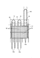
図17に本実施形態の電気集塵装置の変形例を示す。上述のように、電気集塵装置10において、前記固定電極式電気集塵装置28は、前記ケーシング12内で前記ケーシング12を流通する排ガスの流路の方向に複数段配置されている。そして本変形例では、固定電極式電気集塵装置28のうち一部の段(全ての段でも良い)を撤去し、固定電極式電気集塵装置28を撤去した位置に移動電極式電気集塵装置45(移動集塵電極及び放電極)を取り付けたものとなっている。
第1実施形態、第2実施形態においては、移動電極式電気集塵装置44の排ガスの流路の方向の幅が、固定電極式電気集塵装置28の幅とほぼ同じとなる場合を前提として述べてきた。しかし、変形例の場合のように移動電極式電気集塵装置45の幅は固定電極式電気集塵装置28より広くなる場合がある。このときは、図17に示すように固定電極式電気集塵装置28の少なくとも連続する2段分以上を撤去して、撤去した場所に移動電極式電気集塵装置45を配置している。図17においては、固定電極式電気集塵装置28のうち、排ガスの流路に沿って連続した3段分の固定電極式電気集塵装置28を撤去し、その撤去した場所に移動電極式電気集塵装置45を配置している。これにより、撤去対象となる固定式電気集塵装置28の段数や移動集塵電極(移動電極式電気集塵装置45)の寸法(排ガスの流路方向の幅)に応じて電気集塵装置10の改造の程度を変更することができる。
また移動電極式電気集塵装置45は、固定電極式電気集塵装置28の直後に設置するのではなく、図17に示すように、排ガスの拡散を促すための拡散空間102を形成することが好ましい。そして、この拡散空間102に上述の入口分布板96を配置することが好ましい。これにより、排ガスを拡散させるために必要な流路長を確保して入口分布板96による排ガスの拡散を効果的に行なうことができる。
なお、図17に示される移動電極式電気集塵装置45は、その幅は異なるものの、第1実施形態、第2実施形態で説明した移動電極式電気集塵装置44の構成と基本的に同様であり、よって図17において示される符号で示される構成要素は、図2等に示される同一の符号で示される構成要素と同じものである。この移動電極式電気集塵装置45のケーシング12への搬入は、第1実施形態、第2実施形態の改造方法より行うことができるので、詳細な説明は省略する。これにより、移動集塵電極46の幅に拘泥されることなくこれらをケーシング12内に配置することができる。
固定電極式電気集塵装置が収容された既存のケーシング内において、固定電極式電気集塵装置を放電極と移動集塵電極により構成される移動電極式電気集塵装置に置き換えることが可能な改造方法、及びこの改造方法を用いて製造された電気集塵装置として利用できる。
10………電気集塵装置、12………ケーシング、14………支柱、16………入口煙道、18………出口煙道、20………ホッパー、22………排出口、24………ガス分布板、26………開口部、28………固定電極式電気集塵装置、30………放電極、32………放電極フレーム、32a………ビーム、34………放電極フレームサポート、36………碍子、38………碍管室、40………荷電設備、42………固定集塵電極、44………移動電極式電気集塵装置、45………移動電極式電気集塵装置、46………移動集塵電極、46a………移動集塵電極、48………集塵電極板、50………接続部材、52………チェーン、52a………チェーン、54………放電極、55………放電極、56………放電極フレーム、57………放電極フレーム、56a………ビーム、58………放電極フレームサポート、60………碍管室、62………碍子、64………下部開口部、66………上部ユニット、68………筐体、68a………挿通孔、69………上部ローラー、70………回転軸、72………駆動ホイール、74………上部カバー、75………上部カバー、76………レール、78………ホイスト、78a………天秤、80………ワイヤー、82………延長部材、84………下部ユニット、86………筐体、87………下部ローラー、88………回転軸、90………下部ホイール、92………回転ブラシ、94………ガイド板、96………入口分布板、98………出口分布板、100………上部開口部、102………拡散空間。
Claims (17)
- 固定電極式電気集塵装置がケーシング内に配置された電気集塵装置において、前記固定電極式電気集塵装置を、移動集塵電極と前記移動集塵電極に対応する放電極に取り替えることを特徴とする電気集塵装置の改造方法。
- 前記固定電極式電気集塵装置は、
前記ケーシング内で前記ケーシングを流通する排ガスの流路の方向に複数段配置され、
前記固定式電気集塵装置のうち一部の段または全ての段の前記固定電極式電気集塵装置を撤去したのち、前記固定電極式電気集塵装置を撤去した位置に前記移動集塵電極及び前記放電極を取り付けることを特徴とする請求項1に記載の電気集塵装置の改造方法。 - 前記ケーシングの下端の前記固定電極式電気集塵装置に対向する位置にあるホッパーを取り外して下部開口部を形成し、
前記ケーシングの前記下部開口部に対向する位置にホイストを配置し、
前記移動集塵電極と前記放電極を前記ホイストにより吊り上げて前記下部開口部から搬入することを特徴とする請求項1に記載の電気集塵装置の改造方法。 - 前記下部開口部と連通する挿通孔を有する筐体と、前記ケーシング内を流通する排ガスの流路に垂直な方向に配列された状態で前記挿通孔内において支持され前記移動集塵電極の上端を支持する複数の上部ローラーと、を有する上部ユニットを、前記ホイストと前記下部開口部との間となる位置に配置し、
前記上部ローラーと対向するように配列され前記移動集塵電極の下端を支持する複数の下部ローラーを有する下部ユニットを、前記ホイストから繰り出され前記挿通孔を挿通するワイヤーにより吊り上げて前記下部開口部から搬入することを特徴とする請求項3に記載の電気集塵装置の改造方法。 - 前記ホッパーを前記ホイストにより吊り上げて前記下部開口部を封止することを特徴とする請求項3に記載の電気集塵装置の改造方法。
- 前記上部ユニット上の前記挿通孔に対向する位置に、前記ケーシングを通過する排ガスの流路に垂直な方向に長手方向を有するレールに取り付け、
前記ホイストを前記レールに沿って移動可能となるように前記レールに取り付けて前記移動集塵電極を吊り上げるとともに、
前記ホイストを移動させて新たな移動集塵電極を吊り上げることを繰り返すことにより、前記移動集塵電極を前記排ガスの流路に垂直な方向に複数配列することを特徴とする請求項4に記載の電気集塵装置の改造方法。 - 前記ケーシングの上端の前記固定電極式電気集塵装置に対向する位置に上部開口部を形成し、
前記ケーシング内を流通する排ガスの流路に垂直な方向に配列した状態で支持され前記移動集塵電極の下端を支持する複数の下部ローラーを有する下部ユニットを前記上部開口部から搬入して前記ケーシング内に配置し、
前記下部ローラーと対向するように配列した状態で支持され前記移動集塵電極の上端を支持する複数の上部ローラーを有する上部ユニットを、前記ケーシング上の前記上部開口部に対向する位置に配置することを特徴とする請求項1に記載の電気集塵装置の改造方法。 - 前記上部ユニットは、前記上部開口部と連通する挿通孔を有するとともに前記上部ローラーは前記挿通孔内で支持され、
前記移動集塵電極を、前記挿通孔から搬入することを特徴とする請求項7に記載の電気集塵装置の改造方法。 - 前記ケーシング上の前記上部開口部に対向する位置に延長ケーシングを配置して、前記ケーシングの上端を延長させたことを特徴とする請求項1に記載の電気集塵装置の改造方法。
- 前記排ガスの流路の前記放電極の下端より低くなる領域に到達する前記排ガスを前記放電極の下端より高くなる位置に導くガイド板を配置したことを特徴とする請求項1に電気集塵装置の改造方法。
- 排ガスが流通するケーシングと、
前記ケーシング内の前記排ガスの流路の上流側に配置された固定電極式電気集塵装置と、
前記排ガスの流路の下流側に配置され、連結された複数枚の集塵電極によって全体としてループを形成して周回する移動集塵電極と、
前記移動集塵電極に対向する位置に配置された放電極と、
前記排ガスの流路の前記放電極の下端より低くなる領域に配置され、前記領域に到達する前記排ガスを前記放電極の下端より高くなる位置に導くガイド板と、を備えることを特徴とする電気集塵装置。 - 前記移動集塵電極は、
前記流路に垂直な方向に複数配列されるととともに各移動集塵電極の下端を支持する下部ローラーは下部ユニットにより支持され、
前記下部ユニットに、前記ガイド板を取り付けたことを特徴とする請求項11に記載の電気集塵装置。 - 前記固定電極式電気集塵装置と前記移動集塵電極との間に、排ガス拡散手段が配置されたことを特徴とする請求項11に記載の電気集塵装置。
- 前記固定電極式電気集塵装置は、
前記ケーシング内で前記ケーシングを流通する排ガスの流路の方向に複数段配置され、
前記移動集塵電極は、
前記固定電極式電気集塵装置のうち一部の段または全ての段の前記固定電極式電気集塵装置を撤去した位置に取り付けられたことを特徴とする請求項11に記載の電気集塵装置の改造方法。 - 前記固定電極式電気集塵装置は、
前記ケーシング内で前記ケーシングを流通する排ガスの流路の方向に複数段配置され、
前記移動集塵電極の幅は、
前記固定電極式電気集塵装置の幅より広く形成され、
前記移動集塵電極は、
前記固定電極式電気集塵装置のうち、少なくとも連続する2段分以上の前記固定電極式電気集塵装置を取り外した位置に取り付けられたことを特徴とする請求項11に記載の電気集塵装置。 - 前記移動集塵電極と前記固定電極式電気集塵装置との間に排ガスを拡散させるための拡散空間が形成され、
前記排ガス拡散手段は、前記拡散空間に配置されたことを特徴とする請求項15に記載の電気集塵装置。 - 前記ケーシングの上端の前記移動集塵電極に対向する位置には前記上部開口部が形成され、前記ケーシング上の前記上部開口部に対向する位置には延長ケーシングを配置され、前記ケーシングの上端が延長されたことを特徴とする請求項11に記載の電気集塵装置。
Priority Applications (1)
| Application Number | Priority Date | Filing Date | Title |
|---|---|---|---|
| CN201180068659.5A CN103547373B (zh) | 2011-02-28 | 2011-11-25 | 电气集尘装置的改造方法、电气集尘装置 |
Applications Claiming Priority (2)
| Application Number | Priority Date | Filing Date | Title |
|---|---|---|---|
| JP2011-043101 | 2011-02-28 | ||
| JP2011043101A JP5804623B2 (ja) | 2011-02-28 | 2011-02-28 | 電気集塵装置の改造方法、電気集塵装置 |
Publications (1)
| Publication Number | Publication Date |
|---|---|
| WO2012117630A1 true WO2012117630A1 (ja) | 2012-09-07 |
Family
ID=46757578
Family Applications (1)
| Application Number | Title | Priority Date | Filing Date |
|---|---|---|---|
| PCT/JP2011/077247 Ceased WO2012117630A1 (ja) | 2011-02-28 | 2011-11-25 | 電気集塵装置の改造方法、電気集塵装置 |
Country Status (4)
| Country | Link |
|---|---|
| JP (1) | JP5804623B2 (ja) |
| CN (1) | CN103547373B (ja) |
| TW (1) | TWI577447B (ja) |
| WO (1) | WO2012117630A1 (ja) |
Families Citing this family (5)
| Publication number | Priority date | Publication date | Assignee | Title |
|---|---|---|---|---|
| CN103611629B (zh) * | 2013-12-04 | 2017-01-04 | 绵阳工物联合科技有限公司 | 一种双回转极板电除尘器 |
| JP6382063B2 (ja) * | 2014-10-20 | 2018-08-29 | 三菱日立パワーシステムズ環境ソリューション株式会社 | 移動電極の交換方法 |
| FI127864B (en) * | 2016-12-22 | 2019-04-15 | Valmet Technologies Oy | Procedure and arrangements |
| CN108097458B (zh) * | 2017-11-08 | 2020-04-17 | 南方科技大学 | 一种热电自驱动除尘检测设备及其除尘检测方法 |
| CN111957443B (zh) * | 2020-07-15 | 2022-08-30 | 中国十七冶集团有限公司 | 一种电除尘器壳体模块化安装方法 |
Citations (8)
| Publication number | Priority date | Publication date | Assignee | Title |
|---|---|---|---|---|
| JPS5732742A (en) * | 1980-08-06 | 1982-02-22 | Hitachi Plant Eng & Constr Co Ltd | Electrostatic precipitator |
| JPH07108190A (ja) * | 1993-10-08 | 1995-04-25 | Nippon Densetsu Kk | 二段式電気集塵装置 |
| JPH09290177A (ja) * | 1996-04-30 | 1997-11-11 | Hitachi Plant Eng & Constr Co Ltd | 電気集塵装置用電極板の吊込み据付け工法 |
| JPH11290719A (ja) * | 1998-04-14 | 1999-10-26 | Sumitomo Heavy Ind Ltd | 電気集塵装置 |
| JP2000342996A (ja) * | 1999-06-03 | 2000-12-12 | Hitachi Plant Eng & Constr Co Ltd | 移動電極の組立方法 |
| JP2001145841A (ja) * | 1999-11-19 | 2001-05-29 | Hitachi Plant Eng & Constr Co Ltd | 集塵電極板の現地組立方法 |
| JP2003193122A (ja) * | 2001-12-27 | 2003-07-09 | Nippon Steel Corp | 転炉の補修方法及びその際における新鉄皮の搬入方法 |
| JP2003239696A (ja) * | 2002-02-12 | 2003-08-27 | Ishikawajima Harima Heavy Ind Co Ltd | セグメント搬入装置 |
Family Cites Families (9)
| Publication number | Priority date | Publication date | Assignee | Title |
|---|---|---|---|---|
| GB803152A (en) * | 1955-09-29 | 1958-10-22 | Metallgesellschaft Ag | Collecting electrodes for electrostatic precipitators |
| JPH021254U (ja) * | 1988-06-14 | 1990-01-08 | ||
| US5437713A (en) * | 1994-12-01 | 1995-08-01 | Chang; Chin-Chu | Removal device for electrostatic precipitators |
| JP3422449B2 (ja) * | 1995-06-13 | 2003-06-30 | 日立プラント建設株式会社 | 電気集塵装置 |
| JP3823666B2 (ja) * | 2000-03-03 | 2006-09-20 | 株式会社日立プラントテクノロジー | 移動電極式電気集塵装置 |
| CN2813110Y (zh) * | 2005-08-16 | 2006-09-06 | 福建龙净环保股份有限公司 | 一种电袋复合式除尘器的气流分布装置 |
| TW200833421A (en) * | 2007-02-05 | 2008-08-16 | Hitachi Plant Technologies Ltd | Moving electrode of moving electrode type electrostatic precipitator |
| JP5018709B2 (ja) * | 2008-09-11 | 2012-09-05 | 株式会社日立プラントテクノロジー | 移動電極式電気集塵装置および移動電極式電気集塵装置の部材搬入方法 |
| CN101690913B (zh) * | 2009-10-16 | 2012-02-15 | 江苏瑞帆环境工程设备有限公司 | 可变向回转阳极式电除尘器 |
-
2011
- 2011-02-28 JP JP2011043101A patent/JP5804623B2/ja active Active
- 2011-11-25 CN CN201180068659.5A patent/CN103547373B/zh active Active
- 2011-11-25 WO PCT/JP2011/077247 patent/WO2012117630A1/ja not_active Ceased
-
2012
- 2012-02-16 TW TW101105090A patent/TWI577447B/zh active
Patent Citations (8)
| Publication number | Priority date | Publication date | Assignee | Title |
|---|---|---|---|---|
| JPS5732742A (en) * | 1980-08-06 | 1982-02-22 | Hitachi Plant Eng & Constr Co Ltd | Electrostatic precipitator |
| JPH07108190A (ja) * | 1993-10-08 | 1995-04-25 | Nippon Densetsu Kk | 二段式電気集塵装置 |
| JPH09290177A (ja) * | 1996-04-30 | 1997-11-11 | Hitachi Plant Eng & Constr Co Ltd | 電気集塵装置用電極板の吊込み据付け工法 |
| JPH11290719A (ja) * | 1998-04-14 | 1999-10-26 | Sumitomo Heavy Ind Ltd | 電気集塵装置 |
| JP2000342996A (ja) * | 1999-06-03 | 2000-12-12 | Hitachi Plant Eng & Constr Co Ltd | 移動電極の組立方法 |
| JP2001145841A (ja) * | 1999-11-19 | 2001-05-29 | Hitachi Plant Eng & Constr Co Ltd | 集塵電極板の現地組立方法 |
| JP2003193122A (ja) * | 2001-12-27 | 2003-07-09 | Nippon Steel Corp | 転炉の補修方法及びその際における新鉄皮の搬入方法 |
| JP2003239696A (ja) * | 2002-02-12 | 2003-08-27 | Ishikawajima Harima Heavy Ind Co Ltd | セグメント搬入装置 |
Also Published As
| Publication number | Publication date |
|---|---|
| TW201306945A (zh) | 2013-02-16 |
| TWI577447B (zh) | 2017-04-11 |
| JP2012179526A (ja) | 2012-09-20 |
| CN103547373A (zh) | 2014-01-29 |
| JP5804623B2 (ja) | 2015-11-04 |
| CN103547373B (zh) | 2016-09-07 |
Similar Documents
| Publication | Publication Date | Title |
|---|---|---|
| JP5804623B2 (ja) | 電気集塵装置の改造方法、電気集塵装置 | |
| TWI418411B (zh) | 電性集塵裝置 | |
| JP6317558B2 (ja) | 電気集塵機 | |
| JP6046979B2 (ja) | 電気集塵機 | |
| CN102327813A (zh) | 一种多层转帘式高压静电湿法除尘设备 | |
| KR20160047470A (ko) | 티끌 수집기 시스템 및 집진 방법 | |
| CN102513212A (zh) | 一种高效率电除尘器 | |
| KR20120062837A (ko) | 이단 정전 필터용 원형 집진기와 접속을 위한 장치 | |
| JP7665368B2 (ja) | 荷電装置及び空気清浄機 | |
| CN211613071U (zh) | 一种进风除尘装置及具有该装置的输风设备 | |
| CN113560042A (zh) | 一种干法静电除尘器及其除尘方法 | |
| CN102357414B (zh) | 静电除尘器 | |
| CN203379687U (zh) | 自动反冲洗工业滤水器 | |
| KR101222490B1 (ko) | 무접지형 회전식 집진판 타입의 1단 전기집진기 | |
| JP2011050896A (ja) | 電気集塵機 | |
| CN202962663U (zh) | 一种移动极板电除尘器 | |
| CN110252511B (zh) | 一种湿式静电除尘装置 | |
| CN109550594A (zh) | 一种混料房防尘系统及其使用方法 | |
| KR101136353B1 (ko) | 회전식 집진판 타입의 1단 전기집진기 | |
| KR100667271B1 (ko) | 방전극 주행식 전기 집진기 청소 장치 | |
| CN207493883U (zh) | 一种旋转极板电除尘装置及电除尘器 | |
| KR100657596B1 (ko) | 집진판 주행식 전기 집진기 청소 장치 | |
| CN102909134B (zh) | 一种移动极板电除尘器 | |
| JP6382063B2 (ja) | 移動電極の交換方法 | |
| CN211801642U (zh) | 一种静电净化装置 |
Legal Events
| Date | Code | Title | Description |
|---|---|---|---|
| 121 | Ep: the epo has been informed by wipo that ep was designated in this application |
Ref document number: 11859956 Country of ref document: EP Kind code of ref document: A1 |
|
| NENP | Non-entry into the national phase |
Ref country code: DE |
|
| 122 | Ep: pct application non-entry in european phase |
Ref document number: 11859956 Country of ref document: EP Kind code of ref document: A1 |