WO2012117726A1 - 燃焼プレート - Google Patents
燃焼プレート Download PDFInfo
- Publication number
- WO2012117726A1 WO2012117726A1 PCT/JP2012/001379 JP2012001379W WO2012117726A1 WO 2012117726 A1 WO2012117726 A1 WO 2012117726A1 JP 2012001379 W JP2012001379 W JP 2012001379W WO 2012117726 A1 WO2012117726 A1 WO 2012117726A1
- Authority
- WO
- WIPO (PCT)
- Prior art keywords
- flame
- hole
- flameless
- holes
- flame hole
- Prior art date
- Legal status (The legal status is an assumption and is not a legal conclusion. Google has not performed a legal analysis and makes no representation as to the accuracy of the status listed.)
- Ceased
Links
Images



Classifications
-
- F—MECHANICAL ENGINEERING; LIGHTING; HEATING; WEAPONS; BLASTING
- F23—COMBUSTION APPARATUS; COMBUSTION PROCESSES
- F23D—BURNERS
- F23D14/00—Burners for combustion of a gas, e.g. of a gas stored under pressure as a liquid
- F23D14/12—Radiant burners
- F23D14/14—Radiant burners using screens or perforated plates
- F23D14/145—Radiant burners using screens or perforated plates combustion being stabilised at a screen or a perforated plate
-
- F—MECHANICAL ENGINEERING; LIGHTING; HEATING; WEAPONS; BLASTING
- F23—COMBUSTION APPARATUS; COMBUSTION PROCESSES
- F23D—BURNERS
- F23D14/00—Burners for combustion of a gas, e.g. of a gas stored under pressure as a liquid
- F23D14/46—Details
- F23D14/48—Nozzles
- F23D14/58—Nozzles characterised by the shape or arrangement of the outlet or outlets from the nozzle, e.g. of annular configuration
-
- F—MECHANICAL ENGINEERING; LIGHTING; HEATING; WEAPONS; BLASTING
- F23—COMBUSTION APPARATUS; COMBUSTION PROCESSES
- F23D—BURNERS
- F23D2203/00—Gaseous fuel burners
- F23D2203/10—Flame diffusing means
- F23D2203/102—Flame diffusing means using perforated plates
- F23D2203/1023—Flame diffusing means using perforated plates with specific free passage areas
-
- F—MECHANICAL ENGINEERING; LIGHTING; HEATING; WEAPONS; BLASTING
- F23—COMBUSTION APPARATUS; COMBUSTION PROCESSES
- F23D—BURNERS
- F23D2209/00—Safety arrangements
- F23D2209/20—Flame lift-off / stability
-
- F—MECHANICAL ENGINEERING; LIGHTING; HEATING; WEAPONS; BLASTING
- F23—COMBUSTION APPARATUS; COMBUSTION PROCESSES
- F23D—BURNERS
- F23D2212/00—Burner material specifications
- F23D2212/10—Burner material specifications ceramic
-
- F—MECHANICAL ENGINEERING; LIGHTING; HEATING; WEAPONS; BLASTING
- F23—COMBUSTION APPARATUS; COMBUSTION PROCESSES
- F23D—BURNERS
- F23D2900/00—Special features of, or arrangements for burners using fluid fuels or solid fuels suspended in a carrier gas
- F23D2900/00003—Fuel or fuel-air mixtures flow distribution devices upstream of the outlet
Definitions
- the present invention is a combustion plate mainly used in an all-primary combustion burner provided in a heat source device for hot water supply or heating, in which a number of flame holes for ejecting premixed gas are formed in a ceramic plate body. About.
- the premixed gas recirculated from the flame holes in the peripheral part of the collecting flame hole located on both sides of the flameless hole part interferes, and a stable flame that is difficult to lift on the flameless hole part is formed and maintained. A flame effect is obtained.
- a plurality of flame holes in the peripheral part of one collecting flame hole part adjacent to each other with a flameless hole part and a plurality of flame holes in the peripheral part of the other collecting flame hole part are paired one by one. And facing the width direction of the flameless hole. Then, the premixed gas refluxed from the paired flame holes onto the flameless hole part interferes with each other.
- the present invention provides a combustion plate capable of effectively preventing flame lift at the flame holes around the collecting flame hole even if the excess air ratio of the premixed gas is increased.
- the task is to do.
- the present invention provides a combustion plate for an all-primary combustion burner in which a number of flame holes for ejecting premixed gas are formed in a ceramic plate body, and the flame holes are formed in the plate body.
- Flameless holes that do not exist are provided in a lattice pattern, and each region of the plate body surrounded by the flameless holes is an aggregated flame hole formed by a plurality of flame holes densely formed.
- a flame hole is formed in each side part adjacent to each collecting flame hole part of the part with a predetermined interval in the longitudinal direction of the flameless hole part, and this predetermined interval is a flame formed in the collecting flame hole part. It is characterized by being set wider than the interval in the direction parallel to the longitudinal direction of the flameless hole between the holes.
- the flame holes (outer flame holes) on the side of the flameless hole portion are arranged in places outside the peripheral portion of the collecting flame hole portion. And, for the premixed gas that recirculates from the outer flame hole to the flameless hole part, it flows back to the flameless hole part from the flame hole in the peripheral part of the collecting flame hole located on the opposite side across the flameless hole part Not only does the premixed gas interfere, but also the premixed gas that recirculates from the flame hole around the collecting flame hole located on the same side as the outer flame hole to the flameless hole part interferes with the outer flame hole. Increases flame holding effect.
- the center-to-center distance in the direction parallel to the longitudinal direction of the flameless holes of the flame holes formed in the collecting flame holes is P, and the flameless holes of the outer flame holes formed on each side of the flameless holes are It is desirable to set P ′ ⁇ 2P, where P ′ is the distance between the centers in the longitudinal direction. According to this, at least one flame hole in the peripheral portion of the collecting flame hole portion located on the same side as the outer flame hole is located between the outer flame holes, and the reflux premixed gas from the flame hole is outside. By reliably interfering with the reflux premixed gas from the flame holes, the flame holding effect of the outer flame holes is enhanced.
- the width of the flameless hole part is set on both sides thereof.
- the portion between the outer flame holes becomes considerably narrow, and the premixed gas does not recirculate well in this portion, and the flame holding effect of the outer flame holes is reduced.
- the outer flame hole on one side in the width direction of the flameless hole part and the outer flame hole on the other side are shifted in the longitudinal direction of the flameless hole part.
- the flame holes in the periphery of the collecting flame hole portion on the opposite side across the flameless hole portion are opposed to each outer flame hole, and the width of the flameless hole portion is too small between the outer flame holes. It can be prevented from being narrowed, and furthermore, the premixed gas returning from the outer flame hole on both sides of the flameless hole part to the flameless hole part also interferes with each other, so that the flame holding effect of the outer flame hole is improved. Further improvement.
- the center of the outer flame hole on the opposite side in the width direction of the flameless hole at the apex of the isosceles triangle with the line connecting the centers of the two adjacent outer flame holes on each side of the flameless hole in the width direction If is positioned, all the distances between the outer flame holes on both sides in the width direction of the flameless hole part become equal. Therefore, a high flame holding effect is obtained in all the outer flame holes, and flame lift can be more effectively prevented.
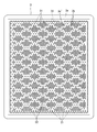
- the perspective view of the cutting state of all the primary combustion type burners The top view of the combustion plate of embodiment of this invention.
- Explanatory drawing which shows the recirculation
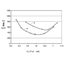
- the graph which shows the combustion test result done using invention and a comparison product.
- the burner 1 indicates an all primary combustion burner.
- the burner 1 includes a burner body 2 formed in a box shape opening upward, and a combustion plate 3 mounted on the upper portion of the burner body 2.
- the width direction of the burner 1 will be described as the horizontal direction
- the depth direction of the burner 1 will be described as the front-back direction.
- the flange part 2a which couple
- a distribution chamber 4 facing the lower surface of the combustion plate 3 and a lower mixing chamber 5 partitioned from the distribution chamber 4 by a floor wall 2b integrated with the burner body 2 are provided.
- An air supply chamber 6 is provided below the mixing chamber 5.
- the combustion fan 7 is connected to an air supply port 62 opened on the bottom surface 61 of the air supply chamber 6 so that primary air is supplied from the combustion fan 7 to the air supply chamber 6.
- a horizontally long opening 41 communicating with the mixing chamber 5 is formed at the rear portion of the floor wall 2b which is the bottom surface of the distribution chamber 4.
- the distribution chamber 4 is divided into two upper and lower spaces by a partition plate 42. The premixed gas flowing into the lower space of the distribution chamber 4 from the mixing chamber 5 through the opening 41 and the combustion plate 3 through the numerous distribution holes 42 a formed in the partition plate 42 and the upper space of the distribution chamber 4. To be guided to.
- the front surface 51 of the mixing chamber 5 is closed by a vertical wall 2c integrated with the burner body 2.
- a plurality of nozzle holes 52 each including a hole penetrating the vertical wall 2c are arranged in parallel on the front surface 51 with a horizontal interval.
- the gas manifold 8 is attached to the outer surface of the vertical wall 2c via a partition plate 81 that defines a nozzle passage 52a communicating with the plurality of nozzle holes 52 between the vertical wall 2c.
- An opening (not shown) for communicating the gas passage 82 in the gas manifold 8 and the nozzle passage 52a is formed in the partition plate 81, and an electromagnetic valve 83 for opening and closing the opening is attached to the gas manifold 8. Yes.
- the electromagnetic valve 83 is opened, the fuel gas is supplied to the nozzle passage 52 a and the fuel gas is injected from each nozzle hole 52.
- a wall plate 55 is erected on the bottom surface 53 of the mixing chamber 5 so as to face the front surface 51 of the mixing chamber 5 with a ventilation gap 54 and to which fuel gas ejected from each nozzle hole 52 collides.
- the wall board 55 is inclined forward and upward.
- a horizontally long air inlet 56 for introducing the primary air from the air supply chamber 6 into the mixing chamber 5 is provided at a portion of the bottom surface 53 of the mixing chamber 5 facing the ventilation gap 54. Then, the fuel gas ejected from each nozzle hole 52 collides with the wall plate 55 and diffuses, and the diffused fuel gas is mixed into the primary air flowing through the ventilation gap 54, thereby promoting the mixing of the fuel gas and the primary air. A homogeneous premixed gas is generated.
- a baffle-like baffle plate 57 that is long in the front-rear direction and is provided below each nozzle hole 52 is provided. According to this, the fuel gas can be reliably collided with the wall plate 55 without being affected by the primary air even during weak combustion in which the amount of fuel gas ejected is small.
- the combustion plate 3 is formed by forming a large number of flame holes 3b in a ceramic plate body 3a, and a premixed gas is ejected from these flame holes 3b and undergoes primary combustion.
- the combustion plate 3 will be described in detail.
- the flame hole 3b is omitted for simplification of the drawing.
- the plate body 3a is provided with flameless holes 31 having no flame holes 3b in a rhombic lattice shape, and each of the regions of the plate body 3a surrounded by the flameless holes 31 has a plurality of flame holes 3b.
- the collecting flame holes 32 are formed densely. Referring to FIG.
- the length L of one side of the rhombus that circumscribes the flame hole 3 b around the collecting flame hole 32 is 9 mm, and the width of the flameless hole 31 between these rhombuses W is 4 mm, and the flame holes 3 b having a diameter of 1.2 mm are formed between the flame holes 3 b in the direction parallel to the longitudinal direction of the flameless hole 31 (direction parallel to each side of the rhombus).
- a total of 25 pieces are formed so that the distance (inter-center distance) P is 1.95 mm.
- flame holes (outer flame holes) 3b ′ are formed on each side portion of the flameless hole portion 31 adjacent to the collective flame hole portion 32 with a predetermined interval in the longitudinal direction of the flameless hole portion 31. ing.
- This predetermined interval that is, the center-to-center distance P ′ in the longitudinal direction of the flameless hole 31 of the outer flame hole 3 b ′ is in the longitudinal direction of the flameless hole 31 of the flame hole 3 b formed in the collective flame hole 32. It is set wider than the center-to-center distance P in the parallel direction.
- the outer flame hole 3 b ′ has the same diameter as the flame hole 3 b formed in the collective flame hole portion 32.
- the outer flame hole 3 b ′ on one side in the width direction of the flameless hole portion 31 and the outer flame hole 3 b ′ on the other side are arranged with their positions shifted in the longitudinal direction of the flameless hole portion 31.
- the flameless hole 31 is formed at the apex of the isosceles triangle T with the line connecting the centers of the two outer flame holes 3b ′ and 3b ′ adjacent to each other in the width direction of the flameless hole 31 as the base.
- the position of the outer flame hole 3b 'on one side in the width direction of the flameless hole portion 31 and the outer flame hole 3b' on the other side of the flameless hole portion 31 is set so that the center of the outer flame hole 3b 'on the opposite side in the width direction is positioned.
- the part 31 is shifted in the longitudinal direction. As a result, the distances between the outer flame holes 3b ′ and 3b ′ on both sides in the width direction of the flameless hole portion 31 are all equal.
- the outer flame holes 3b ′ are arranged at places outside the peripheral portion of the collecting flame hole portion 32.
- the collective flame hole portion 32 located on the opposite side of the flameless hole portion 31 with respect to the premixed gas refluxed from the outer flame hole 3 b ′ onto the flameless hole portion 31.
- the premixed gas flowing back from the peripheral flame hole 3b onto the non-flame hole part 31 does not interfere, but also the peripheral flame hole 3b of the collective flame hole part 32 located on the same side as the outer flame hole 3b ′. To the flameless hole 31 interferes with the premixed gas.
- the flameless hole part when the outer flame hole 3b ′ on one side in the width direction of the flameless hole part 31 and the outer flame hole 3b ′ on the other side are arranged at the same position in the longitudinal direction of the flameless hole part 31, the flameless hole part.
- the width of 31 is considerably narrow at the part between the outer flame holes 3b 'and 3b' on both sides, and the premixed gas does not recirculate well at this part, and the flame holding effect of the outer flame hole 3b 'is reduced. .
- the outer flame hole 3b ′ on one side in the width direction of the flameless hole portion 31 and the outer flame hole 3b ′ on the other side are arranged with their positions shifted in the longitudinal direction of the flameless hole portion 31. Therefore, the flame holes 3b in the periphery of the collective flame hole 32 on the opposite side across the flameless holes 31 are opposed to the outer flame holes 3b ', and the width of the flameless holes 31 is the outer flame. It is possible to prevent the holes 3b 'and 3b' from being narrowed too small.
- the premixed gas returning from the outer flame holes 3b 'and 3b' on both sides of the flameless hole 31 to the flameless hole 31 also interferes with each other, so that the flame holding of the outer flame hole 3b 'is performed.
- the effect is further improved.
- the combustion plate (invention product) of the above embodiment in which the dimensions L, W, P, and P ′ in FIG.
- the combustion test was conducted with the outer flame hole 3b 'having the illustrated dimensions, but with the combustion plate (comparative product) omitted, with the heat exchanger disposed above the burner.
- the CO concentration in the combustion exhaust gas that passed through the heat exchanger was measured with the primary air amount kept constant and the input (supply amount in terms of calorific value of fuel gas) changed.
- the primary air amount was set so that the excess air ratio was 1.3 when the input was 10 kW.
- the excess air ratio of the premixed gas is lowered by increasing the input, it is difficult to completely mix the fuel gas and the primary air. Therefore, the excess air ratio in the injected gas from the combustion plate is partially Therefore, it becomes less than 1 and incomplete combustion occurs, and the CO concentration increases. Further, when the excess air ratio of the premixed gas is increased by reducing the input, flame lift is likely to occur, and the flame contacts the heat exchanger before the completion of the combustion reaction, thereby increasing the CO concentration. As is clear from FIG.
- the shape of the collecting flame hole portion 32 is a rhombus, but this shape may be a square or a triangle other than the rhombus.
- the outer flame hole 3 b ′ may have a hole diameter different from that of the flame hole 3 b of the collective flame hole portion 32.
- SYMBOLS 3 Combustion plate, 3a ... Plate main body, 3b ... Flame hole, 3b '... Outer flame hole, 31 ... Flameless hole part, 32 ...
- Collective flame hole part, P Flameless flame formed in collective flame hole part Distance between centers in the direction parallel to the longitudinal direction of the hole, P ′: Distance between centers in the longitudinal direction of the flameless hole of the outer flame hole, T: Isosceles triangle.
Landscapes
- Engineering & Computer Science (AREA)
- Chemical & Material Sciences (AREA)
- Combustion & Propulsion (AREA)
- Mechanical Engineering (AREA)
- General Engineering & Computer Science (AREA)
- Gas Burners (AREA)
Abstract
Description
Claims (4)
- セラミック製のプレート本体に、予混合ガスを噴出する多数の炎孔を形成した全一次燃焼式バーナ用の燃焼プレートであって、
プレート本体に炎孔が存在しない無炎孔部が格子状に設けられ、無炎孔部で囲われるプレート本体の各領域を複数の炎孔が密集して形成される集合炎孔部とするものにおいて、
無炎孔部の各集合炎孔部に隣接する各側部に、無炎孔部の長手方向に所定の間隔を存して炎孔が形成され、この所定の間隔は、集合炎孔部に形成する炎孔間の無炎孔部の長手方向に平行な方向の間隔よりも広く設定されることを特徴とする燃焼プレート。 - 前記集合炎孔部に形成する炎孔の前記無炎孔部の長手方向に平行な方向の中心間距離をP、無炎孔部の前記各側部に形成する炎孔の無炎孔部の長手方向の中心間距離をP´として、P´≧2Pに設定されることを特徴とする請求項1記載の燃焼プレート。
- 前記無炎孔部の各側部に形成される炎孔を外側炎孔として、無炎孔部の幅方向一側の外側炎孔と他側の外側炎孔とが無炎孔部の長手方向に位置をずらして配置されることを特徴とする請求項1又は2記載の燃焼プレート。
- 前記無炎孔部の幅方向各側の隣り合う2つの外側炎孔の中心を結ぶ線を底辺とする二等辺三角形の頂点に無炎孔部の幅方向反対側の外側炎孔の中心が位置することを特徴とする請求項3記載の燃焼プレート。
Priority Applications (4)
| Application Number | Priority Date | Filing Date | Title |
|---|---|---|---|
| AU2012224388A AU2012224388B2 (en) | 2011-03-02 | 2012-02-29 | Combustion plate |
| EP12751908.0A EP2682676B1 (en) | 2011-03-02 | 2012-02-29 | Combustion plate |
| US13/985,401 US9182118B2 (en) | 2011-03-02 | 2012-02-29 | Combustion plate |
| CA2828691A CA2828691C (en) | 2011-03-02 | 2012-02-29 | Combustion plate |
Applications Claiming Priority (2)
| Application Number | Priority Date | Filing Date | Title |
|---|---|---|---|
| JP2011044826A JP5513425B2 (ja) | 2011-03-02 | 2011-03-02 | 燃焼プレート |
| JP2011-044826 | 2011-03-02 |
Publications (1)
| Publication Number | Publication Date |
|---|---|
| WO2012117726A1 true WO2012117726A1 (ja) | 2012-09-07 |
Family
ID=46757669
Family Applications (1)
| Application Number | Title | Priority Date | Filing Date |
|---|---|---|---|
| PCT/JP2012/001379 Ceased WO2012117726A1 (ja) | 2011-03-02 | 2012-02-29 | 燃焼プレート |
Country Status (6)
| Country | Link |
|---|---|
| US (1) | US9182118B2 (ja) |
| EP (1) | EP2682676B1 (ja) |
| JP (1) | JP5513425B2 (ja) |
| AU (1) | AU2012224388B2 (ja) |
| CA (1) | CA2828691C (ja) |
| WO (1) | WO2012117726A1 (ja) |
Families Citing this family (5)
| Publication number | Priority date | Publication date | Assignee | Title |
|---|---|---|---|---|
| KR101319256B1 (ko) * | 2012-03-05 | 2013-10-17 | 주식회사 경동나비엔 | 연소기기용 가스 공기 혼합장치 |
| WO2015139215A1 (zh) * | 2014-03-18 | 2015-09-24 | 詹政通 | 红外线瓦斯炉具的炉心结构 |
| JP2016084955A (ja) * | 2014-10-24 | 2016-05-19 | リンナイ株式会社 | 燃焼プレート |
| JP6216365B2 (ja) * | 2015-12-28 | 2017-10-18 | 川崎重工業株式会社 | 平面燃焼バーナ用バーナプレート |
| JP6853075B2 (ja) * | 2017-03-13 | 2021-03-31 | リンナイ株式会社 | 全一次燃焼式バーナ |
Citations (5)
| Publication number | Priority date | Publication date | Assignee | Title |
|---|---|---|---|---|
| JPH027428U (ja) * | 1988-06-29 | 1990-01-18 | ||
| JPH06147435A (ja) * | 1992-11-11 | 1994-05-27 | Miura Co Ltd | 表面燃焼バーナ |
| JPH07119935A (ja) * | 1993-10-19 | 1995-05-12 | Miura Co Ltd | 予混合式バーナ |
| JPH11351522A (ja) | 1998-04-08 | 1999-12-24 | Rinnai Corp | 燃焼用バ―ナプレ―ト |
| JP2004324910A (ja) * | 2003-04-21 | 2004-11-18 | Rinnai Corp | 全周型バーナ |
Family Cites Families (9)
| Publication number | Priority date | Publication date | Assignee | Title |
|---|---|---|---|---|
| JPH0712713U (ja) * | 1993-06-09 | 1995-03-03 | エイケン工業株式会社 | ガスバーナ用炎口面板 |
| JP3317371B2 (ja) * | 1993-11-02 | 2002-08-26 | 日立化成工業株式会社 | 低NOxバーナ及び該低NOxバーナを用いた燃焼装置 |
| JP3015931B2 (ja) * | 1995-04-14 | 2000-03-06 | 株式会社成田製陶所 | 燃焼プレート |
| US7717704B2 (en) * | 2007-03-28 | 2010-05-18 | Prince Castle, Inc. | Wire mesh burner plate for a gas oven burner |
| JP5106983B2 (ja) * | 2007-10-25 | 2012-12-26 | 株式会社パロマ | 全一次空気式バーナ |
| JP4818305B2 (ja) * | 2008-04-09 | 2011-11-16 | リンナイ株式会社 | ガスストーブ用プレート式バーナ |
| JP5507966B2 (ja) * | 2009-11-09 | 2014-05-28 | 東邦瓦斯株式会社 | 燃焼プレート |
| DE102010051414B4 (de) * | 2010-11-16 | 2013-10-24 | Ulrich Dreizler | Verbrennungsverfahren mit kühler Flammenwurzel |
| US8827693B2 (en) * | 2011-10-17 | 2014-09-09 | Rinnai Corporation | Totally aerated combustion burner |
-
2011
- 2011-03-02 JP JP2011044826A patent/JP5513425B2/ja active Active
-
2012
- 2012-02-29 CA CA2828691A patent/CA2828691C/en active Active
- 2012-02-29 WO PCT/JP2012/001379 patent/WO2012117726A1/ja not_active Ceased
- 2012-02-29 EP EP12751908.0A patent/EP2682676B1/en active Active
- 2012-02-29 US US13/985,401 patent/US9182118B2/en active Active
- 2012-02-29 AU AU2012224388A patent/AU2012224388B2/en not_active Ceased
Patent Citations (5)
| Publication number | Priority date | Publication date | Assignee | Title |
|---|---|---|---|---|
| JPH027428U (ja) * | 1988-06-29 | 1990-01-18 | ||
| JPH06147435A (ja) * | 1992-11-11 | 1994-05-27 | Miura Co Ltd | 表面燃焼バーナ |
| JPH07119935A (ja) * | 1993-10-19 | 1995-05-12 | Miura Co Ltd | 予混合式バーナ |
| JPH11351522A (ja) | 1998-04-08 | 1999-12-24 | Rinnai Corp | 燃焼用バ―ナプレ―ト |
| JP2004324910A (ja) * | 2003-04-21 | 2004-11-18 | Rinnai Corp | 全周型バーナ |
Non-Patent Citations (1)
| Title |
|---|
| See also references of EP2682676A4 |
Also Published As
| Publication number | Publication date |
|---|---|
| US9182118B2 (en) | 2015-11-10 |
| CA2828691A1 (en) | 2012-09-07 |
| AU2012224388A1 (en) | 2013-08-29 |
| US20130337390A1 (en) | 2013-12-19 |
| JP5513425B2 (ja) | 2014-06-04 |
| JP2012180988A (ja) | 2012-09-20 |
| CA2828691C (en) | 2017-07-04 |
| EP2682676A4 (en) | 2014-08-20 |
| EP2682676A1 (en) | 2014-01-08 |
| EP2682676B1 (en) | 2015-08-19 |
| AU2012224388B2 (en) | 2017-03-30 |
Similar Documents
| Publication | Publication Date | Title |
|---|---|---|
| JP2016084955A (ja) | 燃焼プレート | |
| JP5513425B2 (ja) | 燃焼プレート | |
| JP5380304B2 (ja) | ガスボイラー用バーナー | |
| JP6563714B2 (ja) | 燃焼装置 | |
| KR101301545B1 (ko) | 개방 루프 가스 버너 | |
| JP2011252671A (ja) | 燃焼装置 | |
| JP6207740B2 (ja) | リッチリーン燃焼装置 | |
| JP3429460B2 (ja) | 混合部ユニット | |
| JP6853117B2 (ja) | 燃焼装置 | |
| JP4179761B2 (ja) | バーナ装置及びそれを備えた流体加熱装置 | |
| JP3447962B2 (ja) | 燃焼装置 | |
| JP2011214771A (ja) | ガスバーナユニット及びガス給湯機 | |
| JP2015042923A (ja) | 燃焼装置 | |
| US20260049714A1 (en) | Gas burner unit and heat-cooking apparatus provided with the same | |
| JP2007333223A (ja) | 燃焼装置 | |
| JPH0252910A (ja) | 給湯機 | |
| JP7685210B2 (ja) | アフターバーナ及びグリル | |
| JP5280330B2 (ja) | 燃焼装置 | |
| JP6300634B2 (ja) | 赤外線燃焼装置 | |
| JP2009186125A (ja) | 気化式石油燃焼装置 | |
| JPH04108122U (ja) | ガスバーナ | |
| JP2009192089A (ja) | 気化式石油燃焼装置 | |
| JP2009186071A (ja) | 気化式石油燃焼装置 | |
| JP2016090070A (ja) | 燃焼装置 | |
| JP2007107864A (ja) | バーナ及びバーナユニット |
Legal Events
| Date | Code | Title | Description |
|---|---|---|---|
| 121 | Ep: the epo has been informed by wipo that ep was designated in this application |
Ref document number: 12751908 Country of ref document: EP Kind code of ref document: A1 |
|
| WWE | Wipo information: entry into national phase |
Ref document number: 13985401 Country of ref document: US |
|
| ENP | Entry into the national phase |
Ref document number: 2012224388 Country of ref document: AU Date of ref document: 20120229 Kind code of ref document: A Ref document number: 2828691 Country of ref document: CA |
|
| NENP | Non-entry into the national phase |
Ref country code: DE |
|
| WWE | Wipo information: entry into national phase |
Ref document number: 2012751908 Country of ref document: EP |