WO2012118047A1 - Barre omnibus - Google Patents
Barre omnibus Download PDFInfo
- Publication number
- WO2012118047A1 WO2012118047A1 PCT/JP2012/054852 JP2012054852W WO2012118047A1 WO 2012118047 A1 WO2012118047 A1 WO 2012118047A1 JP 2012054852 W JP2012054852 W JP 2012054852W WO 2012118047 A1 WO2012118047 A1 WO 2012118047A1
- Authority
- WO
- WIPO (PCT)
- Prior art keywords
- bus bar
- conductor
- terminal
- folded
- folded portion
- Prior art date
- Legal status (The legal status is an assumption and is not a legal conclusion. Google has not performed a legal analysis and makes no representation as to the accuracy of the status listed.)
- Ceased
Links
Images


Classifications
-
- H—ELECTRICITY
- H01—ELECTRIC ELEMENTS
- H01R—ELECTRICALLY-CONDUCTIVE CONNECTIONS; STRUCTURAL ASSOCIATIONS OF A PLURALITY OF MUTUALLY-INSULATED ELECTRICAL CONNECTING ELEMENTS; COUPLING DEVICES; CURRENT COLLECTORS
- H01R35/00—Flexible or turnable line connectors, i.e. the rotation angle being limited
- H01R35/02—Flexible line connectors without frictional contact members
-
- H—ELECTRICITY
- H01—ELECTRIC ELEMENTS
- H01M—PROCESSES OR MEANS, e.g. BATTERIES, FOR THE DIRECT CONVERSION OF CHEMICAL ENERGY INTO ELECTRICAL ENERGY
- H01M50/00—Constructional details or processes of manufacture of the non-active parts of electrochemical cells other than fuel cells, e.g. hybrid cells
- H01M50/50—Current conducting connections for cells or batteries
- H01M50/502—Interconnectors for connecting terminals of adjacent batteries; Interconnectors for connecting cells outside a battery casing
- H01M50/505—Interconnectors for connecting terminals of adjacent batteries; Interconnectors for connecting cells outside a battery casing comprising a single busbar
-
- H—ELECTRICITY
- H01—ELECTRIC ELEMENTS
- H01M—PROCESSES OR MEANS, e.g. BATTERIES, FOR THE DIRECT CONVERSION OF CHEMICAL ENERGY INTO ELECTRICAL ENERGY
- H01M10/00—Secondary cells; Manufacture thereof
- H01M10/60—Heating or cooling; Temperature control
- H01M10/65—Means for temperature control structurally associated with the cells
- H01M10/655—Solid structures for heat exchange or heat conduction
- H01M10/6553—Terminals or leads
-
- H—ELECTRICITY
- H01—ELECTRIC ELEMENTS
- H01R—ELECTRICALLY-CONDUCTIVE CONNECTIONS; STRUCTURAL ASSOCIATIONS OF A PLURALITY OF MUTUALLY-INSULATED ELECTRICAL CONNECTING ELEMENTS; COUPLING DEVICES; CURRENT COLLECTORS
- H01R11/00—Individual connecting elements providing two or more spaced connecting locations for conductive members which are, or may be, thereby interconnected, e.g. end pieces for wires or cables supported by the wire or cable and having means for facilitating electrical connection to some other wire, terminal, or conductive member, blocks of binding posts
- H01R11/01—Individual connecting elements providing two or more spaced connecting locations for conductive members which are, or may be, thereby interconnected, e.g. end pieces for wires or cables supported by the wire or cable and having means for facilitating electrical connection to some other wire, terminal, or conductive member, blocks of binding posts characterised by the form or arrangement of the conductive interconnection between the connecting locations
-
- H—ELECTRICITY
- H01—ELECTRIC ELEMENTS
- H01M—PROCESSES OR MEANS, e.g. BATTERIES, FOR THE DIRECT CONVERSION OF CHEMICAL ENERGY INTO ELECTRICAL ENERGY
- H01M50/00—Constructional details or processes of manufacture of the non-active parts of electrochemical cells other than fuel cells, e.g. hybrid cells
- H01M50/50—Current conducting connections for cells or batteries
- H01M50/502—Interconnectors for connecting terminals of adjacent batteries; Interconnectors for connecting cells outside a battery casing
- H01M50/503—Interconnectors for connecting terminals of adjacent batteries; Interconnectors for connecting cells outside a battery casing characterised by the shape of the interconnectors
-
- H—ELECTRICITY
- H01—ELECTRIC ELEMENTS
- H01M—PROCESSES OR MEANS, e.g. BATTERIES, FOR THE DIRECT CONVERSION OF CHEMICAL ENERGY INTO ELECTRICAL ENERGY
- H01M50/00—Constructional details or processes of manufacture of the non-active parts of electrochemical cells other than fuel cells, e.g. hybrid cells
- H01M50/50—Current conducting connections for cells or batteries
- H01M50/502—Interconnectors for connecting terminals of adjacent batteries; Interconnectors for connecting cells outside a battery casing
- H01M50/521—Interconnectors for connecting terminals of adjacent batteries; Interconnectors for connecting cells outside a battery casing characterised by the material
- H01M50/522—Inorganic material
-
- H—ELECTRICITY
- H01—ELECTRIC ELEMENTS
- H01R—ELECTRICALLY-CONDUCTIVE CONNECTIONS; STRUCTURAL ASSOCIATIONS OF A PLURALITY OF MUTUALLY-INSULATED ELECTRICAL CONNECTING ELEMENTS; COUPLING DEVICES; CURRENT COLLECTORS
- H01R43/00—Apparatus or processes specially adapted for manufacturing, assembling, maintaining, or repairing of line connectors or current collectors or for joining electric conductors
- H01R43/16—Apparatus or processes specially adapted for manufacturing, assembling, maintaining, or repairing of line connectors or current collectors or for joining electric conductors for manufacturing contact members, e.g. by punching and by bending
-
- H—ELECTRICITY
- H02—GENERATION; CONVERSION OR DISTRIBUTION OF ELECTRIC POWER
- H02G—INSTALLATION OF ELECTRIC CABLES OR LINES, OR OF COMBINED OPTICAL AND ELECTRIC CABLES OR LINES
- H02G5/00—Installations of bus-bars
- H02G5/005—Laminated bus-bars
-
- Y—GENERAL TAGGING OF NEW TECHNOLOGICAL DEVELOPMENTS; GENERAL TAGGING OF CROSS-SECTIONAL TECHNOLOGIES SPANNING OVER SEVERAL SECTIONS OF THE IPC; TECHNICAL SUBJECTS COVERED BY FORMER USPC CROSS-REFERENCE ART COLLECTIONS [XRACs] AND DIGESTS
- Y02—TECHNOLOGIES OR APPLICATIONS FOR MITIGATION OR ADAPTATION AGAINST CLIMATE CHANGE
- Y02E—REDUCTION OF GREENHOUSE GAS [GHG] EMISSIONS, RELATED TO ENERGY GENERATION, TRANSMISSION OR DISTRIBUTION
- Y02E60/00—Enabling technologies; Technologies with a potential or indirect contribution to GHG emissions mitigation
- Y02E60/10—Energy storage using batteries
Definitions
- the present invention relates to a bus bar excellent in bending performance.
- Patent Document 1 discloses a wire harness including a plurality of round electric wires arranged in parallel and a flat cylindrical corrugated tube covering the periphery of the round electric wires.
- the surface area of the part that forms the contour of the entire wire bundle becomes larger than when the multiple wires are bundled in a state of being stacked vertically and horizontally, and heat dissipation of the entire wire bundle is achieved. Increases nature.
- a bus bar made of a plate-like conductor is often adopted as a power line mounted on a vehicle. Since the bus bar has a flat shape, the conductor portion has a larger surface area and higher heat dissipation than a round electric wire having a round core wire having the same cross-sectional area.
- Patent Document 1 when the power line is constituted by a bundle of wires made up of a plurality of covered wires arranged in parallel, the ends of the core wires in each of the plurality of covered wires are bound together electrically. Terminals to be connected are attached to both ends of the wire bundle.
- the present invention provides a bus bar that is excellent in heat dissipation and laying workability even when a conductor has a large cross-sectional area for power lines, and that can prevent excessive heat generation due to poor electrical connection or the like. Objective.
- the bus bar according to the present invention includes the following components.
- the first component is a portion formed of a conductor that is formed extending in the first direction and in which a folded portion that forms a groove along the second direction that intersects the first direction is formed in part. Is an intermediate part.
- a 2nd component is a terminal part which is a part which consists of a conductor connected on both sides in the 1st direction of an intermediate part, and is connected with another member.
- the intermediate portion has a structure in which a plurality of plate-like conductors are overlapped.
- plate-like conductor is used as a term including, for example, a conductor having a thickness of about 0.1 millimeter and a foil-like conductor that is much thinner than that.
- the bus bar which concerns on this invention WHEREIN:
- intersects the longitudinal direction is formed in the intermediate part of the bus bar. Since the folded portion is easily elastically deformed so that the width of the groove expands and contracts, the intermediate portion of the bus bar is easily bent elastically at the folded portion. That is, even when the bus bar according to the present invention is formed to be relatively short and thick, the bus bar has flexibility to bend elastically in the direction of its thickness at the folded portion.
- the bus bar according to the present invention is particularly easily bent at the folded portion. Therefore, when the force of the direction which bends it with respect to the bus-bar which concerns on this invention is added, only a folding
- a bending trace means the site
- terminal portions at both ends of the bus bar are portions that are connected to the middle portion, poor electrical connection is unlikely to occur at the terminal portions of the bus bar.
- the bus bar according to the present invention has excellent heat dissipation and laying workability even when the conductor has a large cross-sectional area for power lines, and prevents excessive heat generation due to poor electrical connection or the like. it can.
- the intermediate portion when the intermediate portion has a multiple structure in which a plurality of thin plate-like conductors overlap, the intermediate portion itself has a thickness direction, that is, a direction in which the plurality of plate-like conductors are stacked. It has flexibility. Therefore, in the bus bar according to the present invention, when the intermediate portion has a multiple structure, the bending performance of the intermediate portion is further enhanced by the action of the folded portion and the action of the multiple structure.
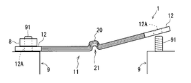
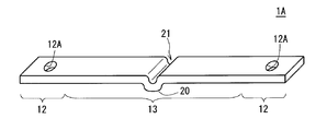
- bus bar 1 concerning a 1st embodiment of the present invention. It is a side view of the bus bar 1 in the middle of being attached to a terminal block. It is a figure which shows the example of the manufacturing method of the bus bar. It is a perspective view of 1 A of bus bars which concern on 2nd Embodiment of this invention.
- the bus bar 1 is used, for example, as a power line that connects an inverter circuit and a motor or a generator in an electric vehicle, or as a power line that connects a battery and an inverter circuit.
- the bus bar 1 is a conductor member made of metal such as copper, for example, and is formed to extend in one direction as shown in FIG.
- the longitudinal direction of the bus bar 1 is referred to as a first direction
- the width direction of the bus bar 1, that is, a direction orthogonal to the first direction is referred to as a second direction. 1 to 4, the first direction is the left-right direction.
- the bus bar 1 includes an intermediate portion 11 and terminal portions 12 at both ends.
- the bus bar 1 is laid as a part of a power transmission path to each phase of an electric motor such as a three-phase motor.
- the intermediate portion 11 of the bus bar 1 is a portion made of a conductor that is formed to extend in the first direction and in which a folded portion 20 that forms a groove 21 along the second direction is formed. Furthermore, the intermediate portion 11 of the bus bar 1 has a structure in which a plurality of plate-like conductors 11A are overlapped.
- the terminal part 12 is a part which consists of a conductor connected to both ends of the intermediate part 11 and is connected to other members.
- the terminal portion 12 is formed with a terminal hole 12 ⁇ / b> A for being connected to a connection end at the front stage and the rear stage of the power transmission path by a fixing tool such as a bolt.
- FIG. 2 is a side view of the bus bar 1 in the middle of being attached to the terminal block 9 at the front and rear stages of the power transmission path.
- the stud bolt 91 provided on the terminal block 9 is passed through the terminal hole 12 ⁇ / b> A of the terminal portion 12 in the bus bar 1, and the nut 8 is attached to the stud bolt 91.
- the terminal portion 12 is fixed to the terminal block 9 and is electrically connected to the terminal block 9.
- the bus bar 1 Since the bus bar 1 has a flat cross section, the ratio of the surface area to the cross sectional area is large, and the heat dissipation is high.
- a folded portion 20 is formed in the middle portion 11 of the bus bar 1 to form a groove 21 along the second direction intersecting the longitudinal direction.
- the folded portion 20 of the bus bar 1 is easily elastically deformed so that the width of the groove 21 is expanded and contracted, the intermediate portion 11 of the bus bar 1 is easily elastically bent at the folded portion 20. . That is, even if the bus bar 1 is formed to be relatively short and thick, the folded portion 20 has flexibility to bend elastically in the thickness direction.
- the bus bar 1 is formed so that the groove 21 of the folded portion 20 is located on the opposite side to the side where the terminal portion 12 is to be bent, that is, the groove 21 of the folded portion 20 is bent. It is desirable to be used so that it is located outside the part.
- the intermediate portion 11 of the bus bar 1 has a structure in which a plurality of thin plate-like conductors 11A are overlapped. Therefore, the intermediate portion 11 of the bus bar 1 has flexibility in the thickness direction, that is, in the direction in which the plurality of plate-like conductors 11A are stacked, regardless of the presence or absence of the folded portion 20. Therefore, the intermediate portion 11 of the bus bar 1 has a very high bending performance and is elastically bent greatly due to the action of the folded portion 20 and the action of the multiple structure.
- the terminal portion 12 in the laying operation of the bus bar 1, the terminal portion 12 can be positioned at a target position while the intermediate portion 11 is elastically bent.
- the bus bar 1 is excellent in laying workability compared to a conventional bus bar that cannot be bent easily.
- the bus bar 1 is particularly easy to bend at the folded portion 20. Therefore, when the force of the direction which bends it with respect to the bus-bar 1 is added, only the folding
- terminal portions 12 at both ends of the bus bar 1 are portions connected to a plurality of plate-like conductors 11A that overlap in the intermediate portion 11, for example, a portion where a plurality of overlapped plate-like conductors are integrally welded, or an intermediate portion
- the part 11 is configured as a part originally connected to each of the plurality of conductors of the part 11. Therefore, poor electrical connection is unlikely to occur in the terminal portion 12 of the bus bar 1.
- the bus bar 1 is excellent in heat dissipation and laying workability even when the cross-sectional area is large for power lines, and prevents excessive heat generation due to poor electrical connection or the like. It has the characteristics that can be done.
- the manufacturing method according to this example includes an overlapping process shown in FIG. 3A, a press-forming process shown in FIG. 3B, and a joining process not shown.
- the superposition process is a process of superposing a plurality of thin members 110 made of a plate-like conductor thinner than the thickness of the bus bar 1.
- the thin member 110 is a conductor member made of a metal such as copper, for example, and includes an intermediate portion 111 and terminal portions 112 at both ends.
- the terminal portion 112 is formed with a through hole 112A.
- the plurality of thin members 110 are formed with lengths that are slightly different in length in the first direction so that the positions of both ends are aligned after the folded portion 20 is formed.
- the press molding process is a process of forming the folded portion 20 by pressing a part of the intermediate portion 111 of the plurality of thin-walled members 110 that are overlapped.
- the intermediate portion 111 of the plurality of thin-walled members 110 overlaid is a first mold 41 in which a groove 411 that forms the outer surface of the folded portion 20 is formed, and the folded portion 20. Is sandwiched between the second mold 42 formed with the projection 421 for forming the groove 21. Thereby, the folding
- the unillustrated joining step is a step of forming the terminal portion 12 by joining both ends of each of the superposed thin members 110 by welding or the like.
- the plurality of thin-walled members 110 that are integrally connected by joining the terminal portions 112 at both ends become the bus bar 1.
- a plurality of thin members 110 made of plate-like conductors thinner than the thickness thereof are overlapped, and the terminal portions 112 at both ends of each of the thin members 110 are joined.
- the junction part in which the some terminal part 112 was joined in both ends, and the intermediate part 111 between the junction parts comprise the terminal part 12 and the intermediate part 11 in the bus bar 1, respectively.
- the bus bar 1 manufactured by the manufacturing method according to the present example can be manufactured by a simple process in which a plurality of thin members 110 having a very simple structure are prepared and they are overlapped and subjected to joining processing such as press processing and welding. This is preferable in terms of points.
- the terminal portion 12 formed by joining a plurality of stacked thin-walled members 110 by welding or the like has poor electrical connection compared to a crimp terminal attached to a bundle of a plurality of core wires. Hateful.
- bus bar 1A according to a second embodiment of the present invention will be described with reference to FIG.
- This bus bar 1A is different from the bus bar 1 shown in FIG. 1 only in that the intermediate portion does not have a multiple structure. 4, the same components as those shown in FIG. 1 are given the same reference numerals. Hereinafter, only the differences between the bus bar 1A and the bus bar 1 will be described.
- the bus bar 1A is formed extending in the first direction, and an intermediate portion 13 made of a conductor formed with a folded portion 20 that forms a groove 21 along the second direction in a part thereof, and an intermediate portion 11 is a member made of a conductor formed of a conductor connected to both ends of the terminal 11 and a terminal portion 12 that is a portion connected to another member.
- the intermediate portion 13 of the bus bar 1A does not have a multiple structure like the intermediate portion 11 of the bus bar 1. That is, the bus bar 1A has a structure in which the folded portion 20 is formed in a part of an intermediate region excluding a part of both ends of one plate-like conductor having the same thickness as the bus bar 1A.
- bus bar 1A is formed in a flat shape like the bus bar 1, the ratio of the surface area to the cross-sectional area is large and the heat dissipation is high.
- a folded portion 20 that forms a groove 21 along the second direction intersecting the longitudinal direction is formed in the intermediate portion 13 of the bus bar 1A. Therefore, even when the bus bar 1A is formed to be relatively short and thick, the folded portion 20 has flexibility to bend elastically in the thickness direction.
- the bus bar 1A is particularly easily bent at the folded-back portion 20. Therefore, when the force of the direction which bends it with respect to 1 A of bus bars is added, only the folding
- terminal portions 12 at both ends of the bus bar 1A are originally integral parts, unlike the case where the terminals are attached to a plurality of core wires, there is no electrical connection failure.
- the bus bar 1A is excellent in heat dissipation and laying workability even when the cross-sectional area is large for a power line, and generates excessive heat due to poor electrical connection. It has characteristics that can be prevented.
- the bus bars 1, 1 ⁇ / b> A have the folded portion 20 at one place of the intermediate portions 11, 13.
- a plurality of folded portions 20 may be formed in the intermediate portions 11 and 13 of the bus bars 1 and 1A.
- the folded portion 20 in the intermediate portion 11 of the bus bar 1 may be formed by other methods besides the case of being formed by bending the plurality of stacked thin members 110.
- folded portions having slightly different groove depths and widths are formed in the intermediate portion 111 of each of the plurality of thin members 110.
- the plurality of thin members 110 formed with the folded portions are overlapped, and then the terminal portions 112 at both ends of the overlapped thin members 110 are joined by welding or the like.
- the bus bars 1 and 1A are used in a state where the intermediate portions 11 and 13 are covered with an insulating member.
- the insulating member may be composed of an insulating elastic member made of, for example, rubber or an elastomer (elastic polymer) that is a rubber-based material. Elastomers include vulcanized rubbers such as natural rubber and synthetic rubber, urethane rubber, silicone rubber and fluoro rubber. In general, a thermosetting resin-based elastomer is used as a material for an insulating member made of elastomer. If the insulating member is a member made of an elastomer having excellent flexibility, the flexibility of the intermediate portions 11 and 13 of the bus bars 1 and 1A is not hindered.
- the insulating member covering the intermediate portions 11 and 13 of the bus bars 1 and 1A is made of a resin such as polyamide (PA), polypropylene (PP), polybutylene terephthalate (PBT), ABS resin, or polyethylene (PE). Is also possible. It is also conceivable that the insulating member covering the intermediate portions 11 and 13 is a heat shrinkable tube.
- PA polyamide
- PP polypropylene
- PBT polybutylene terephthalate
- ABS resin polyethylene
- PE polyethylene
- the bus bars 1 and 1A may be used in a state where the intermediate portions 11 and 13 are covered with an insulating member, and the periphery of the insulating member is covered with a shield member such as a braided wire.
- the bus bars 1 and 1A are covered with a shielding member such as a braided wire around the insulating member covering the intermediate portions 11 and 13, and the outside thereof is insulative such as a resin protective tube or tape having flexibility. It may be used in a state covered with the exterior member.
- bus bars 1, 1 ⁇ / b> A may be used in a state in which their intermediate portions 11, 13 are covered and connected by an insulating member, arranged in parallel at intervals along one plane. Conceivable.
Landscapes
- Chemical & Material Sciences (AREA)
- Chemical Kinetics & Catalysis (AREA)
- Electrochemistry (AREA)
- General Chemical & Material Sciences (AREA)
- Engineering & Computer Science (AREA)
- Manufacturing & Machinery (AREA)
- Non-Insulated Conductors (AREA)
Abstract
L'invention a pour objectif de fournir une barre omnibus présentant d'excellentes propriétés de dissipation de la chaleur et d'usinabilité de sa construction, et empêchant une génération de chaleur excessive due à une mauvaise connexion électrique, y compris dans le cas d'une large section transversale de conducteur servant de fil électrique. La barre omnibus (1) consiste en un élément dans lequel sont formées : une partie intermédiaire (11) qui est formée en extension sur une première partie, et qui consiste en une section constituée d'un conducteur dans lequel est formée une section de repli (20) formant une rainure (21) suivant une seconde direction croisant une première direction sur une partie; et des parties borne (12) consistant en des sections raccordées à un autre élément constitué d'un conducteur reliant les deux extrémités de la partie intermédiaire (11) dans la première direction. De préférence, la partie intermédiaire (11) possède une structure dans laquelle une pluralité de conducteurs de forme plate (11A) est superposée.
Applications Claiming Priority (2)
| Application Number | Priority Date | Filing Date | Title |
|---|---|---|---|
| JP2011044715A JP2012182043A (ja) | 2011-03-02 | 2011-03-02 | バスバー |
| JP2011-044715 | 2011-03-02 |
Publications (1)
| Publication Number | Publication Date |
|---|---|
| WO2012118047A1 true WO2012118047A1 (fr) | 2012-09-07 |
Family
ID=46757979
Family Applications (1)
| Application Number | Title | Priority Date | Filing Date |
|---|---|---|---|
| PCT/JP2012/054852 Ceased WO2012118047A1 (fr) | 2011-03-02 | 2012-02-28 | Barre omnibus |
Country Status (2)
| Country | Link |
|---|---|
| JP (1) | JP2012182043A (fr) |
| WO (1) | WO2012118047A1 (fr) |
Cited By (7)
| Publication number | Priority date | Publication date | Assignee | Title |
|---|---|---|---|---|
| WO2014104367A1 (fr) * | 2012-12-28 | 2014-07-03 | 株式会社神戸製鋼所 | Barre omnibus, module de bar omnibus et procédé de fabrication de barre omnibus |
| WO2015118974A1 (fr) * | 2014-02-10 | 2015-08-13 | 株式会社オートネットワーク技術研究所 | Élément de distribution de puissance |
| CN110770945A (zh) * | 2017-07-18 | 2020-02-07 | 松下知识产权经营株式会社 | 汇流条以及电池层叠体 |
| EP3799213A1 (fr) * | 2019-09-24 | 2021-03-31 | TE Connectivity Germany GmbH | Agencement de connexion électrique comprenant une barre omnibus dotée d'un agencement de conducteur, qui est connecté à l'aide de ladite barre et élément de pince |
| US11139646B2 (en) * | 2019-06-10 | 2021-10-05 | Yazaki Corporation | Conduction system for vehicle |
| CN114245953A (zh) * | 2019-08-27 | 2022-03-25 | 株式会社自动网络技术研究所 | 可挠性汇流条、复合汇流条、蓄电组以及可挠性汇流条的制造方法 |
| US20250183604A1 (en) * | 2023-11-30 | 2025-06-05 | Stafl Systems, LLC | Multi-layered flexible bus bar |
Families Citing this family (9)
| Publication number | Priority date | Publication date | Assignee | Title |
|---|---|---|---|---|
| US10396405B2 (en) * | 2014-11-10 | 2019-08-27 | Te Connectivity Corporation | Bus bar for a battery connector system |
| KR102397857B1 (ko) | 2015-07-15 | 2022-05-12 | 삼성에스디아이 주식회사 | 이차 전지 및 이를 이용한 전지 모듈 |
| JP7056507B2 (ja) * | 2018-10-16 | 2022-04-19 | トヨタ自動車株式会社 | バスバー |
| EP3926751B1 (fr) * | 2019-12-03 | 2023-06-14 | Contemporary Amperex Technology Co., Limited | Batterie secondaire avec élément collecteur de courant spécifique, module de batterie et dispositif |
| KR102944241B1 (ko) | 2019-12-31 | 2026-03-25 | 삼성에스디아이 주식회사 | 배터리 팩 |
| KR102926964B1 (ko) | 2020-05-15 | 2026-02-11 | 주식회사 엘지에너지솔루션 | 화재 안전성이 우수한 버스바 |
| JP2022024667A (ja) * | 2020-07-28 | 2022-02-09 | 住友電装株式会社 | 端子台 |
| JP2025020733A (ja) * | 2023-07-31 | 2025-02-13 | 株式会社オートネットワーク技術研究所 | バスバー及び配線モジュール |
| DE102024208341B3 (de) | 2024-09-03 | 2026-02-26 | Volkswagen Aktiengesellschaft | Umformvorrichtung mit einem Werkzeug zum Umformen eines Vorformlings zu einem Stromschienen-Rohling |
Citations (7)
| Publication number | Priority date | Publication date | Assignee | Title |
|---|---|---|---|---|
| JPS57117013U (fr) * | 1981-01-13 | 1982-07-20 | ||
| JPS57195787U (fr) * | 1981-06-06 | 1982-12-11 | ||
| JPS57203478U (fr) * | 1981-06-22 | 1982-12-24 | ||
| JPS6033766U (ja) * | 1982-09-01 | 1985-03-07 | 三菱電線工業株式会社 | 電力用可撓性接続部材 |
| JPS6176680U (fr) * | 1984-10-25 | 1986-05-23 | ||
| JPS6380770U (fr) * | 1986-11-15 | 1988-05-27 | ||
| JPH0545908U (ja) * | 1991-10-16 | 1993-06-18 | 日立伸材株式会社 | 給電用接続導体 |
-
2011
- 2011-03-02 JP JP2011044715A patent/JP2012182043A/ja active Pending
-
2012
- 2012-02-28 WO PCT/JP2012/054852 patent/WO2012118047A1/fr not_active Ceased
Patent Citations (7)
| Publication number | Priority date | Publication date | Assignee | Title |
|---|---|---|---|---|
| JPS57117013U (fr) * | 1981-01-13 | 1982-07-20 | ||
| JPS57195787U (fr) * | 1981-06-06 | 1982-12-11 | ||
| JPS57203478U (fr) * | 1981-06-22 | 1982-12-24 | ||
| JPS6033766U (ja) * | 1982-09-01 | 1985-03-07 | 三菱電線工業株式会社 | 電力用可撓性接続部材 |
| JPS6176680U (fr) * | 1984-10-25 | 1986-05-23 | ||
| JPS6380770U (fr) * | 1986-11-15 | 1988-05-27 | ||
| JPH0545908U (ja) * | 1991-10-16 | 1993-06-18 | 日立伸材株式会社 | 給電用接続導体 |
Cited By (12)
| Publication number | Priority date | Publication date | Assignee | Title |
|---|---|---|---|---|
| WO2014104367A1 (fr) * | 2012-12-28 | 2014-07-03 | 株式会社神戸製鋼所 | Barre omnibus, module de bar omnibus et procédé de fabrication de barre omnibus |
| CN104885319A (zh) * | 2012-12-28 | 2015-09-02 | 株式会社神户制钢所 | 母线、母线模块以及母线的制造方法 |
| US9620263B2 (en) | 2012-12-28 | 2017-04-11 | Kobe Steel, Ltd. | Bus bar, bus bar module, and method of manufacturing bus bar |
| CN104885319B (zh) * | 2012-12-28 | 2017-05-24 | 株式会社神户制钢所 | 母线、母线模块以及母线的制造方法 |
| WO2015118974A1 (fr) * | 2014-02-10 | 2015-08-13 | 株式会社オートネットワーク技術研究所 | Élément de distribution de puissance |
| CN110770945A (zh) * | 2017-07-18 | 2020-02-07 | 松下知识产权经营株式会社 | 汇流条以及电池层叠体 |
| US11139646B2 (en) * | 2019-06-10 | 2021-10-05 | Yazaki Corporation | Conduction system for vehicle |
| CN114245953A (zh) * | 2019-08-27 | 2022-03-25 | 株式会社自动网络技术研究所 | 可挠性汇流条、复合汇流条、蓄电组以及可挠性汇流条的制造方法 |
| EP3799213A1 (fr) * | 2019-09-24 | 2021-03-31 | TE Connectivity Germany GmbH | Agencement de connexion électrique comprenant une barre omnibus dotée d'un agencement de conducteur, qui est connecté à l'aide de ladite barre et élément de pince |
| CN112636032A (zh) * | 2019-09-24 | 2021-04-09 | 泰连德国有限公司 | 包括具有导体布置的母线的电气连接布置以及夹子元件 |
| US20250183604A1 (en) * | 2023-11-30 | 2025-06-05 | Stafl Systems, LLC | Multi-layered flexible bus bar |
| US12489260B2 (en) * | 2023-11-30 | 2025-12-02 | Stafl Systems, LLC | Multi-layered flexible bus bar |
Also Published As
| Publication number | Publication date |
|---|---|
| JP2012182043A (ja) | 2012-09-20 |
Similar Documents
| Publication | Publication Date | Title |
|---|---|---|
| WO2012118047A1 (fr) | Barre omnibus | |
| WO2012118046A1 (fr) | Ensemble de barres omnibus, et procédé de fabrication de celui-ci | |
| US10522266B2 (en) | Wire harness, method for transporting wire harness with device, and method for connecting devices with wire harness | |
| JP6278272B2 (ja) | 導電線及びその配索構造 | |
| CN107710900B (zh) | 屏蔽结构以及屏蔽用编织部件 | |
| US10236634B2 (en) | Electromagnetic shield member and electromagnetic shield member-equipped wiring device | |
| JP6673404B2 (ja) | 導電部材 | |
| US9793625B2 (en) | Electric wire with connecting terminal and method for manufacturing such electric wire | |
| JP2012182051A (ja) | バスバー | |
| CN103946069A (zh) | 线束 | |
| US9643545B2 (en) | Wire harness | |
| CN103108780A (zh) | 用于导电路径的屏蔽部件和线束 | |
| KR20200116880A (ko) | 플렉서블 버스바 | |
| CN105655824A (zh) | 线束 | |
| JP2015201284A (ja) | ワイヤハーネス | |
| WO2014021348A1 (fr) | Élément de gaine destiné à un faisceau électrique et faisceau électrique | |
| CN110445280B (zh) | 定子端部连接组件及扁线电机 | |
| JP2016032388A (ja) | ワイヤハーネス | |
| JP6724771B2 (ja) | ワイヤハーネス | |
| WO2015118974A1 (fr) | Élément de distribution de puissance | |
| WO2020004128A1 (fr) | Faisceau de fils | |
| JP6409672B2 (ja) | 電線モジュール | |
| JP2016177956A (ja) | 接続端子付き電線及びその電線の製造方法 | |
| CN107045905A (zh) | 线束制造方法 | |
| JP2021108244A (ja) | 電線 |
Legal Events
| Date | Code | Title | Description |
|---|---|---|---|
| 121 | Ep: the epo has been informed by wipo that ep was designated in this application |
Ref document number: 12752969 Country of ref document: EP Kind code of ref document: A1 |
|
| NENP | Non-entry into the national phase |
Ref country code: DE |
|
| 122 | Ep: pct application non-entry in european phase |
Ref document number: 12752969 Country of ref document: EP Kind code of ref document: A1 |