WO2012120577A1 - Stator de moteur et moteur - Google Patents
Stator de moteur et moteur Download PDFInfo
- Publication number
- WO2012120577A1 WO2012120577A1 PCT/JP2011/006829 JP2011006829W WO2012120577A1 WO 2012120577 A1 WO2012120577 A1 WO 2012120577A1 JP 2011006829 W JP2011006829 W JP 2011006829W WO 2012120577 A1 WO2012120577 A1 WO 2012120577A1
- Authority
- WO
- WIPO (PCT)
- Prior art keywords
- motor
- yoke
- stator
- width
- narrow portion
- Prior art date
- Legal status (The legal status is an assumption and is not a legal conclusion. Google has not performed a legal analysis and makes no representation as to the accuracy of the status listed.)
- Ceased
Links
Images


Classifications
-
- H—ELECTRICITY
- H02—GENERATION; CONVERSION OR DISTRIBUTION OF ELECTRIC POWER
- H02K—DYNAMO-ELECTRIC MACHINES
- H02K1/00—Details of the magnetic circuit
- H02K1/06—Details of the magnetic circuit characterised by the shape, form or construction
- H02K1/12—Stationary parts of the magnetic circuit
- H02K1/14—Stator cores with salient poles
- H02K1/146—Stator cores with salient poles consisting of a generally annular yoke with salient poles
-
- H—ELECTRICITY
- H02—GENERATION; CONVERSION OR DISTRIBUTION OF ELECTRIC POWER
- H02K—DYNAMO-ELECTRIC MACHINES
- H02K1/00—Details of the magnetic circuit
- H02K1/06—Details of the magnetic circuit characterised by the shape, form or construction
- H02K1/12—Stationary parts of the magnetic circuit
- H02K1/16—Stator cores with slots for windings
- H02K1/165—Shape, form or location of the slots
-
- H—ELECTRICITY
- H02—GENERATION; CONVERSION OR DISTRIBUTION OF ELECTRIC POWER
- H02K—DYNAMO-ELECTRIC MACHINES
- H02K21/00—Synchronous motors having permanent magnets; Synchronous generators having permanent magnets
- H02K21/12—Synchronous motors having permanent magnets; Synchronous generators having permanent magnets with stationary armatures and rotating magnets
- H02K21/14—Synchronous motors having permanent magnets; Synchronous generators having permanent magnets with stationary armatures and rotating magnets with magnets rotating within the armatures
- H02K21/16—Synchronous motors having permanent magnets; Synchronous generators having permanent magnets with stationary armatures and rotating magnets with magnets rotating within the armatures having annular armature cores with salient poles
-
- H—ELECTRICITY
- H02—GENERATION; CONVERSION OR DISTRIBUTION OF ELECTRIC POWER
- H02K—DYNAMO-ELECTRIC MACHINES
- H02K2213/00—Specific aspects, not otherwise provided for and not covered by codes H02K2201/00 - H02K2211/00
- H02K2213/03—Machines characterised by numerical values, ranges, mathematical expressions or similar information
Definitions
- a stress changing portion in which a stress is made different from other portions is provided in a part of the yoke of the stator.
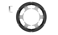
- the structure is known (see, for example, Patent Document 1). Specifically, for example, by providing notches and caulking portions on the outer peripheral surface and part of the inner peripheral surface of the yoke, and fixing the stator by shrink fitting in the case, the notches and caulking portions The compressive stress is increased.
- a stator of a motor includes a cylindrical yoke, an extension portion extending from the yoke inward in a radial direction of the yoke (hereinafter simply referred to as a radial direction), and the extension portion. And a tooth having a wide portion formed so as to spread in the circumferential direction of the yoke (hereinafter simply referred to as the circumferential direction) at the tip, and a portion of the extension portion from other portions of the extension portion A narrow narrow part is provided.
- the magnetic flux density passing through the tooth is increased in the narrow portion, and local magnetic saturation occurs.
- the harmonic flux is filtered.
- the narrow portion is provided in the teeth having a relatively high magnetic flux density in the stator, only the harmonic magnetic flux can be effectively filtered and removed. Therefore, it is possible to reduce the iron loss generated in the motor and obtain a highly efficient motor.
- the extending portion may include a constant width portion extending linearly in a radial direction so that a circumferential width is constant, and the narrow portion having a circumferential width shorter than the constant width portion. .
- the harmonic magnetic flux can be effectively suppressed in the narrow portion whose width in the circumferential direction is shorter than that of the constant width portion while allowing the alternating magnetic flux to easily flow.
- the narrow portion may be provided at a proximal end portion of the extending portion, and the constant width portion may extend radially inward from a distal end of the narrow portion.
- the narrow portion may have an arc shape on both sides in the circumferential direction in a cross-sectional view perpendicular to the central axis of the yoke.
- the ratio of the minimum value d1 of the circumferential width of the narrow portion to the circumferential width d2 of the constant width portion may be 0.70 ⁇ d1 / d2 ⁇ 0.98. By setting it as such a ratio, a harmonic magnetic flux can be suppressed more effectively.
- a motor according to an aspect of the present invention includes the motor stator having the above-described configuration. Thereby, in a motor of the same size, iron loss can be reduced without lowering the torque constant, and a highly efficient motor can be obtained.
- the present invention is configured as described above, and has an effect that a high-efficiency motor can be obtained by reducing iron loss generated in the motor.
- FIG. 1 is a sectional view showing an example of a sectional structure of a motor provided with a rotor of a motor according to an embodiment of the present invention.
- FIG. 2 is a partially enlarged view showing a cross-sectional structure of the stator of the motor shown in FIG.
- FIG. 3 is an explanatory diagram showing a local magnetic flux flow in the vicinity of the teeth in the stator of the motor shown in FIG.
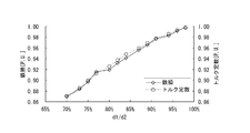
- FIG. 4 shows analysis values of iron loss and torque constant when the minimum value d2 of the circumferential width of the narrow portion of the teeth in the stator shown in FIG. 1 is changed with respect to the circumferential width d1 of the constant width portion. It is a graph to show.
- FIG. 1 is a sectional view showing an example of a sectional structure of a motor provided with a rotor of a motor according to an embodiment of the present invention.
- FIG. 2 is a partially enlarged view showing a cross-sectional structure of the stator of the motor shown in FIG.
- FIG. 5 is a graph showing an analysis value of the motor efficiency when the minimum value d2 of the circumferential width of the narrow portion of the teeth in the stator shown in FIG. 1 is changed with respect to the circumferential width d1 of the constant width portion. is there.
- FIG. 6A is a partially enlarged view showing an example of a cross-sectional structure of a stator in a modification of the first embodiment of the present invention.
- FIG. 6B is a partially enlarged view showing an example of a cross-sectional structure of the stator in the modification of the first embodiment of the present invention.
- FIG. 6C is a partially enlarged view showing an example of a cross-sectional structure of the stator in the modification of the first embodiment of the present invention.
- FIG. 6A is a partially enlarged view showing an example of a cross-sectional structure of a stator in a modification of the first embodiment of the present invention.
- FIG. 6B is a partially enlarged view showing an example of a cross-sectional structure
- FIG. 6D is a partially enlarged view showing an example of a cross-sectional structure of the stator in the modification of the first embodiment of the present invention.
- FIG. 6E is a partially enlarged view showing an example of a cross-sectional structure of the stator in the modification of the first embodiment of the present invention.
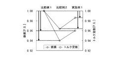
- FIG. 7 is a graph showing the analysis values of the iron loss and torque constant of the stator in Example 1 of the present invention in comparison with the comparative example.
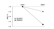
- FIG. 8 is a graph showing the analysis value of the iron loss of the stator in Example 1 of the present invention for each frequency.
- FIG. 9 is a diagram showing the result of analyzing the stress distribution in a conventional stator.
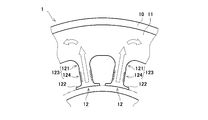
- the stator 1 includes a stator core 13 having a yoke 11 formed in a cylindrical shape and a plurality (18 in the present embodiment) of teeth 12 extending radially inward from the inner wall surface of the yoke 11; A coil 14 wound around each of the teeth 12 is provided. An insulating member 15 (see FIG. 2 described later) is provided between the tooth 12 and the coil 14 to electrically insulate them.
- the rotor 2 is embedded in a cylindrical rotor iron core 21 and a plurality of holes (six in this embodiment) formed in the circumferential direction of the rotor 2 inside the rotor iron core 21. And a plate-like permanent magnet 22.
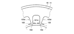
- FIG. 2 is a partially enlarged view showing a cross-sectional structure of the stator of the motor shown in FIG.
- the coil 14 and the insulating member 15 are partially omitted from illustration.
- a narrow portion 121 thinner than other portions is provided in a part of the tooth 12. More specifically, the teeth 12 extend from the yoke 11 to the inside of the yoke 11 in the radial direction (hereinafter simply referred to as the radial direction) and to the tip of the extension portion 123.
- the wide portion 122 since the wide portion 122 is provided, the leakage magnetic flux when the magnetic flux from the rotor 2 flows to the stator 1 in the wide portion 122 is reduced, and further, the harmonic in the narrower narrow portion 121 is reduced. Wave flux is filtered. Therefore, the harmonic magnetic flux can be effectively suppressed without reducing the torque constant of the motor. Further, by forming a portion of the extended portion 123 other than the narrow portion 121 by the constant width portion 124, the constant width portion 124 relaxes magnetic saturation due to the alternating magnetic flux and is more circumferential than the constant width portion 124. Harmonic magnetic flux can be effectively suppressed in the narrow portion 121 having a short width.
- the narrow portion 121 in this embodiment will be described in more detail.
- the narrow portion 121 is provided at the base end portion (a portion close to the yoke 11) of the extension portion 123, and the constant width portion 124 extends radially inward from the distal end of the narrow portion 121. I'm out. Thereby, since the harmonic magnetic flux which crosses via the yoke 11 between adjacent teeth 12 is filtered, a harmonic magnetic flux can be suppressed effectively.
- the narrow portion 121 has an arc shape on both sides in the circumferential direction in a cross-sectional view perpendicular to the central axis of the yoke 11. That is, the width in the circumferential direction of the teeth 11 becomes shorter from the proximal end portion (the portion close to the yoke 11) of the narrow portion 121 toward the distal end, and after the shortest circumferential width d1 is reached, The width in the circumferential direction of the teeth 11 is formed so as to approach d2 as it goes.
- the flow of magnetic flux in the narrow portion 121 becomes gentle, and the amount of change in the magnetic vector at the connection portion between the narrow portion 121 and another portion (the constant width portion 124 or the yoke 11) is reduced.
- the increase in iron loss can be suppressed.
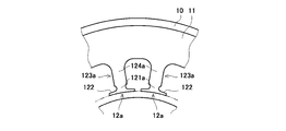
- the narrow portion 121b is provided in the middle portion of the extension portion 123b of the tooth 12b.
- the extending portion 123b has constant width portions 124b extending in the radial direction of the yoke 11 on both radial sides of the narrow portion 121b.
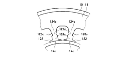
- the extending portion 123d of the tooth 12d has such a shape that the width in the circumferential direction becomes narrower as it goes inward in the radial direction of the yoke 11.
- the leading end portion of 123d is configured as a narrow portion 121d having a narrower circumferential width than other portions of the extending portion 123d.
- stator Example 1 which provided the narrow part 121 as demonstrated in the said embodiment in the teeth 12 of the stator 1 and the stator (Comparative Examples 1 and 2) which do not provide a narrow part in teeth.
- required the iron loss and the torque constant about each of these by analysis is shown.
- the circumferential width of the constant width portion is related to FIG.
- a stator (Comparative Example 1) having the same width d1 as shown in FIG. 5 and a stator (Comparative Example 2) having a width of 0.93d1 were used.
- Example 1 As shown in FIG. 7, the iron loss was reduced by 4% while suppressing the decrease in torque constant to about 1% compared to Comparative Example 1. Therefore, it has been shown that by providing the teeth 12 with the narrow portion 121, it is possible to realize a highly efficient motor capable of reducing iron loss while preventing a reduction in motor output.
- the narrow portions 121 are formed on both sides in the circumferential direction of the yoke 11 in the tooth 12, but the present invention is not limited to this. May be formed. Further, in addition to or instead of the narrow portion formed in the circumferential direction, narrow portions may be formed on both sides of the tooth 12 in the central axis direction of the yoke 11.
- the narrow part 121 is formed in all the teeth 12 which comprise the stator 1, this invention is not restricted to this, Several teeth 12 of the some teeth 12 are provided. A narrow portion may be formed.
- the number of teeth 12, the other shape of teeth 12, the shape of yoke 11, etc. can be suitably set suitably.
- stator of the motor of the present invention and the motor including the same are useful for obtaining a highly efficient motor by reducing iron loss generated in the motor.
Landscapes
- Engineering & Computer Science (AREA)
- Power Engineering (AREA)
- Iron Core Of Rotating Electric Machines (AREA)
Abstract
Priority Applications (3)
| Application Number | Priority Date | Filing Date | Title |
|---|---|---|---|
| US14/003,122 US9548633B2 (en) | 2011-03-08 | 2011-12-06 | Stator of motor having tooth portions with different widths |
| CN201180069041.0A CN103415979B (zh) | 2011-03-08 | 2011-12-06 | 电动机的定子以及电动机 |
| JP2013503235A JP5895168B2 (ja) | 2011-03-08 | 2011-12-06 | モータの固定子およびモータ |
Applications Claiming Priority (2)
| Application Number | Priority Date | Filing Date | Title |
|---|---|---|---|
| JP2011-050283 | 2011-03-08 | ||
| JP2011050283 | 2011-03-08 |
Publications (1)
| Publication Number | Publication Date |
|---|---|
| WO2012120577A1 true WO2012120577A1 (fr) | 2012-09-13 |
Family
ID=46797589
Family Applications (1)
| Application Number | Title | Priority Date | Filing Date |
|---|---|---|---|
| PCT/JP2011/006829 Ceased WO2012120577A1 (fr) | 2011-03-08 | 2011-12-06 | Stator de moteur et moteur |
Country Status (4)
| Country | Link |
|---|---|
| US (1) | US9548633B2 (fr) |
| JP (1) | JP5895168B2 (fr) |
| CN (1) | CN103415979B (fr) |
| WO (1) | WO2012120577A1 (fr) |
Cited By (2)
| Publication number | Priority date | Publication date | Assignee | Title |
|---|---|---|---|---|
| CN104184226A (zh) * | 2013-05-24 | 2014-12-03 | 松下电器产业株式会社 | 电动机以及具备该电动机的压缩机 |
| JP2020005370A (ja) * | 2018-06-26 | 2020-01-09 | ダイハツ工業株式会社 | 回転機 |
Families Citing this family (6)
| Publication number | Priority date | Publication date | Assignee | Title |
|---|---|---|---|---|
| WO2013021559A1 (fr) * | 2011-08-05 | 2013-02-14 | パナソニック株式会社 | Stator de moteur et moteur |
| FR3028110B1 (fr) * | 2014-11-03 | 2018-04-13 | Valeo Equipements Electriques Moteur | Stator pour un alternateur ou une machine electrique |
| DE102016211833A1 (de) * | 2016-06-30 | 2018-01-04 | Robert Bosch Gmbh | Wicklungsträger |
| WO2018108279A1 (fr) * | 2016-12-15 | 2018-06-21 | L-3 Communications Magnet-Motor Gmbh | Stator d'une machine électrique et machine électrique pourvue d'un tel stator |
| CN110266126B (zh) * | 2019-07-19 | 2021-10-01 | 珠海格力节能环保制冷技术研究中心有限公司 | 定子铁芯、定子、电机和空调器 |
| JP7666109B2 (ja) * | 2021-05-12 | 2025-04-22 | スズキ株式会社 | 回転電機 |
Citations (2)
| Publication number | Priority date | Publication date | Assignee | Title |
|---|---|---|---|---|
| JP2008278551A (ja) * | 2007-04-25 | 2008-11-13 | Toyota Motor Corp | ステータコアおよびモータ |
| JP2009254086A (ja) * | 2008-04-04 | 2009-10-29 | Mitsubishi Electric Corp | 分割固定子鉄心の製造方法及び電動機 |
Family Cites Families (21)
| Publication number | Priority date | Publication date | Assignee | Title |
|---|---|---|---|---|
| US1300308A (en) * | 1916-12-23 | 1919-04-15 | Miles Walker | Electrical converter. |
| US2085099A (en) * | 1933-11-11 | 1937-06-29 | Westinghouse Electric & Mfg Co | Low loss armature coil |
| US3886256A (en) * | 1971-07-30 | 1975-05-27 | Hitachi Ltd | Stator core for rotary electric machines and method of manufacturing the same |
| JPH0614481A (ja) * | 1992-06-25 | 1994-01-21 | Mitsubishi Electric Corp | 電機子鉄心 |
| JP3224890B2 (ja) * | 1993-02-15 | 2001-11-05 | ファナック株式会社 | 同期電動機のロータ |
| JP3102219B2 (ja) * | 1993-04-23 | 2000-10-23 | 三菱電機株式会社 | 積層鉄心、積層鉄心の製造装置 |
| JP2000037050A (ja) | 1998-07-16 | 2000-02-02 | Nippon Densan Corp | モータ |
| JP3656733B2 (ja) | 2000-04-14 | 2005-06-08 | 株式会社デンソー | 車両用回転電機の固定子、およびその製造方法 |
| JP2002354716A (ja) | 2001-05-24 | 2002-12-06 | Yaskawa Electric Corp | Acサーボモータ |
| JP2004222410A (ja) | 2003-01-15 | 2004-08-05 | Nippon Steel Corp | モータのステータ鉄心 |
| DE10352814A1 (de) | 2003-11-12 | 2005-06-30 | Siemens Ag | Elektrische Maschine |
| KR101033580B1 (ko) | 2004-03-03 | 2011-05-11 | 엘지전자 주식회사 | 스파이럴 코어의 구조 및 이의 제조방법 |
| JP4826718B2 (ja) * | 2004-07-27 | 2011-11-30 | 日本電産株式会社 | モータ用の電機子およびモータ |
| JP2007135360A (ja) * | 2005-11-11 | 2007-05-31 | Sumitomo Electric Ind Ltd | モータコア部品及びモータ部品 |
| JP4834402B2 (ja) * | 2005-12-28 | 2011-12-14 | 株式会社東芝 | 回転電機ロータのき裂補修方法、回転電機ロータのき裂進展防止方法、回転電機ロータおよび回転電機 |
| JP2007215330A (ja) | 2006-02-10 | 2007-08-23 | Sumitomo Electric Ind Ltd | ステータコア及びステータ |
| WO2008044703A1 (fr) * | 2006-10-12 | 2008-04-17 | Mitsubishi Electric Corporation | Stator de machine électrique rotative |
| CN101682243B (zh) * | 2007-05-31 | 2013-01-23 | 松下电器产业株式会社 | 电动机 |
| JP5428334B2 (ja) | 2008-12-26 | 2014-02-26 | 日産自動車株式会社 | 電動機 |
| US8058765B2 (en) * | 2009-06-19 | 2011-11-15 | GM Global Technology Operations LLC | Methods and apparatus for a bar-wound stator with rotated conductors |
| JP6229147B2 (ja) * | 2013-05-24 | 2017-11-15 | パナソニックIpマネジメント株式会社 | 電動機およびそれを備えた圧縮機 |
-
2011
- 2011-12-06 JP JP2013503235A patent/JP5895168B2/ja active Active
- 2011-12-06 WO PCT/JP2011/006829 patent/WO2012120577A1/fr not_active Ceased
- 2011-12-06 US US14/003,122 patent/US9548633B2/en active Active
- 2011-12-06 CN CN201180069041.0A patent/CN103415979B/zh active Active
Patent Citations (2)
| Publication number | Priority date | Publication date | Assignee | Title |
|---|---|---|---|---|
| JP2008278551A (ja) * | 2007-04-25 | 2008-11-13 | Toyota Motor Corp | ステータコアおよびモータ |
| JP2009254086A (ja) * | 2008-04-04 | 2009-10-29 | Mitsubishi Electric Corp | 分割固定子鉄心の製造方法及び電動機 |
Cited By (4)
| Publication number | Priority date | Publication date | Assignee | Title |
|---|---|---|---|---|
| CN104184226A (zh) * | 2013-05-24 | 2014-12-03 | 松下电器产业株式会社 | 电动机以及具备该电动机的压缩机 |
| JP2014230431A (ja) * | 2013-05-24 | 2014-12-08 | パナソニック株式会社 | 電動機およびそれを備えた圧縮機 |
| US9444292B2 (en) | 2013-05-24 | 2016-09-13 | Panasonic Intellectual Property Management Co., Ltd. | Electric motor and compressor with same |
| JP2020005370A (ja) * | 2018-06-26 | 2020-01-09 | ダイハツ工業株式会社 | 回転機 |
Also Published As
| Publication number | Publication date |
|---|---|
| US9548633B2 (en) | 2017-01-17 |
| JPWO2012120577A1 (ja) | 2014-07-07 |
| JP5895168B2 (ja) | 2016-03-30 |
| CN103415979B (zh) | 2016-10-26 |
| CN103415979A (zh) | 2013-11-27 |
| US20130342070A1 (en) | 2013-12-26 |
Similar Documents
| Publication | Publication Date | Title |
|---|---|---|
| JP5895168B2 (ja) | モータの固定子およびモータ | |
| CN102377305B (zh) | 发电机和风力发电系统 | |
| CN102468695B (zh) | 定子铁芯 | |
| JP5909680B2 (ja) | モータの固定子およびモータ | |
| CN203942428U (zh) | 永磁电动机 | |
| US20130134818A1 (en) | Three-phase axial flux motor and magnetic path adjusting method thereof | |
| CN102668329B (zh) | 永久磁铁式同步马达 | |
| JP6044787B2 (ja) | モータの固定子およびモータ | |
| JP6279947B2 (ja) | 永久磁石電動機 | |
| JP2002101629A (ja) | 永久磁石式回転電機 | |
| JP2006288043A (ja) | 永久磁石形モータ | |
| JP2021164326A (ja) | 永久磁石電動機 | |
| JP6294720B2 (ja) | 永久磁石電動機 | |
| KR101056341B1 (ko) | 토크리플 저감용 영구자석 동기 전동기 | |
| JP2021164324A (ja) | 永久磁石電動機 | |
| JP2021164325A (ja) | 永久磁石電動機 | |
| JP2005269795A (ja) | ブラシレスモータ | |
| JP7401381B2 (ja) | 永久磁石電動機 | |
| JP2011083114A (ja) | 電動機 | |
| JP2012115079A (ja) | セグメント型スイッチドリラクタンスモータ | |
| CN211457032U (zh) | 交替型马达 | |
| KR20150046573A (ko) | 전동모터 및 그의 회전자 | |
| US20200204026A1 (en) | Asymmetrical Winding Configuration For An Electric Motor Drive | |
| JP2010259242A (ja) | 電動機 | |
| JP2021019406A (ja) | リラクタンスモータ |
Legal Events
| Date | Code | Title | Description |
|---|---|---|---|
| 121 | Ep: the epo has been informed by wipo that ep was designated in this application |
Ref document number: 11860290 Country of ref document: EP Kind code of ref document: A1 |
|
| ENP | Entry into the national phase |
Ref document number: 2013503235 Country of ref document: JP Kind code of ref document: A |
|
| WWE | Wipo information: entry into national phase |
Ref document number: 14003122 Country of ref document: US |
|
| NENP | Non-entry into the national phase |
Ref country code: DE |
|
| 122 | Ep: pct application non-entry in european phase |
Ref document number: 11860290 Country of ref document: EP Kind code of ref document: A1 |