WO2012120611A1 - Dispositif d'insertion de borne, dispositif de fabrication de faisceau électrique, dispositif de détection d'article et procédé d'insertion de borne, procédé de fabrication de faisceau électrique et procédé de détection d'article - Google Patents
Dispositif d'insertion de borne, dispositif de fabrication de faisceau électrique, dispositif de détection d'article et procédé d'insertion de borne, procédé de fabrication de faisceau électrique et procédé de détection d'article Download PDFInfo
- Publication number
- WO2012120611A1 WO2012120611A1 PCT/JP2011/055213 JP2011055213W WO2012120611A1 WO 2012120611 A1 WO2012120611 A1 WO 2012120611A1 JP 2011055213 W JP2011055213 W JP 2011055213W WO 2012120611 A1 WO2012120611 A1 WO 2012120611A1
- Authority
- WO
- WIPO (PCT)
- Prior art keywords
- terminal
- housing
- electric wire
- wire
- cavity
- Prior art date
- Legal status (The legal status is an assumption and is not a legal conclusion. Google has not performed a legal analysis and makes no representation as to the accuracy of the status listed.)
- Ceased
Links
Images






Classifications
-
- H—ELECTRICITY
- H01—ELECTRIC ELEMENTS
- H01R—ELECTRICALLY-CONDUCTIVE CONNECTIONS; STRUCTURAL ASSOCIATIONS OF A PLURALITY OF MUTUALLY-INSULATED ELECTRICAL CONNECTING ELEMENTS; COUPLING DEVICES; CURRENT COLLECTORS
- H01R43/00—Apparatus or processes specially adapted for manufacturing, assembling, maintaining, or repairing of line connectors or current collectors or for joining electric conductors
- H01R43/20—Apparatus or processes specially adapted for manufacturing, assembling, maintaining, or repairing of line connectors or current collectors or for joining electric conductors for assembling or disassembling contact members with insulating base, case or sleeve
-
- H—ELECTRICITY
- H01—ELECTRIC ELEMENTS
- H01R—ELECTRICALLY-CONDUCTIVE CONNECTIONS; STRUCTURAL ASSOCIATIONS OF A PLURALITY OF MUTUALLY-INSULATED ELECTRICAL CONNECTING ELEMENTS; COUPLING DEVICES; CURRENT COLLECTORS
- H01R43/00—Apparatus or processes specially adapted for manufacturing, assembling, maintaining, or repairing of line connectors or current collectors or for joining electric conductors
- H01R43/04—Apparatus or processes specially adapted for manufacturing, assembling, maintaining, or repairing of line connectors or current collectors or for joining electric conductors for forming connections by deformation, e.g. crimping tool
- H01R43/048—Crimping apparatus or processes
Definitions
- the present invention relates to an apparatus or a method for inserting a terminal crimped to an end of an electric wire into a cavity of a connector housing. Furthermore, it is related with the apparatus etc. which manufacture the wire harness by which the terminal crimping electric wire was mounted
- a terminal insertion device for inserting a terminal crimped to an end (one end or both ends) of an electric wire into a cavity of a connector housing is used.
- a device in which terminals crimped to both ends of an electric wire are inserted into connector housings, respectively, and the terminal can be inserted without causing twisting of the electric wire for example, a patent) Reference 1).
- the present invention was made in view of the above points, and provided various types of wire harnesses, or made it possible to check the quality of terminal mounting, to supply a housing accurately and quickly, and the like.
- An object is to provide a terminal insertion device and the like.
- the terminal insertion device is a device for inserting a terminal crimped to an end of an electric wire into a cavity of a connector housing, a terminal gripping means for gripping the terminal, and a holding of the housing Means for positioning and inserting the terminal into the cavity, and means for adjusting an angle of the terminal around the wire axis direction when the terminal gripping means grips the terminal.
- the terminal angle adjusting means adjusts the angle of the terminal around the wire axis direction (wire twisting direction).
- a terminal crimping wire is in a position in which the terminal is crimped by a terminal crimping device (a position in which both sides of the upper U-shaped terminal are crushed inward, a position in which the crimping surface is on the upper side), and the cavity of the housing It is often inserted into.
- the terminal crimping wires are inserted, the position of the cavity, etc.
- it may be preferable to insert the crimping surface with an inclination of 90 °, 180 ° or 270 ° with respect to the housing. is there. Therefore, the terminal crimping wire is rotated by a desired angle by the terminal angle adjusting means. Thereby, various insertion operations are possible. Further, in the case of an electric wire having a strong twist, in order to correct the twist of the electric wire, the angle of the crimping surface with respect to the housing can be finely adjusted.
- the terminal angle adjusting means includes: means for gripping an end of the electric wire on the terminal crimping side; and means for rotating the gripping means about the electric wire axial direction. And can.
- the terminal crimping device is a device for inserting a terminal crimped to an end of an electric wire into a cavity of a connector housing, a terminal gripping means for gripping the terminal, and a holding of the housing And a means for positioning and inserting the terminal into the cavity, and further, after inserting the terminal, a force in the anti-insertion direction is applied to the terminal between the terminal and the housing. And means for determining whether the terminal and the housing are engaged or not by detecting the displacement.
- the terminal once inserted into the cavity of the housing is pulled in the anti-insertion direction to check whether the terminal is securely engaged with the housing.
- the pulling force of an appropriate magnitude can be applied by using an actuator that operates this terminal drawing independently of the mechanism for inserting the terminal and operates stably with a low sliding resistance.
- a contact type displacement sensor having a precision of about 3 ⁇ m and a resolution of about 1 ⁇ m or less is used, Can detect the displacement.
- the determination means has a low sliding resistance actuator independent of the terminal insertion mechanism as an actuator for giving a force for pulling out the terminal.
- the means for detecting the displacement between the terminal and the housing of the judging means is a contact type displacement sensor having a precision of about 3 ⁇ m and a resolution of about 1 ⁇ m or less.
- a terminal insertion device is a device for inserting a terminal crimped to an end of an electric wire into a cavity of a connector housing, comprising: terminal holding means for holding the terminal; and supply of the housing Means and holding means; and means for positioning and inserting the terminal into the cavity, and further comprising means for confirming that the housing is in a predetermined position, the housing position confirmation means comprising: A void formed in a member with which the housing abuts at a predetermined position, a suction mechanism for sucking air in the void, a pressure sensor for detecting the pressure in the void or a portion communicating with the void, and a detection by the sensor Determining means for determining whether or not the housing is in a predetermined position in accordance with the pressure.
- an insertion error can be prevented because the insertion operation is performed after confirming that the housing has been transported or held in place.
- the confirmation of the housing is detected by pressure, it is determined that the housing is not in a predetermined position unless the predetermined portion (surface) of the housing is in contact with the surface near the void of the contact member. Therefore, it can be strictly confirmed that the housing is in a predetermined position / posture.
- the article detection apparatus of the present invention is an apparatus that detects that an article is in a predetermined position, and is a void formed in a member that contacts the article at the predetermined position, and a suction mechanism that sucks air in the void
- a pressure sensor that detects a pressure of the space or a portion that communicates therewith, and a determination unit that determines whether or not the article is in a predetermined position according to the pressure detected by the sensor.
- the housing or the article is confirmed at a terminal position where the housing or the article is conveyed by a parts feeder.
- a terminal insertion device is a device for inserting a terminal crimped to an end of an electric wire into a cavity of a connector housing, comprising: terminal holding means for holding the terminal; and holding of the housing Means, housing supply means for supplying the housing one after another to the housing holding means, and means for positioning and inserting the terminals into the cavity, wherein the housing supply means is in a state in which the housing is separated.
- the housing accommodated in the tray is sent from the tray to the feeder by the operator's manual work.
- the housing is mounted in accordance with the guide of the tray. Since the guide is engaged only when the housing is in a fixed posture, in other words, the guide cannot be attached to the guide except in this posture. Therefore, the housing can be arranged in a predetermined posture without using a nerve.
- the housing can be transferred from the tray to the feeder by pushing a series of housing rows arranged along the guide toward the feeder. Thus, the housing can be reliably transferred to the housing holding means in a predetermined posture without taking the labor of the operator.
- the terminal gripping means includes: a wire claw that grips an end of the terminal side wire of the terminal crimped wire; and a terminal claw that grips a terminal of the terminal crimped wire. It is preferable that the wire claw and the terminal claw can be opened and closed independently, and the terminal claw is movable in the vertical direction with respect to the wire claw.
- the front end of the terminal is inserted into the cavity, and then the entire terminal is inserted into the cavity.
- the electric wire and terminal are held by the electric wire claw and the terminal claw, and the front end portion of the terminal is inserted into the cavity.
- the terminal claw is released and moved upward with respect to the electric wire claw, and the entire terminal of the electric wire held only by the electric wire claw is inserted into the cavity.
- the housing holding means includes a pair of guide members that sandwich the housing from above and below, and a rotating means that rotates the guide members from the horizontal direction to the vertical direction. .
- the housing sandwiched between the guide members can be dropped from the guide member by its own weight.
- the housing holding means is provided with a delivery head that holds the wire bundle of the wire harness that is held by the housing holding means, the housing holding is more reliably performed when the manufactured wire harness is dispensed. Can be removed from the means.
- the wire harness manufacturing apparatus of the present invention includes: an electric wire feeding device that feeds electric wires; an electric wire cutting device that cuts the fed electric wires into an arbitrary length; and a skin that peels off the coating on both ends of the electric wires.
- a terminal insertion device as described above for inserting a terminal crimped to the portion into the housing.
- the terminal insertion method is a method of inserting a terminal crimped to an end of an electric wire into a cavity of a connector housing, holding the terminal with a terminal holding means, and holding the housing The terminal is positioned and inserted into the cavity, and when the terminal is gripped by the terminal gripping means, the angle of the terminal around the wire axis direction is adjusted.
- the terminal insertion method is a method of inserting a terminal crimped to an end of an electric wire into a cavity of a connector housing, holding the terminal with a terminal holding means, and holding the housing Holding the means, positioning and inserting the terminal into the cavity, and detecting the displacement between the terminal and the housing by applying a force in the anti-insertion direction to the terminal after the insertion of the terminal The quality of the engagement between the terminal and the housing is determined.
- the terminal insertion method of the third aspect of the present invention is a method of inserting a terminal crimped to an end of an electric wire into a cavity of a connector housing, holding the terminal with a terminal holding means, and supplying the housing After being supplied by the means, held by the holding means, the terminal is positioned and inserted into the cavity, and when confirming that the housing is in a predetermined position, the housing is brought into contact with the contact member at the predetermined position. A space is formed in the contact member, the pressure of the space or a portion communicating with the space is detected in a state where the air in the space is sucked, and when the detected pressure is a predetermined value or less, It is determined that the housing is in a predetermined position.
- the article detection method of the present invention is a method for detecting that an article is in a predetermined position, wherein a void is formed in a member that contacts the article at the predetermined position, and the air in the void is sucked.
- the pressure of the void or a portion communicating with the void is detected, and when the detected pressure is a predetermined value or less, it is determined that the article is in a predetermined position.
- a terminal insertion method is a method of inserting a terminal crimped to an end of an electric wire into a cavity of a connector housing, holding the terminal with a terminal holding means, and holding the housing
- the housing is supplied to the housing holding means one after another by the housing supplying means, the terminal is positioned and inserted into the cavity, and when the housing is supplied, the housing is separated into a tray.
- a guide is formed on the side of the tray so that the housing engages only in a certain posture, and the housing is fed from the guide to the housing holding means with the feeder in the posture. To do.
- the terminal angle adjusting means can adjust the angle of the terminal around the wire axis direction (wire twisting direction). As a result, the angle of the crimping surface of the terminal with respect to the cavity of the housing can be selected.
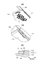
- FIG. 3 (A) is a perspective view of a wire harness
- FIG.3 (B) is a front view of a terminal crimping electric wire
- FIG.3 (C) is a perspective view of a housing.
- FIG. 4 (A) is a perspective view of the whole
- FIG.4 (B) is a top view which shows a terminal holding
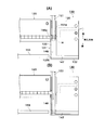
- FIG. 7 (A) is a front view
- FIG.7 (B) is a side view. It is a side view explaining an engagement confirmation means.
- FIG. 10A is an overall perspective view
- FIG. 10B is a perspective view showing a state where a housing is mounted on the guide of the tray
- FIG. 10C is a side sectional view of the guide. is there. It is a figure explaining the housing supply operation
- FIG. 3 An example of the wire harness manufactured with the terminal manufacturing apparatus of this invention is demonstrated.
- the wire harness P manufactured by the terminal insertion device of the present invention is as shown in FIG. 3 (A), and is shown in FIG. 3 (B), in which a terminal T is crimped to one end of an electric wire W.
- a terminal T of a crimped electric wire is inserted into a connector housing H shown in FIG.
- the terminal crimped electric wire is one in which a terminal T is crimped to one end of the electric wire W and solder S is attached to the other end.
- FIG. 3B the terminal crimped electric wire is one in which a terminal T is crimped to one end of the electric wire W and solder S is attached to the other end.
- a plurality of (in this example, 11) cavities C are formed in the housing H.
- each terminal T of the 11 terminal crimped electric wires W is inserted into the cavity C of the housing H.
- the wire harness P is manufactured by inserting each terminal T of the eleven terminal crimped electric wires W into the cavity C of the housing H.
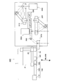
- FIG. 1 is a view (front view) of the terminal insertion device viewed from the terminal insertion direction
- FIG. 2 is a view (side view) of the terminal insertion device viewed from a direction orthogonal to the terminal insertion direction.
- the terminal insertion device 1 includes a terminal angle adjusting unit 10 that adjusts an angle around a wire axis of a terminal of a terminal crimped electric wire conveyed by a conveying device (not shown), and after the terminal angle is adjusted by the unit 10.
- a housing supply means 100 for supplying the housing to the housing holding means 180 and means 80 (see FIG. 2) for confirming the engagement between the terminal and the housing after the terminal is inserted into the cavity are provided.
- Each of these means is arranged on the machine base 3.
- the direction perpendicular to the paper surface indicates the electric wire insertion direction (electrical wire axial direction)
- the left-right direction indicates the direction (lateral direction) orthogonal to the electric wire insertion direction.
- FIG. 1 the direction perpendicular to the paper surface indicates the electric wire insertion direction (electrical wire axial direction)
- the left-right direction indicates the direction (lateral direction) orthogonal to the electric wire insertion direction.
- the left-right direction indicates the electric wire insertion direction
- the direction orthogonal to the paper surface indicates the direction (lateral direction) orthogonal to the electric wire insertion direction.
- the terminal side (right side in the figure) is referred to as the front direction (insertion direction, forward direction), and the opposite terminal side (left side in the figure) is referred to as the rear direction (reverse direction).
- an electric wire (see FIG. 3B) with a terminal crimped to the end is sent to the terminal angle adjusting means 10 by a conveying device (not shown), and the end of the electric wire is held by the means 10. .
- This position is referred to as an electric wire gripping position P1.
- the terminal angle adjusting means 10 rotates the electric wire by a predetermined angle in the axial direction as necessary.
- the electric wire is transferred to the terminal gripping / inserting means 20, and the end of the electric wire and the terminal are gripped.
- This height is referred to as a wire insertion height H.
- the housing is sent from the housing supply means 100 to the housing holding means 180.
- the housing is held at the insertion position P2 and the wire insertion height H by the housing holding means 180. Then, the terminal gripping / inserting means 20 moves to the insertion position P2, and the terminal is inserted into the cavity at a predetermined position of the housing. After insertion, the engagement confirmation means 80 confirms whether the housing and the terminal are engaged properly. After the predetermined number of terminal crimped electric wires are inserted into the housing, the housing (wire harness) into which the terminal crimped electric wires are inserted is discharged from the housing holding means 180.
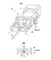
- the terminal angle adjusting means 10 will be described with reference to FIG.
- the terminal angle adjusting means 10 brings the pair of claw members 11 and 12 that grip the end portion of the electric wire W from the direction orthogonal to the electric wire axial direction and the claw members 11 and 12 closer to each other.
- the actuator 15 is moved in the direction to move and the direction to be separated, and the positioner 17 is rotated to rotate the actuator 15 around the electric wire axis direction.
- Each of the claw members 11 and 12 is a U-shaped member having an overall planar shape, and is disposed so that the U-shaped openings face each other and the front end surfaces 11a and 12a face each other.
- a convex portion 11b is formed on the tip surface 11a of one claw member 11, and a concave portion 12b into which the convex portion 11b is fitted is formed on the tip surface 12a of the other claw member 12.
- the notch is formed in the center of the height direction of both the end surfaces 11a and 12a. As shown in FIG. 4 (B), the end of the electric wire W on the terminal side is gripped between the notches of the both end faces 11a and 12a.
- an actuator called a parallel hand can be used as the actuator 15.
- the actuator 15 has a linear guide and two sliders that slide while engaging with the guide, and each slider approaches or separates in synchronization with the center.
- the base portions of the claw members 11 and 12 are fixed to the sliders. When both sliders approach, the tip surfaces 11a and 12a of the claw members 11 and 12 come into contact with each other to grip the electric wire W, and when separated, a gap opens between the tip surfaces 11a and 12a to release the electric wire W.
- the actuator 15 is connected to the rotation shaft of the positioner 17 and rotates around the gripped electric wire W. That is, the electric wire W held by the claw members 11 and 12 is rotated around the axis.
- the terminal crimping electric wire W is in a posture in which the terminal T is crimped by the terminal crimping apparatus (generally, both sides of the upper open U-shaped terminal are crushed inward. In many cases, it is inserted into the cavity of the housing with the posture and the pressure-bonding surface on the upper side. Also in the terminal insertion device 1 of the present invention, it is conveyed to the terminal angle adjusting means 10 in this posture.
- the crimping surface may be inserted with an inclination of 90 °, 180 ° or 270 ° with respect to the housing. Therefore, the terminal angle adjusting means 10 rotates the electric wire W by a desired angle.
- the terminal gripping / inserting means 20 is disposed above the terminal angle adjusting means 10 at the wire gripping position P1, as shown in FIGS.
- the means 20 includes an electric wire / terminal holding mechanism 30 that holds the end of the electric wire W and the terminal T.
- the electric wire / terminal holding mechanism 30 is supported so as to be movable in the vertical direction, the insertion direction, and the horizontal direction.
- the electric wire / terminal holding mechanism 30 descends to the terminal angle adjusting means 10 and holds the electric wire W held by the means 10. Thereafter, the electric wire W is raised to the electric wire insertion height H by the electric wire / terminal gripping mechanism 30, and is then conveyed in the lateral direction to the insertion position P2. Thereafter, the electric wire / terminal gripping mechanism 30 moves forward toward the housing held by the housing holding means 180, whereby the terminal is inserted into the housing.
- FIG. 5 is an exploded perspective view of the electric wire / terminal gripping mechanism
- FIG. 6 is a side view.
- the electric wire / terminal holding mechanism 30 includes a terminal claw 31 that holds the crimp terminal T of the electric wire W held by the terminal angle adjusting means 10 and an electric wire claw 61 that holds the end of the electric wire W.
- the terminal claws 31 are arranged on the front side, and the electric wire claws 61 are arranged on the rear side.
- the terminal claw 31 has a fixed claw member 32 and a movable claw member 33 that opens and closes with respect to the fixed claw member 32, and holds the terminal T from both sides in a direction orthogonal to the electric wire axial direction.
- the fixed claw member 32 is a plate-like member having a certain thickness, and the inner surface on the movable claw member side is a flat gripping surface.
- the fixed claw member 32 is fixed to an intermediate base 41 whose base is vertically long.
- the movable claw member 33 is also a plate-like member having a certain thickness, and is a flat grip surface facing the grip surface of the fixed claw member 32.
- the movable claw member 33 has a base fixed to the link member 34.
- the link member 34 is a member extending substantially horizontally from the base portion of the movable claw member 33, and an end portion on the side to which the movable claw member 33 is fixed is rotatably connected to the movable base 35 by a pin 36. .
- the tip of the rod 39 of the cylinder 38 is connected to the other end of the link member 34.
- the cylinder 38 is disposed on the intermediate base 41 so that the rod 39 extends downward.
- the movable base 35 is attached to the intermediate base 41 so as to be slidable up and down.
- An adjustment screw 43 extending in the vertical direction is attached to the intermediate base 41, and a slider (not shown) that engages with the adjustment screw 43 is attached to the back surface of the movable base 35.
- the slider moves up and down, and the movable base 35 moves up and down relative to the intermediate base 41.
- the upper limit height of the movable base 35 is regulated by a lock screw 44 attached to the intermediate base 41.
- the other end of the link member 34 is connected to the tip of the rod 39 of the cylinder 38 and thus does not move. For this reason, when the movable base 35 moves upward, the link member 34 rotates about the connection point with the tip of the rod 39, and the movable claw member 33 rotates in a direction to open with respect to the fixed claw member 32. . With this mechanism, it is possible to finely adjust the degree of opening when both the claw members 32 and 33 are closed.
- the intermediate base 41 is attached to the main base 47 so as to be slidable up and down.
- a cylinder 51 extending in the vertical direction is attached to the front surface of the main base 47 so that the rod 52 extends downward.
- a guide 54 extending in the vertical direction is attached to the main base 47.
- a slider 55 that engages with the guide 54 is attached to the back surface of the intermediate base 41.
- the tip of the rod 52 of the cylinder 51 is connected to the slider 55.
- the wire claw 61 includes a pair of claw members 62 and 63 that grip the end portion of the electric wire W from a direction orthogonal to the wire axis direction, and an actuator 65 that moves the claw members 62 and 63 toward and away from each other. And comprising. As shown in FIG. 6, each claw member 62, 63 has two gripping portions 62a and 62b, 63a and 63b that are arranged in the front and rear direction with a certain space in the direction of the electric wire axis. As the actuator 65, an actuator called a parallel hand can be used similarly to the terminal angle adjusting means 10 described above. That is, the actuator 65 has a linear guide and two sliders that slide while engaging with the guide, and each slider approaches or moves away from the center in synchronization.
- the base portions of the claw members 62 and 63 are respectively fixed to the slider.
- the inner surfaces of the gripping portions of the claw members 62 and 63 come into contact with each other to grip the electric wires W, and when they are separated, a gap opens between the inner surfaces of the gripping portions to release the electric wires W.
- the back surface of the actuator 65 is attached to the attachment plate 67 so that the height can be adjusted.
- the mounting plate 67 is fixed to the main base 47 by left and right side plates 68 and 69. That is, the actuator 65 and the electric wire claw 61 are fixed to the main base 47. Accordingly, the terminal claw 31 can move in the vertical direction with respect to the main base 47 by the above-described configuration, but the wire claw 61 cannot move in the vertical direction with respect to the main base 47. With such a configuration, the terminal claw 31 and the electric wire claw 61 can be opened and closed independently, and the terminal claw 31 can move up and down with respect to the electric wire claw 61.
- a holding surface moves between the same lower position as the height of the holding surface of the electric wire nail
- the electric wire / terminal gripping mechanism 30 is supported by an elevating linear actuator 71 so as to be movable in the vertical direction.
- the elevating linear actuator 71 includes, for example, a ball screw that is rotated by a motor, a slider that engages with the screw, and a guide that guides the slider in a straight line.
- the elevating linear actuator 71 is arranged so that the ball screw extends in the vertical direction, and the back surface of the main base 47 of the electric wire / terminal gripping mechanism 30 is fixed to the slider.
- the slider moves up and down along the ball screw. That is, the entire wire / terminal gripping mechanism 30, that is, the terminal claw 31 and the wire claw 61 are simultaneously moved up and down.
- the heights of the gripping portions of the terminal claws 31 and the electric wire claws 61 are the same lower position as the terminal gripping height of the terminal angle adjusting mechanism 10 and the same upper position as the insertion position height H of the housing holding means 180.
- the electric wire W is transferred from the terminal angle adjusting means 10 to the electric wire / terminal gripping mechanism 30.
- the insertion position height H may be changed depending on the number of cavities in the housing. In this case, the insertion position height H can be arbitrarily set by the elevating linear actuator 71.
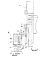
- FIG. 7A is a front view and FIG. 7B is a side view.
- the tip surfaces of the claw members 11 and 12 of the terminal angle adjusting means 10 in the electric wire axial direction are The claw member 61 of the electric wire / terminal gripping mechanism 30 is positioned between the front gripping portions 62a and 63a and the rear gripping portions 62b and 63b.
- the electric wire W is held by the electric wire claw 61 of the electric wire / terminal holding mechanism 30 at two places in the front-rear direction, and the terminal T is held by the terminal claw 31. Even if the claw members 11 and 12 of the terminal angle adjusting means 10 are rotated, the claws 31 and 61 of the electric wire / terminal holding means 30 are both connected to the terminal angle adjusting means 10 as shown in FIG. Since the space between the claw members 11 and 12 moves up and down, rotation of the claw members 11 and 12 is not hindered.
- the wire / terminal gripping mechanism 30 and the lifting linear actuator 71 are supported by an insertion linear actuator 77 so as to be able to advance and retract in the insertion direction (wire axis direction).
- the traveling direction (front) indicates the right direction in FIG. 2 and is a direction in which the terminal is inserted into the cavity of the housing.
- the backward direction (rear) indicates the left direction in FIG. 2 and is a direction in which the electric wire is pulled out from the housing.
- the insertion linear actuator 77 includes a mechanism 80 (described later in detail) for confirming the engagement between the terminal and the housing after the terminal is inserted into the cavity.
- This linear actuator 77 for insertion is also composed of a ball screw rotated by a motor, a slider engaged with the screw, and a guide for guiding the main slider in a straight line, and is arranged to extend in the insertion direction.
- a substantially L-shaped plate 73 having a vertical piece 73a and a horizontal piece 73b is fixed to the rear surface of the elevating linear actuator 71.
- the vertical piece 73a of the plate 73 is fixed to the actuator 71, and the horizontal piece 73b extends forward in the insertion direction.
- An engagement confirmation mechanism 80 is disposed between the horizontal piece 73b and the slider of the insertion linear actuator 73.
- the advance / retreat operation of the electric wire / terminal gripping mechanism 30 will be described.
- the insertion linear actuator 77 is driven to move the slider forward or backward, the plate 73, the lift linear actuator 71 fixed to the plate 73, and the lift linear actuator 71 are supported via the engagement confirmation mechanism 80.
- the electric wire / terminal gripping mechanism 30 is moved forward and backward.
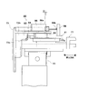
- the engagement confirmation mechanism 80 will be described with reference to FIG.
- the engagement confirmation mechanism 80 includes a base 81 extending in the insertion direction, a small slider 82 that engages and slides on the base 81, and a cylinder 83 that relatively moves the slider 82 back and forth in the insertion direction.
- the small slider 82 is fixed to the lower surface of the horizontal piece 73 b of the plate 73.
- a base 81 with which the small slider 82 is engaged is fixed to the slider 77 a of the insertion actuator 77.
- the cylinder 83 is disposed so that the rod 84 extends forward, and is fixed to the lower surface of the horizontal piece 73b.
- the end of the base 81 is connected to the tip of the rod 84.
- a contact type displacement sensor 86 for example, a contact type digital sensor (accuracy 3 ⁇ m, resolution 1 m)
- the displacement sensor 86 includes a main body 86a and a contact 86b that is biased forward by a spring with respect to the main body 86a.
- the displacement sensor 86 is disposed such that the contact 86b faces the front.
- a reference plate 88 is erected from the base 81 so as to face the contact 86b.
- the contact 86b of the sensor 86 is in contact with the surface of the reference plate 88 in a state where the spring is contracted (a state where the contact 86b is pushed by the reference plate 88 and pushed into the main body 86b).
- the spring expands and contracts according to the same distance, and the distance between the contact 86b of the sensor 86 and the main body 86a changes.
- the cylinder 83 (low friction cylinder) is attached to the lower surface of the horizontal piece 73b of the plate 73 as described above. In this example, it is preferable to use a low friction cylinder with low sliding resistance (output control of about 0.01 N unit is possible).
- a forward force is applied to the base 81.
- the slider 77a of the insertion linear actuator 77 to which the base 81 is fixed is immovable with respect to the ball screw, and conversely, a backward force is applied to the cylinder 83. That is, the plate 73 to which the cylinder 83 is fixed tends to move backward with respect to the insertion linear actuator 77.
- the main body portion 86a of the sensor 86 fixed to the horizontal piece 73b of the plate 73 also moves backward.
- the reference plate 88 in contact with the contact 86b of the sensor 86 is erected on the base 81 fixed to the slider 77a that does not move. If 86a moves backward, the space
- the contact 86b is always urged so as to contact the reference plate 88, the distance between the contact 86b and the main body 86a is increased. Therefore, an alarm is issued when the displacement D of the main body 86a is equal to or greater than a predetermined value.
- a certain rearward force (to pull out the electric wire W from the housing) is applied to the electric wire / terminal holding mechanism 30 that holds the electric wire W by the mechanism 80.
- the force to be pulled out is too large, there is a possibility of forcibly pulling out a normally inserted terminal, so the force to be pulled out is as small as possible and stable within a small range.
- the cylinder 83 that applies the force to be pulled out should be a low friction cylinder as described above, and the force to be pulled out must be set arbitrarily and stably.
- the insertion linear actuator 77 is supported by a transfer linear actuator 91 extending in the horizontal direction (wire transfer direction) so as to be movable in the horizontal direction.
- the conveyance linear actuator 91 is also composed of a ball screw rotated by a motor, a slider engaged with the screw, and a guide for guiding the main slider in a straight line.
- a plate 78 is fixed to the lower surface of the insertion linear actuator 77, and the plate 78 is fixed to the slider of the conveyance linear actuator 91.
- the transfer actuator 91 moves the insertion linear actuator 77, that is, the electric wire / terminal holding means 20, from the electric wire gripping position P1 (terminal angle adjusting means) toward the left in FIG. To the holding means).
- the housing holding means 180 is arranged on the side of the terminal angle adjusting means 10 (the direction opposite to the direction in which the terminal crimping electric wire is conveyed to the terminal angle adjusting means 10).
- the housing holding means 180 is disposed on the opposite side of the terminal angle adjusting means 10.
- the housing supply means 100 will be described with reference to FIGS. As shown in FIG. 9, the housing supply unit 100 has confirmed that the tray 110 in which a large number of housings are accommodated, the linearly-advanced part feeder 120 continuing to the tray 110, and the housing being supplied from the parts feeder 120. And a feed mechanism 130 for transporting the housing to the housing holding means.
- the tray 110 has a flat shape, and a large number of housings H are accommodated so as to spread in a flat state.
- a guide 111 is formed on one side (front side) of the tray 110.
- the side surface shape of the guide 111 has a shape that matches the side surface shape in the insertion posture of the housing H.
- the housing H applied to the insertion device of this embodiment includes a front surface H1 in which a cavity C is formed, a projecting piece H2 projecting forward from the upper edge of the front surface H1, and a front surface.
- the guide 111 has a stepped portion 112 on which the projecting piece H2 is placed, a wall portion 113 against which the front surface H1 is applied, and a groove portion 114 into which the front protrusion H3 is fitted.
- the housing H accommodated in the tray 110 When the housing H accommodated in the tray 110 is appropriately taken out and positioned on the guide 11, the housing H contacts the front surface H ⁇ b> 1 with the wall portion 113 so that the protruding piece H ⁇ b> 2 rides on the stepped portion 112, and further, the front protrusion
- the guide 111 is engaged only in a posture in which H3 is fitted in the groove 114 (a posture in which the front surface H1 faces rearward in the insertion direction, hereinafter referred to as rearward). That is, the housing H can always be mounted on the guide 111 in the same posture.
- the rectilinear parts feeder 120 is continuously arranged at the outlet 111 a of the guide 111 of the tray 110. If the housing H arranged in the guide 111 is pushed toward the parts feeder 120, the housing H is inserted from the outlet 111 a of the guide 111 of the tray 110 into the inlet of the parts feeder 120.
- the parts feeder 120 conveys the housing H in the counter-tray direction (right direction in the figure).
- a housing feeding mechanism 130 is disposed at the outlet of the parts feeder 120.
- the housing feed mechanism 130 will be described with reference to FIGS. 11, 12, and 13.
- 11 and 12 are plan views showing the structure of the housing feed mechanism 130.
- FIG. FIG. 13 is an exploded perspective view.
- the housing feeding mechanism 130 supplies the housing H to the housing holding means 180 after confirming that the housing H is reliably supplied.
- the housing feeding mechanism 130 includes a feed base 131 in which a passage is formed in which the housing H is conveyed in the above-described posture (backward posture), and two rods 151 and 153 that feed the housing along the passage.
- the feed base 131 is a rectangular parallelepiped block and has a flat upper surface 133 surrounded by an outer wall 132.
- the height of the upper surface 133 is equal to the height of the outlet of the parts feeder 120.
- a flat rectangular parallelepiped block 135 having a size slightly smaller than the planar shape of the feed base 131 is disposed slightly inside the outer wall 132 of the upper surface 133.
- the block 135 has a housing defined by the side surface of the block 135 and the side wall 132 of the feed base 131 on the side of the parts feeder side and the front side of the feed base 131.
- a passage is formed.
- the passage is L-shaped and has a longitudinal passage 146 extending in the insertion direction and a transverse passage 147 extending in the lateral direction substantially orthogonal to the longitudinal passage 146.
- the width of the vertical passage 146 is substantially equal to the lateral length of the housing H, and the width of the lateral passage 147 is substantially equal to the length of the housing H in the depth direction.
- the outlet of the lateral passage 147 faces the housing holding means 180.
- the side wall 132 of the part facing the outlet of the parts feeder 120 is formed with a notch 132 a serving as the inlet of the housing, and the housing H is cut from the passage of the parts feeder 120. It is supplied to the vertical passage 146 through the notch 132a.
- the housing H is in the posture of being attached to the guide 111 of the tray 110, and the front surface H1 in which the cavity C is formed is in the backward posture. With this posture, the housing H advances forward through the vertical passage 146 and then advances rightward through the horizontal passage 147.
- a longitudinal push rod 151 for feeding the housing H is disposed in the longitudinal passage 146 so as to be extendable and contractible.
- a groove 151 a in which the housing H is accommodated is formed on the lower surface of the distal end portion of the vertical push rod 151.
- the vertical push rod 151 expands and contracts by being driven by a cylinder (not shown) between a standby position where the groove 151 a faces the notch 132 a of the side wall 132 and an extended position where the longitudinal path 146 reaches the most distal end.
- a lateral push rod 153 for feeding the housing H is arranged to be extendable and contractible.
- a cutout 132 b is formed in the side wall 132 of the lateral passage 147 opposite to the housing holding means 180.
- the lateral push rod 153 is disposed on the side of the lateral passage 147 of the feed base 131 and enters the passage 147 through the notch 132b.
- the lateral push rod 153 extends and contracts between a standby position where the tip is located outside the notch 132 b of the side wall 132 and an extended position that penetrates the lateral passage 147 and reaches the housing holding means 180.
- the expansion / contraction distance of the lateral push rod 153 is relatively long, and after passing through the lateral passage 147 of the feed base 131, as will be described later, between the guide grooves 181a and 182a of the housing holding means 180 (see FIG. 14).
- the two cylinders 155 and 157 are configured to expand and contract in two stages as shown in FIG. That is, it is possible to perform a two-stage operation in which each cylinder passes through the lateral passage 147 of the feed base 131 and the other cylinder passes between the guide grooves of the housing holding means 180 by the stroke distance. Is preferable in terms of easy adjustment.
- the housing H supplied from the parts feeder 120 is conveyed as follows.
- the vertical rod 151 stands by at the standby position in the vertical passage 146
- the horizontal rod 153 also stands by at the standby position outside the side wall 132.
- the housing H is in the groove 151a of the vertical rod 151 in the vertical passage 146. Is housed.
- the vertical rod 151 extends to the extended position, and the housing H is conveyed to the tip of the vertical passage 146.
- the horizontal rod 153 extends into the horizontal passage 147.
- the side of the housing H in the groove 151a of the vertical rod 151 is pushed by the horizontal rod 153 and proceeds in the horizontal passage 147 in the rearward posture.
- FIG. It is sent from the lateral passage 147 to the housing holding means 180.
- the housing feed mechanism 130 includes a housing detection mechanism 140 that detects the housing H supplied from the parts feeder 120.
- the housing detection mechanism 140 will be described with reference to FIG.
- the block 135 has a flat rectangular parallelepiped shape, and a stepped portion 136 protruding outward is formed on the side surface on the part feeder side.
- the height of the stepped portion 136 is about half of the height of the block 135.
- a small-diameter through hole 137 is formed at a position on the outer surface of the step portion 136 facing the notch 132a of the outer wall 132 of the feed base 131.
- a groove 138 is formed on the lower surface of the block 135 so as to cross the block 135.
- the small diameter through hole 137 communicates with the groove 138.
- a tunnel-shaped passage is formed between the groove 138 and the upper surface 133 of the feed table 131.
- the end of the groove 138 communicates with a through hole 141 formed in the feed base 131.
- a pipe 161 extending from a negative pressure generator 160 (for example, a vacuum ejector) is connected to the through hole 141.
- a negative pressure generator 160 for example, a vacuum ejector
- the outlet of the small diameter through hole 137 is closed by the housing H, and a negative pressure is maintained in these through holes.
- the outlet of the small-diameter through hole 137 remains open, and the inside of the through hole remains at atmospheric pressure.
- a negative pressure generator 162 (for example, a digital pressure sensor) is attached to the negative pressure generator 160, and the pressure in the through hole is detected.
- the detection range of the pressure sensor 162 in this example is ⁇ 101.3 kPa to 1 MPa.
- the detected pressure is determined by a control unit (not shown), and if the pressure is lower than an arbitrarily set pressure (for example, ⁇ 10 KPa or lower), it can be detected that the housing is supplied to a predetermined position.
- the housing H needs to be in contact with the outer surface of the stepped portion 136 so as to block the outlet of the small-diameter through-hole 137. If the gap between the two is too large, the negative pressure cannot be maintained. The presence of the housing H can be detected.
- the housing detection means 140 detects the presence of the housing at the end portion of the parts feeder 120. Thus, by detecting at the terminal part of the parts feeder 120, it can utilize as an operation start signal of the housing feed mechanism in the next process.
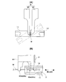
- the housing holding means 180 includes a pair of guide members 181 and 182 that sandwich the housing H from above and below, an actuator 185 that moves the guide members 181 and 182 in directions toward and away from each other, and an actuator 185 in the terminal insertion direction. And a positioner 187 that rotates around.
- a conveyor (not shown) for carrying out the manufactured wire harness is disposed below the housing holding means 180.
- the guide members 181 and 182 are flat rectangular parallelepiped members, and laterally extending guide grooves 181a and 182a for guiding the housing H are formed on opposing inner surfaces.
- One end of the guide grooves 181a and 182a (left side in FIG. 14A) is arranged so as to be continuous with the outlet of the lateral passage 147 of the feed base 131.
- the most distal ends (right end in the figure) of the guide grooves 181a and 182a are the housing holding position (terminal insertion position P2).
- This actuator 185 can also use an actuator called a parallel hand.
- This actuator has a linear guide and two sliders that slide while engaged with the guide, and each slider approaches or moves away from the center in synchronization.
- Each guide member 181 and 182 is fixed to a slider. When both sliders approach, the housing H is held between the guide grooves 181a and 182a of the guide members 181 and 182. However, the front surfaces of the guide members 181 and 182 are not completely in contact with each other, and there is a clearance between both the front surfaces so that the cavity C of the housing H is exposed. When the guide members 181 and 182 are separated from each other, a clearance is opened between the guide grooves 181a and 182a of the guide members to release the housing H.
- the actuator 185 is connected to the rotation shaft of the positioner 187, and rotates, for example, 90 ° around the wire axis. That is, the direction of the guide grooves 181a and 182a can be directed from the horizontal direction to the vertical direction. After the guide grooves 181a and 182a are rotated so as to be in the vertical direction, when the guide members 181 and 182 are separated from each other, the housing H (wire harness) after the terminal is inserted is separated from the guide members 181 and 182 by its own weight. Drop onto the conveyor.
- the housing holding means 180 is rotated 90 °, the guide members 181 and 182 are opened, and the housing H is dropped by its own weight.
- a delivery head 191 is supported above the housing holding means 180 so as to be movable up and down.
- the delivery head 191 is attached to the tip of the rod 193 of the cylinder 192 disposed in the vertical direction, and the rear of the housing holding means 180 is accompanied with the expansion and contraction of the cylinder 192. Is moved up and down between a lower position (indicated by an imaginary line in FIG.
- the housing H accommodated in the tray 110 shown in FIG. 10A is attached to the guide 111 of the tray 110 by the operator's manual work.
- the front surface of the housing H is attached to the guide 111 in a rearward posture in the insertion direction.
- the housings H can be arranged in a predetermined posture without using a nerve.
- the housing H In the parts feeder 120, the housing H is fed toward the feeding mechanism 130. And finally, as shown in FIG. 11, it fits into the groove
- FIG. In the groove 151a as described in FIG. 13, air is sucked from the small diameter through hole 137 of the block 135, and if the housing H exists in the groove 151a, the opening of the small diameter through hole 137 is blocked.
- the vertical rod 151 extends in the vertical passage 146 to the tip.
- the housing H moves forward in the vertical passage 146 with the front surface H1 being in the rearward posture.
- the horizontal rod 153 is extended, and the housing H is pushed out from the groove 151a of the vertical rod 151 into the horizontal passage 147 and conveyed in the horizontal passage 147 as it is.
- the housing H moves in the lateral passage 147 while keeping the rearward posture.
- the lateral rod 153 further extends, and conveys the housing H from the feed base 131 in the guide grooves 181a and 181b of the guide members 181 and 182 of the housing holding means 180 to the innermost part (insertion position P2). Thereafter, the lateral rod 153 contracts, and the guide members 181 and 182 of the housing holding means 180 approach to hold the housing H immovable at the insertion position P2.
- the wire W is transported to the terminal angle adjusting means 10 by a transport device (not shown) (reference numeral 370 in FIG. 17).
- the electric wire W is conveyed in a posture in which the crimped terminal T faces the rearward direction and the crimping surface is generally upward.
- the electric wire W at the end portion on the crimp terminal side is held between both the claw members 11 and 12.
- the terminal angle adjusting means 10 since the terminal T is inserted into the cavity of the housing as it is, it is not necessary to adjust the terminal angle by the terminal angle adjusting means 10.
- the terminal angle adjusting means 10 rotates the electric wire by a desired angle.
- the lifting linear actuator 71 is driven, the wire / terminal gripping mechanism 30 is lowered, and the terminal T of the wire W held by the terminal angle adjusting means 10 and the two ends of the wire end are connected. Grab.
- the electric wire claw 61 holds the electric wire W before and after the claw members 11 and 12 of the terminal angle adjusting means 10.
- the claw members 11 and 12 of the terminal angle adjusting means 10 are opened, and the electric wire W is transferred to the electric wire / terminal holding mechanism 30.
- the lifting linear actuator 71 is driven, and the electric wire / terminal gripping mechanism 30 is raised to hold the electric wire at the insertion height H.
- the conveyance actuator 91 is driven, and the electric wire / terminal gripping mechanism 30 is conveyed to the insertion position P2 (housing holding means 180).
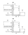
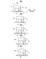
- the terminal insertion operation will be described with reference to FIG.
- the terminal T of the electric wire held by the electric wire claw 61 and the terminal claw 31 of the electric wire / terminal holding mechanism 30 and the cavity position of the housing H are positioned.
- the insertion actuator 77 is driven to advance the electric wire / terminal gripping mechanism 30 in the forward / backward direction, and first, the front end of the terminal T is inserted into the cavity of the housing H as shown in FIG. .
- FIG. 15C the terminal claw 31 of the electric wire / terminal gripping mechanism 30 is opened, and only the terminal claw 31 is raised. In this state, the electric wire W is held only by the electric wire claw 61.
- the insertion actuator 77 is further driven, and the wire / terminal gripping mechanism 30 is further advanced in the forward / backward direction as shown in FIG. 14 (D), whereby the entire terminal T is inserted into the cavity of the housing H. Is done.
- the terminal claw 31 also moves forward while being opened and raised. As a result, the terminal T is inserted into the cavity of the housing H and engages with the cavity.
- the rod 84 of the cylinder 83 of the engagement confirmation means 80 extends to apply a backward force to the small guide 82. Since the slider of the insertion linear actuator 77 to which the small guide 82 is fixed is immovable with respect to the ball screw, a forward force is applied to the cylinder 83. That is, a backward force is applied to the plate 73 to which the cylinder 83 is fixed, that is, the electric wire / terminal gripping mechanism 30 fixed to the plate 73, and as shown in FIG. An attempt is made to pull out the terminal T engaged with the housing H in an attempt to move backward.
- the pulling force is set to be equal to or less than the force with which the terminal is pulled out from the housing in a normal engagement state. If the engagement between the terminal and the cavity is sufficient, the plate 73 does not move even when such a force is applied. However, if this engagement is insufficient, the terminal is removed from the cavity and the plate 73 moves forward. Then, the main body portion 86a of the sensor 86 attached to the plate 73 is displaced from the initial state, and when the displacement becomes a predetermined interval or more (for example, 0.1 mm or more), an alarm is issued by a sound or a display device. In the present invention, since the contact type sensor 86 as described above is used, it is possible to detect a minute displacement.
- the engagement confirmation mechanism by pulling out the terminal is provided separately from the terminal insertion mechanism.
- the terminal insertion mechanism a relatively strong force is required to insert the terminal into the housing, but it is preferable that the force to be pulled out in the engagement confirmation work is as small as possible and stable within a small range. .
- the force to be pulled out in the engagement confirmation work is as small as possible and stable within a small range. .
- the engagement confirmation work since the terminal is inserted or pulled out in the axial direction of the electric wire, it is possible to use one actuator that can be driven in the opposite direction. Since the force applied to the terminal is greatly different from the engagement confirmation work, it is preferable to separate these mechanisms.
- This terminal insertion operation is performed 11 times, which is the number of cavities in the housing in this example.
- the terminal is positioned by the transfer actuator 91 and the insertion actuator 77 for each position of the cavity of the housing.
- a housing holding means rotates 90 degrees.
- the guide grooves 181a and 182a are oriented vertically.
- the actuator 185 is driven, the guide members 181 and 182 are separated, and the housing is released. Further, as shown in FIG.
- the rod 193 of the cylinder 192 extends and the delivery head 191 descends to push the wire bundle extending from the housing sandwiched between the guide members 181 and 182 downward.
- the extruded housing (wire harness P) falls on the conveyor and is collected.
- FIG. 17 is a plan view schematically showing the configuration of the wire harness manufacturing apparatus.
- This apparatus manufactures the wire harness shown in FIG.
- the wire harness manufacturing apparatus 300 includes an electric wire feeding device 310 that feeds and clamps an electric wire from a wire bundle, a cut and strip device 320 that peels off and covers the electric wire, and a cut electric wire (cut electric wire).
- a tail clamp device 330 that clamps an end on the base end side (front side in the insertion direction) and an end portion on the distal end side (rear side in the insertion direction) of the electric wire (residual electric wire) clamped on the wire feeding device 310
- a solder bath 340 for soldering for soldering, a terminal crimping device 350 for crimping a terminal to the proximal end of the cut wire clamped by the tail clamp device 330, a wire dispensing device 360 with both ends processed,
- a terminal insertion device 1 that inserts a terminal crimped to the proximal end into the housing, and a conveyance device that conveys an electric wire from the dispensing device 360 to the terminal insertion device 1.
- the vertical direction of FIG. 17 shows the electric wire axial direction, and shows the insertion direction when the electric wire is inserted into the housing.
- the upward direction in the figure indicates the forward direction (front direction), and the downward direction indicates the backward direction (rear direction). Since the wire feeding device, the clamp device, the terminal crimping device, the solder bath, etc., which are used in a normal wire harness manufacturing device can be used, detailed description of each device is omitted.
- the electric wire is fed from the electric wire feeder 310 toward the tail clamp device by a predetermined length, and is clamped by the same device.
- the tip of the electric wire is soldered in the previous step.
- the electric wire is cut by the cut / strip device 320.
- the electric wire (residual electric wire) remaining in the electric wire feeder 310 is clamped by the electric wire feeder 310, and the cut electric wire (cut electric wire) is clamped by the tail clamp device 330.
- the wire feeding device 310 is swung, and the coating of the end portion of the remaining electric wire is peeled off by the cut / strip device 320. Further, the wire feeding device 310 is swung to the solder bath 340, and the tip portion from which the covering has been peeled is removed. Soldered. Thereafter, the wire feeder 310 returns to the original position.
- the tail clamp device 330 is turned, and the cutting / strip device 320 peels off the coating of the front end of the cut wire, and further turns to the terminal crimping device 350 to remove the coating.
- a terminal is crimped to the part.
- the electric wire is transferred from the tail clamp device 330 to the dispensing device 360. That is, at this stage, the terminal crimped electric wire shown in FIG. 3B, in which the terminal is crimped to one end and the other end is soldered, is manufactured.
- this terminal crimped electric wire is conveyed by the conveying device 370 to the terminal insertion device 1 described with reference to FIG. And the terminal is inserted in the housing by the device 1, and the wire harness P shown in FIG. 3A (the wire harness in which one end is inserted into the housing and the other end is soldered) Manufactured.
- a terminal crimping device can be provided instead of the solder bath 340.
- a terminal is crimped to the tip of the residual electric wire. That is, at the stage of paying out by the payout device 370, a terminal crimped electric wire having terminals crimped at both ends is manufactured. Then, one terminal is inserted into the housing by the insertion device. As a result, a wire harness in which one end is inserted into the housing and a terminal is crimped to the other end is manufactured.
Landscapes
- Engineering & Computer Science (AREA)
- Manufacturing & Machinery (AREA)
- Manufacturing Of Electrical Connectors (AREA)
Abstract
L'invention a pour objet un dispositif d'insertion de borne ou similaire capable de fournir des faisceaux électriques de diverses formes, ou permettant une vérification de qualité d'installation de borne et une alimentation fiable et rapide d'un logement. Pour ce faire, l'invention propose un dispositif d'insertion de borne (1) comportant un moyen de maintien-insertion de borne (20) permettant de maintenir et d'insérer des bornes dans des cavités d'un logement, un moyen de retenue de logement (180), et un moyen (10) permettant d'ajuster l'angle des bornes par rapport à la direction axiale de fils électriques lorsque le moyen de maintien-insertion de borne (20) maintient les bornes. Du fait que l'angle des bornes par rapport à la direction axiale des fils électriques (direction de vrillage des fils électriques) est ajusté par le moyen d'ajustement d'angle de borne (10), les bornes peuvent être insérées avec le plan de sertissage incliné à 90°, 180° ou 270° par rapport au logement.
Priority Applications (3)
| Application Number | Priority Date | Filing Date | Title |
|---|---|---|---|
| PCT/JP2011/055213 WO2012120611A1 (fr) | 2011-03-07 | 2011-03-07 | Dispositif d'insertion de borne, dispositif de fabrication de faisceau électrique, dispositif de détection d'article et procédé d'insertion de borne, procédé de fabrication de faisceau électrique et procédé de détection d'article |
| CN201180069088.7A CN103415966B (zh) | 2011-03-07 | 2011-03-07 | 端子插入装置、线束制造装置及端子插入方法 |
| JP2012506831A JP5048885B1 (ja) | 2011-03-07 | 2011-03-07 | 端子挿入装置、ワイヤーハーネス製造装置、物品検出装置、及び、端子挿入方法、ワイヤーハーネス製造方法、物品検出方法 |
Applications Claiming Priority (1)
| Application Number | Priority Date | Filing Date | Title |
|---|---|---|---|
| PCT/JP2011/055213 WO2012120611A1 (fr) | 2011-03-07 | 2011-03-07 | Dispositif d'insertion de borne, dispositif de fabrication de faisceau électrique, dispositif de détection d'article et procédé d'insertion de borne, procédé de fabrication de faisceau électrique et procédé de détection d'article |
Publications (1)
| Publication Number | Publication Date |
|---|---|
| WO2012120611A1 true WO2012120611A1 (fr) | 2012-09-13 |
Family
ID=46797618
Family Applications (1)
| Application Number | Title | Priority Date | Filing Date |
|---|---|---|---|
| PCT/JP2011/055213 Ceased WO2012120611A1 (fr) | 2011-03-07 | 2011-03-07 | Dispositif d'insertion de borne, dispositif de fabrication de faisceau électrique, dispositif de détection d'article et procédé d'insertion de borne, procédé de fabrication de faisceau électrique et procédé de détection d'article |
Country Status (3)
| Country | Link |
|---|---|
| JP (1) | JP5048885B1 (fr) |
| CN (1) | CN103415966B (fr) |
| WO (1) | WO2012120611A1 (fr) |
Cited By (5)
| Publication number | Priority date | Publication date | Assignee | Title |
|---|---|---|---|---|
| JP2018101606A (ja) * | 2016-10-03 | 2018-06-28 | コマックス ホルディング アクチエンゲゼルシャフトKomax Holding Ag | ケーブルハーネスの予め組み立てられたケーブル端部を正しい回転位置に位置合わせする方法および装置 |
| CN109713545A (zh) * | 2017-10-25 | 2019-05-03 | 泰科电子(上海)有限公司 | 装配系统和装配方法 |
| CN113451863A (zh) * | 2020-03-26 | 2021-09-28 | 矢崎总业株式会社 | 用于制造具有端子的电线的装置和方法 |
| CN114665354A (zh) * | 2022-05-20 | 2022-06-24 | 四川省蜀锦工贸有限责任公司 | 一种线缆端部壳体的组装装置 |
| CN116073214A (zh) * | 2022-11-30 | 2023-05-05 | 江苏科瑞恩科技股份有限公司 | 端子组件加工线 |
Families Citing this family (18)
| Publication number | Priority date | Publication date | Assignee | Title |
|---|---|---|---|---|
| JP6044533B2 (ja) * | 2013-12-26 | 2016-12-14 | 住友電装株式会社 | 端子挿入装置及び配線モジュールの製造方法 |
| CN103745781B (zh) * | 2013-12-31 | 2016-01-27 | 东莞市胜蓝电子有限公司 | 换线装置 |
| JP6276095B2 (ja) * | 2014-04-04 | 2018-02-07 | 矢崎総業株式会社 | 端子挿入装置及び端子挿入方法 |
| CN104374537B (zh) * | 2014-11-27 | 2017-04-12 | 惠州住成电装有限公司 | 一种全方位线束疲劳测试治具 |
| KR20170088991A (ko) * | 2014-12-04 | 2017-08-02 | 쉴로이니게르 홀딩 아게 | 피복이 벗겨진 케이블의 단부에 요소를 끼워맞춤하는 방법 |
| CN104407398B (zh) * | 2014-12-22 | 2017-02-22 | 天津长城精益汽车零部件有限公司 | 一种线束用塑件内端子安装检测装置 |
| CN105717332A (zh) * | 2016-04-06 | 2016-06-29 | 江苏雷特电机股份有限公司 | 一种电抗器连接装置 |
| CN107346857B (zh) * | 2016-05-05 | 2018-11-27 | 沈阳新松机器人自动化股份有限公司 | 一种机器人自动插线束端子的装置及其插线束端子方法 |
| JP6352973B2 (ja) * | 2016-05-31 | 2018-07-04 | 矢崎総業株式会社 | ワイヤハーネスの製造方法及び製造装置 |
| CN106410570B (zh) * | 2016-11-11 | 2019-02-15 | 深圳市顺科线束设备有限公司 | 连接器端子自动插入胶壳设备及其加工方法 |
| CN106442144B (zh) * | 2016-11-11 | 2023-08-29 | 深圳市顺科达智能装备有限公司 | 连接器端子插入胶壳拉力测试装置及其测试方法 |
| CN108832463B (zh) * | 2018-05-08 | 2023-08-29 | 深圳市顺科达智能装备有限公司 | 一种全自动单头插入机 |
| CN109434409B (zh) * | 2018-12-21 | 2023-10-13 | 东莞市混沌电子科技有限公司 | 一种穿外壳机构及其穿外壳方法 |
| CN110011163B (zh) * | 2019-04-30 | 2024-04-05 | 东莞市锐华自动化设备有限公司 | 连接线端子插胶壳装置及方法 |
| WO2020241270A1 (fr) * | 2019-05-30 | 2020-12-03 | 新明和工業株式会社 | Dispositif de traitement de câble électrique |
| CN110676770B (zh) * | 2019-09-10 | 2024-11-08 | 合肥中科蓝睿科技有限公司 | 一种零位基准调节装置 |
| CN112985795B (zh) * | 2021-02-26 | 2023-06-16 | 广东亚泰科技有限公司 | 装配检测装置及线束加工设备 |
| CN119253385B (zh) * | 2024-10-18 | 2025-10-28 | 深圳市林全科技有限公司 | 端子线双端校正装置及校正方法 |
Citations (3)
| Publication number | Priority date | Publication date | Assignee | Title |
|---|---|---|---|---|
| JPH0831542A (ja) * | 1994-07-21 | 1996-02-02 | Yazaki Corp | 端子付き電線の反転,移載方法及び装置 |
| JP2004158347A (ja) * | 2002-11-07 | 2004-06-03 | Sumitomo Wiring Syst Ltd | 端子固定状態検査装置及び方法 |
| JP2008010375A (ja) * | 2006-06-30 | 2008-01-17 | Japan Automat Mach Co Ltd | ワイヤハーネス製造装置 |
Family Cites Families (4)
| Publication number | Priority date | Publication date | Assignee | Title |
|---|---|---|---|---|
| CN2553538Y (zh) * | 2002-07-18 | 2003-05-28 | 昆荣机械股份有限公司 | 端子插入机 |
| JP4917418B2 (ja) * | 2006-12-14 | 2012-04-18 | タイコエレクトロニクスジャパン合同会社 | 端子挿入装置 |
| CN101542851B (zh) * | 2007-01-16 | 2011-12-21 | 日本自动机械株式会社 | 端子压接方法、端子压接装置以及端子压接电线制造装置 |
| CN101764338A (zh) * | 2008-12-25 | 2010-06-30 | 三菱电线工业株式会社 | 连接器用端子安装用具 |
-
2011
- 2011-03-07 CN CN201180069088.7A patent/CN103415966B/zh active Active
- 2011-03-07 WO PCT/JP2011/055213 patent/WO2012120611A1/fr not_active Ceased
- 2011-03-07 JP JP2012506831A patent/JP5048885B1/ja active Active
Patent Citations (3)
| Publication number | Priority date | Publication date | Assignee | Title |
|---|---|---|---|---|
| JPH0831542A (ja) * | 1994-07-21 | 1996-02-02 | Yazaki Corp | 端子付き電線の反転,移載方法及び装置 |
| JP2004158347A (ja) * | 2002-11-07 | 2004-06-03 | Sumitomo Wiring Syst Ltd | 端子固定状態検査装置及び方法 |
| JP2008010375A (ja) * | 2006-06-30 | 2008-01-17 | Japan Automat Mach Co Ltd | ワイヤハーネス製造装置 |
Cited By (8)
| Publication number | Priority date | Publication date | Assignee | Title |
|---|---|---|---|---|
| JP2018101606A (ja) * | 2016-10-03 | 2018-06-28 | コマックス ホルディング アクチエンゲゼルシャフトKomax Holding Ag | ケーブルハーネスの予め組み立てられたケーブル端部を正しい回転位置に位置合わせする方法および装置 |
| JP6994891B2 (ja) | 2016-10-03 | 2022-01-14 | コマックス ホルディング アクチエンゲゼルシャフト | ケーブルハーネスの予め組み立てられたケーブル端部を正しい回転位置に位置合わせする方法および装置 |
| CN109713545A (zh) * | 2017-10-25 | 2019-05-03 | 泰科电子(上海)有限公司 | 装配系统和装配方法 |
| CN109713545B (zh) * | 2017-10-25 | 2021-03-23 | 泰科电子(上海)有限公司 | 装配系统和装配方法 |
| CN113451863A (zh) * | 2020-03-26 | 2021-09-28 | 矢崎总业株式会社 | 用于制造具有端子的电线的装置和方法 |
| CN114665354A (zh) * | 2022-05-20 | 2022-06-24 | 四川省蜀锦工贸有限责任公司 | 一种线缆端部壳体的组装装置 |
| CN114665354B (zh) * | 2022-05-20 | 2022-08-12 | 四川省蜀锦工贸有限责任公司 | 一种线缆端部壳体的组装装置 |
| CN116073214A (zh) * | 2022-11-30 | 2023-05-05 | 江苏科瑞恩科技股份有限公司 | 端子组件加工线 |
Also Published As
| Publication number | Publication date |
|---|---|
| JP5048885B1 (ja) | 2012-10-17 |
| CN103415966A (zh) | 2013-11-27 |
| JPWO2012120611A1 (ja) | 2014-07-07 |
| CN103415966B (zh) | 2016-08-17 |
Similar Documents
| Publication | Publication Date | Title |
|---|---|---|
| JP5048885B1 (ja) | 端子挿入装置、ワイヤーハーネス製造装置、物品検出装置、及び、端子挿入方法、ワイヤーハーネス製造方法、物品検出方法 | |
| JP5174265B2 (ja) | 端子挿入装置、ワイヤーハーネス製造装置、物品検出装置、及び、端子挿入方法、ワイヤーハーネス製造方法、物品検出方法 | |
| JP6118597B2 (ja) | 電線端処理装置 | |
| CN101542851B (zh) | 端子压接方法、端子压接装置以及端子压接电线制造装置 | |
| CN106068685B (zh) | 带式供料器 | |
| JP5400981B1 (ja) | 電線撚り合わせ装置、撚り合わせ電線製造装置、撚り合わせ電線製造方法 | |
| CN114566848B (zh) | 电线包覆层剥离装置、端子压接电线制造装置及制造方法 | |
| CN109149316B (zh) | 端子压接装置和端子压接方法 | |
| WO2011158390A1 (fr) | Dispositif de fabrication de fil ondulé bipôle, procédé de fabrication de fil ondulé bipôle, et dispositif d'introduction de fil bipôle | |
| CN103415898B (zh) | 线束的制造装置及制造方法 | |
| JP2016517152A (ja) | ケーブルを切断し、ケーブルから絶縁体を剥離し、ケーブルを圧着端子に取り付けるためのケーブル処理装置 | |
| JP5557890B2 (ja) | 端子挿入装置、ワイヤーハーネス製造装置、物品検出装置、及び、端子挿入方法、ワイヤーハーネス製造方法、物品検出方法 | |
| JP7217726B2 (ja) | 電線整列装置、チューブ挿入装置、酸化膜掻き取り装置、半田ユニット、電線端処理チューブ挿入装置、及び、端処理チューブ挿入電線の製造方法 | |
| JP2022048177A (ja) | 車載用ケーブルの端末処理方法及びその装置 | |
| CN100511878C (zh) | 电线用防水密封件的输送装置、嵌装方法及电线加工设备 | |
| CN110546829B (zh) | 向附带端子的电线的端子装配壳体的装置及向附带端子的电线的端子装配壳体的方法 | |
| CN105655845B (zh) | 端子插入装置、线束制造装置及端子插入方法、线束制造方法 | |
| JP2004234964A (ja) | コネクタへの自動端子挿入装置 | |
| JP4748065B2 (ja) | 圧着端子組付け方法および端子圧着方法並びに端子圧着設備 | |
| US20240196583A1 (en) | Feeder and component mounting apparatus | |
| JP3983485B2 (ja) | 端子段取装置と端子保持ブロック及び端子段取方法 | |
| JPWO2018134912A1 (ja) | 部品挿入機 | |
| JP2020198676A (ja) | 電線処理装置 | |
| JPS58145018A (ja) | 電線受渡し装置 | |
| JP2006228746A (ja) | 二芯シールド線のためのクランプ装置 |
Legal Events
| Date | Code | Title | Description |
|---|---|---|---|
| ENP | Entry into the national phase |
Ref document number: 2012506831 Country of ref document: JP Kind code of ref document: A |
|
| 121 | Ep: the epo has been informed by wipo that ep was designated in this application |
Ref document number: 11860521 Country of ref document: EP Kind code of ref document: A1 |
|
| NENP | Non-entry into the national phase |
Ref country code: DE |
|
| 122 | Ep: pct application non-entry in european phase |
Ref document number: 11860521 Country of ref document: EP Kind code of ref document: A1 |