WO2012120708A1 - Dispositif de chauffage de liquide - Google Patents
Dispositif de chauffage de liquide Download PDFInfo
- Publication number
- WO2012120708A1 WO2012120708A1 PCT/JP2011/069176 JP2011069176W WO2012120708A1 WO 2012120708 A1 WO2012120708 A1 WO 2012120708A1 JP 2011069176 W JP2011069176 W JP 2011069176W WO 2012120708 A1 WO2012120708 A1 WO 2012120708A1
- Authority
- WO
- WIPO (PCT)
- Prior art keywords
- liquid
- wall
- flow path
- main body
- liquid flow
- Prior art date
- Legal status (The legal status is an assumption and is not a legal conclusion. Google has not performed a legal analysis and makes no representation as to the accuracy of the status listed.)
- Ceased
Links
Images




Classifications
-
- H—ELECTRICITY
- H05—ELECTRIC TECHNIQUES NOT OTHERWISE PROVIDED FOR
- H05B—ELECTRIC HEATING; ELECTRIC LIGHT SOURCES NOT OTHERWISE PROVIDED FOR; CIRCUIT ARRANGEMENTS FOR ELECTRIC LIGHT SOURCES, IN GENERAL
- H05B3/00—Ohmic-resistance heating
- H05B3/10—Heating elements characterised by the composition or nature of the materials or by the arrangement of the conductor
- H05B3/12—Heating elements characterised by the composition or nature of the materials or by the arrangement of the conductor characterised by the composition or nature of the conductive material
-
- B—PERFORMING OPERATIONS; TRANSPORTING
- B60—VEHICLES IN GENERAL
- B60H—ARRANGEMENTS OF HEATING, COOLING, VENTILATING OR OTHER AIR-TREATING DEVICES SPECIALLY ADAPTED FOR PASSENGER OR GOODS SPACES OF VEHICLES
- B60H1/00—Heating, cooling or ventilating devices
- B60H1/22—Heating, cooling or ventilating devices the heat source being other than the propulsion plant
- B60H1/2215—Heating, cooling or ventilating devices the heat source being other than the propulsion plant the heat being derived from electric heaters
- B60H1/2221—Heating, cooling or ventilating devices the heat source being other than the propulsion plant the heat being derived from electric heaters arrangements of electric heaters for heating an intermediate liquid
-
- F—MECHANICAL ENGINEERING; LIGHTING; HEATING; WEAPONS; BLASTING
- F24—HEATING; RANGES; VENTILATING
- F24H—FLUID HEATERS, e.g. WATER OR AIR HEATERS, HAVING HEAT-GENERATING MEANS, e.g. HEAT PUMPS, IN GENERAL
- F24H1/00—Water heaters, e.g. boilers, continuous-flow heaters or water-storage heaters
- F24H1/10—Continuous-flow heaters, i.e. heaters in which heat is generated only while the water is flowing, e.g. with direct contact of the water with the heating medium
- F24H1/12—Continuous-flow heaters, i.e. heaters in which heat is generated only while the water is flowing, e.g. with direct contact of the water with the heating medium in which the water is kept separate from the heating medium
- F24H1/121—Continuous-flow heaters, i.e. heaters in which heat is generated only while the water is flowing, e.g. with direct contact of the water with the heating medium in which the water is kept separate from the heating medium using electric energy supply
-
- F—MECHANICAL ENGINEERING; LIGHTING; HEATING; WEAPONS; BLASTING
- F24—HEATING; RANGES; VENTILATING
- F24H—FLUID HEATERS, e.g. WATER OR AIR HEATERS, HAVING HEAT-GENERATING MEANS, e.g. HEAT PUMPS, IN GENERAL
- F24H3/00—Air heaters
- F24H3/02—Air heaters with forced circulation
- F24H3/06—Air heaters with forced circulation the air being kept separate from the heating medium, e.g. using forced circulation of air over radiators
- F24H3/08—Air heaters with forced circulation the air being kept separate from the heating medium, e.g. using forced circulation of air over radiators by tubes
- F24H3/081—Air heaters with forced circulation the air being kept separate from the heating medium, e.g. using forced circulation of air over radiators by tubes using electric energy supply
- F24H3/085—The tubes containing an electrically heated intermediate fluid, e.g. water
-
- F—MECHANICAL ENGINEERING; LIGHTING; HEATING; WEAPONS; BLASTING
- F24—HEATING; RANGES; VENTILATING
- F24H—FLUID HEATERS, e.g. WATER OR AIR HEATERS, HAVING HEAT-GENERATING MEANS, e.g. HEAT PUMPS, IN GENERAL
- F24H9/00—Details
- F24H9/18—Arrangement or mounting of grates or heating means
- F24H9/1809—Arrangement or mounting of grates or heating means for water heaters
- F24H9/1818—Arrangement or mounting of electric heating means
- F24H9/1827—Positive temperature coefficient [PTC] resistor
-
- B—PERFORMING OPERATIONS; TRANSPORTING
- B60—VEHICLES IN GENERAL
- B60H—ARRANGEMENTS OF HEATING, COOLING, VENTILATING OR OTHER AIR-TREATING DEVICES SPECIALLY ADAPTED FOR PASSENGER OR GOODS SPACES OF VEHICLES
- B60H1/00—Heating, cooling or ventilating devices
- B60H1/22—Heating, cooling or ventilating devices the heat source being other than the propulsion plant
- B60H2001/2268—Constructional features
- B60H2001/2271—Heat exchangers, burners, ignition devices
-
- F—MECHANICAL ENGINEERING; LIGHTING; HEATING; WEAPONS; BLASTING
- F24—HEATING; RANGES; VENTILATING
- F24D—DOMESTIC- OR SPACE-HEATING SYSTEMS, e.g. CENTRAL HEATING SYSTEMS; DOMESTIC HOT-WATER SUPPLY SYSTEMS; ELEMENTS OR COMPONENTS THEREFOR
- F24D2200/00—Heat sources or energy sources
- F24D2200/16—Waste heat
- F24D2200/26—Internal combustion engine
-
- H—ELECTRICITY
- H05—ELECTRIC TECHNIQUES NOT OTHERWISE PROVIDED FOR
- H05B—ELECTRIC HEATING; ELECTRIC LIGHT SOURCES NOT OTHERWISE PROVIDED FOR; CIRCUIT ARRANGEMENTS FOR ELECTRIC LIGHT SOURCES, IN GENERAL
- H05B2203/00—Aspects relating to Ohmic resistive heating covered by group H05B3/00
- H05B2203/02—Heaters using heating elements having a positive temperature coefficient
-
- H—ELECTRICITY
- H05—ELECTRIC TECHNIQUES NOT OTHERWISE PROVIDED FOR
- H05B—ELECTRIC HEATING; ELECTRIC LIGHT SOURCES NOT OTHERWISE PROVIDED FOR; CIRCUIT ARRANGEMENTS FOR ELECTRIC LIGHT SOURCES, IN GENERAL
- H05B2203/00—Aspects relating to Ohmic resistive heating covered by group H05B3/00
- H05B2203/021—Heaters specially adapted for heating liquids
-
- Y—GENERAL TAGGING OF NEW TECHNOLOGICAL DEVELOPMENTS; GENERAL TAGGING OF CROSS-SECTIONAL TECHNOLOGIES SPANNING OVER SEVERAL SECTIONS OF THE IPC; TECHNICAL SUBJECTS COVERED BY FORMER USPC CROSS-REFERENCE ART COLLECTIONS [XRACs] AND DIGESTS
- Y02—TECHNOLOGIES OR APPLICATIONS FOR MITIGATION OR ADAPTATION AGAINST CLIMATE CHANGE
- Y02B—CLIMATE CHANGE MITIGATION TECHNOLOGIES RELATED TO BUILDINGS, e.g. HOUSING, HOUSE APPLIANCES OR RELATED END-USER APPLICATIONS
- Y02B30/00—Energy efficient heating, ventilation or air conditioning [HVAC]
- Y02B30/52—Heat recovery pumps, i.e. heat pump based systems or units able to transfer the thermal energy from one area of the premises or part of the facilities to a different one, improving the overall efficiency
Definitions
- the present invention relates to a liquid heater using a PTC (Positive Temperature Coefficient) element as a heat source.
- PTC Physical Temperature Coefficient
- Patent Document 1 A device using a PTC element as a heating element in an electric heater is disclosed in Patent Document 1, for example.
- a fluid heating device using a PTC element is disposed at an inlet of a heater core, the PTC element faces a flow path of engine cooling water through a partition wall, and fluid passing through the flow path is transferred to the PTC.
- a structure for heating with an element is disclosed.
- a heating device in which the pipe portion through which the liquid flows and the electrically conductive PTC heat generating unit are completely separated is desirable.
- simply attaching a PTC heating element to the side surface of a pipe as conventionally known does not provide efficient heat conduction.
- the present invention has been made in view of the above-mentioned problems, and provides a liquid heater that can generate hot water more efficiently, has excellent reliability and safety in actual use, and can be reduced in weight, space-saving, and cost. To do.
- a metal main body having a liquid flow path through which a liquid flows and a cylindrical portion integrally provided outside the liquid flow path and containing a heat generation unit
- a sealing body that closes an end of the cylindrical portion, and the heat generating unit includes a PTC (Positive Temperature Coefficient) element having an electrode surface, an electrode plate bonded to the electrode surface, and the electrode plate And an insulator provided between the inner wall of the cylindrical portion and superimposed on the electrode plate, wherein the heat generating unit is compressed between the inner walls of the cylindrical portion, and the liquid flow path and the There is provided a liquid heater, wherein there is no gap between the heat generating unit and a part of the main body is integrally interposed.
- PTC Physical Temperature Coefficient
- hot water can be generated more efficiently, and it is excellent in reliability and safety in actual use, and can be reduced in weight, space-saving, and cost.
- FIG. 1 A) And (b) is an external view of the liquid heater of embodiment.
- AA expanded sectional view in FIG. The enlarged view of the principal part in FIG.
- (A)-(c) is a schematic cross section showing the other specific example of a liquid channel. Sectional drawing which shows the other specific example of the part shown in FIG.
- FIG. 1A is an external perspective view of the liquid heater 1 according to the embodiment, and FIG. 1B is a side view of the liquid heater 1.
- FIG. 2 is an AA enlarged cross-sectional view in FIG.
- the liquid heater 1 has a main body 11 and sealing bodies 23 provided at both ends in the longitudinal direction in which the main body 11 extends.
- the main body 11 is made of metal such as aluminum.
- the sealing body 23 is a cap such as a resin, for example.
- a liquid channel 50 is formed as shown in FIG.
- the liquid channel 50 is formed so as to penetrate the longitudinal direction of the main body 11 along the longitudinal direction.
- a liquid inlet portion 21 and a liquid outlet portion 22 are provided integrally with the main body 11 at both ends in the longitudinal direction of the main body 11, respectively.
- the liquid inlet portion 21 and the liquid outlet portion 22 protrude outside the sealing body 23, respectively.
- the liquid inlet 21 is formed in a cylindrical shape, and the inside thereof leads to the liquid flow path 50.
- the liquid outlet portion 22 is also formed in a cylindrical shape, and the inside thereof communicates with the liquid flow path 50.
- a cylindrical portion 12 is provided on the side surface of the main body 11. As shown in FIG. 2, the cylindrical portion 12 is integrally provided outside the liquid flow path 50. For example, four cylindrical portions 12 are provided around the liquid flow path 50 every 90 °.
- the main body 11 including the liquid inlet portion 21 and the liquid outlet portion 22 is integrally formed by, for example, extrusion molding.
- a hollow portion 35 having a rectangular cross section is formed inside the cylindrical portion 12.
- the hollow portion 35 extends in the longitudinal direction of the main body 11, similarly to the liquid channel 50.
- the heating unit 10 is accommodated in the hollow portion 35.
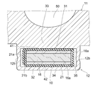
- FIG. 3 shows a cross-sectional view of the heat generating unit 10 accommodated in a certain cylindrical portion 12.
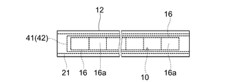
- FIG. 4 corresponds to a plan view of the cylindrical portion 12 viewed from below in FIG.
- the heat generating unit 10 has a PTC (Positive Temperature Coefficient) element 16 as a heat generating element.
- the PTC element 16 is a ceramic element having a positive temperature characteristic, and when the temperature becomes equal to or higher than the Curie point, the resistance rapidly increases and further temperature rise is limited.
- the PTC element 16 is formed in, for example, a rectangular thin plate shape, and electrode surfaces 16a made of metal such as silver or aluminum are formed on both front and back surfaces. A plurality of PTC elements 16 are arranged along the longitudinal direction of the cylindrical portion 12 inside the cylindrical portion 12.
- the electrode plates 41 and 42 are bonded to the pair of electrode surfaces 16a of the PTC element 16, respectively.
- the PTC element 16 is sandwiched between a pair of electrode plates 41 and 42.
- a voltage of opposite polarity is applied to the pair of electrode plates 41 and 42, respectively.
- the electrode plates 41 and 42 are overlapped with the electrode surface 16 a of the PTC element 16 inside the cylindrical portion 12.
- the electrode plates 41 and 42 and the electrode surface 16a are bonded with, for example, a silicone-based adhesive having excellent thermal conductivity.
- the electrode surface 16a is formed on the front and back surfaces of the PTC element 16 by spraying aluminum, for example.
- the electrode surface 16 a is formed by applying, for example, silver paste on the front and back surfaces of the PTC element 16.
- the electrode surface 16a is formed by spraying aluminum. For this reason, fine irregularities are formed on the electrode surface 16a.
- the electrode plates 41 and 42 and the PTC element 16 sandwiched between them are wrapped in an insulating sheet 21.
- the insulating sheet 21 has flexibility, thermal conductivity, and electrical insulation, and is, for example, a polyimide film. Both edge portions 21 a and 21 b of the insulating sheet 21 are overlapped with each other, and the insulating sheet 21 covers the electrode plates 41 and 42 bonded to the PTC element 16.
- the cylinder portion 12 has an inner inner wall 31 provided on the liquid flow path 50 side and an outer inner wall 32 provided on the opposite side.
- the PTC element 16 has one electrode surface 16a facing the inner inner wall 31 side, that is, the liquid flow path 50 side, and the other electrode surface 16a facing the outer inner wall 32 side.
- One electrode plate 41 is interposed between the inner inner wall 31 and one electrode surface 16a, and the other electrode 42 is interposed between the other electrode surface 16a and the outer inner wall 32.
- Both end edges 21 a and 21 b of the insulating sheet 21 are overlapped not on the electrode surface 16 a of the PTC element 16 and the inner inner wall 31 but on the back side of the side surface 12 b of the cylindrical portion 12. Thereby, the fall of the heat transfer efficiency from the PTC element 16 to the liquid flow path 50 can be suppressed.
- the cylindrical portion 12 is formed in a flat shape having an inner inner wall 31 and an outer inner wall 32 facing each other, and a pair of side surfaces 12b that are formed substantially at right angles to them and facing each other.
- the inner inner wall 31 and the outer inner wall 32 are wider and larger in area than the side surface 12b.
- the PTC element 16 and the electrode plates 41 and 42 are accommodated inside the cylindrical portion 12 in a state where the periphery is covered with the insulating sheet 21. Between one electrode surface 16a and the inner inner wall 31, the electrode plate 41 and the insulating sheet 21 are narrowly pressed. Between the other electrode surface 16a and the outer inner wall 32, the electrode plate 42 and the insulating sheet 21 are narrowly pressed.
- the cylindrical portion 12 is crushed by applying mechanical pressure in a direction connecting the inner inner wall 31 and the outer inner wall 32.
- the PTC element 16, the electrode plates 41 and 42, and the insulating sheet 21 are in a state of being compressed between the inner inner wall 31 and the outer inner wall 32, and are fixed in the cylindrical portion 12.
- the side surface 12b of the cylinder part 12 is formed with a groove or a depression along the longitudinal direction, the side surface 12b can be prevented from bulging outward when the cylinder part 12 is crushed.
- sealing bodies 23 having electrical insulation, waterproofness, and heat resistance are provided at the openings at both ends of the cylindrical portion 12.
- a gap between the cylindrical portion 12 and the sealing body 23 is filled with, for example, a silicone-based sealing material having electrical insulation, waterproofness, and heat resistance.
- An electric cable (not shown) is connected to one end of each of the electrode plates 41 and 42, and the electric cable passes through one sealing body 23 and is led out to the outside.
- the electric cable led out to the outside is connected to a power source.
- a portion where the electric cable penetrates the sealing body 23 is filled with, for example, a silicone-based sealing material having electric insulation, waterproofness, and heat resistance.
- the liquid heater 1 according to the present embodiment can be mounted on, for example, an automobile and used as a heater for heating a vehicle. And the electric power from the battery mounted in the motor vehicle is supplied to the PTC element 16 via the electric cable and the electrode plates 41 and 42, and the PTC element 16 generates heat.
- This heat is transmitted to the metal main body 11 through the electrode plates 41 and 42 and the insulating sheet 21 and further to the liquid flowing through the liquid flow path 50.
- a liquid such as water or antifreeze is introduced into the liquid channel 50.
- the liquid flows into the liquid channel 50 from the liquid inlet 21 and flows through the liquid channel 50.
- the liquid flowing through the liquid flow path 50 is heated by heat exchange with the portion 33 between the liquid flow path 50 and the cylindrical portion 12 in the main body 11 heated by the heat generating unit 10, and is heated to the outside from the liquid outlet portion 22 as hot water. leak.
- the main body 11 having the liquid flow path 50 and the cylindrical portion 12 is an integral body formed by, for example, extrusion molding. Therefore, an integral metal is interposed between the inner inner wall 31 and the liquid flow path 50. Further, the heat generating unit 10 is narrowed in the cylindrical portion 12, and the heat generating unit 10 is in close contact with the inner inner wall 31 without interposing an air layer. Therefore, the heat of the heat generating unit 10 can be efficiently transmitted to the liquid flowing through the liquid channel 50.
- the PTC element 16 has a characteristic of releasing energy as it cools. Therefore, the heat of the heat generating unit 10 is efficiently taken from the liquid channel 50 side where the liquid having a lower temperature flows, and as a result, the amount of heat escaping from the outer inner wall 32 side of the cylindrical portion 12 to the opposite side of the liquid channel 50 is It can be suppressed.
- the volume of the portion 33 between the liquid flow path 50 and the inner inner wall 31 is larger than the volume of the outer portion 34 than the outer inner wall 32. For this reason, as represented by an arrow A in FIG. 2, the heat transferred to the portion 34 on the opposite side of the liquid channel 50 in the main body 11 passes through the portion 33 in which the cross-sectional area of the path toward the liquid channel 50 is increased. It can be efficiently transmitted to the liquid flow path 50 through the liquid crystal.
- the present inventors conducted the following experiment using the fluid heater 1 of the embodiment.
- the inlet water temperature of running water was 9.0 ° C
- the environmental temperature was 18 ° C
- the running water amount was 10 liters / minute.
- the electric energy of 3220 W can be converted into the amount of heat of 3220 W, and the efficiency becomes 100%.
- a heat sink is attached to increase the contact area.
- the liquid heater 1 is accommodated in a metal case 60, for example.
- the case 60 may be made of resin.
- the sealing body 23 or the liquid inlet portion 21 and the liquid outlet portion 22 at both ends thereof are both supported by the wall portion of the case 60. That is, both ends of the liquid heater 1 are supported by the case 60, and the main body 11 is in a floating state in the internal space of the case 60. Therefore, the outer surface of the main body 11 does not come into contact with the inner wall of the case 60, and there is a gap between the main body 11 and the inner wall of the case 60.
- the main body 11 since the main body 11 is covered with the case 60, it can prevent that a person and an object touch the surface of the heated main body 11, and can improve safety
- air may be interposed as a heat insulating layer, or a gas having higher heat insulating properties such as CFC gas may be interposed.
- the outer surface of the main body 11 may be covered with, for example, a silicone-based sponge-like heat insulating material 70.
- the case 60 may not be provided.
- the PTC element 16 and the electrode plates 41 and 42 in contact with the PTC element 16 are accommodated inside the cylindrical portion 12 sealed by the sealing body 23 and are not exposed to the outside. Moreover, since the insulating sheet 21 is interposed between the electrode plates 41 and 42 and the inner wall of the cylindrical portion 12, the cylindrical portion 12 is not energized. High safety and reliability can be obtained while obtaining high heat exchange efficiency.
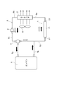
- FIG. 5 is a schematic diagram showing the vehicle-mounted hot water heater system of the embodiment.
- FIG. 5 shows a specific example in which the liquid heater 1 described above is attached to a vehicle such as an automobile.
- the liquid inlet 21 and the liquid outlet 22 are connected to the circulation path 6.
- the circulation path 6 has pipe lines 6a to 6d.
- the pipe 6 a connects the liquid outlet portion 22 and the heater core 2.
- the pipe line 6 b connects the heater core 2 and the hydraulic pump 3.
- the pipe line 6c connects the hydraulic pump 3 and the three-way valve 4.
- the pipe 6 d connects the three-way valve 4 and the liquid inlet 21.
- the circulation path 6 and the liquid heater 1 are also connected to the engine 5 through the pipe lines 7a and 7b.
- the three-way valve 4 blocks the pipe 6c and the pipe 7a and allows the pipe 6c and the pipe 6d to communicate with each other, when the hydraulic pump 3 is driven, the liquid heater 1
- the liquid circulates in the inner and circulation paths 6 in the direction indicated by white arrows in FIG.
- the heat generating unit 10 of the liquid heater 1 by supplying electric power from the battery mounted on the vehicle to the heat generating unit 10 of the liquid heater 1, the heat generating unit 10 generates heat, and the liquid in the liquid flow path 50 is heated.
- the warm water generated by this heating is supplied to the heater core 2 through the liquid outlet portion 22 and the pipe line 6a.
- the hot water supplied to the heater core 2 flows through a pipe provided in the heater core 2. Gas (air) is blown from the blower 8 to the heater core 2. Heat of the hot water flowing through the pipe of the heater core 2 is transmitted to the gas blown from the blower 8 via a heat transfer surface such as a fin provided in the heater core 2. As a result, warm air is blown into the vehicle.
- This mode is selected when the exhaust heat of the engine 5 cannot be used, for example, when the engine 5 is started.
- the three-way valve 4 is switched so that the pipe line 6c and the pipe line 7a communicate with each other, and the pipe line 6c and the pipe line 6d are shut off. Function as.
- the flow of the liquid at this time is represented by a black arrow in FIG.
- Hot water that has passed through the engine 5 and has been heated by heat exchange with the engine 5 is supplied to the heater core 2 via the pipe lines 7b and 6d, the inflow part 51, the liquid flow path 50, the liquid outlet part 22 and the pipe line 6a. . Therefore, in this mode, hot water can be supplied to the heater core 2 without energizing (generating heat) the heat generating unit 10, and by driving the blower 8, hot air can be sent into the vehicle.
- the contact area between the inner wall and the liquid can be increased, and the heat exchange efficiency can be further increased.
- FIG. 6A shows a liquid flow channel 51 in which star-shaped irregularities are formed on the inner wall.
- FIG. 6B shows a liquid channel 52 in which corrugated irregularities are formed on the inner wall.
- a partition 54 may be provided in the liquid channel 53 to increase the contact area with the liquid.
- a partition is not restricted to the form shown in FIG.6 (c), For example, you may partition a liquid flow path in a grid
- cylindrical portion 12 is not limited to a rectangular cylindrical flat shape, and may be an ellipse or a circular shape. As the distance between the PTC element 16 and the inner inner wall 31 is shorter, the efficiency of heat transfer to the portion 33 of the main body 11 can be increased.
- the liquid heater 1 of the embodiment can be widely applied to uses other than in-vehicle, and in any application, the liquid can be efficiently heated to generate hot water with a small, simple and low-cost configuration.
- SYMBOLS 1 Liquid heater, 10 ... Heat generating unit, 11 ... Main body, 12 ... Tube part, 16 ... PTC element, 16a ... Electrode surface, 21 ... Insulating sheet, 31 ... Inner inner wall, 32 ... Outer inner wall, 41 ... Electrode plate, 50 to 53 ... Liquid flow path
Landscapes
- Engineering & Computer Science (AREA)
- Physics & Mathematics (AREA)
- Thermal Sciences (AREA)
- Mechanical Engineering (AREA)
- Chemical & Material Sciences (AREA)
- Combustion & Propulsion (AREA)
- General Engineering & Computer Science (AREA)
- Air-Conditioning For Vehicles (AREA)
- Resistance Heating (AREA)
Abstract
L'invention concerne un dispositif de chauffage de liquide qui est équipé : d'un corps principal en métal qui possède un trajet d'écoulement de liquide dans lequel un liquide s'écoule, et une partie conduite dans laquelle est logée une unité de génération de chaleur agencée d'un seul tenant côté extérieur du trajet d'écoulement de liquide; et d'un corps de scellement qui obture la partie extrémité de la partie conduite. L'unité de génération de chaleur possède : un élément de coefficient positif de température possédant une face d'électrode; une plaque d'électrode mise en adhésion sur la face d'électrode; et un corps isolant agencé entre la plaque d'électrode et la paroi interne de la partie conduite, et se superposant à la plaque d'électrode. L'unité de génération de chaleur est pincée entre les parois internes de la partie conduite, il n'y a pas d'intervalle entre le trajet d'écoulement de liquide et l'unité de génération de chaleur, et une partie du corps principal s'intercale d'un seul tenant.
Priority Applications (2)
| Application Number | Priority Date | Filing Date | Title |
|---|---|---|---|
| PCT/JP2011/073121 WO2012120718A1 (fr) | 2011-03-04 | 2011-10-06 | Dispositif de chauffage, et système de pompe à chaleur |
| JP2013503329A JP6106078B2 (ja) | 2011-03-04 | 2011-10-06 | ヒータ及びヒートポンプシステム |
Applications Claiming Priority (2)
| Application Number | Priority Date | Filing Date | Title |
|---|---|---|---|
| JP2011048354 | 2011-03-04 | ||
| JP2011-048354 | 2011-03-04 |
Publications (1)
| Publication Number | Publication Date |
|---|---|
| WO2012120708A1 true WO2012120708A1 (fr) | 2012-09-13 |
Family
ID=46797696
Family Applications (2)
| Application Number | Title | Priority Date | Filing Date |
|---|---|---|---|
| PCT/JP2011/069176 Ceased WO2012120708A1 (fr) | 2011-03-04 | 2011-08-25 | Dispositif de chauffage de liquide |
| PCT/JP2011/073121 Ceased WO2012120718A1 (fr) | 2011-03-04 | 2011-10-06 | Dispositif de chauffage, et système de pompe à chaleur |
Family Applications After (1)
| Application Number | Title | Priority Date | Filing Date |
|---|---|---|---|
| PCT/JP2011/073121 Ceased WO2012120718A1 (fr) | 2011-03-04 | 2011-10-06 | Dispositif de chauffage, et système de pompe à chaleur |
Country Status (2)
| Country | Link |
|---|---|
| JP (1) | JP6106078B2 (fr) |
| WO (2) | WO2012120708A1 (fr) |
Cited By (6)
| Publication number | Priority date | Publication date | Assignee | Title |
|---|---|---|---|---|
| WO2015184859A1 (fr) * | 2014-06-03 | 2015-12-10 | 上海帕克热敏陶瓷有限公司 | Élément chauffant de liquide ctp de type à chauffage instantané |
| CN105444401A (zh) * | 2015-12-08 | 2016-03-30 | 芜湖恒美电热器具有限公司 | Ptc液体加热器 |
| CN108870505A (zh) * | 2018-08-24 | 2018-11-23 | 佛山市南海区鑫之诚电子制造厂 | 一种水地暖加热器结构 |
| CN109599641A (zh) * | 2017-09-30 | 2019-04-09 | 比亚迪股份有限公司 | 换热管以及电池热管理系统和车辆 |
| US11428455B2 (en) * | 2017-05-25 | 2022-08-30 | Lg Electronics Inc. | Defrosting apparatus and refrigerator comprising same |
| JP2023045947A (ja) * | 2021-09-22 | 2023-04-03 | カシン工業株式会社 | ヒータケース、ヒータ装置および車載用ヒータユニット |
Families Citing this family (5)
| Publication number | Priority date | Publication date | Assignee | Title |
|---|---|---|---|---|
| CN103743093B (zh) * | 2014-01-02 | 2016-02-17 | 常熟市林芝电热器件有限公司 | Ptc液体加热器 |
| KR102367211B1 (ko) * | 2015-10-27 | 2022-02-24 | 한온시스템 주식회사 | 냉각수 순환 펌프 |
| WO2017030382A1 (fr) * | 2015-08-18 | 2017-02-23 | 한온시스템 주식회사 | Dispositif de chauffage de véhicule, et pompe de circulation d'eau de refroidissement située à l'intérieur de ce dernier |
| CN105091318A (zh) * | 2015-09-08 | 2015-11-25 | 常熟市林芝电热器件有限公司 | 具有喷嘴防堵塞功能的ptc液体加热器 |
| CN106641729A (zh) * | 2017-02-16 | 2017-05-10 | 中国石油大学(华东) | 一种井口管道半导体加热器 |
Citations (3)
| Publication number | Priority date | Publication date | Assignee | Title |
|---|---|---|---|---|
| JPS58124727U (ja) * | 1982-02-17 | 1983-08-25 | 千々波 天信 | 流体加熱器 |
| JPS5941988U (ja) * | 1982-09-10 | 1984-03-17 | 株式会社村田製作所 | パイプ加熱装置 |
| JPH04117343U (ja) * | 1991-03-26 | 1992-10-21 | 京セラ株式会社 | 流体加熱装置 |
Family Cites Families (5)
| Publication number | Priority date | Publication date | Assignee | Title |
|---|---|---|---|---|
| JPS5275144U (fr) * | 1975-12-03 | 1977-06-04 | ||
| JPS6345755Y2 (fr) * | 1980-01-18 | 1988-11-28 | ||
| JPH116651A (ja) * | 1997-06-13 | 1999-01-12 | Janome Sewing Mach Co Ltd | 流水加熱装置 |
| JP2001210765A (ja) * | 2000-01-27 | 2001-08-03 | Toyo Radiator Co Ltd | 排ガス用ヒートシンクおよびその製造方法 |
| JP2007255736A (ja) * | 2006-03-20 | 2007-10-04 | Daikin Ind Ltd | 冷媒加熱装置および加熱制御方法 |
-
2011
- 2011-08-25 WO PCT/JP2011/069176 patent/WO2012120708A1/fr not_active Ceased
- 2011-10-06 WO PCT/JP2011/073121 patent/WO2012120718A1/fr not_active Ceased
- 2011-10-06 JP JP2013503329A patent/JP6106078B2/ja active Active
Patent Citations (3)
| Publication number | Priority date | Publication date | Assignee | Title |
|---|---|---|---|---|
| JPS58124727U (ja) * | 1982-02-17 | 1983-08-25 | 千々波 天信 | 流体加熱器 |
| JPS5941988U (ja) * | 1982-09-10 | 1984-03-17 | 株式会社村田製作所 | パイプ加熱装置 |
| JPH04117343U (ja) * | 1991-03-26 | 1992-10-21 | 京セラ株式会社 | 流体加熱装置 |
Cited By (8)
| Publication number | Priority date | Publication date | Assignee | Title |
|---|---|---|---|---|
| WO2015184859A1 (fr) * | 2014-06-03 | 2015-12-10 | 上海帕克热敏陶瓷有限公司 | Élément chauffant de liquide ctp de type à chauffage instantané |
| CN105318551A (zh) * | 2014-06-03 | 2016-02-10 | 上海帕克热敏陶瓷有限公司 | 一种新型即热式ptc液体加热器 |
| CN105444401A (zh) * | 2015-12-08 | 2016-03-30 | 芜湖恒美电热器具有限公司 | Ptc液体加热器 |
| US11428455B2 (en) * | 2017-05-25 | 2022-08-30 | Lg Electronics Inc. | Defrosting apparatus and refrigerator comprising same |
| CN109599641A (zh) * | 2017-09-30 | 2019-04-09 | 比亚迪股份有限公司 | 换热管以及电池热管理系统和车辆 |
| CN108870505A (zh) * | 2018-08-24 | 2018-11-23 | 佛山市南海区鑫之诚电子制造厂 | 一种水地暖加热器结构 |
| JP2023045947A (ja) * | 2021-09-22 | 2023-04-03 | カシン工業株式会社 | ヒータケース、ヒータ装置および車載用ヒータユニット |
| JP7786710B2 (ja) | 2021-09-22 | 2025-12-16 | カシン工業株式会社 | ヒータケース、ヒータ装置および車載用ヒータユニット |
Also Published As
| Publication number | Publication date |
|---|---|
| WO2012120718A1 (fr) | 2012-09-13 |
| JPWO2012120718A1 (ja) | 2014-07-07 |
| JP6106078B2 (ja) | 2017-03-29 |
Similar Documents
| Publication | Publication Date | Title |
|---|---|---|
| JP6106078B2 (ja) | ヒータ及びヒートポンプシステム | |
| WO2012011198A1 (fr) | Appareil de chauffage monté sur un véhicule, à production d'eau chaude, hautement efficace doté d'une voie de passage de liquide intérieure | |
| CN104144806B (zh) | 冷却水加热式加热器 | |
| US9863663B2 (en) | Heat exchanger | |
| KR101764598B1 (ko) | 냉각수 히터 | |
| CN103517467B (zh) | 一种ptc电热元件、电加热装置以及电动车 | |
| CN104144530B (zh) | 一种电制热器及其制备方法 | |
| KR20100055262A (ko) | 고용량 피티씨 히터 | |
| CN108738177B (zh) | 电加热装置 | |
| CN108351127B (zh) | 用于电池的温度控制的热交换器、尤其是热电热泵 | |
| JP2010135717A (ja) | Ptcロード組立体及びこれを用いた車両用ptcヒーター | |
| JP6627058B2 (ja) | 高耐電圧絶縁防水型車載用ヒータおよび車載用ヒータユニット | |
| KR102148527B1 (ko) | 온도 퓨즈에 대한 단열 차폐 구조를 갖는 배터리용 냉각수 가열 장치 | |
| CN103228998A (zh) | 车辆电加热装置 | |
| CN107950074A (zh) | 车辆辐射加热器 | |
| JP2011088506A (ja) | 車載温水生成ユニット | |
| KR102014085B1 (ko) | 나노카본발열체를 이용한 쿨런트 히터 | |
| JP4264008B2 (ja) | 電気発熱装置を有する暖房目的に役立つ熱交換器 | |
| KR102262143B1 (ko) | 차량용 복사열 히터 | |
| KR102274247B1 (ko) | 발열체 및 이를 포함하는 히터유닛 | |
| CN205510443U (zh) | 一种翅型ptc加热装置 | |
| KR100831832B1 (ko) | 피티씨 로드 조립체 | |
| JP2010276264A (ja) | 温水生成ユニット、車載温水ヒータシステム及び温水生成ユニットの組立方法 | |
| KR200349121Y1 (ko) | 냉각수 가열 방식의 히터장치 | |
| CN215321888U (zh) | 电动车辆及其电加热设备 |
Legal Events
| Date | Code | Title | Description |
|---|---|---|---|
| 121 | Ep: the epo has been informed by wipo that ep was designated in this application |
Ref document number: 11860481 Country of ref document: EP Kind code of ref document: A1 |
|
| NENP | Non-entry into the national phase |
Ref country code: DE |
|
| 122 | Ep: pct application non-entry in european phase |
Ref document number: 11860481 Country of ref document: EP Kind code of ref document: A1 |
|
| NENP | Non-entry into the national phase |
Ref country code: JP |