WO2012120969A1 - Bouchon destiné à un tuyau conducteur de chaleur, dispositif permettant de fixer un bouchon destiné à un tuyau conducteur de chaleur, et procédé d'obturation d'un tuyau conducteur de chaleur - Google Patents
Bouchon destiné à un tuyau conducteur de chaleur, dispositif permettant de fixer un bouchon destiné à un tuyau conducteur de chaleur, et procédé d'obturation d'un tuyau conducteur de chaleur Download PDFInfo
- Publication number
- WO2012120969A1 WO2012120969A1 PCT/JP2012/053115 JP2012053115W WO2012120969A1 WO 2012120969 A1 WO2012120969 A1 WO 2012120969A1 JP 2012053115 W JP2012053115 W JP 2012053115W WO 2012120969 A1 WO2012120969 A1 WO 2012120969A1
- Authority
- WO
- WIPO (PCT)
- Prior art keywords
- plug
- heat transfer
- transfer tube
- wedge member
- plug body
- Prior art date
- Legal status (The legal status is an assumption and is not a legal conclusion. Google has not performed a legal analysis and makes no representation as to the accuracy of the status listed.)
- Ceased
Links
Images


Classifications
-
- B—PERFORMING OPERATIONS; TRANSPORTING
- B65—CONVEYING; PACKING; STORING; HANDLING THIN OR FILAMENTARY MATERIAL
- B65D—CONTAINERS FOR STORAGE OR TRANSPORT OF ARTICLES OR MATERIALS, e.g. BAGS, BARRELS, BOTTLES, BOXES, CANS, CARTONS, CRATES, DRUMS, JARS, TANKS, HOPPERS, FORWARDING CONTAINERS; ACCESSORIES, CLOSURES, OR FITTINGS THEREFOR; PACKAGING ELEMENTS; PACKAGES
- B65D59/00—Plugs, sleeves, caps, or like rigid or semi-rigid elements for protecting parts of articles or for bundling articles, e.g. protectors for screw-threads, end caps for tubes or for bundling rod-shaped articles
- B65D59/02—Plugs
-
- F—MECHANICAL ENGINEERING; LIGHTING; HEATING; WEAPONS; BLASTING
- F16—ENGINEERING ELEMENTS AND UNITS; GENERAL MEASURES FOR PRODUCING AND MAINTAINING EFFECTIVE FUNCTIONING OF MACHINES OR INSTALLATIONS; THERMAL INSULATION IN GENERAL
- F16L—PIPES; JOINTS OR FITTINGS FOR PIPES; SUPPORTS FOR PIPES, CABLES OR PROTECTIVE TUBING; MEANS FOR THERMAL INSULATION IN GENERAL
- F16L55/00—Devices or appurtenances for use in, or in connection with, pipes or pipe systems
- F16L55/10—Means for stopping flow in pipes or hoses
- F16L55/12—Means for stopping flow in pipes or hoses by introducing into the pipe a member expandable in situ
- F16L55/128—Means for stopping flow in pipes or hoses by introducing into the pipe a member expandable in situ introduced axially into the pipe or hose
- F16L55/136—Means for stopping flow in pipes or hoses by introducing into the pipe a member expandable in situ introduced axially into the pipe or hose the closure device being a plug fixed by radially expanding or deforming a split ring, hooks or the like
-
- F—MECHANICAL ENGINEERING; LIGHTING; HEATING; WEAPONS; BLASTING
- F28—HEAT EXCHANGE IN GENERAL
- F28F—DETAILS OF HEAT-EXCHANGE AND HEAT-TRANSFER APPARATUS, OF GENERAL APPLICATION
- F28F11/00—Arrangements for sealing leaky tubes and conduits
- F28F11/02—Arrangements for sealing leaky tubes and conduits using obturating elements, e.g. washers, inserted and operated independently of each other
-
- Y—GENERAL TAGGING OF NEW TECHNOLOGICAL DEVELOPMENTS; GENERAL TAGGING OF CROSS-SECTIONAL TECHNOLOGIES SPANNING OVER SEVERAL SECTIONS OF THE IPC; TECHNICAL SUBJECTS COVERED BY FORMER USPC CROSS-REFERENCE ART COLLECTIONS [XRACs] AND DIGESTS
- Y10—TECHNICAL SUBJECTS COVERED BY FORMER USPC
- Y10T—TECHNICAL SUBJECTS COVERED BY FORMER US CLASSIFICATION
- Y10T29/00—Metal working
- Y10T29/49—Method of mechanical manufacture
- Y10T29/49826—Assembling or joining
Definitions
- the present invention provides a heat transfer tube plug plug for plugging and closing the heat transfer tube as a heat transfer tube repair, a heat transfer tube plug plug mounting device for mounting the heat transfer tube plug plug on the heat transfer tube, and the The present invention relates to a heat transfer tube plugging method for mounting a heat transfer tube plug on a heat transfer tube and plugging the heat transfer tube.
- a steam generator used in a pressurized water reactor has radioactive water from the primary side when the side wall of a U-shaped heat transfer tube contained in the reactor deteriorates beyond the allowable limit. May leak and be mixed into non-radioactive water on the secondary side. For this reason, it is known that the possibility of the above-mentioned mixing is prevented by closing the end portion of the heat transfer tube which may be deteriorated or deteriorated.
- a tube plugging device described in Patent Document 1 is built in a tubular plug shell having an open end opened at one end and a closed end closed at the other end, and the plug shell.
- An expander element movably provided between the closed end and the open end, and to facilitate movement of the expander element by introducing pressurized hydraulic fluid into the plug shell
- expansion means having a supply source of pressurized hydraulic oil.
- the tube plugging method described in Patent Document 1 uses the plugging device described above, introduces pressurized hydraulic oil into the plug shell, expands the plug shell in the radial direction, and Facilitates movement of the expander element between the closed and open ends of the plug shell.
- the hollow interior of the plug shell is surrounded by a tapered inner wall surface.
- the inner wall surface has a circular cross section in the transverse direction with respect to the longitudinal axis of the plug shell. Further, the inner wall surface converges so that the open end side of the plug shell has a minimum area, and widens so that the closed end side of the plug shell has a maximum area.
- the expander element is formed of a cork-like conical body, and the conical taper is formed substantially equal to the taper of the inner wall surface of the plug shell.
- the apparatus of Patent Document 1 converges so that the taper of the inner wall surface of the plug shell becomes a minimum area on the open end side, and the taper of the expander element is substantially equal to the inner wall surface taper of the plug shell. So that the expander element must be built in the plug shell. Specifically, the open end portion side of the plug shell is expanded and molded so that at least the large-diameter portion of the expander element passes. Then, in a state where the expander element is arranged in the plug shell, the open end side of the plug shell is drawn so as to have a minimum area. This drawing process is not easy and requires high technology and time.
- the expander element is always built in the plug shell, it is difficult to inspect the minimum thickness portion of the plug shell after completion.
- this device is important to plug the end of the heat transfer tube that may be deteriorated or deteriorated. It is important to inspect the thickness of the plug shell before use to ensure the integrity of the plug shell.
- the present invention solves the above-described problems, makes it easy to manufacture and process, and can easily perform a pre-use inspection for maintaining the plugging function, and a heat transfer tube plugging method. It is an object of the present invention to provide a heat transfer tube plug plug mounting device in which the heat transfer tube plug plug can be easily installed on the heat transfer tube.
- the heat transfer tube plug of the present invention is a heat transfer tube plug for plugging and closing the heat transfer tube, and is formed so as to be insertable into the heat transfer tube.
- a plug body formed by closing one end and opening the other end of the tubular body, and formed so as to be insertable / removable into the plug body from the tubular open side of the plug body, and inserted into the plug body.
- a columnar member having a tapered surface on the outer periphery, the outer diameter of which gradually decreases toward the open side of the plug body in an open state, and is formed so as to be insertable / removable into the plug body from the cylindrical open side of the plug body,
- a wedge member having an inner diameter with a tapered surface facing the tapered surface of the columnar member, the inner diameter gradually decreasing toward the open side of the plug body in a state of being inserted into the plug body.
- the columnar member and the wedge member are inserted into the plug main body so that the taper surfaces thereof face each other, and the columnar member is moved to the open side of the plug main body, whereby the taper of the columnar member is obtained.
- the surface is in sliding contact with the tapered surface of the wedge member, and the diameter of the wedge member is increased, whereby the diameter of the plug body is increased and comes into contact with the inner peripheral surface of the heat transfer tube.
- the heat transfer tube is plugged and plugged by the plug body. Since the plug member for heat transfer tubes is formed so that the columnar member and the wedge member can be inserted into and removed from the plug body, the plug body, the columnar member and the wedge member can be processed separately. . Therefore, special processing such as conventional drawing processing is unnecessary, and manufacturing processing can be easily performed. In addition, since the plug body, the columnar member, and the wedge member can be separately provided, it is possible to easily perform an inspection before use for maintaining the plugging function of the plug body.
- the plug for a heat transfer tube is the wedge member in a state where the columnar member is inserted into the plug main body and the taper surfaces of the columnar member and the wedge member face each other. It is characterized by having a plurality of ridges that are continuous in the circumferential direction and arranged in parallel in the longitudinal direction with respect to the outer periphery of the plug main body at the portion where is disposed.
- the position of the wedge member is determined in the positional relationship in which the columnar member is inserted into the plug body and the tapered surfaces of the columnar member and the wedge member face each other. From this, it is possible to specify the portion that contacts the inner peripheral surface of the heat transfer tube by the expansion of the plug main body accompanying the expansion of the wedge member. For this reason, by providing a protrusion on the outer periphery of the plug main body at the portion where the wedge member is disposed, it is possible to appropriately provide a protrusion at a position where the heat transfer tube is blocked, and the heat transfer tube is reliably blocked. Can do.
- the plug for a heat transfer tube of the present invention is characterized in that the wedge member is formed to be hard with respect to the plug body and is formed to be soft with respect to the columnar member.
- the wedge member can be easily expanded in diameter by the movement of the columnar member, and the plug main body can be maintained in an expanded shape by the expanded wedge member.
- the heat transfer tube plug plug mounting device of the present invention is a heat transfer tube plug plug mounting device that mounts the heat transfer tube plug plug according to any one of the above on a heat transfer tube.
- a rod-shaped member having a tip inserted from the open side of the plug main body is fitted into the columnar member, and the rod-shaped member is inserted therein, and the tip inserted from the open side of the plug main body is A contact member that contacts the end portion of the wedge member, and a moving unit that moves the rod-shaped member in a manner of being pulled out from the open side of the plug body.
- the columnar member fitted to the rod-shaped member is moved by the moving means, and the movement of the wedge member accompanying the movement of the columnar member is regulated by the contact member.
- the plug for heat transfer tubes can be easily installed on the heat transfer tubes.
- the abutting member is in a state where the tapered surfaces of the columnar member and the wedge member face each other, the tip abuts against the end of the wedge member, And a base end contacts the opening edge of the said plug main body, It is characterized by the above-mentioned.
- the wedge member accompanying the movement of the columnar member by the contact member while positioning the plug body in the heat transfer tube with the heat transfer tube plug plug inserted into the heat transfer tube Regulate the movement of Thereby, the plug for heat transfer tubes can be easily installed at a desired position of the heat transfer tubes.
- the heat transfer tube plugging method of the present invention is a heat transfer tube plugging method in which the heat transfer tube plug plug according to any one of the above is mounted on a heat transfer tube and the heat transfer tube is plugged.
- the method includes a step of inserting the plug body into the heat transfer tube, and a step of moving the columnar member to the open side of the plug body.
- the columnar member and the wedge member are inserted into the plug main body so that the tapered surfaces thereof face each other, and the columnar member is moved to the open side of the plug main body, whereby the tapered surface of the columnar member is However, it comes into sliding contact with the tapered surface of the wedge member, and the diameter of the wedge member is increased, whereby the diameter of the plug body is increased and comes into contact with the inner peripheral surface of the heat transfer tube.
- the heat transfer tube plug can be easily installed on the heat transfer tube.
- the plug main body, the columnar member, and the wedge member can be processed separately by setting them separately. Therefore, special processing such as conventional drawing processing is unnecessary, and manufacturing processing can be easily performed.
- the plug body, the columnar member, and the wedge member can be separately provided, it is possible to easily perform an inspection before use for maintaining the plugging function of the plug body.
- FIG. 1 is a schematic side sectional view of a steam generator according to an embodiment of the present invention.
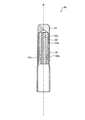
- FIG. 2 is an exploded side sectional view of the heat transfer tube plug according to Embodiment 1 of the present invention.
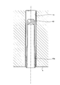
- FIG. 3 is a side cross-sectional view of a state where the heat transfer tube plug plug according to Embodiment 1 of the present invention is assembled.
- FIG. 4 is a side cross-sectional view of the heat transfer tube plug plug mounting device according to Embodiment 1 of the present invention.
- FIG. 5 is a side sectional view showing the heat transfer tube plugging method according to Embodiment 1 of the present invention.
- FIG. 6 is a side sectional view showing the heat transfer tube plugging method according to Embodiment 1 of the present invention.
- FIG. 1 is a schematic side sectional view of a steam generator according to an embodiment of the present invention.
- FIG. 2 is an exploded side sectional view of the heat transfer tube plug according to Embodiment 1 of the present invention.
- FIG. 7 is a side sectional view showing the heat transfer tube plugging method according to Embodiment 1 of the present invention.
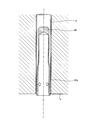
- FIG. 8 is an exploded side cross-sectional view of the heat transfer tube plug according to Embodiment 2 of the present invention.
- FIG. 9 is a side sectional view showing a heat transfer tube plugging method according to Embodiment 2 of the present invention.
- FIG. 1 is a schematic side sectional view of a steam generator according to the present embodiment.
- the steam generator 1 is used, for example, in a pressurized water reactor (PWR: Pressurized Water Reactor).
- the pressurized water reactor uses light water as a reactor coolant and neutron moderator.
- the pressurized water reactor sends primary cooling water to the steam generator 1 as high-temperature and high-pressure water that does not boil light water over the entire core.
- the heat of the primary cooling water at high temperature and high pressure is transmitted to the secondary cooling water, and water vapor is generated in the secondary cooling water. Then, the steam generator is rotated by this steam to generate electricity.
- the steam generator 1 has a hollow cylindrical shape that extends in the vertical direction and is hermetically sealed, and has a body portion 2 in which the lower half is slightly smaller in diameter than the upper half.
- the trunk portion 2 is provided with a tube group outer cylinder 3 having a cylindrical shape disposed at a predetermined distance from the inner wall surface of the trunk portion 2 in the lower half portion thereof.
- the lower end portion of the tube group outer tube 3 extends to the vicinity of the tube plate 4 disposed below in the lower half of the body portion 2.
- a heat transfer tube group 5A is provided in the tube group outer tube 3.
- the heat transfer tube group 5A includes a plurality of heat transfer tubes 5 having an inverted U shape.
- Each heat transfer tube 5 is arranged with the U-shaped arc portion facing upward, the lower end portion is inserted and fixed in the tube hole 4 a of the tube plate 4, and the intermediate portion is interposed through a plurality of tube support plates 6. It is supported by the tube group outer tube 3.
- a large number of heat transfer tube insertion holes are formed in the tube support plate 6, and each heat transfer tube 5 is inserted into the heat transfer tube insertion hole to support each heat transfer tube 5.
- the body 2 is provided with a water chamber 7 at its lower end.
- the interior of the water chamber 7 is divided into an entrance chamber 7A and an exit chamber 7B by a partition wall 8.
- One end of each heat transfer tube 5 communicates with the entrance chamber 7A, and the other end of each heat transfer tube 5 communicates with the exit chamber 7B.
- the entrance chamber 7A is formed with an inlet nozzle 7Aa that communicates with the outside of the body portion 2
- the exit chamber 7B is formed with an exit nozzle 7Ba that communicates with the outside of the body portion 2.
- the inlet nozzle 7Aa is connected to a cooling water pipe (not shown) through which primary cooling water is sent from the pressurized water reactor, and the outlet nozzle 7Ba sends the primary cooling water after heat exchange to the pressurized water reactor.
- the cooling water piping (not shown) to send is connected.
- an air-water separator 9 that separates feed water into steam and hot water, and a moisture separator that removes the moisture of the separated steam and makes it close to dry steam. 10 is provided.
- a water supply pipe 11 for supplying secondary cooling water from the outside into the body 2 is inserted.
- drum 2 has the vapor
- the body 2 has a tube plate in the lower half of which the secondary cooling water supplied from the water supply pipe 11 into the body 2 flows down between the body 2 and the tube group outer tube 3. 4, a water supply passage 13 is formed that is folded back and raised along the heat transfer tube group 5A.
- the steam outlet 12 is connected to a cooling water pipe (not shown) for sending steam to the turbine, and the water supply pipe 11 has two steams used in the turbine cooled by a condenser (not shown).
- a cooling water pipe (not shown) for supplying the next cooling water is connected.
- the primary cooling water heated in the pressurized water reactor is sent to the entrance chamber 7A, circulates through the numerous heat transfer tubes 5, and reaches the exit chamber 7B.
- the secondary cooling water cooled by the condenser is sent to the water supply pipe 11 and rises along the heat transfer pipe group 5 ⁇ / b> A through the water supply path 13 in the trunk portion 2. At this time, heat exchange is performed between the high-pressure and high-temperature primary cooling water and the secondary cooling water in the trunk portion 2. Then, the cooled primary cooling water is returned from the exit chamber 7B to the pressurized water reactor.
- the secondary cooling water subjected to heat exchange with the high-pressure and high-temperature primary cooling water rises in the body portion 2 and is separated into steam and hot water by the steam separator 9.
- the separated steam is sent to the turbine after moisture is removed by the moisture separator 10.
- FIG. 2 is an exploded side sectional view of the heat transfer tube plug according to the present embodiment
- FIG. 3 is a side cross sectional view of the heat transfer tube plug according to the present embodiment assembled.
- the heat transfer tube plug 20 has a plug body 21, a columnar member 22, and a wedge member 23.
- the plug main body 21 is formed in a cylindrical shape and has an outer diameter smaller than the inner diameter of the heat transfer tube 5 so that the plug body 21 can be inserted into the heat transfer tube 5 that is opened and provided on the water chamber 7 side of the tube plate 4. Is formed. Further, the plug main body 21 is formed by closing one end of the cylindrical shape that is the front end side inserted into the heat transfer tube 5 and opening the other end of the cylindrical shape that is the rear end side. Further, as shown in FIG. 2, the plug body 21 has a columnar member 22 to be described later inserted into a closed portion of the plug body 21, and the taper surfaces 22a and 23a between the columnar member 22 and a wedge member 23 to be described later.
- the outer periphery of the portion where the wedge member 23 is disposed has a plurality of ridges 21a that are continuous in the circumferential direction and arranged in parallel in the longitudinal direction (four in the present embodiment).
- the plug body 21 is formed of a super heat resistant material (for example, Inconel (registered trademark)) so that it can be used in the steam generator 1 in use.
- the columnar member 22 is formed in a columnar shape, and has an outer diameter smaller than the inner diameter of the plug body 21 so that it can be inserted into and removed from the cylindrical body of the plug body 21.
- the columnar member 22 has a tapered surface 22a on the outer periphery that gradually decreases in outer diameter from one end side to the other end side. The columnar member 22 is inserted into the plug body 21 from one end side so that the outer diameter of the tapered surface 22a gradually decreases toward the open side of the plug body 21 in a state where the columnar member 22 is inserted into the plug body 21.
- the columnar member 22 is movable in the cylindrical longitudinal direction of the plug main body 21 (the extending direction of the axis R) so as to come out of the plug main body 21 while being inserted into the plug main body 21 alone. Is provided. Further, the columnar member 22 has a female screw hole 22b formed in the extending direction of the axis R which is the longitudinal direction thereof. The female screw hole 22 b is provided so as to penetrate in the extending direction of the axis R of the columnar member 22.
- This columnar member 22 is formed of a corrosion-resistant material (for example, a stainless alloy) so that it can be used in the steam generator 1 in use.
- the wedge member 23 is formed in a cylindrical shape and has an outer diameter smaller than the inner diameter of the plug body 21 so that the wedge member 23 can be inserted into and removed from the plug body 21 from the cylindrical open side of the plug body 21.
- the wedge member 23 has a tapered surface 23a on the inner periphery that gradually decreases in inner diameter from one end side toward the other end side. The wedge member 23 is inserted into the plug body 21 from one end side so that the inner diameter gradually decreases toward the opening side of the plug body 21 while the wedge member 23 is inserted into the plug body 21.
- the wedge member 23 has an inner diameter larger than the outer diameter on the other end side of the columnar member 22 so that the other end side (small outer diameter side) of the columnar member 22 is inserted from one end side (large inner diameter side) thereof. One end side is formed. Further, the wedge member 23 has an inner diameter smaller than the outer diameter on one end side of the columnar member 22 and the other end so that the one end side (large outer diameter side) of the columnar member 22 does not come off from the other end side (small inner diameter side). The side is formed. As described above, the wedge member 23 is inserted at the other end side (small outer diameter side) of the columnar member 22 from one end side (large inner diameter side), but from the other end side (small inner diameter side) of the columnar member 22.
- the one end side does not come off, and the tapered surfaces 22a and 23a face each other with the columnar member 22 inserted.
- the outer periphery of the wedge member 23 is formed with the same diameter from one end side to the other end side.
- the wedge member 23 is formed to be hard with respect to the plug body 21 by making the plug body 21 thin, and is formed of a soft material (for example, Inconel (registered trademark)) with respect to the columnar member 22. Yes.
- the wedge member 23 may be provided with a slit in the longitudinal direction of the wedge member 23 in order to easily expand the diameter of the wedge member 23 by the movement of the columnar member 22.
- FIG. 4 is a side cross-sectional view of the heat transfer tube plug mounting device according to the present embodiment.
- FIG. 4 the form which attached the plug plug 20 for heat exchanger tubes to the plug plug attachment apparatus 30 for heat exchanger tubes is shown.
- the heat transfer tube plug plug attachment device 30 includes a rod-shaped member 31, a contact member 32, and a moving means 33.
- the rod-shaped member 31 is formed as a long rod-shaped body, and is configured so that the tip portion thereof is fitted to the columnar member 22. Specifically, the rod-shaped member 31 is formed with a male screw portion 31a that is screwed into a female screw hole 22b formed in the columnar member 22 at a tip portion thereof. Further, the length of the male screw portion 31 a is substantially the same as the length of the female screw hole 22 b penetrating in the extending direction of the axis R of the columnar member 22. Further, the rod-like member 31 is formed with an outer diameter that is larger on the base end side than the diameter of the male screw portion 31a.
- the abutting member 32 constitutes the main body of the heat transfer tube plug plug attachment device 30, and the proximal end side of the rod-shaped member 31 is inserted into the interior, and the rod-shaped member 31 is supported so as to be movable in the longitudinal direction.
- the abutting member 32 is formed in a cylindrical shape at a distal end portion 32a through which the rod-shaped member 31 is inserted, and can be inserted into and removed from the plug main body 21 from the cylindrical open side of the plug main body 21.
- the outer diameter is smaller than the inner diameter of 21.
- the distal end portion 32 a of the rod-shaped member 31 is in contact with the other end of the wedge member 23, thereby restricting the movement of the wedge member 23 to the other end side.
- the base end portion 32 b that passes through the rod-shaped member 31 is formed with an outer diameter larger than the outer diameter of the distal end portion 32 a, and is a flat surface that comes into contact with the opening edge that is the cylindrical open side of the plug body 21.
- An abutment surface 32c is formed.
- the moving means 33 is provided at the base end portion 32b of the abutting member 32, is connected to the rod-shaped member 31, and moves the rod-shaped member 31 in a direction of being pulled out from the cylindrical open side of the plug body 21.
- actuators such as a hydraulic cylinder, a pneumatic cylinder, a hydraulic motor, and a servo motor.
- 5 to 7 are side sectional views showing the heat transfer tube plugging method according to the present embodiment.
- the heat transfer tube plugging method of the present embodiment uses the heat transfer tube plug plug mounting device 30 described above, and plugs and closes the heat transfer tube 5 with the heat transfer tube plug plug 20 described above.
- the male screw portion 31a of the rod-shaped member 31 protruding from the tip of the tip end portion 32a of the contact member 32 is It is inserted into the wedge member 23 of the heat transfer tube plug plug 20.
- the rod-shaped member 31 is inserted from the other end side of the wedge member 23 so that one end side of the wedge member 23 having a large inner diameter becomes the tip side of the rod-shaped member 31.
- the rod-shaped member 31 of the heat transfer tube plug plug mounting device 30 is fitted to the columnar member 22 of the heat transfer tube plug plug 20.
- the rod-shaped member 31 is inserted from the other end side of the columnar member 22 so that one end side of the columnar member 22 having a large outer diameter becomes the tip side of the rod-shaped member 31, and the female screw hole 22 b of the columnar member 22 is inserted.
- the male thread portion 31a of the rod-shaped member 31 is screwed.
- the rod-shaped member 31 and the distal end portion 32 a of the contact member 32 are inserted into the plug body 21 from the cylindrical open side of the plug body 21.
- one end side of the columnar member 22 is inserted into the plug body 21 so that the distal end portion 32a of the contact member 32 is completely inserted into the plug body 21, and the proximal end portion of the contact member 32 is inserted.
- the contact surface 32c of 32b contacts the opening edge of the plug main body 21 (refer FIG. 5). In this way, the heat transfer tube plug plug 20 is assembled to the heat transfer tube plug plug attachment device 30.
- the heat transfer tube plug plug 20 assembled in the heat transfer tube plug plug mounting device 30 as described above is inserted into the heat transfer tube 5 from the plug side of the plug body 21.
- the contact surface 32c of the base end portion 32b of the contact member 32 is the open end of the heat transfer tube 5 and the water chamber of the tube plate 4 in a state where the plug body 21 is completely inserted into the heat transfer tube 5. It abuts on the surface on the 7 side.
- the rod-shaped member 31 is moved so as to be pulled out from the open side of the plug body 21 by the moving means 33 of the plug plug mounting device 30 for heat transfer tubes.
- the contact surface 32c of the contact member 32 of the heat transfer tube plug plug attachment device 30 is in a state of being in contact with the surface on the water chamber 7 side of the tube plate 4 at the open end of the heat transfer tube 5,
- the distal end of the base end portion 32 b of the abutting member 32 abuts against the other end of the wedge member 23 and restricts the movement of the wedge member 23 toward the other end side. It will move to the open side.
- the tapered surface 22a of the columnar member 22 is in sliding contact with the tapered surface 23a of the wedge member 23, and the diameter of the wedge member 23 is increased.
- the wedge member 23 expands the diameter of the portion of the plug body 21 having the ridges 21 a, and the ridges 21 a abut against the inner peripheral surface of the heat transfer tube 5.
- the heat transfer tube 5 is plugged and plugged by the plug body 21.
- the plug plug 20 for heat transfer tubes of the present embodiment is formed so as to be insertable into the heat transfer tube 5, and is formed by plugging one end of the tube and opening the other end of the tube.
- the plug body 21 is formed so that it can be inserted into and removed from the cylindrical opening side of the plug body 21, and the outer diameter gradually decreases toward the opening side of the plug body 21 when inserted into the plug body 21.
- a columnar member 22 having a surface 22a on the outer periphery and a cylindrical opening side of the plug main body 21 are formed so as to be insertable / removable into the plug main body 21.
- a wedge member 23 having a tapered surface 23a on the inner periphery thereof, the inner diameter of which is gradually decreased toward the tapered surface 22a of the columnar member 22.
- the columnar member 22 and the wedge member 23 are inserted into the plug body 21 so that the tapered surfaces 22 a and 23 a face each other, and the columnar member 22 is placed on the open side of the plug body 21.
- the taper surface 22a of the columnar member 22 is in sliding contact with the taper surface 23a of the wedge member 23, and the diameter of the wedge member 23 is increased, whereby the diameter of the plug main body 21 is expanded and the inner peripheral surface of the heat transfer tube 5 is expanded. Abut.
- the heat transfer tube 5 is plugged and plugged by the plug body 21.
- the heat transfer tube plug plug 20 includes the plug main body 21, the columnar member 22, and the wedge member 23 separately. It is possible to process. Therefore, special processing such as conventional drawing processing is unnecessary, and manufacturing processing can be easily performed. In addition, since the plug body 21, the columnar member 22, and the wedge member 23 can be separately provided, it is possible to easily perform an inspection before use for maintaining the plugging function of the plug body 21. is there.
- the columnar member 22 is inserted into the plug body 21 and the tapered surfaces 22a and 23a of the columnar member 22 and the wedge member 23 face each other.
- the outer periphery of the plug body 21 at the portion where the wedge member 23 is disposed has a plurality of protrusions 21a that are continuous in the circumferential direction and are arranged in parallel in the longitudinal direction.
- the columnar member 22 is inserted into the plug body 21 in the closed portion, and the taper surfaces 22 a and 23 a of the columnar member 22 and the wedge member 23 face each other. Since the position of the wedge member 23 is determined, the portion that contacts the inner peripheral surface of the heat transfer tube 5 can be specified by the expansion of the plug body 21 accompanying the expansion of the wedge member 23. For this reason, by providing the protrusion 21a with respect to the outer periphery of the plug main body 21 at the portion where the wedge member 23 is disposed, it is possible to appropriately provide the protrusion 21a at the position where the heat transfer pipe 5 is closed. 5 can be reliably blocked.
- the protrusion 21a is not provided more than necessary, and the processing is facilitated. It is possible.
- the protrusion 21a should just be provided with the number contact
- the wedge member 23 is formed to be rigid with respect to the plug body 21 and is formed to be soft with respect to the columnar member 22.
- the wedge member 23 may be provided with a slit in the longitudinal direction of the wedge member 23 in order to easily expand the diameter of the wedge member 23 by the movement of the columnar member 22.
- the wedge member 23 can be easily expanded in diameter by the movement of the columnar member 22, and the plug body 21 is expanded in diameter by the expanded wedge member 23. It becomes possible to maintain.
- the rod-shaped member 31 in which the tip portion inserted from the open side of the plug main body 21 is fitted to the columnar member 22 and the rod-shaped member 31 are inserted inside.
- the columnar member 22 fitted to the rod-shaped member 31 is moved by the moving means 33, and the wedge member 23 is moved by the contact member 32 as the columnar member 22 moves. To regulate. As a result, the heat transfer tube plug 20 can be easily installed on the heat transfer tube 5.
- the contact member 32 has the tip of the wedge member 23 with the tapered surfaces 22a, 23a of the columnar member 22 and the wedge member 23 facing each other.
- the base end comes into contact with the end portion, and the base end comes into contact with the opening edge of the plug main body 21.
- the columnar member is positioned by the abutting member 32 while positioning the plug body 21 in the heat transfer tube 5 with the heat transfer tube plug 20 inserted into the heat transfer tube 5.
- the movement of the wedge member 23 accompanying the movement of 22 is restricted.
- the heat transfer tube plug 20 can be easily installed at a desired position of the heat transfer tube 5.
- the heat transfer tube plugging method of the present embodiment includes a step of inserting the columnar member 22 into the plug main body 21, and then inserting the wedge member 23 into the plug main body 21 and the columnar member 22 and the wedge member 23. A step of facing the taper surfaces 22a and 23a of each other, a step of inserting the plug body 21 into the heat transfer tube 5, and a step of moving the columnar member 22 to the open side of the plug body 21. Including.
- the columnar member 22 and the wedge member 23 are inserted into the plug body 21 so that the tapered surfaces 22a and 23a face each other, and the columnar member 22 is moved to the open side of the plug body 21.
- the tapered surface 22a of the columnar member 22 is in sliding contact with the tapered surface 23a of the wedge member 23, and the diameter of the wedge member 23 is increased.
- the diameter of the plug main body 21 is expanded to contact the inner peripheral surface of the heat transfer tube 5. Touch.
- the heat transfer tube plug 20 can be easily installed on the heat transfer tube 5.
- the plug main body 21, the columnar member 22, and the wedge member 23 can be processed separately by setting them separately.
- FIG. 8 is an exploded side sectional view of the heat transfer tube plug according to the present embodiment.
- the heat transfer tube plug plug 40 is formed in a cylindrical shape, and can be inserted into the heat transfer tube 5 provided open on the water chamber 7 side of the tube plate 4.
- the outer diameter of the heat pipe 5 is smaller than the inner diameter.
- the plug for heat transfer tube 40 is formed by closing one end of the cylindrical shape which is the front end side inserted into the heat transfer tube 5 and opening the other end of the cylindrical shape which is the rear end side. .
- the heat transfer tube plug plug 40 has, on its outer periphery, a plurality of ridges 40 a that are continuous in the circumferential direction and are arranged in parallel in the longitudinal direction (four in the present embodiment). ing.
- the plug for heat transfer pipe 40 is made of a super heat resistant material (for example, Inconel (registered trademark)) so that it can be used in the steam generator 1 in use.
- FIG. 9 is a side sectional view showing the heat transfer tube plugging method according to the present embodiment.
- the heat transfer tube plugging method according to the present embodiment plugs and closes the heat transfer tube 5 with the heat transfer tube plug plug 40 described above.
- the heat transfer tube plug 40 is inserted into the heat transfer tube 5 from the closed side.
- the protrusion 40 a comes into contact with the inner peripheral surface of the heat transfer tube 5 by expanding the diameter of the portion having the protrusion 40 a of the heat transfer tube plug plug 40.
- the heat transfer tube 5 is plugged and blocked by the heat transfer tube plug plug 40.
- a tube expansion tool used for tube expansion when the heat transfer tube 5 is fixed to the tube hole 4a of the tube plate 4 is applied.
- Such a pipe expanding tool is not shown in the drawing, but is, for example, a satellite roller mounted around a mandrel having a tapered axis so that it can rotate and revolve. When the mandrel is thrust at the position having the strips 40a and is rotated by applying rotational torque, the satellite roller rotates and revolves to transmit the tube expansion force, and the diameter of the heat transfer tube plug plug 40 is expanded.
- the heat transfer tube plug 40 of the present embodiment is formed so as to be insertable into the heat transfer tube 5 and is formed with one end of the tube closed and the other end of the tube opened.
- the heat transfer tube plug 40 does not require a structure in the interior thereof, so that special processing such as conventional drawing is not required, and manufacturing processing can be easily performed. Moreover, since no structure is required in the interior, it is possible to easily carry out an inspection before use for maintaining the plugging function.
- the heat transfer tube plugging method of the present embodiment includes a step of inserting the heat transfer tube plug plug 40 into the heat transfer tube 5, and then a step of expanding the diameter of the heat transfer tube plug plug 40 with a tube expanding tool. .
- the diameter of the heat transfer tube plug plug 40 is increased by inserting the heat transfer tube plug plug 40 into the heat transfer tube 5 and expanding the diameter of the heat transfer tube plug plug 40 with the tube expansion tool. To contact the inner peripheral surface of the heat transfer tube 5. As a result, the heat transfer tube plug 40 can be easily installed on the heat transfer tube 5. And, according to this heat transfer tube plugging method, since no structure is required inside the heat transfer tube plug plug 40, special processing such as conventional drawing processing is unnecessary, and manufacturing processing can be easily performed. It is. Moreover, since no structure is required in the interior, it is possible to easily carry out an inspection before use for maintaining the plugging function.
Landscapes
- Engineering & Computer Science (AREA)
- General Engineering & Computer Science (AREA)
- Mechanical Engineering (AREA)
- Physics & Mathematics (AREA)
- Thermal Sciences (AREA)
- Pipe Accessories (AREA)
Abstract
L'invention concerne un bouchon (20), qui est utilisé pour boucher un tuyau conducteur de chaleur et obture ainsi le tuyau conducteur de chaleur, et qui comporte : un corps principal de bouchon (21), qui est formé de façon à pouvoir être inséré dans le tuyau conducteur de chaleur, et est formé avec une extrémité cylindrique fermée et une extrémité cylindrique ouverte ; un élément en forme de colonne (22), qui peut être inséré dans et retiré du corps principal de bouchon (21) à partir de l'extrémité cylindrique ouverte du corps principal de bouchon (21), et a au niveau de son périmètre externe une surface effilée (22a) dont le diamètre externe diminue progressivement dans la direction de l'extrémité ouverte du corps principal de bouchon (21) lorsque l'élément en forme de colonne est inséré dans le corps principal de bouchon (21) ; et un élément biseauté (23), qui est formé de façon à pouvoir être inséré dans et retiré du corps principal de bouchon (21) à partir de l'extrémité cylindrique ouverte du corps principal de bouchon (21), et a au niveau de son périmètre interne une surface effilée (23a), dont le diamètre interne diminue progressivement dans la direction de l'extrémité ouverte du corps principal de bouchon (21) et qui est opposée à la surface effilée (22a) du corps en forme de colonne (22) lorsque le membre biseauté est inséré dans le corps principal de bouchon (21).
Priority Applications (2)
| Application Number | Priority Date | Filing Date | Title |
|---|---|---|---|
| US13/876,619 US9022074B2 (en) | 2011-03-08 | 2012-02-10 | Plug for heat-conducting tube, device for attaching plug for heat-conducting tube, and method for plugging heat conducting tube |
| EP12755690.0A EP2685199B1 (fr) | 2011-03-08 | 2012-02-10 | Dispositif permettant de fixer un bouchon destiné à un tuyau conducteur de chaleur, et procédé d'obturation d'un tuyau conducteur de chaleur |
Applications Claiming Priority (2)
| Application Number | Priority Date | Filing Date | Title |
|---|---|---|---|
| JP2011-050743 | 2011-03-08 | ||
| JP2011050743A JP5713731B2 (ja) | 2011-03-08 | 2011-03-08 | 伝熱管用施栓プラグ取付装置および伝熱管施栓方法 |
Publications (1)
| Publication Number | Publication Date |
|---|---|
| WO2012120969A1 true WO2012120969A1 (fr) | 2012-09-13 |
Family
ID=46797939
Family Applications (1)
| Application Number | Title | Priority Date | Filing Date |
|---|---|---|---|
| PCT/JP2012/053115 Ceased WO2012120969A1 (fr) | 2011-03-08 | 2012-02-10 | Bouchon destiné à un tuyau conducteur de chaleur, dispositif permettant de fixer un bouchon destiné à un tuyau conducteur de chaleur, et procédé d'obturation d'un tuyau conducteur de chaleur |
Country Status (4)
| Country | Link |
|---|---|
| US (1) | US9022074B2 (fr) |
| EP (1) | EP2685199B1 (fr) |
| JP (1) | JP5713731B2 (fr) |
| WO (1) | WO2012120969A1 (fr) |
Cited By (3)
| Publication number | Priority date | Publication date | Assignee | Title |
|---|---|---|---|---|
| CN103737263A (zh) * | 2013-12-25 | 2014-04-23 | 西安西工大超晶科技发展有限责任公司 | 一种蒸汽发生器传热管用辊胀式机械堵头及其制造方法 |
| CN103737264A (zh) * | 2013-12-25 | 2014-04-23 | 西安西工大超晶科技发展有限责任公司 | 一种核电站蒸汽发生器传热管用辊胀式机械堵头及其制造方法 |
| US12520450B2 (en) | 2023-07-13 | 2026-01-06 | Northrop Grumman Systems Corporation | Thermal regulating device |
Families Citing this family (3)
| Publication number | Priority date | Publication date | Assignee | Title |
|---|---|---|---|---|
| EP3366970B1 (fr) * | 2017-02-22 | 2019-10-30 | Delavan, Inc. | Bouchon hydraulique |
| JP7383309B2 (ja) * | 2019-07-03 | 2023-11-20 | カン、スージャエ | 配管シール装置 |
| JP7132283B2 (ja) * | 2020-06-30 | 2022-09-06 | 三菱重工業株式会社 | 蒸気発生器の分解方法 |
Citations (4)
| Publication number | Priority date | Publication date | Assignee | Title |
|---|---|---|---|---|
| US4436117A (en) * | 1982-12-02 | 1984-03-13 | Martin John E | Leak resistant plug assembly |
| JPS62293096A (ja) * | 1986-05-28 | 1987-12-19 | ウエスチングハウス エレクトリック コ−ポレ−ション | 管プラグ |
| JPH0321689U (fr) * | 1989-07-06 | 1991-03-05 | ||
| JPH06103160A (ja) | 1992-04-24 | 1994-04-15 | Nec Corp | 作業メモリ確保方式 |
Family Cites Families (8)
| Publication number | Priority date | Publication date | Assignee | Title |
|---|---|---|---|---|
| US4390042A (en) * | 1980-07-30 | 1983-06-28 | Westinghouse Electric Corp. | Tube plug |
| US4765374A (en) * | 1986-05-28 | 1988-08-23 | Westinghouse Electric Corp. | Multi-seal mechanical tube plug |
| US4751944A (en) * | 1986-05-28 | 1988-06-21 | Westinghouse Electric Corp. | Duplex mechanical tube plug |
| US4787420A (en) | 1986-12-01 | 1988-11-29 | Westinghouse Electric Corp. | Plugging apparatus and method using a hydraulically assisted plug expander |
| US4982763A (en) * | 1989-04-13 | 1991-01-08 | The Babcock & Wilcox Company | Plug retainer |
| EP0429267B1 (fr) * | 1989-11-20 | 1995-02-01 | Westinghouse Electric Corporation | Bouchon et procédé de bouchonnage pour corps tubulaires |
| US6883547B1 (en) * | 2003-04-11 | 2005-04-26 | Jnt Technical Services, Inc. | Plug for heat exchanger tubes |
| US6981524B2 (en) * | 2003-11-26 | 2006-01-03 | Jnt Technical Services, Inc. | Twist off drive for a tube plug |
-
2011
- 2011-03-08 JP JP2011050743A patent/JP5713731B2/ja active Active
-
2012
- 2012-02-10 US US13/876,619 patent/US9022074B2/en active Active
- 2012-02-10 WO PCT/JP2012/053115 patent/WO2012120969A1/fr not_active Ceased
- 2012-02-10 EP EP12755690.0A patent/EP2685199B1/fr active Active
Patent Citations (4)
| Publication number | Priority date | Publication date | Assignee | Title |
|---|---|---|---|---|
| US4436117A (en) * | 1982-12-02 | 1984-03-13 | Martin John E | Leak resistant plug assembly |
| JPS62293096A (ja) * | 1986-05-28 | 1987-12-19 | ウエスチングハウス エレクトリック コ−ポレ−ション | 管プラグ |
| JPH0321689U (fr) * | 1989-07-06 | 1991-03-05 | ||
| JPH06103160A (ja) | 1992-04-24 | 1994-04-15 | Nec Corp | 作業メモリ確保方式 |
Non-Patent Citations (1)
| Title |
|---|
| See also references of EP2685199A4 |
Cited By (4)
| Publication number | Priority date | Publication date | Assignee | Title |
|---|---|---|---|---|
| CN103737263A (zh) * | 2013-12-25 | 2014-04-23 | 西安西工大超晶科技发展有限责任公司 | 一种蒸汽发生器传热管用辊胀式机械堵头及其制造方法 |
| CN103737264A (zh) * | 2013-12-25 | 2014-04-23 | 西安西工大超晶科技发展有限责任公司 | 一种核电站蒸汽发生器传热管用辊胀式机械堵头及其制造方法 |
| CN103737264B (zh) * | 2013-12-25 | 2016-03-02 | 西安西工大超晶科技发展有限责任公司 | 一种核电站蒸汽发生器传热管用辊胀式机械堵头及其制造方法 |
| US12520450B2 (en) | 2023-07-13 | 2026-01-06 | Northrop Grumman Systems Corporation | Thermal regulating device |
Also Published As
| Publication number | Publication date |
|---|---|
| US9022074B2 (en) | 2015-05-05 |
| EP2685199B1 (fr) | 2016-04-13 |
| JP5713731B2 (ja) | 2015-05-07 |
| EP2685199A4 (fr) | 2014-10-01 |
| EP2685199A1 (fr) | 2014-01-15 |
| JP2012189230A (ja) | 2012-10-04 |
| US20130186501A1 (en) | 2013-07-25 |
Similar Documents
| Publication | Publication Date | Title |
|---|---|---|
| JP5713731B2 (ja) | 伝熱管用施栓プラグ取付装置および伝熱管施栓方法 | |
| EP2832468B1 (fr) | Méthode de mandrinage des tuyaux | |
| US8640337B2 (en) | Pipe expansion method | |
| WO2014030719A1 (fr) | Dispositif de dilatation de tube, procédé de dilatation de tube de transfert de chaleur, procédé de réparation de tube de transfert de chaleur, procédé de fermeture de tube de transfert de chaleur, et bobine électromagnétique | |
| JP2014185805A (ja) | 伝熱管用施栓プラグ | |
| EP2832467B1 (fr) | Méthode de mandrinage des tuyaux | |
| JP5893833B2 (ja) | 伝熱管の検査装置および検査方法 | |
| CN106847351A (zh) | 核反应堆的双层套管结构的拆装方法及拆装工具 | |
| JP2009168405A (ja) | 蒸気発生器の製造方法および伝熱管挿入治具 | |
| JP2016176705A (ja) | 試験カプセル及び試験片の再装荷方法 | |
| WO2012066945A1 (fr) | Outil d'élargissement de tube | |
| KR20030042862A (ko) | 증기발생기 전열관 보수용 슬리브의 수압확관 및 누수시험겸용장치 | |
| US11835226B2 (en) | Method of disassembling steam generator | |
| JP6994403B2 (ja) | シール冶具、シール冶具運用方法およびシール冶具取付方法 | |
| JP6564723B2 (ja) | 試験カプセル、試験片の再装荷方法及びカプセル容器の作製方法 | |
| CA3066139C (fr) | Raccordement entre un tube a pression et un embout et procede d'assemblage d'un ensemble canal de combustible pour reacteur nucleaire | |
| JP2011133216A (ja) | 熱交換器 | |
| CN117664500A (zh) | 一种用于风洞筒体的冷却结构 | |
| KR20040100684A (ko) | 폐열회수 보일러의 수압 테스트용 지그 | |
| CL2022001917A1 (es) | Ensamblaje de cierre de intercambiadores de calor adaptados a cargas térmicas variables (solicitud divisional n°202002404) | |
| WO2020221444A1 (fr) | Stabilisateur pour tube d'échangeur de chaleur | |
| WO2018232522A1 (fr) | Raccordement entre un tube à pression et un embout et procédé d'assemblage d'un ensemble canal de combustible pour réacteur nucléaire |
Legal Events
| Date | Code | Title | Description |
|---|---|---|---|
| 121 | Ep: the epo has been informed by wipo that ep was designated in this application |
Ref document number: 12755690 Country of ref document: EP Kind code of ref document: A1 |
|
| WWE | Wipo information: entry into national phase |
Ref document number: 2012755690 Country of ref document: EP |
|
| WWE | Wipo information: entry into national phase |
Ref document number: 13876619 Country of ref document: US |
|
| NENP | Non-entry into the national phase |
Ref country code: DE |