WO2012121021A1 - Adhésif conducteur anisotrope réfléchissant la lumière et dispositif électroluminescent - Google Patents
Adhésif conducteur anisotrope réfléchissant la lumière et dispositif électroluminescent Download PDFInfo
- Publication number
- WO2012121021A1 WO2012121021A1 PCT/JP2012/054411 JP2012054411W WO2012121021A1 WO 2012121021 A1 WO2012121021 A1 WO 2012121021A1 JP 2012054411 W JP2012054411 W JP 2012054411W WO 2012121021 A1 WO2012121021 A1 WO 2012121021A1
- Authority
- WO
- WIPO (PCT)
- Prior art keywords
- light
- reflective
- particles
- anisotropic conductive
- conductive adhesive
- Prior art date
- Legal status (The legal status is an assumption and is not a legal conclusion. Google has not performed a legal analysis and makes no representation as to the accuracy of the status listed.)
- Ceased
Links
Images


Classifications
-
- H—ELECTRICITY
- H10—SEMICONDUCTOR DEVICES; ELECTRIC SOLID-STATE DEVICES NOT OTHERWISE PROVIDED FOR
- H10H—INORGANIC LIGHT-EMITTING SEMICONDUCTOR DEVICES HAVING POTENTIAL BARRIERS
- H10H20/00—Individual inorganic light-emitting semiconductor devices having potential barriers, e.g. light-emitting diodes [LED]
- H10H20/80—Constructional details
- H10H20/85—Packages
- H10H20/857—Interconnections, e.g. lead-frames, bond wires or solder balls
-
- C—CHEMISTRY; METALLURGY
- C09—DYES; PAINTS; POLISHES; NATURAL RESINS; ADHESIVES; COMPOSITIONS NOT OTHERWISE PROVIDED FOR; APPLICATIONS OF MATERIALS NOT OTHERWISE PROVIDED FOR
- C09J—ADHESIVES; NON-MECHANICAL ASPECTS OF ADHESIVE PROCESSES IN GENERAL; ADHESIVE PROCESSES NOT PROVIDED FOR ELSEWHERE; USE OF MATERIALS AS ADHESIVES
- C09J9/00—Adhesives characterised by their physical nature or the effects produced, e.g. glue sticks
- C09J9/02—Electrically-conducting adhesives
-
- H—ELECTRICITY
- H10—SEMICONDUCTOR DEVICES; ELECTRIC SOLID-STATE DEVICES NOT OTHERWISE PROVIDED FOR
- H10H—INORGANIC LIGHT-EMITTING SEMICONDUCTOR DEVICES HAVING POTENTIAL BARRIERS
- H10H20/00—Individual inorganic light-emitting semiconductor devices having potential barriers, e.g. light-emitting diodes [LED]
- H10H20/80—Constructional details
- H10H20/85—Packages
- H10H20/855—Optical field-shaping means, e.g. lenses
- H10H20/856—Reflecting means
-
- H—ELECTRICITY
- H10—SEMICONDUCTOR DEVICES; ELECTRIC SOLID-STATE DEVICES NOT OTHERWISE PROVIDED FOR
- H10W—GENERIC PACKAGES, INTERCONNECTIONS, CONNECTORS OR OTHER CONSTRUCTIONAL DETAILS OF DEVICES COVERED BY CLASS H10
- H10W72/00—Interconnections or connectors in packages
- H10W72/071—Connecting or disconnecting
- H10W72/074—Connecting or disconnecting of anisotropic conductive adhesives
-
- H—ELECTRICITY
- H10—SEMICONDUCTOR DEVICES; ELECTRIC SOLID-STATE DEVICES NOT OTHERWISE PROVIDED FOR
- H10W—GENERIC PACKAGES, INTERCONNECTIONS, CONNECTORS OR OTHER CONSTRUCTIONAL DETAILS OF DEVICES COVERED BY CLASS H10
- H10W72/00—Interconnections or connectors in packages
- H10W72/20—Bump connectors, e.g. solder bumps or copper pillars; Dummy bumps; Thermal bumps
- H10W72/261—Functions other than electrical connecting
-
- H—ELECTRICITY
- H10—SEMICONDUCTOR DEVICES; ELECTRIC SOLID-STATE DEVICES NOT OTHERWISE PROVIDED FOR
- H10W—GENERIC PACKAGES, INTERCONNECTIONS, CONNECTORS OR OTHER CONSTRUCTIONAL DETAILS OF DEVICES COVERED BY CLASS H10
- H10W72/00—Interconnections or connectors in packages
- H10W72/30—Die-attach connectors
- H10W72/321—Structures or relative sizes of die-attach connectors
- H10W72/325—Die-attach connectors having a filler embedded in a matrix
-
- H—ELECTRICITY
- H10—SEMICONDUCTOR DEVICES; ELECTRIC SOLID-STATE DEVICES NOT OTHERWISE PROVIDED FOR
- H10W—GENERIC PACKAGES, INTERCONNECTIONS, CONNECTORS OR OTHER CONSTRUCTIONAL DETAILS OF DEVICES COVERED BY CLASS H10
- H10W72/00—Interconnections or connectors in packages
- H10W72/30—Die-attach connectors
- H10W72/351—Materials of die-attach connectors
- H10W72/352—Materials of die-attach connectors comprising metals or metalloids, e.g. solders
-
- H—ELECTRICITY
- H10—SEMICONDUCTOR DEVICES; ELECTRIC SOLID-STATE DEVICES NOT OTHERWISE PROVIDED FOR
- H10W—GENERIC PACKAGES, INTERCONNECTIONS, CONNECTORS OR OTHER CONSTRUCTIONAL DETAILS OF DEVICES COVERED BY CLASS H10
- H10W72/00—Interconnections or connectors in packages
- H10W72/30—Die-attach connectors
- H10W72/351—Materials of die-attach connectors
- H10W72/353—Materials of die-attach connectors not comprising solid metals or solid metalloids, e.g. ceramics
- H10W72/354—Materials of die-attach connectors not comprising solid metals or solid metalloids, e.g. ceramics comprising polymers
-
- H—ELECTRICITY
- H10—SEMICONDUCTOR DEVICES; ELECTRIC SOLID-STATE DEVICES NOT OTHERWISE PROVIDED FOR
- H10W—GENERIC PACKAGES, INTERCONNECTIONS, CONNECTORS OR OTHER CONSTRUCTIONAL DETAILS OF DEVICES COVERED BY CLASS H10
- H10W72/00—Interconnections or connectors in packages
- H10W72/50—Bond wires
- H10W72/551—Materials of bond wires
- H10W72/552—Materials of bond wires comprising metals or metalloids, e.g. silver
- H10W72/5522—Materials of bond wires comprising metals or metalloids, e.g. silver comprising gold [Au]
-
- H—ELECTRICITY
- H10—SEMICONDUCTOR DEVICES; ELECTRIC SOLID-STATE DEVICES NOT OTHERWISE PROVIDED FOR
- H10W—GENERIC PACKAGES, INTERCONNECTIONS, CONNECTORS OR OTHER CONSTRUCTIONAL DETAILS OF DEVICES COVERED BY CLASS H10
- H10W72/00—Interconnections or connectors in packages
- H10W72/851—Dispositions of multiple connectors or interconnections
- H10W72/874—On different surfaces
- H10W72/884—Die-attach connectors and bond wires
-
- H—ELECTRICITY
- H10—SEMICONDUCTOR DEVICES; ELECTRIC SOLID-STATE DEVICES NOT OTHERWISE PROVIDED FOR
- H10W—GENERIC PACKAGES, INTERCONNECTIONS, CONNECTORS OR OTHER CONSTRUCTIONAL DETAILS OF DEVICES COVERED BY CLASS H10
- H10W72/00—Interconnections or connectors in packages
- H10W72/90—Bond pads, in general
- H10W72/941—Dispositions of bond pads
- H10W72/9415—Dispositions of bond pads relative to the surface, e.g. recessed, protruding
-
- H—ELECTRICITY
- H10—SEMICONDUCTOR DEVICES; ELECTRIC SOLID-STATE DEVICES NOT OTHERWISE PROVIDED FOR
- H10W—GENERIC PACKAGES, INTERCONNECTIONS, CONNECTORS OR OTHER CONSTRUCTIONAL DETAILS OF DEVICES COVERED BY CLASS H10
- H10W74/00—Encapsulations, e.g. protective coatings
-
- H—ELECTRICITY
- H10—SEMICONDUCTOR DEVICES; ELECTRIC SOLID-STATE DEVICES NOT OTHERWISE PROVIDED FOR
- H10W—GENERIC PACKAGES, INTERCONNECTIONS, CONNECTORS OR OTHER CONSTRUCTIONAL DETAILS OF DEVICES COVERED BY CLASS H10
- H10W74/00—Encapsulations, e.g. protective coatings
- H10W74/10—Encapsulations, e.g. protective coatings characterised by their shape or disposition
- H10W74/15—Encapsulations, e.g. protective coatings characterised by their shape or disposition on active surfaces of flip-chip devices, e.g. underfills
-
- H—ELECTRICITY
- H10—SEMICONDUCTOR DEVICES; ELECTRIC SOLID-STATE DEVICES NOT OTHERWISE PROVIDED FOR
- H10W—GENERIC PACKAGES, INTERCONNECTIONS, CONNECTORS OR OTHER CONSTRUCTIONAL DETAILS OF DEVICES COVERED BY CLASS H10
- H10W90/00—Package configurations
- H10W90/701—Package configurations characterised by the relative positions of pads or connectors relative to package parts
- H10W90/721—Package configurations characterised by the relative positions of pads or connectors relative to package parts of bump connectors
- H10W90/724—Package configurations characterised by the relative positions of pads or connectors relative to package parts of bump connectors between a chip and a stacked insulating package substrate, interposer or RDL
-
- H—ELECTRICITY
- H10—SEMICONDUCTOR DEVICES; ELECTRIC SOLID-STATE DEVICES NOT OTHERWISE PROVIDED FOR
- H10W—GENERIC PACKAGES, INTERCONNECTIONS, CONNECTORS OR OTHER CONSTRUCTIONAL DETAILS OF DEVICES COVERED BY CLASS H10
- H10W90/00—Package configurations
- H10W90/701—Package configurations characterised by the relative positions of pads or connectors relative to package parts
- H10W90/731—Package configurations characterised by the relative positions of pads or connectors relative to package parts of die-attach connectors
- H10W90/734—Package configurations characterised by the relative positions of pads or connectors relative to package parts of die-attach connectors between a chip and a stacked insulating package substrate, interposer or RDL
-
- H—ELECTRICITY
- H10—SEMICONDUCTOR DEVICES; ELECTRIC SOLID-STATE DEVICES NOT OTHERWISE PROVIDED FOR
- H10W—GENERIC PACKAGES, INTERCONNECTIONS, CONNECTORS OR OTHER CONSTRUCTIONAL DETAILS OF DEVICES COVERED BY CLASS H10
- H10W90/00—Package configurations
- H10W90/701—Package configurations characterised by the relative positions of pads or connectors relative to package parts
- H10W90/751—Package configurations characterised by the relative positions of pads or connectors relative to package parts of bond wires
- H10W90/754—Package configurations characterised by the relative positions of pads or connectors relative to package parts of bond wires between a chip and a stacked insulating package substrate, interposer or RDL
-
- H—ELECTRICITY
- H10—SEMICONDUCTOR DEVICES; ELECTRIC SOLID-STATE DEVICES NOT OTHERWISE PROVIDED FOR
- H10W—GENERIC PACKAGES, INTERCONNECTIONS, CONNECTORS OR OTHER CONSTRUCTIONAL DETAILS OF DEVICES COVERED BY CLASS H10
- H10W99/00—Subject matter not provided for in other groups of this subclass
Definitions
- the present invention relates to a light-reflective anisotropic conductive adhesive used for anisotropic conductive connection of a light-emitting element to a wiring board, and a light-emitting device formed by mounting the light-emitting element on a wiring board using the adhesive. .
- a light emitting device using a light emitting diode (LED) element is widely used, and the structure of an old type light emitting device is such that, as shown in FIG. 3, an LED element 33 is bonded to a substrate 31 with a die bond adhesive 32, The p electrode 34 and the n electrode 35 on the upper surface are wire-bonded to the connection terminal 36 of the substrate 31 with a gold wire 37, and the entire LED element 33 is sealed with a transparent mold resin 38.
- the gold wire absorbs light having a wavelength of 400 to 500 nm emitted from the LED element 33 to the upper surface side, and a part of the light emitted to the lower surface side is also emitted.
- the luminous efficiency of the LED element 33 is reduced by being absorbed by the die bond adhesive 32.
- the LED element 33 be flip-chip mounted (Patent Document 1).
- bumps 39 are formed on the p electrode 34 and the n electrode 35, respectively, and the p electrode 34 and the n electrode 35 are insulated from the bump forming surface of the LED element 33.
- the light reflection layer 40 is provided.
- the LED element 33 and the substrate 31 are cured by using an anisotropic conductive paste (ACP) 41 or an anisotropic conductive film (ACF) (not shown) using an epoxy resin as a binder resin. Connection is fixed. Therefore, in the light emitting device of FIG. 4, the light emitted upward of the LED element 33 is not absorbed by the gold wire, and most of the light emitted downward is reflected by the light reflecting layer 40 and emitted upward. Luminous efficiency (light extraction efficiency) does not decrease.
- the LED element 33 must be provided with the light reflecting layer 40 by a metal vapor deposition method or the like so that the p-electrode 34 and the n-electrode 35 are insulated from each other. There was an inevitable problem.
- the surface of the conductive particles coated with gold, nickel or copper in the cured ACP or ACF is brown or dark brown, and the conductive particles are dispersed.
- the epoxy resin binder itself has a brown color due to the imidazole-based latent curing agent that is commonly used for curing, and it is difficult to improve the light emission efficiency (light extraction efficiency) of the light emitted from the light-emitting element. There was also a problem of being.
- An object of the present invention is to solve the above-described problems of the prior art, and light-emitting elements such as light-emitting diodes (LEDs) are flip-chip mounted on a wiring board using an anisotropic conductive adhesive to emit light.
- LEDs light-emitting diodes
- the light emitting efficiency can be improved without providing a light reflecting layer on the LED element which causes an increase in manufacturing cost, and the electrical conduction generated in the anisotropic conductive connection portion of the light emitting device due to a change in environmental temperature. It is to be able to suppress or prevent a decrease in reliability and occurrence of cracks.
- the present inventors do not reduce the light emission efficiency.
- the luminous efficiency of the light-emitting element can be prevented from being lowered.
- the spherical light-reflective insulating particles are more luminous than the needle-shaped light-reflective insulating particles.
- needle-like light-reflective insulating particles are more effective than the spherical light-reflective insulating particles for reducing the conduction reliability of anisotropic conductive joints and suppressing cracking.
- the present invention is a light-reflective anisotropic conductive adhesive used for anisotropic conductive connection of a light-emitting element to a wiring board, and includes a thermosetting resin composition, conductive particles, and light-reflective needle-like. Containing insulating particles and light reflective spherical insulating particles, The amount of the light-reflective needle-like insulating particles and the light-reflective spherical insulating particles in the thermosetting resin composition is 1 to 50% by volume with respect to the thermosetting resin composition, respectively, and the light-reflective spherical shape.
- a light-reflective anisotropic conductive adhesive having a blending ratio (V / V) of insulating particles to light-reflective needle-like insulating particles of 1: 1 to 10.
- the present invention provides a light emitting device in which a light emitting element is mounted on a wiring board by a flip chip method through this light reflective anisotropic conductive adhesive.
- light-reflective needle-like insulating particles and spherical insulating particles are blended in an amount of 1 to 50% by volume with respect to the thermosetting resin composition, respectively.
- the blending ratio (V / V) of the reflective spherical insulating particles to the light reflective needle-like insulating particles is set to 1: 1 to 10.
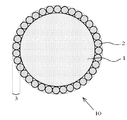
- FIG. 1A is a cross-sectional view of light-reflective conductive particles used in the light-reflective anisotropic conductive adhesive of the present invention.
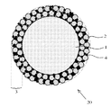
- FIG. 1B is a cross-sectional view of light-reflective conductive particles used in the light-reflective anisotropic conductive adhesive of the present invention.
- FIG. 2 is a cross-sectional view of the light emitting device of the present invention.
- FIG. 3 is a cross-sectional view of a conventional light emitting device.
- FIG. 4 is a cross-sectional view of a conventional light emitting device.
- the light-reflective anisotropic conductive adhesive of the present invention is used for anisotropic conductive connection of a light-emitting element to a wiring board, and includes a thermosetting resin composition, conductive particles, and a light-reflective needle-like shape. Insulating particles and light-reflective spherical insulating particles are contained.
- the reason why the light-reflective acicular insulating particles and the light-reflective spherical insulating particles are used in combination as the light-reflective insulating particles is as follows.
- the light-reflective insulating particles are contained in the thermosetting resin composition
- the stretchability of the resin composition decreases (hardens) with temperature change
- the thermosetting resin composition or thru Cracks are likely to occur at the interface between the light-reflective insulating particles and the thermosetting resin composition due to the internal stress of the cured product. If a crack occurs in the light-reflective anisotropic conductive adhesive, conduction reliability is impaired. Therefore, the light-reflective anisotropic conductive adhesive needs to have excellent toughness, but by adding light-reflective acicular insulating particles as light-reflective insulating particles to the thermosetting resin composition. High toughness can be imparted to the light-reflective anisotropic conductive adhesive.
- thermosetting resin composition the needle-like light-reflective insulating particles arranged in random directions are easy to bend and bend themselves, so that the thermosetting resin accompanying the temperature change.
- the internal stress of the composition can be propagated and absorbed in the needle-like crystal, and the internal stress can be suppressed from being transmitted to the thermosetting resin composition. Therefore, the light-reflective anisotropic conductive adhesive containing light-reflective acicular insulating particles exhibits excellent toughness, and does not generate cracks even if the thermosetting resin composition expands or contracts due to temperature changes. It is possible to suppress or prevent, and to suppress or prevent a decrease in conduction reliability.
- the light-reflective acicular insulating particles when only the light-reflective acicular insulating particles are used as the light-reflective insulating particles, the light reflectance tends to decrease. Therefore, in the present invention, spherical light-reflective insulating particles having good light reflection characteristics are used in combination with light-reflective needle-like insulating particles.
- the blending amount of such light-reflective needle-like insulating particles in the thermosetting resin composition is 1 to 50% by volume, preferably 5 to 25% by volume with respect to the thermosetting resin composition. This is because if the blending amount of the light-reflective needle-like insulating particles is less than 1% by volume, the occurrence of cracks in the joint due to the light-reflective anisotropic conductive adhesive and the deterioration of the conduction reliability are sufficiently suppressed or prevented.
- the amount of the thermosetting resin composition is relatively reduced, the adhesiveness of the light-reflective anisotropic conductive adhesive is lowered, and the light-reflective spherical insulating particles This is because there is a tendency that the improvement of the light reflectivity of the joint by the light-reflective anisotropic conductive adhesive tends to be insufficient, and the effect of the present invention can be obtained within this range.
- the blending amount of the light-reflective spherical insulating particles in the thermosetting resin composition is 1 to 50% by volume, preferably 2 to 25% by volume with respect to the thermosetting resin composition. This is because when the blending amount of the light-reflective spherical insulating particles is less than 1% by volume, the light reflectivity of the joint by the light-reflective anisotropic conductive adhesive tends to be insufficiently improved.
- the amount of the thermosetting resin composition is relatively reduced, the adhesiveness of the light-reflective anisotropic conductive adhesive is lowered, and the amount of the light-reflective acicular insulating particles is also reduced, thereby reflecting light. This is because it is difficult to suppress the occurrence of cracks in the joint due to the anisotropic anisotropic conductive adhesive and to make it difficult to improve the decrease in conduction reliability, and the effect of the present invention can be obtained within this range.
- the blending ratio (V / V) of the light-reflective spherical insulating particles to the light-reflective needle-like insulating particles is 1: 1 to 10, preferably 1: 2 to 8.
- the blending amount of the light-reflective spherical insulating particles is out of this range and is relatively smaller than the light-reflective needle-like insulating particles, the light-reflecting properties tend to deteriorate, and conversely, the amount is relatively large. This is because crack resistance tends to be reduced.
- the light-reflective acicular insulating particles it is preferable to use a white acicular inorganic compound when applied to a light-emitting device that emits visible light.
- a white acicular inorganic compound when applied to a light-emitting device that emits visible light.
- Such light-reflective needle-like insulating particles reflect the light incident on the light-reflective anisotropic conductive adhesive to the outside, and the light-reflective needle-like insulating particles themselves exhibit a white color. The wavelength dependence of the light reflection characteristics can be reduced, and visible light can be efficiently reflected.
- the diameter of the light-reflective needle-like insulating particles is preferably 5 ⁇ m or less. Further, the aspect ratio is preferably larger than 10 in order to sufficiently propagate and absorb the internal stress of the thermosetting resin composition, and the light-reflective needle-like insulating particles are hardly broken, In order to disperse uniformly in the curable resin composition, it is preferably less than 35. In order to further improve the dispersibility in the thermosetting resin composition, it is more preferably less than 20.
- Preferred specific examples of such light-reflective acicular insulating particles include zinc oxide whisker, titanium oxide whisker, potassium titanate whisker, titanate whisker such as sodium titanate whisker, aluminum borate whisker, wollastonite.
- white needle-shaped inorganic particles such as (kaline silicate needle crystals). These can use 1 type, or 2 or more types.
- the whisker is a crystal grown in a needle shape by a special manufacturing method, and since there is no disorder in the crystal structure, it has an advantage that it is highly elastic and hardly deformed. Since these inorganic compounds exhibit white color in a light emitting device that emits visible light, the wavelength dependency of the light reflection property with respect to visible light is small, and visible light is easily reflected.
- the zinc oxide whisker has a high whiteness and is a catalyst for photodegradation even when photocuring of the cured product of the thermosetting resin composition in the cured anisotropic conductive adhesive is concerned. It is particularly preferable because it has no property.
- the light-reflective acicular insulating particles are formed by combining the center and apex of a tetrahedron such as Tetrapod (registered trademark) instead of such a single acicular crystal. You may make it use the crystal
- the white needle-like inorganic particles of double needle crystals are superior in that they have a higher thermal conductivity than the white needle-like inorganic particles of single needle crystals, but have a bulkier crystal structure than single needle crystals. Therefore, it is necessary to be careful not to damage the substrate or the joined part of the element by the needle-like part during thermocompression bonding.
- These light-reflective needle-like insulating particles may be treated with a silane coupling agent, for example.
- a silane coupling agent for example.
- the dispersibility thereof in the thermosetting resin composition can be improved.
- the light-reflective acicular insulating particles obtained by treating acicular inorganic particles, preferably zinc oxide whiskers with a silane coupling agent can be uniformly mixed in the thermosetting resin composition in a short time. it can.
- the light-reflective needle-like insulating particles have a refractive index (JIS K7142) that is preferably larger than the refractive index (JIS K7142) of the cured product of the thermosetting resin composition, more preferably at least about 0.02. It is preferable. This is because if the difference in refractive index is small, the light reflection efficiency at the interface between them will decrease.
- the light-reflective spherical insulating particles used in combination with the light-reflective acicular insulating particles use a spherical inorganic compound that exhibits white when applied to a light-emitting device that emits visible light. It is preferable to do.
- Such light-reflective spherical insulating particles reflect the light incident on the light-reflective anisotropic conductive adhesive to the outside, and the light-reflective spherical insulating particles themselves exhibit a white color, so that light reflection with respect to visible light is performed. The wavelength dependency of characteristics can be reduced, and visible light can be efficiently reflected.
- the thickness is preferably 0.02 to 20 ⁇ m, more preferably 0.2 to 1 ⁇ m.
- Such light-reflective spherical insulating particles are selected from the group consisting of titanium oxide (TiO 2 ), boron nitride (BN), zinc oxide (ZnO), and aluminum oxide (Al 2 O 3 ). At least one kind of inorganic particles may be mentioned. Among these, it is preferable to use TiO 2 from the viewpoint of a high refractive index. Moreover, you may form Si and Al coat layer in these surfaces by a conventional method as needed.
- the light-reflective spherical insulating particles have a refractive index (JIS K7142) that is preferably larger than the refractive index of the cured product of the thermosetting resin composition (JIS K7142), more preferably at least about 0.02. Is preferred. This is because if the difference in refractive index is small, the light reflection efficiency at the interface between them decreases.
- the light-reflective spherical insulating particles resin-coated metal particles in which the surface of the spherical metal particles is coated with a transparent insulating resin can be used.
- the metal material for the spherical metal particles include nickel, silver, and aluminum. Among them, silver is preferable.
- the average particle diameter of the resin-coated metal particles as the light-reflective spherical insulating particles varies depending on the shape. Generally, if the particle diameter is too large, the anisotropic conductive connection by the conductive particles may be inhibited, and if it is too small, the light is reflected. Therefore, it is preferably 0.1 to 30 ⁇ m, and more preferably 0.2 to 10 ⁇ m.
- the average particle diameter of the resin-coated metal particles is a size including the insulating coating.
- the resin in the resin-coated metal particles as such light-reflective spherical insulating particles various insulating resins can be used. From the standpoint of mechanical strength and transparency, a cured product of acrylic resin can be preferably used.
- a preferable example is a resin obtained by radical copolymerization of methyl methacrylate and 2-hydroxyethyl methacrylate in the presence of a radical polymerization initiator such as an organic peroxide such as benzoyl peroxide. In this case, it is more preferably crosslinked with an isocyanate-based crosslinking agent such as 2,4-tolylene diisocyanate.
- the metal particles it is preferable to introduce a ⁇ -glycidoxy group, a vinyl group, or the like into the metal surface in advance with a silane coupling agent.
- Such resin-coated metal particles are prepared, for example, by putting metal particles and a silane coupling agent in a solvent such as toluene and stirring for about 1 hour at room temperature, and then, if necessary, a radical monomer and a radical polymerization initiator. Then, a crosslinking agent is added, and the mixture is stirred by heating to the radical polymerization starting temperature.
- metal particles used in conventional conductive particles for anisotropic conductive connection can be used.
- examples thereof include gold, nickel, copper, silver, solder, palladium, aluminum, alloys thereof, multilayered products thereof (for example, nickel plating / gold flash plating products), and the like.
- gold, nickel, and copper turn the conductive particles brown, so that the effects of the present invention can be enjoyed over other metal materials.
- metal-coated resin particles obtained by coating resin particles with a metal material can be used.
- resin particles include styrene resin particles, benzoguanamine resin particles, and nylon resin particles.
- a method of coating the resin particles with a metal material a conventionally known method can be employed, and an electroless plating method, an electrolytic plating method, or the like can be used.
- the layer thickness of the metal material to be coated is sufficient to ensure good conduction reliability, and is usually 0.1 to 3 ⁇ m although it depends on the particle size of the resin particles and the type of metal.
- the average particle size of the resin particles is preferably 1 to 20 ⁇ m, more preferably 3 to 10 ⁇ m, particularly preferably 3 to 5 ⁇ m. It is.
- the shape of the core particle 1 is preferably a spherical shape, but may be a flake shape or a rugby ball shape.
- the metal-coated resin particles have a spherical shape, and if the particle size is too large, the conduction reliability is lowered, so that it is preferably 1 to 20 ⁇ m, more preferably 3 to 10 ⁇ m.
- 1A and 1B are sectional views of such light-reflective conductive particles 10 and 20. First, the light reflective conductive particles in FIG. 1A will be described.
- the light-reflective conductive particles 10 are selected from core particles 1 coated with a metal material, and titanium oxide (TiO 2 ) particles, zinc oxide (ZnO) particles, or aluminum oxide (Al 2 O 3 ) particles on the surface thereof. And a light reflection layer 3 formed of at least one kind of inorganic particles 2. Titanium oxide particles, zinc oxide particles, or aluminum oxide particles are inorganic particles that exhibit a white color under sunlight. Accordingly, the light reflecting layer 3 formed from them exhibits white to gray.
- the expression of white to gray means that the wavelength dependence of the light reflection characteristic with respect to visible light is small and the visible light is easily reflected.
- Zinc oxide particles having no catalytic property and high refractive index can be preferably used.
- the surface thereof is made of a metal material.
- the surface is coated with a metal material, as described above, an aspect in which the core particle 1 itself is a metal material, or an aspect in which the surface of the resin particle is coated with a metal material can be given.
- the thickness of the light reflecting layer 3 formed from the inorganic particles 2 is too low with respect to the particle size of the core particle 1. If it is too large, poor conduction will occur. Therefore, it is preferably 0.5 to 50%, more preferably 1 to 25%.
- the thickness is preferably 0.02 to 4 ⁇ m, more preferably 0.1 to 1 ⁇ m, and particularly preferably 0.2 to 0.5 ⁇ m.
- the particle size of the inorganic particles 2 is set so that the light to be reflected (that is, the light emitted from the light emitting element) is not transmitted. It is preferable that it is 50% or more.
- examples of the shape of the inorganic particles 2 include an amorphous shape, a spherical shape, a scaly shape, and a needle shape.
- a spherical shape is preferable from the viewpoint of the light diffusion effect
- a scaly shape is preferable from the viewpoint of the total reflection effect.
- the light-reflective conductive particles 10 in FIG. 1A are formed by a known film forming technique (so-called mechano-fusion method) in which a film composed of small-sized particles is formed on the surface of large-sized particles by physically colliding large and small powders. ).
- the inorganic particles 2 are fixed so as to bite into the metal material on the surface of the core particle 1.
- a monolayer of inorganic particles constitutes the light reflecting layer 3. . Therefore, in the case of FIG. 1A, the layer thickness of the light reflecting layer 3 is considered to be equivalent to or slightly thinner than the particle size of the inorganic particles 2.
- the light reflective conductive particles 20 in FIG. 1B will be described.
- the light-reflecting layer 3 contains a thermoplastic resin 4 that functions as an adhesive
- the inorganic particles 2 are also fixed together by this thermoplastic resin 4, and the inorganic particles 2 are multilayered (for example, It differs from the light-reflective conductive particle 10 of FIG. 1A in that it is multi-layered into two or three layers.
- the mechanical strength of the light reflecting layer 3 is improved, and the inorganic particles 2 are hardly peeled off.
- thermoplastic resin 4 a halogen-free thermoplastic resin can be preferably used for the purpose of low environmental load, and for example, polyolefins such as polyethylene and polypropylene, polystyrene, acrylic resins and the like can be preferably used.
- Such light-reflective conductive particles 20 can also be manufactured by a mechanofusion method. If the particle size of the thermoplastic resin 4 applied to the mechano-fusion method is too small, the adhesion function is lowered, and if it is too large, it is difficult to adhere to the core particle 1, so that it is preferably 0.02 to 4 ⁇ m, more preferably 0.8. 1 to 1 ⁇ m. Further, if the blending amount of the thermoplastic resin 4 is too small, the adhesive function is lowered, and if it is too large, aggregates of light-reflective conductive particles and core particles are formed. The amount is preferably 0.2 to 500 parts by mass, more preferably 4 to 25 parts by mass.
- thermosetting resin composition used for the light-reflective anisotropic conductive adhesive of the present invention it is preferable to use a colorless and transparent one as much as possible. This is because the light-reflecting conductive particles in the light-reflective anisotropic conductive adhesive are reflected without decreasing the light reflection efficiency and without changing the light color of the incident light.
- the colorless and transparent means that the cured product of the thermosetting resin composition has a light transmittance (JIS K7105) of 80% or more, preferably 90% or more with respect to visible light having a wavelength of 380 to 780 nm with an optical path length of 1 cm.
- the amount of conductive particles such as light-reflective conductive particles with respect to 100 parts by mass of the thermosetting resin composition is too small, conduction failure occurs, and if it is too large, a pattern is formed. Since a short circuit tends to occur, the amount is preferably 1 to 100 parts by mass, more preferably 10 to 50 parts by mass.
- the light reflection property of the light reflective anisotropic conductive adhesive of the present invention is such that the light reflectance anisotropic conductive adhesive cured product of the light reflective anisotropic conductive adhesive with respect to light having a wavelength of 450 nm ( It is desirable that JIS K7105) is at least 30%.
- the light reflection characteristics and blending amount of the light reflecting conductive particles to be used, the blending composition of the thermosetting resin composition, and the like may be appropriately adjusted. Usually, if the amount of the light-reflective conductive particles having good light reflection characteristics is increased, the reflectance tends to increase.
- the light reflection characteristics of the light reflective anisotropic conductive adhesive can be evaluated from the viewpoint of refractive index. That is, if the refractive index of the cured product is larger than the refractive index of the cured product of the thermosetting resin composition excluding the conductive particles, light-reflective acicular insulating particles, and light-reflective spherical insulating particles, This is because the amount of light reflection at the interface between the conductive needle-like insulating particles and the light-reflective spherical insulating particles and the cured product of the thermosetting resin composition surrounding them increases.
- the difference obtained by subtracting the refractive index (JIS K7142) of the cured product of the thermosetting resin composition from the refractive index (JIS K7142) of each of the light reflective needle-like insulating particles and the light reflective spherical insulating particles is preferably 0.02 or more, more preferably 0.2 or more.
- the refractive index of a thermosetting resin composition mainly composed of an epoxy resin is about 1.5.
- thermosetting resin composition constituting the light-reflective anisotropic conductive adhesive of the present invention
- those used in conventional anisotropic conductive adhesives and anisotropic conductive films can be used.
- thermosetting resin composition is obtained by blending a curing agent with an insulating binder resin.
- the insulating binder resin is preferably an epoxy resin mainly composed of an alicyclic epoxy compound, a heterocyclic epoxy compound, a hydrogenated epoxy compound, or the like.
- Preferred examples of the alicyclic epoxy compound include those having two or more epoxy groups in the molecule. These may be liquid or solid. Specific examples include glycidyl hexahydrobisphenol A, 3,4-epoxycyclohexenylmethyl-3,4'-epoxycyclohexene carboxylate, and the like. Among these, glycidyl hexahydrobisphenol A, 3,4-epoxycyclohexenylmethyl-3 ′, 4 is preferable because it can ensure light transmission suitable for mounting LED elements on the cured product and is excellent in rapid curing. '-Epoxycyclohexenecarboxylate can be preferably used.
- heterocyclic epoxy compound examples include an epoxy compound having a triazine ring, and 1,3,5-tris (2,3-epoxypropyl) -1,3,5-triazine-2,4 is particularly preferable. , 6- (1H, 3H, 5H) -trione.
- hydrogenated epoxy compound hydrogenated products of the above-described alicyclic epoxy compounds and heterocyclic epoxy compounds, and other known hydrogenated epoxy resins can be used.
- the alicyclic epoxy compound, heterocyclic epoxy compound and hydrogenated epoxy compound may be used alone, but two or more kinds may be used in combination.
- other epoxy compounds may be used in combination as long as the effects of the present invention are not impaired.
- the curing agent examples include acid anhydrides, imidazole compounds, and dicyan.
- an acid anhydride-based curing agent that hardly changes the color of the cured product particularly an alicyclic acid anhydride-based curing agent, can be preferably used.
- methylhexahydrophthalic anhydride etc. can be mentioned preferably.
- thermosetting resin composition of the light-reflective anisotropic conductive adhesive of the present invention when an alicyclic epoxy compound and an alicyclic acid anhydride-based curing agent are used, the respective amounts used are alicyclic. If the amount of the acid anhydride-based curing agent is too small, the amount of the uncured epoxy compound increases, and if the amount is too large, the corrosion of the adherend material tends to be accelerated by the influence of the excess curing agent.
- the alicyclic acid anhydride curing agent is preferably used in an amount of 80 to 120 parts by mass, more preferably 95 to 105 parts by mass with respect to parts by mass.
- the light-reflective anisotropic conductive adhesive of the present invention can be produced by uniformly mixing light-reflective needle-like insulating particles and light-reflective spherical insulating particles, conductive particles, and a thermosetting resin composition. it can.
- the light-reflective anisotropic conductive adhesive of the present invention is used as a light-reflective anisotropic conductive film
- the light-reflective acicular insulating particles, the light-reflective spherical insulating particles, the conductive particles, and the thermosetting property may be dispersed and mixed with a solvent such as toluene, applied to the peeled PET film so as to have a desired thickness, and dried at a temperature of about 80 ° C.
- the light-emitting device 200 includes the connection terminal 22 on the substrate 21 and the connection bumps 26 formed on the n-electrode 24 and the p-electrode 25 of the LED element 23 as light-emitting elements.
- This is a light emitting device in which a light reflective anisotropic conductive adhesive is applied and the substrate 21 and the LED element 23 are flip-chip mounted.
- the cured product 100 of the light-reflective anisotropic conductive adhesive is composed of the light-reflective conductive particles 10, and further the light-reflective needle-like insulating particles and the light-reflective spherical insulating particles made of the thermosetting resin composition. Dispersed in the cured product 11.
- you may seal with transparent mold resin so that the whole LED element 23 may be covered as needed.
- you may provide a light reflection layer in the LED element 23 similarly to the past.
- the light emitting device 200 configured as described above, among the light emitted from the LED elements 23, the light emitted toward the substrate 21 is the light in the cured product 100 of the light-reflective anisotropic conductive adhesive.
- the light is reflected by the reflective conductive particles 10 and emitted from the upper surface of the LED element 23. Accordingly, it is possible to prevent a decrease in luminous efficiency.
- the light-reflective acicular insulating particles are included, the conduction reliability of the cured product of the light-reflective anisotropic conductive adhesive can be improved, and the occurrence of cracks can be suppressed or prevented.
- Configurations other than the light-reflective anisotropic conductive adhesive (the LED element 23, the bump 26, the substrate 21, the connection terminal 22, and the like) in the light-emitting device 200 of the present invention can be the same as the configuration of the conventional light-emitting device. .
- the light emitting device 200 of the present invention can be manufactured by using a conventional anisotropic conductive connection technique except that the light reflective anisotropic conductive adhesive of the present invention is used.
- a well-known light emitting element can be applied in the range which does not impair the effect of this invention other than an LED element.
- Examples 1-7, Comparative Examples 1-4 (Production of anisotropic conductive adhesive) Light-reflecting white needle-like insulating particles (metal oxide whiskers) and / or light-reflecting white spherical insulating particles (metal oxide particles) and conductive particles formed with a gold plating layer on the surface of spherical acrylic resin particles 10 parts by weight of light-reflective conductive particles (average particle diameter 5 ⁇ m) coated with gold-coated resin particles (average particle diameter 5 ⁇ m) or titanium oxide fine particles 50 parts by weight of an alicyclic epoxy compound (CEL2021P, Daicel Corporation) And an epoxy conductive thermosetting resin composition (refractive index: 1.45) containing 50 parts by mass of methylhexahydrophthalic anhydride to prepare an anisotropic conductive adhesive. did.
- the light-reflective conductive particles used in Example 6 were 4 parts by mass of titanium oxide powder having a particle size of 0.5 ⁇ m, 3 parts by mass of polystyrene-based powder having a particle size of 0.2 ⁇ m, and conductive particles having a particle size of 5 ⁇ m (average Mechano-fusion device (AMS-GMP, Hosokawa Micron) with 20 parts by mass of electroless gold plated particles (20 GNR 4.6EH, Nippon Chemical Industry Co., Ltd.) on spherical acrylic resin particles with a particle size of 4.6 ⁇ m And a light reflecting layer made of titanium oxide particles having a thickness of about 1 ⁇ m was formed on the surface of the gold-coated resin particles. The appearance color of the light reflective conductive particles was gray.
- AMS-GMP Average Mechano-fusion device
- electroless gold plated particles (20 GNR 4.6EH, Nippon Chemical Industry Co., Ltd.
- the light-reflective white spherical insulating particles used in Examples 1 and 2 are obtained by coating the surface of TiO 2 having a particle diameter of 0.5 ⁇ m with a Si film and an Al film.
- the light-reflective white needle-like insulating particles used in Example 6 are obtained by surface-treating (silica treatment) the surface of ZnO whiskers with a silicon coupling agent (Panatetra, Amtec Co., Ltd.).
- the produced anisotropic conductive adhesive was applied on a white plate so as to have a thickness of 100 ⁇ m, and was cured by heating at 200 ° C. for 1 minute.
- the total reflectance (specular reflection and diffuse reflection) with respect to the light of wavelength 450nm which used barium sulfate as a standard was measured using the spectrophotometer (UV3100, Shimadzu Corporation Corp.). The obtained results are shown in Table 1. In practice, it is desirable that the light reflectance is more than 30%.
- ⁇ TCT-A> The test LED module was exposed to an atmosphere of ⁇ 40 ° C. and 100 ° C. for 30 minutes each, and 1000 cycles of a cooling / heating cycle were performed.
- ⁇ TCT-B> The test LED module was exposed to an atmosphere of ⁇ 55 ° C. and 125 ° C. for 30 minutes each, and 1000 cycles of cooling and heating cycles were performed with this as one cycle.
- the test LED module taken out from TCT was observed from the upper surface of the blue LED element with a metal microscope, and the light-reflective anisotropic conductive adhesive was Whether or not cracks occurred in the cured product was observed and evaluated according to the following criteria.
- the total amount of the light-reflective insulating particles is the same as that of the anisotropic conductive adhesive of Example 3, but the light-reflective white spherical insulating particles are used. Since only light-reflective white needle-like insulating particles were used without blending, the total reflectance was reduced from 42% (Example 3) to 35%, and the total luminous flux was also reduced from 360 mlm (Example 3) to 300 mlm. did.
- the total blending amount of the light reflective insulating particles is the same as that of the anisotropic conductive adhesive of Example 3, but the light reflective white needle-like insulating particles are blended. Since only the light-reflective white spherical insulating particles were used, the total reflectance was improved from 42% (Example 3) to 50%, but the crack resistance was evaluated as “C”, and the conduction reliability was improved. In the case of TCT-B, the evaluation was “B”.
- the light-reflective anisotropic conductive adhesive of the present invention contains light-reflective needle-like insulating particles and spherical insulating particles in an amount of 1 to 50% by volume with respect to the thermosetting resin composition, respectively.
- the mixing ratio of the spherical insulating particles to the light-reflecting needle-like insulating particles is set to 1: 1 to 10. For this reason, it is possible to improve the light emission efficiency without providing a light reflection layer on the LED element that causes an increase in manufacturing cost, and to reduce the conduction reliability that occurs in the anisotropic conductive connection portion of the light emitting device due to a change in environmental temperature. And the generation of cracks can be suppressed or prevented. Therefore, the light-reflective anisotropic conductive adhesive of the present invention is useful when the LED element is flip-lip mounted.
Landscapes
- Chemical & Material Sciences (AREA)
- Organic Chemistry (AREA)
- Led Device Packages (AREA)
- Adhesives Or Adhesive Processes (AREA)
Abstract
Priority Applications (4)
| Application Number | Priority Date | Filing Date | Title |
|---|---|---|---|
| KR1020137023354A KR101911564B1 (ko) | 2011-03-07 | 2012-02-23 | 광반사성 이방성 도전 접착제 및 발광 장치 |
| EP12755243.8A EP2685513B1 (fr) | 2011-03-07 | 2012-02-23 | Adhésif conducteur anisotrope réfléchissant la lumière et dispositif électroluminescent |
| US13/995,033 US20130264602A1 (en) | 2011-03-07 | 2012-02-23 | Light-reflective anisotropic conductive adhesive and light-emitting device |
| CN201280011864.2A CN103403896B (zh) | 2011-03-07 | 2012-02-23 | 光反射性各向异性导电粘接剂以及发光装置 |
Applications Claiming Priority (2)
| Application Number | Priority Date | Filing Date | Title |
|---|---|---|---|
| JP2011-048625 | 2011-03-07 | ||
| JP2011048625A JP5609716B2 (ja) | 2011-03-07 | 2011-03-07 | 光反射性異方性導電接着剤及び発光装置 |
Publications (1)
| Publication Number | Publication Date |
|---|---|
| WO2012121021A1 true WO2012121021A1 (fr) | 2012-09-13 |
Family
ID=46797990
Family Applications (1)
| Application Number | Title | Priority Date | Filing Date |
|---|---|---|---|
| PCT/JP2012/054411 Ceased WO2012121021A1 (fr) | 2011-03-07 | 2012-02-23 | Adhésif conducteur anisotrope réfléchissant la lumière et dispositif électroluminescent |
Country Status (7)
| Country | Link |
|---|---|
| US (1) | US20130264602A1 (fr) |
| EP (1) | EP2685513B1 (fr) |
| JP (1) | JP5609716B2 (fr) |
| KR (1) | KR101911564B1 (fr) |
| CN (1) | CN103403896B (fr) |
| TW (1) | TWI553088B (fr) |
| WO (1) | WO2012121021A1 (fr) |
Cited By (2)
| Publication number | Priority date | Publication date | Assignee | Title |
|---|---|---|---|---|
| DE102013104195A1 (de) * | 2013-04-25 | 2014-10-30 | Osram Opto Semiconductors Gmbh | Optoelektronisches Bauelement und Verfahren zu seiner Herstellung |
| CN105531835A (zh) * | 2013-09-13 | 2016-04-27 | 欧司朗光电半导体有限公司 | 光电子半导体组件和用于制造光电子半导体组件的方法 |
Families Citing this family (24)
| Publication number | Priority date | Publication date | Assignee | Title |
|---|---|---|---|---|
| JP5617210B2 (ja) * | 2009-09-14 | 2014-11-05 | デクセリアルズ株式会社 | 光反射性異方性導電接着剤及び発光装置 |
| JP5916334B2 (ja) * | 2011-10-07 | 2016-05-11 | デクセリアルズ株式会社 | 異方性導電接着剤及びその製造方法、発光装置及びその製造方法 |
| KR101513641B1 (ko) * | 2013-08-20 | 2015-04-22 | 엘지전자 주식회사 | 표시장치 |
| JP6292808B2 (ja) | 2013-09-13 | 2018-03-14 | デクセリアルズ株式会社 | 接着剤、及び発光装置 |
| EP3051598A4 (fr) | 2013-09-26 | 2017-06-28 | Dexerials Corporation | Dispositif émetteur de lumière, adhésif conducteur anisotrope et procédé de fabrication d'un dispositif émetteur de lumière |
| JP6450923B2 (ja) * | 2013-12-20 | 2019-01-16 | パナソニックIpマネジメント株式会社 | 電子部品実装システムおよび電子部品実装方法ならびに電子部品実装装置 |
| US9812625B2 (en) | 2014-02-18 | 2017-11-07 | Nichia Corporation | Light-emitting device having resin member with conductive particles |
| JP6347635B2 (ja) * | 2014-03-19 | 2018-06-27 | デクセリアルズ株式会社 | 異方性導電接着剤 |
| WO2015178482A1 (fr) | 2014-05-23 | 2015-11-26 | デクセリアルズ株式会社 | Agent adhésif et structure à liaisons |
| EP3273493B1 (fr) | 2015-03-18 | 2022-03-02 | Dexerials Corporation | Procédé de fabrication d'un dispositif d'émission de lumière |
| DE102015112967A1 (de) * | 2015-08-06 | 2017-02-09 | Osram Opto Semiconductors Gmbh | Verfahren zum Herstellen eines optoelektronischen Bauelements und optoelektronisches Bauelement |
| TWI569473B (zh) * | 2015-08-26 | 2017-02-01 | 邱羅利士公司 | 封裝結構及其製法 |
| CN105552192A (zh) * | 2015-12-08 | 2016-05-04 | 李小鹏 | 一种多晶反射绝缘板及其制备方法 |
| TWM521008U (zh) * | 2016-01-27 | 2016-05-01 | 光寶科技股份有限公司 | 車燈裝置及其發光模組 |
| DE102016106494A1 (de) * | 2016-04-08 | 2017-10-12 | Osram Opto Semiconductors Gmbh | Optoelektronisches bauelement und verfahren zum herstellen eines optoelektronischen bauelements |
| JP2018088498A (ja) * | 2016-11-29 | 2018-06-07 | デクセリアルズ株式会社 | 異方性導電接着剤 |
| JP6868388B2 (ja) * | 2016-12-26 | 2021-05-12 | 日亜化学工業株式会社 | 発光装置および集積型発光装置 |
| JP7014948B2 (ja) * | 2017-06-13 | 2022-02-02 | 日亜化学工業株式会社 | 発光装置の製造方法および発光装置 |
| CN111788275B (zh) * | 2018-03-01 | 2021-12-03 | 住友电木株式会社 | 糊状粘接剂组合物和半导体装置 |
| CN112740338B (zh) * | 2018-11-07 | 2022-09-06 | 日本化学工业株式会社 | 包覆颗粒和包含其的导电性材料、和包覆颗粒的制造方法 |
| CN110283561B (zh) * | 2019-05-30 | 2021-09-10 | 天津德高化成科技有限公司 | 一种led显示屏贴片式分立器件用封装树脂组合物及其用途 |
| JP2021103609A (ja) | 2019-12-24 | 2021-07-15 | デクセリアルズ株式会社 | 異方性導電フィルム |
| WO2021261427A1 (fr) * | 2020-06-22 | 2021-12-30 | 日東電工株式会社 | Composition de résine de renfort de jonction d'élément optique et module optique l'utilisant |
| JP7464862B2 (ja) * | 2022-04-21 | 2024-04-10 | 日亜化学工業株式会社 | 発光装置、光源 |
Citations (5)
| Publication number | Priority date | Publication date | Assignee | Title |
|---|---|---|---|---|
| JPH11168235A (ja) | 1997-12-05 | 1999-06-22 | Toyoda Gosei Co Ltd | 発光ダイオード |
| JPH11343465A (ja) * | 1998-06-01 | 1999-12-14 | Fujitsu Ltd | 接着剤、接着方法及び実装基板の組み立て体 |
| JP2001332124A (ja) * | 2000-05-22 | 2001-11-30 | Toshiba Chem Corp | 導電性ペーストおよび光半導体装置 |
| JP2008192880A (ja) * | 2007-02-06 | 2008-08-21 | Nichia Chem Ind Ltd | 発光装置及びその製造方法並びに発光装置用成形体 |
| JP2010225597A (ja) * | 2009-02-27 | 2010-10-07 | Sony Chemical & Information Device Corp | 異方性導電フィルム及び発光装置 |
Family Cites Families (8)
| Publication number | Priority date | Publication date | Assignee | Title |
|---|---|---|---|---|
| CA1334479C (fr) * | 1988-08-29 | 1995-02-21 | Matsushita Electric Industrial Co., Ltd. | Substance conductrice et sa methode de fabrication |
| JP3637277B2 (ja) * | 2000-03-21 | 2005-04-13 | 大塚化学ホールディングス株式会社 | 難燃剤、及び難燃性樹脂組成物、及び成形物、及び電子部品 |
| US20050228097A1 (en) * | 2004-03-30 | 2005-10-13 | General Electric Company | Thermally conductive compositions and methods of making thereof |
| WO2008053753A1 (fr) * | 2006-10-31 | 2008-05-08 | Techno Polymer Co., Ltd. | Composition de résine dissipatrice de chaleur, substrat pour montage de led, réflecteur, et substrat pour montage de led comportant une partie réflecteur |
| JP2009197185A (ja) * | 2008-02-25 | 2009-09-03 | Hitachi Chem Co Ltd | 透明熱伝導接着フィルム及びその用途 |
| JP5422921B2 (ja) * | 2008-05-28 | 2014-02-19 | デクセリアルズ株式会社 | 接着フィルム |
| JP5126175B2 (ja) * | 2009-07-27 | 2013-01-23 | 住友ベークライト株式会社 | 金属含有ペーストおよび半導体装置 |
| KR101829475B1 (ko) * | 2010-06-09 | 2018-02-14 | 데쿠세리아루즈 가부시키가이샤 | 광반사성 이방성 도전 페이스트 및 발광 장치 |
-
2011
- 2011-03-07 JP JP2011048625A patent/JP5609716B2/ja active Active
-
2012
- 2012-02-23 KR KR1020137023354A patent/KR101911564B1/ko active Active
- 2012-02-23 WO PCT/JP2012/054411 patent/WO2012121021A1/fr not_active Ceased
- 2012-02-23 EP EP12755243.8A patent/EP2685513B1/fr active Active
- 2012-02-23 US US13/995,033 patent/US20130264602A1/en not_active Abandoned
- 2012-02-23 CN CN201280011864.2A patent/CN103403896B/zh active Active
- 2012-02-29 TW TW101106490A patent/TWI553088B/zh active
Patent Citations (5)
| Publication number | Priority date | Publication date | Assignee | Title |
|---|---|---|---|---|
| JPH11168235A (ja) | 1997-12-05 | 1999-06-22 | Toyoda Gosei Co Ltd | 発光ダイオード |
| JPH11343465A (ja) * | 1998-06-01 | 1999-12-14 | Fujitsu Ltd | 接着剤、接着方法及び実装基板の組み立て体 |
| JP2001332124A (ja) * | 2000-05-22 | 2001-11-30 | Toshiba Chem Corp | 導電性ペーストおよび光半導体装置 |
| JP2008192880A (ja) * | 2007-02-06 | 2008-08-21 | Nichia Chem Ind Ltd | 発光装置及びその製造方法並びに発光装置用成形体 |
| JP2010225597A (ja) * | 2009-02-27 | 2010-10-07 | Sony Chemical & Information Device Corp | 異方性導電フィルム及び発光装置 |
Non-Patent Citations (1)
| Title |
|---|
| See also references of EP2685513A4 |
Cited By (5)
| Publication number | Priority date | Publication date | Assignee | Title |
|---|---|---|---|---|
| DE102013104195A1 (de) * | 2013-04-25 | 2014-10-30 | Osram Opto Semiconductors Gmbh | Optoelektronisches Bauelement und Verfahren zu seiner Herstellung |
| US9620674B2 (en) | 2013-04-25 | 2017-04-11 | Osram Opto Semiconductors Gmbh | Optoelectronic component and method for the production thereof |
| CN105531835A (zh) * | 2013-09-13 | 2016-04-27 | 欧司朗光电半导体有限公司 | 光电子半导体组件和用于制造光电子半导体组件的方法 |
| US20160218261A1 (en) * | 2013-09-13 | 2016-07-28 | Osram Opto Semiconductors Gmbh | Optoelectronic semiconductor component and method of fabricating an optoelectronic semiconductor component |
| CN105531835B (zh) * | 2013-09-13 | 2018-11-23 | 欧司朗光电半导体有限公司 | 光电子半导体组件和用于制造光电子半导体组件的方法 |
Also Published As
| Publication number | Publication date |
|---|---|
| CN103403896B (zh) | 2016-10-05 |
| US20130264602A1 (en) | 2013-10-10 |
| JP2012186322A (ja) | 2012-09-27 |
| CN103403896A (zh) | 2013-11-20 |
| JP5609716B2 (ja) | 2014-10-22 |
| EP2685513A4 (fr) | 2014-12-31 |
| KR20140052950A (ko) | 2014-05-07 |
| TW201241145A (en) | 2012-10-16 |
| EP2685513A1 (fr) | 2014-01-15 |
| EP2685513B1 (fr) | 2015-10-21 |
| KR101911564B1 (ko) | 2018-10-24 |
| TWI553088B (zh) | 2016-10-11 |
Similar Documents
| Publication | Publication Date | Title |
|---|---|---|
| JP5609716B2 (ja) | 光反射性異方性導電接着剤及び発光装置 | |
| JP5617210B2 (ja) | 光反射性異方性導電接着剤及び発光装置 | |
| JP5402804B2 (ja) | 発光装置の製造方法 | |
| JP5526698B2 (ja) | 光反射性導電粒子、異方性導電接着剤及び発光装置 | |
| JP5555038B2 (ja) | 光反射性異方性導電接着剤及び発光装置 | |
| JP5958107B2 (ja) | 光反射性異方性導電接着剤及び発光装置 | |
| WO2012144033A1 (fr) | Particules conductrices réfléchissant la lumière, adhésif conducteur anisotrope et dispositif électroluminescent | |
| WO2014013984A1 (fr) | Agent adhésif électroconducteur anisotrope réfléchissant la lumière, et dispositif électroluminescent | |
| JP5785306B2 (ja) | 光反射性異方性導電接着剤及び発光装置 | |
| JP2014030026A (ja) | 異方性導電接着剤及び発光装置 | |
| HK1191450A (en) | Light-reflective anisotropic conductive adhesive and light-emitting device | |
| HK1191450B (en) | Light-reflective anisotropic conductive adhesive and light-emitting device | |
| HK1178320B (en) | Light-reflective anisotropic conductive adhesive agent, and light emitting device |
Legal Events
| Date | Code | Title | Description |
|---|---|---|---|
| 121 | Ep: the epo has been informed by wipo that ep was designated in this application |
Ref document number: 12755243 Country of ref document: EP Kind code of ref document: A1 |
|
| WWE | Wipo information: entry into national phase |
Ref document number: 13995033 Country of ref document: US |
|
| WWE | Wipo information: entry into national phase |
Ref document number: 2012755243 Country of ref document: EP |
|
| ENP | Entry into the national phase |
Ref document number: 20137023354 Country of ref document: KR Kind code of ref document: A |
|
| NENP | Non-entry into the national phase |
Ref country code: DE |