WO2012121186A1 - Connecteur - Google Patents
Connecteur Download PDFInfo
- Publication number
- WO2012121186A1 WO2012121186A1 PCT/JP2012/055509 JP2012055509W WO2012121186A1 WO 2012121186 A1 WO2012121186 A1 WO 2012121186A1 JP 2012055509 W JP2012055509 W JP 2012055509W WO 2012121186 A1 WO2012121186 A1 WO 2012121186A1
- Authority
- WO
- WIPO (PCT)
- Prior art keywords
- terminal fitting
- lance
- terminal
- locking
- connector
- Prior art date
- Legal status (The legal status is an assumption and is not a legal conclusion. Google has not performed a legal analysis and makes no representation as to the accuracy of the status listed.)
- Ceased
Links
Images


Classifications
-
- H—ELECTRICITY
- H01—ELECTRIC ELEMENTS
- H01R—ELECTRICALLY-CONDUCTIVE CONNECTIONS; STRUCTURAL ASSOCIATIONS OF A PLURALITY OF MUTUALLY-INSULATED ELECTRICAL CONNECTING ELEMENTS; COUPLING DEVICES; CURRENT COLLECTORS
- H01R13/00—Details of coupling devices of the kinds covered by groups H01R12/70 or H01R24/00 - H01R33/00
- H01R13/02—Contact members
- H01R13/10—Sockets for co-operation with pins or blades
- H01R13/11—Resilient sockets
-
- H—ELECTRICITY
- H01—ELECTRIC ELEMENTS
- H01R—ELECTRICALLY-CONDUCTIVE CONNECTIONS; STRUCTURAL ASSOCIATIONS OF A PLURALITY OF MUTUALLY-INSULATED ELECTRICAL CONNECTING ELEMENTS; COUPLING DEVICES; CURRENT COLLECTORS
- H01R13/00—Details of coupling devices of the kinds covered by groups H01R12/70 or H01R24/00 - H01R33/00
- H01R13/40—Securing contact members in or to a base or case; Insulating of contact members
- H01R13/42—Securing in a demountable manner
- H01R13/422—Securing in resilient one-piece base or case, e.g. by friction; One-piece base or case formed with resilient locking means
- H01R13/4223—Securing in resilient one-piece base or case, e.g. by friction; One-piece base or case formed with resilient locking means comprising integral flexible contact retaining fingers
Definitions
- the present invention relates to a connector constituted by a terminal fitting and a housing provided with a terminal accommodating portion for accommodating the terminal fitting.
- a wire harness is used to transmit electric power and control signals to the electronic device.
- the wire harness includes a plurality of electric wires and connectors.
- the connector includes a terminal fitting attached to the end of the electric wire and a housing provided with a plurality of terminal accommodating portions for accommodating the terminal fitting (for example, see Patent Document 1).
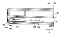
- FIG. 7 is a cross-sectional view showing a conventional connector disclosed in Patent Document 1.
- FIG. 8 is a perspective view showing a part of a terminal fitting constituting the connector shown in FIG.
- the terminal fitting 102 includes an electric wire connecting portion 103 connected to the electric wire 7, an electric contact portion 105 connected to the electric wire connecting portion 103 and connected to the other terminal fitting, A locking portion 145 provided on the electrical contact portion 105.
- the terminal fitting 102 is inserted into the terminal accommodating portion 161 along the longitudinal direction N thereof. Then, the locking portion 145 of the terminal fitting 102 is locked to the lance 165 of the terminal accommodating portion 161 and the terminal fitting 102 is accommodated in the terminal accommodating portion 161.
- the terminal fitting 102 connected to the electric wire 7 is prevented from coming out of the terminal accommodating portion 161 even when the electric wire 7 is pulled.
- the locking portion 145 is provided so as to protrude from the electrical contact portion 105 toward the lance 165 of the terminal accommodating portion 161. That is, the locking portion 145 is provided so as to protrude outward from the electrical contact portion 105.
- the locking portion 145 includes a locking protrusion 146 formed by driving an outer wall 105a constituting the electric contact portion 105 toward the outside of the electric contact portion 105 so that the electric wire connecting portion 103 side is opened.
- An inward projection 147 formed by a part of the stop projection 146 being driven out inward of the electrical contact portion 105.
- the locking portion 145 is formed in an inward protruding manner by the locking projection 146 being driven inward after the locking projection 146 is formed by driving the outer wall 105a of the electrical contact portion 105 outward. 147 is formed.
- the terminal accommodating portion 161 is provided with a lance 165 having one end connected to the inner surface of the terminal accommodating portion 161 and the other end being a free end.
- the lance 165 is provided at the center portion in the width direction of the terminal accommodating portion 161.
- the dimension along the width direction of the lance 165 is formed to be smaller than the dimension L along the width direction of the inward projection 147 provided on the terminal fitting 102.
- the locking portion 145 includes a locking projection 146 formed by driving the outer wall 105a of the electrical contact portion 105 outward, and the locking projection 146 is inward.
- the inwardly protruding portion 147 formed by being struck, and the dimension T1 struck in the outward direction of the locking protrusion 146 and the dimension struck inwardly of the inwardly protruding portion 147.
- a dimension T3 which is the sum of T2 is a margin for the lance 165 of the locking portion 145.
- the conventional connector 101 described above has the following problems.
- the locking portion 145 provided on the terminal fitting 102 of the connector 101 has the locking protrusion 146 formed on the inner side after the outer wall 105a of the electrical contact portion 105 is driven outward to form the locking protrusion 146. Since the inward projecting portion 147 is formed by being driven in the direction, the inward projecting portion 147 is formed, and at the same time, a concave recess 147 ′ is formed from the outer surface of the locking projecting portion 146. It will be done.
- the formation of the dent 147 ′ reduces the contact area of the locking portion 145 with the lance 165, thereby causing a problem that the holding force of the lance 165 with respect to the terminal fitting 102 is reduced.
- the locking portion 145 is formed in such a manner that the outer wall 105a of the electrical contact portion 105 is punched outward to form the locking protrusion 146, and then the locking protrusion 146 is driven inward to inwardly protrude the protrusion 147. Therefore, it takes time and effort to form the terminal fitting 102, which may increase the time required for manufacturing the connector 101 and reduce the production efficiency of the connector 101. was there.
- an object of the present invention is to provide a connector that can improve the holding force of the lance provided on the terminal accommodating portion with respect to the terminal fitting and can improve the production efficiency.
- the present invention according to claim 1 is an electric wire connecting portion connected to an electric wire, an electric contact portion connected to a mating terminal fitting, and a tube provided between the electric wire connecting portion and the electric contact portion. And a housing provided with a terminal receiving portion for receiving the terminal fitting. One end of the housing is connected to the inner surface of the terminal receiving portion and the other end is a free end. A lance extending toward the tube portion of the terminal fitting is provided, an opening is formed in the tube portion, and the free contact of the lance is formed on an edge of the opening on the electric contact portion side.
- the locking portion is formed by bending a part of an outer wall constituting the cylindrical portion toward an inner side of the cylindrical portion. It is characterized by.
- the surface of the locking portion is formed with irregularities.
- the locking portion is provided so as to protrude from the edge portion of the opening portion toward the inside of the cylindrical portion, and a contact area of the locking portion with respect to the lance is increased, and the lance provided in the terminal accommodating portion. It is an object of the present invention to provide a connector capable of improving the holding power of the terminal fitting.
- the locking portion is formed by bending a part of the outer wall constituting the cylindrical portion toward the inner side of the cylindrical portion, the terminal fitting is formed. Therefore, the time required for manufacturing the connector can be shortened, and the production efficiency can be improved.
- the frictional resistance of the surface of the locking part is increased, and the locking part is against the free end of the lance. It becomes difficult to slip, and it is possible to further improve the holding force for the terminal fitting of the lance provided in the terminal accommodating portion.
- FIG. 3 is a cross-sectional view taken along line II in FIG. 2.
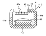
- FIG. 4 is a sectional view taken along line II-II in FIG. 3.
- It is sectional drawing which shows the modification of the terminal metal fitting shown by FIG. It is sectional drawing which shows the other modification of the terminal metal fitting shown by FIG.
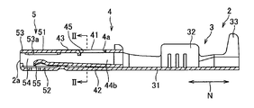
- the connector 1 constitutes a wire harness routed in an automobile or the like. As shown in FIG. 1, the connector 1 accommodates a terminal fitting 2 attached to a terminal of an electric wire 7 constituting the wire harness, and the terminal fitting 2. And a housing 6 provided with a terminal accommodating portion 61 to be provided.
- the terminal fitting 2 is obtained by bending a conductive sheet metal. As shown in FIGS. 2 to 4, the terminal fitting 2 is connected to a wire connecting portion 3 connected to the electric wire 7 and a lance 65 which is connected to the wire connecting portion 3 and which will be described later provided in the terminal accommodating portion 61. A housing mounting portion 4 to be locked and an electrical contact portion 5 connected to the other terminal fitting connected to the housing mounting portion 4 are provided. The terminal fitting 2 is inserted into the terminal accommodating portion 61 of the housing 6 from the electrical contact portion 5 side in a state where the wire connecting portion 3 is connected to the electric wire 7. The terminal fitting 2 is inserted into the terminal accommodating portion 61 along the longitudinal direction N thereof.
- the electric wire connecting portion 3 is erected from a base wall 31 for positioning the electric wire 7 on the surface and both ends of the base wall 31 in the width direction, and crimps the core wire 71 of the electric wire 7.
- a pair of core wire crimping pieces 32 and a pair of insulation coating crimping pieces 33 standing from both ends in the width direction of the base wall 31 and crimping the insulation coating of the electric wire 7 are provided.
- the electric wire connecting portion 3 has an end portion peeled off and the core wire 71 is exposed on the base wall 31 after the electric wire 7 having a round cross section is exposed on the base wall 31.
- the core wire crimping piece 32 is bent in the pressing direction, that is, the core wire 71 is caulked with the core wire crimping piece 32 to be electrically connected to the electric wire 7.
- the insulation coating crimping piece 33 is bent in a direction in which the coating portion of the electric wire 7 is pressed toward the base wall 31, that is, the insulation coating crimping piece 33 is caulked with the insulation coating crimping piece 33 and fixed to the electric wire 7. Is done. 2 and 3 show a state before the core wire crimping piece 32 and the insulation coating crimping piece 33 caulk the electric wire.
- the housing mounting portion 4 includes a base wall 42 that is continuous with the base wall 31, a first opposing wall 43 that is spaced from the base wall 42, a base wall 42, and Locked to a first cylinder portion 41 formed in a hollow prism shape by a pair of side walls 44 a and 44 b connecting both end portions in the width direction of the first opposing wall 43, and a lance 65 provided in the terminal accommodating portion 61. And a locking portion 45 to be provided. That is, the first opposing wall 43 constitutes the housing mounting portion 4.
- the housing attachment portion 4 is provided between the electric wire connection portion 3 and the electrical contact portion 5.
- the housing attachment portion 4 corresponds to a “tubular portion” indicated in the scope of claims.
- the first facing wall 43 corresponds to an “outer wall” indicated in the scope of the claims.
- the first tubular portion 41 is provided from the first opposing wall 43 to one side wall 44a of the pair of side walls 44a, 44b, and an opening that penetrates through the first opposing wall 43 and the one side wall 44a. 4a is provided.
- the locking portion 45 is formed by bending a part of the first facing wall 43 toward the inner side of the first tube portion 41. That is, the locking portion 45 is provided so as to protrude inward of the first tube portion 41 from the edge portion of the opening portion 4a on the electric contact portion 5 side.
- a plurality of convex portions 45 a are formed on the surface of the locking portion 45 on the side of the wire connecting portion 3. That is, a plurality of convex portions 45 a are formed on the surface of the locking portion 45 on the side of the electric wire connection portion 3, and the surface of the locking portion 45 is formed to be uneven.
- the convex portion 45a is formed in a hemispherical shape.
- the electrical contact portion 5 includes a base wall 52 continuous with the base wall 42, a second opposing wall 53 continuous with the first opposing wall 43 of the housing attachment portion 4, and a pair of side walls 44 a and 44 b provided on the housing attachment portion 4.
- a pair of side walls 54 connected to each other, a second cylindrical portion 51 formed in a hollow prism shape, and a spring piece 55 are provided.
- the second cylindrical portion 51 is provided with an insertion port at an end portion away from the housing mounting portion 4, that is, one end portion 2a (shown in FIG. 3) of the terminal fitting 2, and the insertion piece of the other terminal fitting from the insertion port. Is inserted.
- a projecting portion 53 a that projects from the inner surface of the second opposing wall toward the base wall 52 is provided on the inner surface of the second opposing wall 53 of the second cylindrical portion 51. The projecting portion 53 a extends along the longitudinal direction N.
- the spring piece 55 is attached to the inner surface of the base wall 52 that forms the second cylindrical portion 51.
- the spring piece 55 urges the inserter inserted inside the second cylindrical portion 51 toward the second opposing wall 53.
- the mating terminal fitting inserter when the mating terminal fitting inserter is inserted into the electrical contact portion 5, it is elastically brought into contact with the protruding portion 53 a and the spring piece 55. Thus, the mating terminal fitting and the terminal fitting 2 are electrically connected.
- the housing 6 is made of an insulating synthetic resin.
- the housing 6 includes a plurality of terminal accommodating portions 61 that accommodate the terminal fitting 2 and a lance 65 inside. In FIG. 1, only one of the plurality of terminal accommodating portions 61 is shown, and the other terminal accommodating portions 61 are omitted.
- the terminal accommodating portion 61 includes a bottom wall 62, a ceiling wall 63 provided at a distance from the bottom wall 62, and a pair of side walls that connect both edges in the width direction of the bottom wall 62 and the ceiling wall 63.
- 64 is formed in a cylindrical shape extending along the longitudinal direction N. That is, both end portions 6 a and 6 b along the longitudinal direction N of the terminal accommodating portion 61 communicate with the outside of the housing 6.
- the terminal fitting 2 described above is inserted into such a terminal accommodating portion 61 from the one end portion 6a along the longitudinal direction N toward the other end portion 6b.
- the lance 65 is formed in a rod shape.
- the lance 65 is provided at the center in the longitudinal direction N of the terminal accommodating portion 61.
- One end of the lance 65 in the longitudinal direction N is connected to the inner surface of the bottom wall 62, and the other end is a free end.
- the lance 65 is inclined in the direction from the bottom wall 62 to the ceiling wall 63 as it goes from one end to the other end. That is, the other end (free end) of the lance 65 extends toward the housing mounting portion 4 of the terminal fitting 2.
- the lance 65 is provided at the other end and is provided on the bottom wall 62 side of the contact portion 66 that contacts the locking portion 45 of the terminal fitting 2.
- a mouth opening portion 67 protruding from one end portion 6a of the terminal accommodating portion 61 is provided.
- the mouth opening portion 67 extends along the outer surface of the second opposing wall 53 constituting the electrical contact portion 5.
- the contact of the contact portion 66 of the lance 65 with the locking portion 45 of the terminal fitting 2 is expressed as “the terminal fitting 2 (locking portion 45) is locked with the lance 65”.
- the electric contact portion 5 side of the terminal fitting 2 connected to the terminal of the electric wire 7 is brought close to the terminal accommodating portion 61, and the terminal fitting 2 is inserted into the terminal accommodating portion 61 from the one end portion 6a.
- the electrical contact portion 5 presses the lance 65 in a direction approaching the bottom wall 62. In this way, the electrical contact portion 5 passes while elastically deforming the lance 65 in a direction approaching the bottom wall 62.
- the terminal fitting 2 is inserted into the terminal accommodating portion 61 and the electrical contact portion 5 is positioned at the other end 6b of the terminal accommodating portion 61, that is, when the terminal fitting 2 is accommodated in the terminal accommodating portion 61, it is elastic.
- the deformed lance 65 is restored to its original position, and the contact portion 66 of the lance 65 contacts the locking portion 45. That is, the terminal fitting 2 (locking portion 45) is locked to the lance 65. This prevents the terminal fitting 2 from coming out of the terminal accommodating portion 61.
- the connector is assembled.
- the locking portion 45 is provided so as to protrude from the edge of the opening 4a toward the inside of the housing mounting portion 4, so that the contact area of the locking portion 45 with respect to the lance 65 is increased.
- the holding force of the lance 65 with respect to the terminal fitting 2 can be improved. Therefore, it is possible to provide the connector 1 that can improve the holding force of the lance 65 provided in the terminal accommodating portion 61 with respect to the terminal fitting 2.
- locking part 45 is formed because a part of 1st opposing wall 41 which comprises the housing attachment part 4 is bent inside the housing attachment part 4, in order to form the terminal metal fitting 2. Therefore, the time required for manufacturing the connector 1 can be shortened, and the production efficiency can be improved.
- the surface of the locking portion 45 is uneven, the frictional resistance of the surface of the locking portion 45 is increased, and the locking portion 45 is less likely to slip with respect to the free end of the lance 65, further. It is possible to improve the holding force of the lance 65 provided in the terminal accommodating portion 61 with respect to the terminal fitting 2.
- the locking portion 45 has a convex portion 45 a formed on the surface on the wire connecting portion 3 side in a hemispherical shape. That is, the convex portion 45a is formed in a circular shape in plan view, but the present invention is not limited to this, and as shown in FIG. 5, the locking portion 45 'is formed on the surface on the electric wire connecting portion 3 side.
- the formed convex portion 45a ′ may be formed in a rectangular shape. That is, the protrusion 45a ′ may be formed in a rectangular shape in plan view as long as the engaging part 45 ′ has an unevenness on the surface on the wire connection part 3 side.
- the convex portion 45a and the convex portion 45a ′ are formed on the surface of the locking portion 45 and the locking portion 45 ′ on the wire connecting portion 3 side, but the present invention is limited to this.
- the convex portions 45a and the convex portions 45a ′ may not be provided.
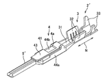
- the electrical contact portion 5 includes the second cylindrical portion 51 and the spring piece 55 and is the female terminal fitting 2 formed in a hollow prism shape, but the present invention is not limited thereto.
- the electrical contact portion 5 ′ may be an insert provided on the male terminal fitting 2 ′.
- FIG. 6 the same parts as those of the above-described embodiment are denoted by the same reference numerals and description thereof is omitted.
Landscapes
- Connector Housings Or Holding Contact Members (AREA)
- Details Of Connecting Devices For Male And Female Coupling (AREA)
Abstract
Priority Applications (4)
| Application Number | Priority Date | Filing Date | Title |
|---|---|---|---|
| CN2012800123759A CN103460512A (zh) | 2011-03-08 | 2012-03-05 | 连接器 |
| US14/002,300 US20130337704A1 (en) | 2011-03-08 | 2012-03-05 | Connector |
| KR1020137023971A KR20130143637A (ko) | 2011-03-08 | 2012-03-05 | 커넥터 |
| DE112012001119T DE112012001119T5 (de) | 2011-03-08 | 2012-03-05 | Verbinder |
Applications Claiming Priority (2)
| Application Number | Priority Date | Filing Date | Title |
|---|---|---|---|
| JP2011-050089 | 2011-03-08 | ||
| JP2011050089A JP2012186115A (ja) | 2011-03-08 | 2011-03-08 | コネクタ |
Publications (1)
| Publication Number | Publication Date |
|---|---|
| WO2012121186A1 true WO2012121186A1 (fr) | 2012-09-13 |
Family
ID=46798148
Family Applications (1)
| Application Number | Title | Priority Date | Filing Date |
|---|---|---|---|
| PCT/JP2012/055509 Ceased WO2012121186A1 (fr) | 2011-03-08 | 2012-03-05 | Connecteur |
Country Status (6)
| Country | Link |
|---|---|
| US (1) | US20130337704A1 (fr) |
| JP (1) | JP2012186115A (fr) |
| KR (1) | KR20130143637A (fr) |
| CN (1) | CN103460512A (fr) |
| DE (1) | DE112012001119T5 (fr) |
| WO (1) | WO2012121186A1 (fr) |
Families Citing this family (3)
| Publication number | Priority date | Publication date | Assignee | Title |
|---|---|---|---|---|
| JP6141612B2 (ja) * | 2012-09-21 | 2017-06-07 | 矢崎総業株式会社 | コネクタ |
| JP6342708B2 (ja) * | 2014-05-15 | 2018-06-13 | 矢崎総業株式会社 | コネクタと端子金具の接続構造 |
| JP7259444B2 (ja) * | 2019-03-20 | 2023-04-18 | 住友電装株式会社 | コネクタ |
Citations (4)
| Publication number | Priority date | Publication date | Assignee | Title |
|---|---|---|---|---|
| JPS61153975U (fr) * | 1985-03-18 | 1986-09-24 | ||
| JPH0719964U (ja) * | 1993-09-16 | 1995-04-07 | 住友電装株式会社 | コネクタ |
| JPH09213398A (ja) * | 1995-11-28 | 1997-08-15 | Yazaki Corp | コネクタハウジング構造 |
| JP2000348806A (ja) * | 1999-06-07 | 2000-12-15 | Sumitomo Wiring Syst Ltd | 端子金具 |
Family Cites Families (18)
| Publication number | Priority date | Publication date | Assignee | Title |
|---|---|---|---|---|
| JPH0310486U (fr) * | 1989-06-16 | 1991-01-31 | ||
| JPH0310485U (fr) * | 1989-06-16 | 1991-01-31 | ||
| JP2001217013A (ja) * | 2000-02-02 | 2001-08-10 | Sumitomo Wiring Syst Ltd | 端子金具 |
| JP2004047227A (ja) | 2002-07-10 | 2004-02-12 | Sumitomo Wiring Syst Ltd | 端子金具 |
| JP4500254B2 (ja) * | 2005-12-26 | 2010-07-14 | 矢崎総業株式会社 | フラット回路体 |
| US7252564B1 (en) * | 2006-01-27 | 2007-08-07 | Delphi Technologies, Inc. | Female electrical connector having crimping portions of double thickness |
| US7976353B2 (en) * | 2006-09-29 | 2011-07-12 | Tyco Electronics Corporation | Two-piece electrical terminal |
| US7530859B2 (en) * | 2007-05-08 | 2009-05-12 | Tyco Electronics Corporation | Electrical contact |
| JP5059481B2 (ja) * | 2007-05-08 | 2012-10-24 | 株式会社オートネットワーク技術研究所 | シールドコネクタ |
| DE102007040937B3 (de) * | 2007-08-30 | 2009-01-15 | Tyco Electronics Amp Gmbh | Elektrischer Kontakt |
| EP2151892B1 (fr) * | 2008-08-07 | 2017-05-03 | Sumitomo Wiring Systems, Ltd. | Contact et méthode de connexion associée. |
| JP5472679B2 (ja) * | 2009-04-07 | 2014-04-16 | 住友電装株式会社 | コネクタ |
| JP5233822B2 (ja) * | 2009-04-24 | 2013-07-10 | 住友電装株式会社 | 端子金具 |
| US20110014825A1 (en) * | 2009-07-16 | 2011-01-20 | Delphi Technologies, Inc. | Electrical terminal connection with galvanic sacrificial metal |
| JP2012199190A (ja) * | 2011-03-23 | 2012-10-18 | Yazaki Corp | コネクタ |
| JP5700811B2 (ja) * | 2011-03-30 | 2015-04-15 | 矢崎総業株式会社 | コネクタ |
| JP6092500B2 (ja) * | 2011-03-30 | 2017-03-08 | 矢崎総業株式会社 | コネクタ |
| JP5699029B2 (ja) * | 2011-04-28 | 2015-04-08 | 日本航空電子工業株式会社 | コネクタ |
-
2011
- 2011-03-08 JP JP2011050089A patent/JP2012186115A/ja active Pending
-
2012
- 2012-03-05 DE DE112012001119T patent/DE112012001119T5/de not_active Withdrawn
- 2012-03-05 CN CN2012800123759A patent/CN103460512A/zh active Pending
- 2012-03-05 WO PCT/JP2012/055509 patent/WO2012121186A1/fr not_active Ceased
- 2012-03-05 US US14/002,300 patent/US20130337704A1/en not_active Abandoned
- 2012-03-05 KR KR1020137023971A patent/KR20130143637A/ko not_active Ceased
Patent Citations (4)
| Publication number | Priority date | Publication date | Assignee | Title |
|---|---|---|---|---|
| JPS61153975U (fr) * | 1985-03-18 | 1986-09-24 | ||
| JPH0719964U (ja) * | 1993-09-16 | 1995-04-07 | 住友電装株式会社 | コネクタ |
| JPH09213398A (ja) * | 1995-11-28 | 1997-08-15 | Yazaki Corp | コネクタハウジング構造 |
| JP2000348806A (ja) * | 1999-06-07 | 2000-12-15 | Sumitomo Wiring Syst Ltd | 端子金具 |
Also Published As
| Publication number | Publication date |
|---|---|
| US20130337704A1 (en) | 2013-12-19 |
| DE112012001119T5 (de) | 2013-12-24 |
| KR20130143637A (ko) | 2013-12-31 |
| CN103460512A (zh) | 2013-12-18 |
| JP2012186115A (ja) | 2012-09-27 |
Similar Documents
| Publication | Publication Date | Title |
|---|---|---|
| US7465199B2 (en) | Female terminal | |
| CN109119785B (zh) | 电源连接器 | |
| JP5285985B2 (ja) | 雌型端子金具 | |
| JP5339154B2 (ja) | シールドコネクタ | |
| JP4958684B2 (ja) | コネクタ | |
| JP2010049896A (ja) | コネクタ | |
| JP2018200765A (ja) | コネクタ | |
| JP7139929B2 (ja) | ハーネス部品 | |
| JP2012209222A (ja) | 接続端子 | |
| WO2012121186A1 (fr) | Connecteur | |
| JP2015156387A (ja) | コネクタ | |
| KR20190108070A (ko) | 연결 단자 | |
| JP2020102305A (ja) | コネクタ | |
| JP7215933B2 (ja) | 接続端子 | |
| JP4446477B2 (ja) | コネクタ | |
| JP2008282705A (ja) | コネクタ | |
| WO2020121925A1 (fr) | Composant de faisceau | |
| JP4597750B2 (ja) | 雌型の端子金具及びコネクタ | |
| JPH0735313Y2 (ja) | コネクタ | |
| JP4881411B2 (ja) | 接続端子 | |
| CN111509448B (zh) | 接头连接器 | |
| KR200442917Y1 (ko) | 수직형 터미널조립체 | |
| AU2004200421A1 (en) | Connector | |
| JP2008047417A (ja) | 電気コネクター用端子及び該端子をそなえた電気コネクター | |
| KR100922154B1 (ko) | 커넥터 |
Legal Events
| Date | Code | Title | Description |
|---|---|---|---|
| 121 | Ep: the epo has been informed by wipo that ep was designated in this application |
Ref document number: 12754346 Country of ref document: EP Kind code of ref document: A1 |
|
| WWE | Wipo information: entry into national phase |
Ref document number: 14002300 Country of ref document: US |
|
| WWE | Wipo information: entry into national phase |
Ref document number: 112012001119 Country of ref document: DE Ref document number: 1120120011198 Country of ref document: DE |
|
| ENP | Entry into the national phase |
Ref document number: 20137023971 Country of ref document: KR Kind code of ref document: A |
|
| 122 | Ep: pct application non-entry in european phase |
Ref document number: 12754346 Country of ref document: EP Kind code of ref document: A1 |