WO2012124335A1 - Protecteur pour fibre optique et structure protectrice - Google Patents
Protecteur pour fibre optique et structure protectrice Download PDFInfo
- Publication number
- WO2012124335A1 WO2012124335A1 PCT/JP2012/001808 JP2012001808W WO2012124335A1 WO 2012124335 A1 WO2012124335 A1 WO 2012124335A1 JP 2012001808 W JP2012001808 W JP 2012001808W WO 2012124335 A1 WO2012124335 A1 WO 2012124335A1
- Authority
- WO
- WIPO (PCT)
- Prior art keywords
- ferrule
- optical fiber
- protector
- main body
- fiber
- Prior art date
- Legal status (The legal status is an assumption and is not a legal conclusion. Google has not performed a legal analysis and makes no representation as to the accuracy of the status listed.)
- Ceased
Links
Images


Classifications
-
- G—PHYSICS
- G02—OPTICS
- G02B—OPTICAL ELEMENTS, SYSTEMS OR APPARATUS
- G02B6/00—Light guides; Structural details of arrangements comprising light guides and other optical elements, e.g. couplings
- G02B6/24—Coupling light guides
- G02B6/36—Mechanical coupling means
- G02B6/38—Mechanical coupling means having fibre to fibre mating means
- G02B6/3807—Dismountable connectors, i.e. comprising plugs
- G02B6/3887—Anchoring optical cables to connector housings, e.g. strain relief features
- G02B6/38875—Protection from bending or twisting
-
- G—PHYSICS
- G02—OPTICS
- G02B—OPTICAL ELEMENTS, SYSTEMS OR APPARATUS
- G02B6/00—Light guides; Structural details of arrangements comprising light guides and other optical elements, e.g. couplings
- G02B6/44—Mechanical structures for providing tensile strength and external protection for fibres, e.g. optical transmission cables
- G02B6/4439—Auxiliary devices
- G02B6/4471—Terminating devices ; Cable clamps
- G02B6/4478—Bending relief means
Definitions
- the present invention relates to a protector for optical fiber to be used to protect an optical fiber and a protective structure for optical fiber using the same.
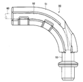
- Patent documents 1 to 3 There have been proposed various protectors for optical fibers each of which is used to protect an optical fiber. There are many cases where a protector for optical fiber is arranged in the vicinity of an optical connector or the like. In this situation, a protector for optical fiber with ferrule has been proposed (see Patent document1). A conventional example of the protector for optical fiber with ferrule is shown in FIGS. 1A and 1B.
- a protector for optical fiber 50 includes a protector main body 51 having a fiber receiving passage 52, and a ferrule 53 integrally mounted to the protector main body 51. A portion of an optical fiber 60 is received in the fiber receiving passage 52 in a curved shape. An end of the optical fiber 60 is connected to the ferrule 53.
- the optical fiber 60 is mounted in the protector for optical fiber 50 by connecting the end of the optical fiber 60 to the ferrule 53 by laser welding or the like and then receiving the optical fiber 60 in the fiber receiving passage 52. Since the ferrule 53 is integrally mounted to the protector main body 51, there is an advantage that it is not necessary to adjust a position of the ferrule 53 with respect to the protector main body 51 such that they have a certain positional relation.
- the protector for optical fiber 50 however has the following problem.
- the ferrule 53 is an important portion of the protector for optical fiber 50 where an optical connection is carried out, which requires a high accuracy of dimension. This needs to produce the protector main body 51 in accordance with the accuracy of dimension of the ferrule 53. As the result, the protector for optical fiber 50 is a high price product as a whole.
- the ferrule 53 is further required to have characteristics suitable for a connection means (e.g., laser welding) to be used to connect the ferrule 53 to the optical fiber 60.
- a connection means e.g., laser welding
- the protector main body 51 is required to have strength sufficient to resist reaction force from the optical fiber 60.
- the required material characteristics of the ferrule 53 differ from the required material characteristics of the protector main body 51.
- the production cost of the protector for optical fiber 50 is reduced as a whole. This however needs to adjust a position of the ferrule 53 with respect to the protector for optical fiber 50 such that they have a certain positional relation, which brings a new problem that the ferrule 53 is not easily mounted to the protector for optical fiber 50 in the certain positional relation.
- an object of the present invention is to provide a protector for optical fiber in which a ferrule and the protector for optical fiber are separated members and the ferrule is easily mounted to the protector for optical fiber in a certain positional relation, and a protective structure for optical fiber using the same.
- the present invention provides a protector for optical fiber comprising: a protector main body that includes a fiber receiving passage receiving an optical fiber; and a ferrule holding portion that is integrally mounted to the protector main body and holds a ferrule.
- the ferrule to be held in the ferrule holding portion includes a ferrule main body and a flange that protrudes from the ferrule main body, and the ferrule holding portion includes a main body receiving groove that receives the ferrule main body and a flange receiving groove that receives the flange.
- the protector main body includes a fiber drop-off preventing portion that prevents the optical fiber from dropping-off the fiber receiving passage.
- the fiber receiving passage is defined by an inner circumference side bending side wall, an outer circumference side bending side wall and a bottom surface wall, and a reinforcing portion is installed to at least one of the inner circumference side bending side wall and the outer circumference side bending side wall.
- the reinforcing portion is installed to a bending side wall on which the fiber drop-off preventing portion is installed, from among the inner circumference side bending side wall and the outer circumference side bending side wall.
- the reinforcing portion reinforces the ferrule holding portion and the at least one of the inner circumference side bending side wall and the outer circumference side bending side wall.
- a protrusion for fiber direction correction is installed on a distal end of the outer circumference side bending side wall to protrude toward the fiber receiving passage.
- the present invention provides a protective structure for optical fiber comprising: a ferrule comprising: a ferrule main body; and a flange that protrudes from the ferrule main body, and a protector for optical fiber comprising: a protector main body that includes a fiber receiving passage; and a ferrule holding portion that includes a main body receiving groove and a flange receiving groove and is integrally mounted to the protector main body, wherein an optical fiber is received in the fiber receiving passage, the ferrule main body is received in the main body receiving groove, and the flange is received in the flange receiving groove.
- the ferrule when a ferrule is held in the ferrule holding portion, the ferrule is mounted to the protector for optical fiber in a certain positional relation. Therefore, the ferrule is easily mounted to the protector for optical fiber in the certain positional relation.
- FIG. 1A is a plan view of a conventional protector for optical fiber.
- FIG. 1B is a back view of the conventional protector for optical fiber.
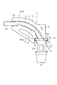
- FIG. 2 is a plane view of a protector for optical fiber according to an exemplary embodiment of the present invention.
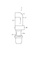
- FIG. 3 is a right side view of the protector for optical fiber according to the exemplary embodiment of the present invention.
- FIG. 4 is a back view of the protector for optical fiber according to the exemplary embodiment of the present invention.
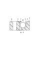
- FIG. 5 is a cross-section view of the protector for optical fiber along the line A-A in FIG. 2.
- FIGS. 2 to 5 illustrate the exemplary embodiment of the present invention.
- a protector for optical fiber 1 is made of a synthetic resin, for example.
- the protector for optical fiber 1 includes a protector main body 2 that receives an optical fiber 20 along a certain routing path and protects it, and a ferrule holding portion 10 that is integrally mounted to the protector main body 2 and holds a ferrule 21 connected to an end of the optical fiber 20.
- the protector main body 2 includes a fiber receiving passage 3.
- the fiber receiving passage 3 is curved such that a direction of the optical fiber 20 at one end of the fiber receiving passage 3 intersects with a direction of the optical fiber 20 at the other end of the fiber receiving passage 3 at a 90-degree angle.
- the fiber receiving passage 3 is defined by an inner circumference side bending side wall 4, an outer circumference side bending side wall 5 and a bottom surface wall 6 (see FIG. 5), and opens at a top surface side thereof.
- two engagement protrusions 7 and 7 each of which is a fiber drop-off preventing portion are installed in a protruding manner on the inner circumference side bending side wall 4 at a suitable interval.
- a protrusion dimension of each engagement protrusion 7 is set to a dimension that allows the optical fiber 20 to be received in the fiber receiving passage 3 by pushing the optical fiber 20 and prevents the optical fiber 20 received in the fiber receiving passage 3 from dropping off the fiber receiving passage 3 by itself.
- a reinforcing beam 8 which is a reinforcing portion is installed to the inner circumference side bending side wall 4.
- the reinforcing beam 8 links one end with the other end of the inner circumference side bending side wall 4.
- One end of the reinforcing beam 8 links to the ferrule holding portion 10.
- the reinforcing beam 8 is formed into a substantially straight beam shape.
- a reinforcing beam 9 which is a reinforcing portion is installed to the outer circumference side bending side wall 5.
- the reinforcing beam 9 is formed into an L-shape.
- a protrusion for fiber direction correction 5a which protrudes toward the fiber receiving passage 3 is installed on the outer circumference side bending side wall 5 at a distal end of the outer circumference side bending side wall 5.
- the ferrule holding portion 10 opens to one end of the fiber receiving passage 3 and has a ferrule holding groove 11 to be used to receive and hold the ferrule 21.
- the ferrule 21 includes a ferrule main body 21a and a flange 21b that protrudes laterally from the ferrule main body 21a.
- the ferrule holding groove 11 includes a main body receiving groove 11a that receives a portion of the ferrule main body 21a and a flange receiving groove 11b that receives the flange 21b.
- the end of the optical fiber 20 is connected to the ferrule 21 by laser welding or the like (process for connecting fiber to ferrule).
- the ferrule 21 is received in the ferrule holding groove 11 and the optical fiber 20 is received in the fiber receiving passage 3 while being bent (process for setting fiber and ferrule).
- the work is finished.
- the process for setting fiber and ferrule may be carried out before the process for connecting fiber to ferrule. More specifically, after the ferrule 21 is received in the ferrule holding groove 11 and the optical fiber 20 is received in the fiber receiving passage 3 while being bent, the end of the optical fiber 20 is connected to the ferrule 21 by laser welding or the like.
- the protector for optical fiber 1 includes the protector main body 2 that has the fiber receiving passage 3 receiving the optical fiber 20, and the ferrule holding portion 10 that is integrally mounted to the protector main body 2 and holds the ferrule 21. Therefore, since the ferrule 21 can be held in the ferrule holding portion 10 of the protector for optical fiber 1, the ferrule 21 is easily mounted to the protector for optical fiber 1 in a certain positional relation.
- the protector for optical fiber 1 and the ferrule 21 are separated members, materials suitable for respective required characteristics can be independently adopted as materials of the protector for optical fiber 1 and the ferrule 21. This realizes a low cost as a whole. Since the protector for optical fiber 1 and the ferrule 21 are independently produced according to a user request (e.g., configuration), the user request can be realized at a low cost as a whole.
- a user request e.g., configuration
- the ferrule 21 to be held in the ferrule holding portion 10 includes the ferrule main body 21a and the flange 21b that protrudes from the ferrule main body 21a.
- the ferrule holding portion 10 includes the main body receiving groove 11a that receives the ferrule main body 21a and the flange receiving groove 11b that receives the flange 21b. Therefore, even if bending reaction force acts on the ferrule 21, the ferrule 21 can be steadily held. More specifically, when reaction force acts on the ferrule 21 in a direction of arrow shown in FIG. 2, the reaction force is concentrated on the flange 21b of the ferrule 21 and a side surface of the flange receiving groove 11b. As the result, the reaction force is certainly received by these members.
- the protector main body 2 includes the engagement protrusions 7 and 7 that prevents the optical fiber 20 from dropping off the fiber receiving passage 3. This prevents the optical fiber 20 having been received in the fiber receiving passage 3 from dropping off the fiber receiving passage 3.
- the fiber receiving passage 3 is defined by the inner circumference side bending side wall 4, the outer circumference side bending side wall 5 and the bottom surface wall 6.
- the reinforcing beams 8 and 9 are respectively installed to the inner circumference side bending side wall 4 and the outer circumference side bending side wall 5. This certainly prevents the inner circumference side bending side wall 4 and the outer circumference side bending side wall 5 from being deformed or broken by bending reaction force from the optical fiber 20.
- either the reinforcing beams 8 or 9 may be omitted.
- the protector for optical fiber 1 is made by metal molding, if the engagement protrusions 7 and 7 are installed on the inner circumference side bending side wall 4, a clearance hole for engagement protrusion molding 6a is formed on the bottom surface wall 6 at a side of the inner circumference side bending side wall 4. This reduces strength of the inner circumference side bending side wall 4.
- the reinforcing beam 8 prevents the strength of bending side wall on which the engagement protrusions 7 and 7 are installed from being reduced.
- the reinforcing beam 8 links one end with the other end of the inner circumference side bending side wall 4, and one end of the reinforcing beam 8 links to the ferrule holding portion 10.
- the reinforcing beam 8 reinforces the inner circumference side bending side wall 4 and the ferrule holding portion 10.
- the reinforcing beam 8 increases the strength of the inner circumference side bending side wall 4 and strength of the ferrule holding portion 10. This certainly prevents the ferrule holding portion 10 from being deformed or broken by bending reaction force from the optical fiber 20.
- the protrusion for fiber direction correction 5a which protrudes toward the fiber receiving passage 3 is installed on the outer circumference side bending side wall 5 at the distal end of the outer circumference side bending side wall 5. This allows the optical fiber 20 to be drawn from the fiber receiving passage 3 toward a desired direction certainly.
- a width dimension of the fiber receiving passage 3 is generally set to be slightly smaller than one of the optical fiber 20. Under this configuration, the optical fiber 20 is drawn from the fiber receiving passage 3 toward a direction where bentness of the optical fiber 20 is reduced (toward a side of the outer circumference side bending side wall 5 with respect to the desired direction), due to bending restoring force corresponding to the difference between the width dimensions.
- the protrusion for fiber direction correction 5a can correct the wrong direction.
Landscapes
- Physics & Mathematics (AREA)
- General Physics & Mathematics (AREA)
- Optics & Photonics (AREA)
- Mechanical Coupling Of Light Guides (AREA)
- Light Guides In General And Applications Therefor (AREA)
Abstract
L'invention porte sur un protecteur (1) pour une fibre optique (20), lequel protecteur comprend un corps principal de protecteur (2) et la partie de maintien de virole (10). Le corps principal de protecteur (2) comprend un passage de réception de fibre (3) recevant une fibre optique (20). La partie de support de virole (10) est montée de façon intégrée sur le corps principal de protecteur (2) et supporte une virole (21).
Priority Applications (2)
| Application Number | Priority Date | Filing Date | Title |
|---|---|---|---|
| CN201280013624.6A CN103443678B (zh) | 2011-03-16 | 2012-03-15 | 光纤保护器和保护结构 |
| EP12716674.2A EP2686723B1 (fr) | 2011-03-16 | 2012-03-15 | Protecteur pour fibre optique et structure protectrice |
Applications Claiming Priority (2)
| Application Number | Priority Date | Filing Date | Title |
|---|---|---|---|
| JP2011058081A JP5939738B2 (ja) | 2011-03-16 | 2011-03-16 | 光ファイバ用プロテクタ及び光ファイバ用プロテクト構造 |
| JP2011-058081 | 2011-03-16 |
Publications (1)
| Publication Number | Publication Date |
|---|---|
| WO2012124335A1 true WO2012124335A1 (fr) | 2012-09-20 |
Family
ID=46001673
Family Applications (1)
| Application Number | Title | Priority Date | Filing Date |
|---|---|---|---|
| PCT/JP2012/001808 Ceased WO2012124335A1 (fr) | 2011-03-16 | 2012-03-15 | Protecteur pour fibre optique et structure protectrice |
Country Status (4)
| Country | Link |
|---|---|
| EP (1) | EP2686723B1 (fr) |
| JP (1) | JP5939738B2 (fr) |
| CN (1) | CN103443678B (fr) |
| WO (1) | WO2012124335A1 (fr) |
Cited By (2)
| Publication number | Priority date | Publication date | Assignee | Title |
|---|---|---|---|---|
| WO2014100215A1 (fr) * | 2012-12-21 | 2014-06-26 | David Welford | Protecteur de fibre optique |
| US10166633B2 (en) | 2013-12-12 | 2019-01-01 | Messer Cutting Systems Gmbh | Laser beam machine for thermally treating workpieces with a cable guidance system having a fitted deflection unit |
Families Citing this family (2)
| Publication number | Priority date | Publication date | Assignee | Title |
|---|---|---|---|---|
| JP6272649B2 (ja) * | 2013-02-15 | 2018-01-31 | 矢崎総業株式会社 | 光コネクタ |
| CN106291827A (zh) * | 2015-06-29 | 2017-01-04 | 天津市华诚致通科技有限公司 | 一种多功能光纤连接器 |
Citations (8)
| Publication number | Priority date | Publication date | Assignee | Title |
|---|---|---|---|---|
| EP0213672A2 (fr) * | 1985-08-16 | 1987-03-11 | Augat Inc. | Connecteur pour câble multifibre optique |
| US5157749A (en) * | 1984-06-08 | 1992-10-20 | Amp Incorporated | High precision optical fiber connectors |
| EP0803750A1 (fr) * | 1996-04-23 | 1997-10-29 | Lucent Technologies Inc. | Connecteur à fibre optique avec embout immobile |
| EP1074868A1 (fr) * | 1999-08-05 | 2001-02-07 | Yazaki Corporation | Connecteur optique |
| JP2001249253A (ja) | 1999-12-27 | 2001-09-14 | Yazaki Corp | 光リングネットワーク、光コネクタ、及びハイブリッドコネクタ |
| US20010043775A1 (en) * | 2000-04-21 | 2001-11-22 | Yazaki Corporation | Optical ring network, optical connector, and hybrid connector |
| JP2003149504A (ja) | 2001-11-14 | 2003-05-21 | Auto Network Gijutsu Kenkyusho:Kk | 光コネクタ |
| JP2008043056A (ja) | 2006-08-07 | 2008-02-21 | Mitsubishi Electric System & Service Co Ltd | ケーブルガイド |
Family Cites Families (1)
| Publication number | Priority date | Publication date | Assignee | Title |
|---|---|---|---|---|
| GB2357857B (en) * | 1999-12-27 | 2003-06-18 | Yazaki Corp | Connector having pivotably accommodated optic fibre ferrule |
-
2011
- 2011-03-16 JP JP2011058081A patent/JP5939738B2/ja active Active
-
2012
- 2012-03-15 EP EP12716674.2A patent/EP2686723B1/fr not_active Not-in-force
- 2012-03-15 WO PCT/JP2012/001808 patent/WO2012124335A1/fr not_active Ceased
- 2012-03-15 CN CN201280013624.6A patent/CN103443678B/zh not_active Expired - Fee Related
Patent Citations (8)
| Publication number | Priority date | Publication date | Assignee | Title |
|---|---|---|---|---|
| US5157749A (en) * | 1984-06-08 | 1992-10-20 | Amp Incorporated | High precision optical fiber connectors |
| EP0213672A2 (fr) * | 1985-08-16 | 1987-03-11 | Augat Inc. | Connecteur pour câble multifibre optique |
| EP0803750A1 (fr) * | 1996-04-23 | 1997-10-29 | Lucent Technologies Inc. | Connecteur à fibre optique avec embout immobile |
| EP1074868A1 (fr) * | 1999-08-05 | 2001-02-07 | Yazaki Corporation | Connecteur optique |
| JP2001249253A (ja) | 1999-12-27 | 2001-09-14 | Yazaki Corp | 光リングネットワーク、光コネクタ、及びハイブリッドコネクタ |
| US20010043775A1 (en) * | 2000-04-21 | 2001-11-22 | Yazaki Corporation | Optical ring network, optical connector, and hybrid connector |
| JP2003149504A (ja) | 2001-11-14 | 2003-05-21 | Auto Network Gijutsu Kenkyusho:Kk | 光コネクタ |
| JP2008043056A (ja) | 2006-08-07 | 2008-02-21 | Mitsubishi Electric System & Service Co Ltd | ケーブルガイド |
Cited By (2)
| Publication number | Priority date | Publication date | Assignee | Title |
|---|---|---|---|---|
| WO2014100215A1 (fr) * | 2012-12-21 | 2014-06-26 | David Welford | Protecteur de fibre optique |
| US10166633B2 (en) | 2013-12-12 | 2019-01-01 | Messer Cutting Systems Gmbh | Laser beam machine for thermally treating workpieces with a cable guidance system having a fitted deflection unit |
Also Published As
| Publication number | Publication date |
|---|---|
| JP2012194355A (ja) | 2012-10-11 |
| CN103443678B (zh) | 2015-08-26 |
| CN103443678A (zh) | 2013-12-11 |
| EP2686723A1 (fr) | 2014-01-22 |
| JP5939738B2 (ja) | 2016-06-22 |
| EP2686723B1 (fr) | 2016-09-21 |
Similar Documents
| Publication | Publication Date | Title |
|---|---|---|
| US9720183B2 (en) | Fiber optic adapter with enhanced alignment | |
| US20130101258A1 (en) | Optical connector | |
| EP2686723B1 (fr) | Protecteur pour fibre optique et structure protectrice | |
| JP2012128341A (ja) | 二芯型光コネクタ | |
| CN111130030B (zh) | 连结件和线束 | |
| CN107210594A (zh) | 带夹 | |
| CN209526303U (zh) | 同轴连接器 | |
| US20160091668A1 (en) | Optical Connector | |
| WO2014132283A1 (fr) | Connecteur, ainsi que collecteur et prise utilisés chacun pour ledit connecteur | |
| JP2012194410A (ja) | 光コネクタ | |
| CN103154796B (zh) | 光连接器用套筒及光连接器 | |
| US20150016785A1 (en) | Optical connector, male connector housing for optical connector, and female connector housing for optical connector | |
| JP6992212B1 (ja) | フェルール用ピンクランプ、ガイドピン付きピンクランプ、及び光コネクタ | |
| JP7089679B2 (ja) | レバー式コネクタ | |
| US12151369B2 (en) | Separator plate and protection member for wire member | |
| US20160018607A1 (en) | Backlash prevention mechanism of adapter for optical connector | |
| JP5705790B2 (ja) | 光コネクタ及びコネクタ構造 | |
| JP5705791B2 (ja) | 光コネクタ及びコネクタ構造 | |
| JP2013008496A (ja) | 電線カバー | |
| KR20200022638A (ko) | 리셉터클 터미널 | |
| JP6346070B2 (ja) | 光コネクタ | |
| WO2014196538A1 (fr) | Connecteur optique | |
| JP2014145927A (ja) | 光接続部材、光接続構造 | |
| US11329417B2 (en) | Connector | |
| JP6408931B2 (ja) | カラーおよびそのカラーを備える車両用のサンバイザ |
Legal Events
| Date | Code | Title | Description |
|---|---|---|---|
| 121 | Ep: the epo has been informed by wipo that ep was designated in this application |
Ref document number: 12716674 Country of ref document: EP Kind code of ref document: A1 |
|
| NENP | Non-entry into the national phase |
Ref country code: DE |
|
| REEP | Request for entry into the european phase |
Ref document number: 2012716674 Country of ref document: EP |
|
| WWE | Wipo information: entry into national phase |
Ref document number: 2012716674 Country of ref document: EP |