WO2012124656A1 - Cellule solaire à dioxyde de silicium - Google Patents
Cellule solaire à dioxyde de silicium Download PDFInfo
- Publication number
- WO2012124656A1 WO2012124656A1 PCT/JP2012/056292 JP2012056292W WO2012124656A1 WO 2012124656 A1 WO2012124656 A1 WO 2012124656A1 JP 2012056292 W JP2012056292 W JP 2012056292W WO 2012124656 A1 WO2012124656 A1 WO 2012124656A1
- Authority
- WO
- WIPO (PCT)
- Prior art keywords
- dye
- solar cell
- silicon dioxide
- titanium dioxide
- porous titanium
- Prior art date
- Legal status (The legal status is an assumption and is not a legal conclusion. Google has not performed a legal analysis and makes no representation as to the accuracy of the status listed.)
- Ceased
Links
Images


Classifications
-
- H—ELECTRICITY
- H01—ELECTRIC ELEMENTS
- H01G—CAPACITORS; CAPACITORS, RECTIFIERS, DETECTORS, SWITCHING DEVICES, LIGHT-SENSITIVE OR TEMPERATURE-SENSITIVE DEVICES OF THE ELECTROLYTIC TYPE
- H01G9/00—Electrolytic capacitors, rectifiers, detectors, switching devices, light-sensitive or temperature-sensitive devices; Processes of their manufacture
- H01G9/20—Light-sensitive devices
- H01G9/2004—Light-sensitive devices characterised by the electrolyte, e.g. comprising an organic electrolyte
- H01G9/2018—Light-sensitive devices characterised by the electrolyte, e.g. comprising an organic electrolyte characterised by the ionic charge transport species, e.g. redox shuttles
-
- H—ELECTRICITY
- H01—ELECTRIC ELEMENTS
- H01G—CAPACITORS; CAPACITORS, RECTIFIERS, DETECTORS, SWITCHING DEVICES, LIGHT-SENSITIVE OR TEMPERATURE-SENSITIVE DEVICES OF THE ELECTROLYTIC TYPE
- H01G9/00—Electrolytic capacitors, rectifiers, detectors, switching devices, light-sensitive or temperature-sensitive devices; Processes of their manufacture
- H01G9/20—Light-sensitive devices
- H01G9/2004—Light-sensitive devices characterised by the electrolyte, e.g. comprising an organic electrolyte
-
- H—ELECTRICITY
- H01—ELECTRIC ELEMENTS
- H01G—CAPACITORS; CAPACITORS, RECTIFIERS, DETECTORS, SWITCHING DEVICES, LIGHT-SENSITIVE OR TEMPERATURE-SENSITIVE DEVICES OF THE ELECTROLYTIC TYPE
- H01G9/00—Electrolytic capacitors, rectifiers, detectors, switching devices, light-sensitive or temperature-sensitive devices; Processes of their manufacture
- H01G9/20—Light-sensitive devices
- H01G9/2027—Light-sensitive devices comprising an oxide semiconductor electrode
- H01G9/2031—Light-sensitive devices comprising an oxide semiconductor electrode comprising titanium oxide, e.g. TiO2
-
- H—ELECTRICITY
- H01—ELECTRIC ELEMENTS
- H01G—CAPACITORS; CAPACITORS, RECTIFIERS, DETECTORS, SWITCHING DEVICES, LIGHT-SENSITIVE OR TEMPERATURE-SENSITIVE DEVICES OF THE ELECTROLYTIC TYPE
- H01G9/00—Electrolytic capacitors, rectifiers, detectors, switching devices, light-sensitive or temperature-sensitive devices; Processes of their manufacture
- H01G9/20—Light-sensitive devices
- H01G9/2059—Light-sensitive devices comprising an organic dye as the active light absorbing material, e.g. adsorbed on an electrode or dissolved in solution
-
- H—ELECTRICITY
- H01—ELECTRIC ELEMENTS
- H01G—CAPACITORS; CAPACITORS, RECTIFIERS, DETECTORS, SWITCHING DEVICES, LIGHT-SENSITIVE OR TEMPERATURE-SENSITIVE DEVICES OF THE ELECTROLYTIC TYPE
- H01G9/00—Electrolytic capacitors, rectifiers, detectors, switching devices, light-sensitive or temperature-sensitive devices; Processes of their manufacture
- H01G9/20—Light-sensitive devices
- H01G9/2068—Panels or arrays of photoelectrochemical cells, e.g. photovoltaic modules based on photoelectrochemical cells
- H01G9/2072—Panels or arrays of photoelectrochemical cells, e.g. photovoltaic modules based on photoelectrochemical cells comprising two or more photoelectrodes sensible to different parts of the solar spectrum, e.g. tandem cells
-
- H—ELECTRICITY
- H10—SEMICONDUCTOR DEVICES; ELECTRIC SOLID-STATE DEVICES NOT OTHERWISE PROVIDED FOR
- H10K—ORGANIC ELECTRIC SOLID-STATE DEVICES
- H10K2102/00—Constructional details relating to the organic devices covered by this subclass
- H10K2102/10—Transparent electrodes, e.g. using graphene
- H10K2102/101—Transparent electrodes, e.g. using graphene comprising transparent conductive oxides [TCO]
- H10K2102/102—Transparent electrodes, e.g. using graphene comprising transparent conductive oxides [TCO] comprising tin oxides, e.g. fluorine-doped SnO2
-
- Y—GENERAL TAGGING OF NEW TECHNOLOGICAL DEVELOPMENTS; GENERAL TAGGING OF CROSS-SECTIONAL TECHNOLOGIES SPANNING OVER SEVERAL SECTIONS OF THE IPC; TECHNICAL SUBJECTS COVERED BY FORMER USPC CROSS-REFERENCE ART COLLECTIONS [XRACs] AND DIGESTS
- Y02—TECHNOLOGIES OR APPLICATIONS FOR MITIGATION OR ADAPTATION AGAINST CLIMATE CHANGE
- Y02E—REDUCTION OF GREENHOUSE GAS [GHG] EMISSIONS, RELATED TO ENERGY GENERATION, TRANSMISSION OR DISTRIBUTION
- Y02E10/00—Energy generation through renewable energy sources
- Y02E10/50—Photovoltaic [PV] energy
- Y02E10/542—Dye sensitized solar cells
Definitions
- the present invention relates to a solar cell, and more particularly to a dye-sensitized silicon dioxide solar cell using titanium dioxide.
- a dry solar cell using a semiconductor such as silicon is in a practical stage.
- a semiconductor solar cell is high in conversion efficiency but expensive because it uses a high-purity material.
- As a relatively inexpensive solar cell there is a wet solar cell using titanium dioxide (TiO 2 ) and an electrolyte.
- the light that can be used for the electromotive force of titanium dioxide is only ultraviolet light having a wavelength of 380 nm or less.
- the ultraviolet light in this wavelength region is only 4% of sunlight, and the utilization efficiency of sunlight is actually 4% at maximum. Is 1% at most, so the utilization efficiency of sunlight as a solar cell is extremely low.
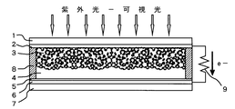
- FIG. 1 illustrates the basic configuration of a dye-sensitized solar cell.
- 1 is a glass substrate, and a transparent conductive film 2 such as FTO is formed on one surface.
- 3 is a porous titanium dioxide oxide sintered body, and a ruthenium complex dye is adsorbed on the surface of the pores.
- Reference numeral 4 denotes an electrolytic solution. Generally, an iodine electrolyte in which iodine is dissolved in an aqueous potassium iodide solution is used.
- Reference numeral 5 denotes a platinum counter electrode, which is formed on a glass substrate 7 on which a conductive film 6 such as FTO is formed.
- 8 is a sealing material
- 9 is an external load such as a resistor.
- the light incident through the FTO transparent conductive film 2 on the glass substrate 1 is absorbed by the ruthenium complex dye adsorbed on the pore surface of the porous titanium dioxide sintered body 3.
- the ruthenium complex dye that has absorbed the light changes from an electronic ground state to an excited state, and the electrons of the ruthenium complex dye in the excited state are injected into the porous titanium dioxide sintered body 3.
- the ruthenium complex dye is in an oxidized state.
- the porous titanium dioxide sintered body 3 in which the excitation energy level of the ruthenium complex dye is a semiconductor. Must be more negative than the conduction band energy level.
- Electrons injected into the porous titanium dioxide sintered body 3 are taken out of the transparent conductive film 2 by diffusion and guided to the platinum counter electrode 5 via the load 9.
- the oxidized ruthenium complex dye receives electrons from iodine in the iodine-related electrolyte 4 and returns to the ruthenium complex dye in the ground state.
- the solar light utilization efficiency of the dye-sensitized solar cell having such a configuration is theoretically 30%, but is actually 10% at the maximum.
- Titanium dioxide has a photocatalytic function.
- fused quartz treated with hydrohalic acid as a material having a photocatalytic function is disclosed in Japanese Patent Application Laid-Open Nos. 2004-290748 and 2004-290747. Yes.
- the artificial quartz photocatalyst functions as a photocatalyst in a wider wavelength region of 200 to 800 nm than the photocatalyst using fused silica as a raw material disclosed in JP-A-2004-290748 and JP-A-2004-290747.
- reference numerals 11 and 17 denote a 30 mm ⁇ 30 mm glass substrate on which a transparent conductive layer FTO (fluorine-doped tin oxide) layer 12 and an FTO layer 16 are formed, and the size of the solar cell is 20 mm ⁇ 20 mm.
- FTO fluorine-doped tin oxide
- n-type semiconductor layer 13 such as zinc oxide (ZnO) or titanium oxide (TiO 2 ) is formed on the light incident side FTO layer, and a platinum film is formed on the FTO layer 16 facing the light incident side FTO layer 12. 15 is formed.
- a solar cell material 20 in which a glass containing SiO 2 and an electrolyte are mixed with a thickness of 0.15 to 0.20 mm is enclosed.
- a material such as glass containing SiO 2 is immersed in a 5% hydrofluoric acid aqueous solution for 5 minutes, washed with water, dried, and pulverized so that the particle size becomes 0.2 mm or less. ing.
- the electrolyte is obtained by adding 0.1mol of LiI, and I 2 0.05 mol, a 4-tert-butylpyridine 0.5mol, tetrabutylammonium iodide in 0.5mol acetonitrile solvent.
- the silicon dioxide photovoltaic cell mechanism Details of the silicon dioxide photovoltaic cell mechanism are unknown, but it is absorbed when irradiated with sunlight having a wavelength of 200 to 800 nm, and electrons are transferred from the silicon dioxide side electrode to the counter electrode via the load. In other words, there is a phenomenon that current flows from the counter electrode toward the silicon dioxide side electrode.
- the short-circuit current and open-circuit voltage obtained by irradiating a fluorescent light of 15,000 to 19,000 lux are as follows. Artificial quartz: Short-circuit current 0.5 ⁇ A, release voltage 35mV Fused silica glass: Short-circuit current 0.5 ⁇ A, release voltage 30 mV Soda lime glass: short circuit current 0.3 ⁇ A, release voltage 15 mV Alkali-free glass: short-circuit current 0.4 ⁇ A, release voltage 30 mV Borosilicate glass: Short-circuit current 0.3 ⁇ A, release voltage 14 mV
- short-circuit current 0.1 ⁇ A release voltage 3 mV
- Fused silica glass Short-circuit current 0.2 ⁇ A
- Soda lime glass Short-circuit current 0.1 ⁇ A
- Alkali-free glass Short-circuit current 0.1 ⁇ A
- Borosilicate glass short-circuit current 0.2 ⁇ A, release voltage 12 mV
- An object of this invention is to obtain a solar cell that exhibits high light utilization efficiency.
- the inventors of the present invention have discovered that the artificial quartz grains, fused quartz grains, and glass grains treated with hydrohalic acid can be finely powdered to exhibit a further excellent solar cell function.
- the present inventors have discovered that artificial quartz grains or glass grains finely pulverized to near the wavelength of light have a solar cell material function.
- the inventors of the present invention have found that a silicon dioxide solar cell can generate electricity even by infrared light.
- the invention combines a silicon dioxide solar cell with a dye-sensitized titanium dioxide solar cell in a tandem configuration, an electrode on the silicon dioxide solar cell side, and a dye-sensitized titanium dioxide solar cell.
- a solar cell is obtained that generates electricity by light in all regions ranging from ultraviolet light to infrared light.
- the finely divided silicon dioxide particles may diffuse into the electrolyte and adhere to the sensitizing dye, which may reduce the function of the sensitizing dye.
- a partition is provided between the silicon dioxide solar cell part and the dye-sensitized titanium dioxide solar cell part.
- the invention according to this application relates to an artificial quartz particle that is a crystal treated with hydrohalic acid or an amorphous crystal treated with hydrohalic acid, such as quartz glass, alkali-free glass, borosilicate glass, soda-lime glass, and the like.
- This is a solar cell in which a dye-sensitized titanium dioxide solar cell is combined with a silicon dioxide solar cell made of an electrolyte in a tandem configuration.
- a dye-sensitized solar cell composed of titanium dioxide adsorbing a dye such as a ruthenium dye and an iodine-related electrolyte is treated with an artificial crystal grain or a hydrohalic acid treatment which is a crystalline material obtained by a hydrohalic acid treatment.
- This solar cell is a combination of tandem silicon dioxide solar cells using non-crystalline quartz glass, alkali-free glass, borosilicate glass, soda lime, and the like.
- the invention according to this application is directed to an artificial crystal grain or hydrohalic acid which is a crystalline material obtained by treating a dye-sensitized solar cell comprising a porous titanium dioxide adsorbing a dye such as a ruthenium dye and an iodine-related electrolyte with a hydrohalic acid treatment.
- a dye-sensitized solar cell comprising a porous titanium dioxide adsorbing a dye such as a ruthenium dye and an iodine-related electrolyte with a hydrohalic acid treatment.
- Specific features of the dye-sensitized titanium dioxide solar cell of the invention according to this application are as follows. Two conductive substrates are disposed with their conductive surfaces facing each other, and a porous titanium oxide sintered body adsorbing a sensitizing dye is disposed using at least one of the substrates as a transparent light incident side substrate. A silicon dioxide particle molded body is disposed on a substrate disposed to face the incident side substrate, and an electrolyte is filled between the porous titanium oxide sintered body and the silicon dioxide particle molded body.
- a silicon dioxide solar cell is combined with a dye-sensitized titanium dioxide solar cell in a tandem configuration, and an output is extracted from the electrode on the titanium dioxide solar cell side and the electrode on the silicon dioxide solar cell side.
- this configuration it is possible to generate electricity by using light in all regions ranging from ultraviolet to infrared.
- the dye-sensitized solar cell According to the dye-sensitized solar cell according to this application, it is possible to obtain higher photoelectric conversion than a conventional dye-sensitized solar cell composed of titanium dioxide adsorbed with ruthenium sensitizing dye and an iodine-related electrolyte.
- the dye-sensitized titanium dioxide solar cell according to this application can obtain a maximum short-circuit current of 2860 ⁇ A, and there was a significant increase in electromotive force as compared with 2510 ⁇ A of the conventional dye-sensitized titanium dioxide solar cell.
- the schematic diagram of the conventional dye-sensitized porous titanium dioxide solar cell Schematic diagram of a prior art silicon dioxide solar cell.
- 2 is a voltage-current characteristic graph of the dye-sensitized porous titanium dioxide solar cell of Example 1 and the conventional dye-sensitized porous titanium dioxide solar cell.
- Embodiment 1 will be described with reference to FIG.
- the solar cell of Example 1 is a tandem type combination of the prior art dye-sensitized titanium dioxide solar cell shown in FIG. 1 and the prior art silicon dioxide solar cell shown in FIG.
- 11 is a transparent substrate made of glass or resin, and a transparent conductive film 12 such as FTO is formed on one surface to serve as a light incident side electrode.
- Reference numeral 10 denotes porous titanium dioxide that is solidified by means of sintering or the like and adsorbs a sensitizing dye such as a ruthenium complex dye.
- Reference numeral 14 denotes an electrolytic solution. Generally, an iodine electrolyte in which iodine is dissolved in an aqueous potassium iodide solution is used.
- Reference numeral 20 denotes a silicon dioxide (SiO 2) fired body having a thickness of 0.15 to 0.20 mm, and is disposed on the glass substrate 17 on the side where no light enters.
- a platinum (Pt) film 15 is formed as a charge extraction electrode on the transparent conductive film 16 on the silicon dioxide side.
- Reference numeral 14 denotes an electrolyte, which is different from that mixed in silicon dioxide in the silicon dioxide solar cell of the prior art shown in FIG. 2, between the silicon dioxide fired body 20 and the light incident side glass substrate 11. The space is filled. Further, 18 is a sealing material, and 19 is an external load.
- the electrolyte 14 used was LiI 0.1 mol, I 2 0.05 mol, 4-tert-butylpyridine 0.5 mol, and tetrabutylammonium iodide 0.5 mol in acetonitrile.
- the silicon dioxide fired body 20 is made of 5% hydrofluoric acid aqueous solution of glass particles such as quartz crystal, non-alkali glass, borosilicate glass, soda lime, etc., which are crystalline quartz or amorphous crystalline silicon dioxide. What was immersed for 5 minutes, washed with water, dried, and then pulverized to a particle size of 500 nm or less was used. Hydrochloric acid can be used as hydrohalic acid in addition to hydrofluoric acid in the aqueous solution to be immersed, but hydrofluoric acid is preferred.
- Artificial quartz particles having a particle size of about 0.2 to 0.5 mm can be used, and those obtained by mixing with ethanol, applying onto the platinum electrode 15 and drying can be used without firing.
- 20 is an artificial quartz fine pulverized particle having a particle size of 500 nm or less, which is mixed with ethanol, applied onto the electrode 15 made of platinum or the like, and dried.
- 16 is a transparent electrode such as FTO
- 17 is a substrate made of glass or resin.
- 18 is a sealing material
- 19 is an external load.
- the infrared light enters the silicon dioxide 20 and generates electricity.
- the silicon dioxide 20 generates electricity even in visible light to infrared light in a region where titanium dioxide and sensitizing dye do not generate electricity.
- the solar cell of Example 2 can be generated by light in the entire region from ultraviolet light to infrared light.
- a short circuit current of 285 ⁇ A and an open voltage of 510 mV were obtained by the solar cell of Example 1.
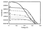
- FIG. 4 shows the voltage-current characteristics of the dye-sensitized solar cell and the voltage-current characteristics of the conventional dye-sensitized solar cell when silicon dioxide is variously changed.
- the horizontal axis represents voltage
- the vertical axis represents current.
- “1.0E-03” means 1.0 mA.
- the characteristic is the result of measuring the voltage and current between both FTO electrodes when the solar simulator is used and the incident light energy to the solar cell is 1-Sun (ie, 1 kW / m 2 ).
- FIG. 4 shows voltage-current characteristic curves of six samples A to E and G and a conventional dye-sensitized solar cell F which is a comparative sample.
- A is a voltage-current characteristic curve when finely pulverized artificial quartz particles having a particle size of 50 to 200 nm were used.
- the short-circuit current was 3067 ⁇ A and the open-circuit voltage was 660 mV.
- B is a voltage-current characteristic curve when artificial quartz particles having a particle diameter of 0.2 mm were used, and the short-circuit current was 2340 ⁇ A and the open-circuit voltage was 680 mV.
- D is a voltage-current characteristic curve when using fused silica, and the short-circuit current was 1293 ⁇ A and the open-circuit voltage was 680 mV.
- C is a voltage-current characteristic curve when using alkali-free glass, and the short-circuit current was 1850 ⁇ A and the open-circuit voltage was 690 mV.
- E is a voltage-current characteristic curve when borosilicate glass was used, and the short-circuit current was 930 ⁇ A and the open-circuit voltage was 700 mV.
- F is a voltage-current characteristic curve of the prior art dye-sensitized solar cell of FIG. 1, with a short-circuit current of 733 ⁇ A and an open-circuit voltage of 680 mV.
- G is a voltage-current characteristic curve when using soda-lime glass, the short-circuit current was 626 ⁇ A, and the open-circuit voltage was 670 mV.
- Example 1 shown in FIG. 3 the particle size of the finely pulverized artificial quartz crystal used is as small as 500 nm or less, and when applied to the platinum electrode and dried and then touched with the electrolyte, it is indicated by 22 in FIG. Thus, it may be dispersed and suspended in the electrolyte. Even in such a state, the current-voltage relationship of the silicon dioxide solar cell is not significantly affected.
- FIG. 6 shows a silicon dioxide solar cell of Example 3 obtained by improving Example 2 shown in FIG.
- the finely pulverized artificial quartz particles dispersed and suspended in the electrolyte have a fine particle size of 500 nm or less and are essentially poor conductors, so they enter the pores of porous titanium dioxide. There is a possibility that the electromotive ability of titanium dioxide is hindered. In order to prevent such a situation, an electrolyte in which silicon dioxide 22 is suspended is separated from an electrolyte in which silicon dioxide 22 is not suspended by a diaphragm 23 through which only the electrolyte can permeate.
- the container for containing the solar cell material and the electrolyte is made of a light transmissive material on the light incident side and a light transmissive or light opaque material on the light non-incident side.
- Glass, plastics, amorphous silicon, and polyester film can be used as the light-transmitting material, and a metal plate such as stainless steel and nickel is used as the light-impermeable material.
- Transparent conductor Most of the glass and plastic used as the light-transmitting material do not have conductivity, and when a material having no conductivity is used, it is necessary to impart conductivity.
- carbon-based materials such as AZO (Al—ZN—O), carbon nanotubes, graphene, etc., or conductive PET films, etc.
- a transparent conductive material such as ITO, carbon nanotube, or graphene is used, and an electrode formed on a transparent body such as glass or plastic is used. The transparent electrode is provided inside the solar cell.
- the side facing the light incident side of the solar cell storage container is a transparent electrode such as FTO, ITO, carbon nanotube, or graphene formed on a transparent material such as glass or plastic when it is necessary to transmit light.
- a transparent electrode such as FTO, ITO, carbon nanotube, or graphene formed on a transparent material such as glass or plastic when it is necessary to transmit light.
- a metal plate on which a charge extracting conductor such as carbon nanotube or graphene is formed is used.
- the electric charge extracting conductor is provided inside the solar cell.
- Crystalline artificial quartz grains or amorphous glass grains treated with hydrohalic acid were prepared as follows. An artificial quartz crystal made of silicon dioxide (SiO 2 ) or amorphous quartz glass, non-alkali glass, borosilicate glass, soda lime, etc. is immersed in a hydrofluoric acid aqueous solution, and then the artificial quartz The grains or glass grains were washed with water, dried, and then finely pulverized. In addition to hydrofluoric acid, hydrochloric acid is used as hydrohalic acid, but hydrofluoric acid is preferred. Other hydrohalic acids can also be used.
- the silicon dioxide particles are not treated with the hydrohalic acid, the silicon dioxide particles are pulverized to an average particle size of several tens of nanometers.
- the treatment of silicon dioxide particles with hydrohalic acid can be carried out after pulverization, not before pulverization.
- the silicon dioxide layer can be used even if a powder such as artificial quartz is mixed with platinum powder with ethanol and baked.
- a silicon dioxide particle fired body having a particle size of about 0.5 mm can be used.
- electrolyte various electrolytes such as cations such as lithium ions and anions such as chlorine ions are used as the supporting electrolyte, and oxidation-reduction pairs present in the electrolyte include oxidation of iodine-iodine compounds, bromine-bromine compounds, etc. Use reducing pairs.
- a thickener is added to 0.5 mol of lithium iodide (LiI) and 0.05 mol of metal iodine (I 2 ) dissolved in methoxypropionitrile. Added with butyl pyridine.
- a colored electrolyte such as an iodine-related electrolyte can be used.
- An organic acid such as acetic acid or citric acid can also be used as a colorless electrolyte.
- Titanium dioxide solar cells can also generate electricity in the ultraviolet and visible light regions by using sensitizing dyes, but they are expensive and have a short life when silicon dioxide solar cells generate sufficient power in the visible light region. There is no need to use any sensitizing dye.
- Counter electrode In addition to zinc oxide (ZnO), titanium oxide (TiO 2 ), copper oxide (CuO), magnesium oxide (MgO), strontium titanate (SrTiO 3 ), carbon nitride, graphene, etc. are used as the semiconductor layer for the counter electrode. Is possible.
- the silicon dioxide fired body is disposed on the surface where light does not enter. Since there is no absolute reason for this arrangement, the silicon dioxide fired body can be arranged on the surface on which light is incident.
- a useful solar cell can be obtained by being able to generate electricity by light in all regions from ultraviolet to infrared. .
Landscapes
- Engineering & Computer Science (AREA)
- Power Engineering (AREA)
- Microelectronics & Electronic Packaging (AREA)
- Chemical & Material Sciences (AREA)
- Chemical Kinetics & Catalysis (AREA)
- Electrochemistry (AREA)
- Hybrid Cells (AREA)
- Photovoltaic Devices (AREA)
Abstract
Afin d'augmenter le rendement de conversion d'une cellule solaire à dioxyde de titane poreux sensibilisé par colorant, deux substrats conducteurs sont agencés de telle sorte que les surfaces conductrices de ceux-ci se font face, au moins l'un des substrats étant un substrat côté entrée de lumière transparent, un comprimé fritté de dioxyde de titane poreux sensibilisé par colorant est disposé sur le substrat côté entrée de lumière, un comprimé de particules de dioxyde de silicium est disposé sur le substrat tourné vers le substrat côté entrée de lumière, et un électrolyte est chargé entre le comprimé fritté de dioxyde de titane poreux sensibilisé par colorant et le comprimé de particules de dioxyde de silicium. Des cellules solaires de dioxyde de titane poreux sensibilisé par colorant ayant cette configuration présentent un courant de court-circuit et une tension de décharge augmentés de manière significative par comparaison à des cellules solaires classiques.
Priority Applications (1)
| Application Number | Priority Date | Filing Date | Title |
|---|---|---|---|
| JP2013504720A JP6165054B2 (ja) | 2011-03-11 | 2012-03-12 | 光起電素子 |
Applications Claiming Priority (8)
| Application Number | Priority Date | Filing Date | Title |
|---|---|---|---|
| JP2011054609 | 2011-03-11 | ||
| JP2011-054609 | 2011-03-11 | ||
| JP2011-073152 | 2011-03-29 | ||
| JP2011073152 | 2011-03-29 | ||
| JP2011091389 | 2011-04-15 | ||
| JP2011-091389 | 2011-04-15 | ||
| JP2012-044753 | 2012-02-29 | ||
| JP2012044753 | 2012-02-29 |
Publications (1)
| Publication Number | Publication Date |
|---|---|
| WO2012124656A1 true WO2012124656A1 (fr) | 2012-09-20 |
Family
ID=46830725
Family Applications (2)
| Application Number | Title | Priority Date | Filing Date |
|---|---|---|---|
| PCT/JP2012/056291 Ceased WO2012124655A1 (fr) | 2011-03-11 | 2012-03-12 | Cellule solaire à dioxyde de silicium |
| PCT/JP2012/056292 Ceased WO2012124656A1 (fr) | 2011-03-11 | 2012-03-12 | Cellule solaire à dioxyde de silicium |
Family Applications Before (1)
| Application Number | Title | Priority Date | Filing Date |
|---|---|---|---|
| PCT/JP2012/056291 Ceased WO2012124655A1 (fr) | 2011-03-11 | 2012-03-12 | Cellule solaire à dioxyde de silicium |
Country Status (11)
| Country | Link |
|---|---|
| US (4) | US9384902B2 (fr) |
| EP (1) | EP2685554B1 (fr) |
| JP (2) | JP5848324B2 (fr) |
| AU (3) | AU2012227434B2 (fr) |
| DK (1) | DK2685554T3 (fr) |
| ES (1) | ES2895978T3 (fr) |
| LT (1) | LT2685554T (fr) |
| PL (1) | PL2685554T3 (fr) |
| SG (1) | SG193401A1 (fr) |
| TW (1) | TWI542023B (fr) |
| WO (2) | WO2012124655A1 (fr) |
Cited By (7)
| Publication number | Priority date | Publication date | Assignee | Title |
|---|---|---|---|---|
| WO2013129562A1 (fr) * | 2012-02-28 | 2013-09-06 | 国際先端技術総合研究所株式会社 | Plaque de verre composite pour cellule solaire |
| JP2014044881A (ja) * | 2012-08-27 | 2014-03-13 | International Frontier Technology Laboratory Inc | 複合ソーラーセル |
| JP2014116210A (ja) * | 2012-12-10 | 2014-06-26 | International Frontier Technology Laboratory Inc | 2酸化ケイ素ソーラーセル |
| JP2014120243A (ja) * | 2012-12-13 | 2014-06-30 | International Frontier Technology Laboratory Inc | 色素増感タンデム2酸化ケイ素ソーラーセル |
| JP2014130766A (ja) * | 2012-12-28 | 2014-07-10 | International Frontier Technology Laboratory Inc | 色素増感タンデム2酸化ケイ素ソーラーセル |
| WO2017119357A1 (fr) * | 2016-01-06 | 2017-07-13 | 国際先端技術総合研究所株式会社 | Élément photovoltaïque |
| CN108364579A (zh) * | 2018-02-10 | 2018-08-03 | 深圳市益鑫智能科技有限公司 | 方便夜间使用的建筑安全警示牌 |
Families Citing this family (5)
| Publication number | Priority date | Publication date | Assignee | Title |
|---|---|---|---|---|
| TWI542023B (zh) * | 2011-03-11 | 2016-07-11 | Internat Frontier Tech Lab Inc | Silicon dioxide solar cells |
| US10121601B2 (en) | 2012-05-22 | 2018-11-06 | International Frontier Technology Laboratory, Inc. | Photoelectrode material and photocell material |
| JP6457167B2 (ja) * | 2013-01-30 | 2019-01-23 | inQs株式会社 | 電流発生方法、キャパシタ型電源およびキャパシタ型電源を備えたセンサ |
| WO2019092827A1 (fr) * | 2017-11-09 | 2019-05-16 | International Frontier Technology Laboratory, Inc. | Système de gestion d'énergie de dispositif à semi-conducteur |
| JPWO2024014537A1 (fr) | 2022-07-14 | 2024-01-18 |
Citations (3)
| Publication number | Priority date | Publication date | Assignee | Title |
|---|---|---|---|---|
| JP2001243995A (ja) * | 2000-02-29 | 2001-09-07 | Fuji Photo Film Co Ltd | 光電変換素子および光電池 |
| JP2002170602A (ja) * | 2000-11-30 | 2002-06-14 | Hitachi Maxell Ltd | 光電変換素子 |
| JP2011028918A (ja) * | 2009-07-22 | 2011-02-10 | Shimane Prefecture | 色素増感太陽電池 |
Family Cites Families (20)
| Publication number | Priority date | Publication date | Assignee | Title |
|---|---|---|---|---|
| JPH0643246B2 (ja) * | 1985-10-08 | 1994-06-08 | 川鉄鉱業株式会社 | シリカの高純度化方法 |
| JP4214221B2 (ja) | 2003-03-25 | 2009-01-28 | 特許技術開発株式会社 | 光反応による窒素酸化物の除去方法 |
| JP4247780B2 (ja) | 2003-03-25 | 2009-04-02 | 独立行政法人産業技術総合研究所 | 新規光触媒及びそれを用いた有害有機物質の無害化処理方法 |
| JP2007307430A (ja) * | 2004-03-18 | 2007-11-29 | Tetsuo Yazawa | 新規な光触媒、その製造方法及びそれを用いた浄化方法 |
| JP4897226B2 (ja) | 2005-03-02 | 2012-03-14 | シャープ株式会社 | 色素増感型太陽電池および色素増感型太陽電池モジュール |
| JP4863662B2 (ja) | 2005-07-06 | 2012-01-25 | シャープ株式会社 | 色素増感型太陽電池モジュールおよびその製造方法 |
| EP1936644A3 (fr) * | 2006-12-22 | 2011-01-05 | Sony Deutschland Gmbh | Cellule photovoltaïque |
| JP2008257893A (ja) | 2007-03-30 | 2008-10-23 | Dainippon Printing Co Ltd | 色素増感型太陽電池用基板の製造方法、色素増感型太陽電池の製造方法、および、これらによって製造された色素増感型太陽電池用基板および色素増感型太陽電池。 |
| JP2009076448A (ja) * | 2007-08-28 | 2009-04-09 | Toray Ind Inc | 色素増感型太陽電池 |
| US8443502B2 (en) * | 2007-09-14 | 2013-05-21 | Ivoclar Vivadent Ag | Blank arrangement |
| KR100807238B1 (ko) * | 2007-10-09 | 2008-02-28 | 전남대학교산학협력단 | 유리분말이 함유된 염료감응형 태양전지 및 그 제조방법 |
| JP2010080315A (ja) * | 2008-09-26 | 2010-04-08 | Sumitomo Chemical Co Ltd | 色素増感型太陽電池 |
| JP2010182457A (ja) * | 2009-02-03 | 2010-08-19 | Toray Ind Inc | 色素増感太陽電池用セパレーター |
| US8530738B2 (en) * | 2009-03-11 | 2013-09-10 | National University Corporation Kyushu Institute Of Technology | Dye-sensitized solar cell |
| JP5322830B2 (ja) * | 2009-08-05 | 2013-10-23 | 日東電工株式会社 | ガラス製部材の接着方法 |
| AU2010308884A1 (en) | 2009-10-21 | 2012-05-10 | International Frontier Technology Laboratory, Inc. | Photoelectrode material and photocell material |
| WO2011063103A1 (fr) * | 2009-11-18 | 2011-05-26 | The Trustees Of Princeton University | Échafaudages en graphène microporeux revêtus de semi-conducteurs |
| KR101325646B1 (ko) * | 2010-09-16 | 2013-11-20 | 한국전자통신연구원 | 태양전지 및 그 형성방법 |
| TWI542023B (zh) * | 2011-03-11 | 2016-07-11 | Internat Frontier Tech Lab Inc | Silicon dioxide solar cells |
| US20130025657A1 (en) * | 2011-07-27 | 2013-01-31 | Jifa Qi | Plasmon enhanced dye-sensitized solar cells |
-
2012
- 2012-03-09 TW TW101108246A patent/TWI542023B/zh active
- 2012-03-12 JP JP2013504719A patent/JP5848324B2/ja active Active
- 2012-03-12 AU AU2012227434A patent/AU2012227434B2/en active Active
- 2012-03-12 LT LTEPPCT/JP2012/056291T patent/LT2685554T/lt unknown
- 2012-03-12 WO PCT/JP2012/056291 patent/WO2012124655A1/fr not_active Ceased
- 2012-03-12 WO PCT/JP2012/056292 patent/WO2012124656A1/fr not_active Ceased
- 2012-03-12 US US14/004,283 patent/US9384902B2/en active Active
- 2012-03-12 ES ES12757417T patent/ES2895978T3/es active Active
- 2012-03-12 EP EP12757417.6A patent/EP2685554B1/fr active Active
- 2012-03-12 PL PL12757417T patent/PL2685554T3/pl unknown
- 2012-03-12 JP JP2013504720A patent/JP6165054B2/ja active Active
- 2012-03-12 DK DK12757417.6T patent/DK2685554T3/da active
- 2012-03-12 SG SG2013068259A patent/SG193401A1/en unknown
-
2016
- 2016-06-07 US US15/175,602 patent/US9805878B2/en active Active
-
2017
- 2017-02-20 AU AU2017201115A patent/AU2017201115B2/en active Active
- 2017-02-20 AU AU2017201120A patent/AU2017201120B2/en active Active
- 2017-09-27 US US15/716,852 patent/US20180019067A1/en not_active Abandoned
-
2018
- 2018-05-07 US US15/973,159 patent/US20180261397A1/en not_active Abandoned
Patent Citations (3)
| Publication number | Priority date | Publication date | Assignee | Title |
|---|---|---|---|---|
| JP2001243995A (ja) * | 2000-02-29 | 2001-09-07 | Fuji Photo Film Co Ltd | 光電変換素子および光電池 |
| JP2002170602A (ja) * | 2000-11-30 | 2002-06-14 | Hitachi Maxell Ltd | 光電変換素子 |
| JP2011028918A (ja) * | 2009-07-22 | 2011-02-10 | Shimane Prefecture | 色素増感太陽電池 |
Cited By (12)
| Publication number | Priority date | Publication date | Assignee | Title |
|---|---|---|---|---|
| WO2013129562A1 (fr) * | 2012-02-28 | 2013-09-06 | 国際先端技術総合研究所株式会社 | Plaque de verre composite pour cellule solaire |
| JP2014044881A (ja) * | 2012-08-27 | 2014-03-13 | International Frontier Technology Laboratory Inc | 複合ソーラーセル |
| JP2014116210A (ja) * | 2012-12-10 | 2014-06-26 | International Frontier Technology Laboratory Inc | 2酸化ケイ素ソーラーセル |
| JP2014120243A (ja) * | 2012-12-13 | 2014-06-30 | International Frontier Technology Laboratory Inc | 色素増感タンデム2酸化ケイ素ソーラーセル |
| JP2014130766A (ja) * | 2012-12-28 | 2014-07-10 | International Frontier Technology Laboratory Inc | 色素増感タンデム2酸化ケイ素ソーラーセル |
| WO2014104327A3 (fr) * | 2012-12-28 | 2014-08-28 | 国際先端技術総合研究所株式会社 | Cellule solaire à dioxyde de silicium en tandem sensibilisée par colorant |
| WO2017119357A1 (fr) * | 2016-01-06 | 2017-07-13 | 国際先端技術総合研究所株式会社 | Élément photovoltaïque |
| CN108475582A (zh) * | 2016-01-06 | 2018-08-31 | 国际先端技术综合研究所株式会社 | 光发电元件 |
| AU2016385211B2 (en) * | 2016-01-06 | 2019-10-03 | International Frontier Technology Laboratory, Inc. | Photovoltaic element |
| CN108475582B (zh) * | 2016-01-06 | 2021-02-23 | 国际先端技术综合研究所株式会社 | 光发电元件 |
| CN108364579A (zh) * | 2018-02-10 | 2018-08-03 | 深圳市益鑫智能科技有限公司 | 方便夜间使用的建筑安全警示牌 |
| CN108364579B (zh) * | 2018-02-10 | 2020-08-14 | 安徽龙运智能科技有限公司 | 方便夜间使用的建筑安全警示牌 |
Also Published As
| Publication number | Publication date |
|---|---|
| JPWO2012124655A1 (ja) | 2014-07-24 |
| SG193401A1 (en) | 2013-10-30 |
| AU2017201115B2 (en) | 2018-10-25 |
| JP5848324B2 (ja) | 2016-01-27 |
| LT2685554T (lt) | 2021-10-25 |
| ES2895978T3 (es) | 2022-02-23 |
| EP2685554A4 (fr) | 2014-10-01 |
| AU2017201120A1 (en) | 2017-03-09 |
| DK2685554T3 (da) | 2021-10-11 |
| US9384902B2 (en) | 2016-07-05 |
| TWI542023B (zh) | 2016-07-11 |
| US20180019067A1 (en) | 2018-01-18 |
| US20160293340A1 (en) | 2016-10-06 |
| JPWO2012124656A1 (ja) | 2014-07-24 |
| JP6165054B2 (ja) | 2017-07-19 |
| AU2012227434A1 (en) | 2013-10-24 |
| AU2012227434B2 (en) | 2016-12-01 |
| US20140060630A1 (en) | 2014-03-06 |
| PL2685554T3 (pl) | 2022-01-17 |
| EP2685554B1 (fr) | 2021-08-04 |
| TW201251040A (en) | 2012-12-16 |
| US20180261397A1 (en) | 2018-09-13 |
| US9805878B2 (en) | 2017-10-31 |
| WO2012124655A1 (fr) | 2012-09-20 |
| EP2685554A1 (fr) | 2014-01-15 |
| AU2017201115A1 (en) | 2017-03-09 |
| AU2017201120B2 (en) | 2018-10-18 |
Similar Documents
| Publication | Publication Date | Title |
|---|---|---|
| JP5848324B2 (ja) | 2酸化ケイ素ソーラーセル | |
| Sauvage et al. | Effect of sensitizer adsorption temperature on the performance of dye-sensitized solar cells | |
| KR100696529B1 (ko) | 금속원소를 포함하는 광전변환소자용 전극 및 이를 채용한염료감응 태양전지 | |
| Yang et al. | Enhanced energy conversion efficiency of the Sr2+-modified nanoporous TiO2 electrode sensitized with a ruthenium complex | |
| WO2010143548A1 (fr) | Convertisseur photoélectrique sensibilisé par colorant, son procédé de fabrication et dispositif électronique | |
| Kim et al. | Effect of layer-by-layer assembled SnO2 interfacial layers in photovoltaic properties of dye-sensitized solar cells | |
| EP2716855A1 (fr) | Plaque de verre pour fenêtre | |
| JP5609800B2 (ja) | 色素増感型太陽電池 | |
| JP4387652B2 (ja) | 炭素電極及びこれを備えた色素増感型太陽電池 | |
| Seo et al. | Improvement on the electron transfer of dye-sensitized solar cell using vanadium doped TiO2 | |
| US20130244092A1 (en) | Electrode material for battery, electrode material paste for battery, and solar cell using same, storage battery, and method for manufacturing solar cell | |
| Jasim et al. | Henna (Lawsonia inermis L.) Dye‐Sensitized Nanocrystalline Titania Solar Cell | |
| EP3758032B1 (fr) | Élément photovoltaïque | |
| JP6227735B2 (ja) | タンデム型ソーラーセル | |
| JPH09237641A (ja) | 多孔質電極及びそれを用いた太陽電池 | |
| JP2012234693A (ja) | ソーラーセル | |
| WO2013151175A1 (fr) | Cellule solaire au dioxyde de silicium et plaque de verre comportant une structure de cellule solaire au dioxyde de silicium | |
| Hieu et al. | Enhancement of dye-sensitized solar cell efficiency by spherical voids in nanocrystalline ZnO electrodes | |
| JP2008027777A (ja) | 酸化チタン粒子含有組成物、光電極の製造方法及び太陽電池の製造方法 | |
| Amornkitbamrung | A dye sensitized solar cell using natural counter electrode and natural dye derived from mangosteen peel waste | |
| SI22807A (sl) | Postopek priprave paste in izdelava plasti titanovega dioksida z veliko notranjo povrĺ ino in dobro medsebojno povezavo nanodelcev ter dobro adhezijo na substrat |
Legal Events
| Date | Code | Title | Description |
|---|---|---|---|
| 121 | Ep: the epo has been informed by wipo that ep was designated in this application |
Ref document number: 12757901 Country of ref document: EP Kind code of ref document: A1 |
|
| ENP | Entry into the national phase |
Ref document number: 2013504720 Country of ref document: JP Kind code of ref document: A |
|
| NENP | Non-entry into the national phase |
Ref country code: DE |
|
| 122 | Ep: pct application non-entry in european phase |
Ref document number: 12757901 Country of ref document: EP Kind code of ref document: A1 |