WO2012124812A1 - Dispositif de freinage électrique à mécanisme de stationnement - Google Patents
Dispositif de freinage électrique à mécanisme de stationnement Download PDFInfo
- Publication number
- WO2012124812A1 WO2012124812A1 PCT/JP2012/056939 JP2012056939W WO2012124812A1 WO 2012124812 A1 WO2012124812 A1 WO 2012124812A1 JP 2012056939 W JP2012056939 W JP 2012056939W WO 2012124812 A1 WO2012124812 A1 WO 2012124812A1
- Authority
- WO
- WIPO (PCT)
- Prior art keywords
- rotation
- side engaging
- engaging member
- rotating
- restraining
- Prior art date
- Legal status (The legal status is an assumption and is not a legal conclusion. Google has not performed a legal analysis and makes no representation as to the accuracy of the status listed.)
- Ceased
Links
Images


Classifications
-
- F—MECHANICAL ENGINEERING; LIGHTING; HEATING; WEAPONS; BLASTING
- F16—ENGINEERING ELEMENTS AND UNITS; GENERAL MEASURES FOR PRODUCING AND MAINTAINING EFFECTIVE FUNCTIONING OF MACHINES OR INSTALLATIONS; THERMAL INSULATION IN GENERAL
- F16D—COUPLINGS FOR TRANSMITTING ROTATION; CLUTCHES; BRAKES
- F16D55/00—Brakes with substantially-radial braking surfaces pressed together in axial direction, e.g. disc brakes
- F16D55/02—Brakes with substantially-radial braking surfaces pressed together in axial direction, e.g. disc brakes with axially-movable discs or pads pressed against axially-located rotating members
- F16D55/22—Brakes with substantially-radial braking surfaces pressed together in axial direction, e.g. disc brakes with axially-movable discs or pads pressed against axially-located rotating members by clamping an axially-located rotating disc between movable braking members, e.g. movable brake discs or brake pads
- F16D55/224—Brakes with substantially-radial braking surfaces pressed together in axial direction, e.g. disc brakes with axially-movable discs or pads pressed against axially-located rotating members by clamping an axially-located rotating disc between movable braking members, e.g. movable brake discs or brake pads with a common actuating member for the braking members
- F16D55/225—Brakes with substantially-radial braking surfaces pressed together in axial direction, e.g. disc brakes with axially-movable discs or pads pressed against axially-located rotating members by clamping an axially-located rotating disc between movable braking members, e.g. movable brake discs or brake pads with a common actuating member for the braking members the braking members being brake pads
- F16D55/226—Brakes with substantially-radial braking surfaces pressed together in axial direction, e.g. disc brakes with axially-movable discs or pads pressed against axially-located rotating members by clamping an axially-located rotating disc between movable braking members, e.g. movable brake discs or brake pads with a common actuating member for the braking members the braking members being brake pads in which the common actuating member is moved axially, e.g. floating caliper disc brakes
-
- B—PERFORMING OPERATIONS; TRANSPORTING
- B60—VEHICLES IN GENERAL
- B60T—VEHICLE BRAKE CONTROL SYSTEMS OR PARTS THEREOF; BRAKE CONTROL SYSTEMS OR PARTS THEREOF, IN GENERAL; ARRANGEMENT OF BRAKING ELEMENTS ON VEHICLES IN GENERAL; PORTABLE DEVICES FOR PREVENTING UNWANTED MOVEMENT OF VEHICLES; VEHICLE MODIFICATIONS TO FACILITATE COOLING OF BRAKES
- B60T1/00—Arrangements of braking elements, i.e. of those parts where braking effect occurs specially for vehicles
- B60T1/005—Arrangements of braking elements, i.e. of those parts where braking effect occurs specially for vehicles by locking of wheel or transmission rotation
-
- B—PERFORMING OPERATIONS; TRANSPORTING
- B60—VEHICLES IN GENERAL
- B60T—VEHICLE BRAKE CONTROL SYSTEMS OR PARTS THEREOF; BRAKE CONTROL SYSTEMS OR PARTS THEREOF, IN GENERAL; ARRANGEMENT OF BRAKING ELEMENTS ON VEHICLES IN GENERAL; PORTABLE DEVICES FOR PREVENTING UNWANTED MOVEMENT OF VEHICLES; VEHICLE MODIFICATIONS TO FACILITATE COOLING OF BRAKES
- B60T13/00—Transmitting braking action from initiating means to ultimate brake actuator with power assistance or drive; Brake systems incorporating such transmitting means, e.g. air-pressure brake systems
- B60T13/74—Transmitting braking action from initiating means to ultimate brake actuator with power assistance or drive; Brake systems incorporating such transmitting means, e.g. air-pressure brake systems with electrical assistance or drive
- B60T13/741—Transmitting braking action from initiating means to ultimate brake actuator with power assistance or drive; Brake systems incorporating such transmitting means, e.g. air-pressure brake systems with electrical assistance or drive acting on an ultimate actuator
-
- F—MECHANICAL ENGINEERING; LIGHTING; HEATING; WEAPONS; BLASTING
- F16—ENGINEERING ELEMENTS AND UNITS; GENERAL MEASURES FOR PRODUCING AND MAINTAINING EFFECTIVE FUNCTIONING OF MACHINES OR INSTALLATIONS; THERMAL INSULATION IN GENERAL
- F16D—COUPLINGS FOR TRANSMITTING ROTATION; CLUTCHES; BRAKES
- F16D63/00—Brakes not otherwise provided for; Brakes combining more than one of the types of groups F16D49/00 - F16D61/00
- F16D63/006—Positive locking brakes
-
- F—MECHANICAL ENGINEERING; LIGHTING; HEATING; WEAPONS; BLASTING
- F16—ENGINEERING ELEMENTS AND UNITS; GENERAL MEASURES FOR PRODUCING AND MAINTAINING EFFECTIVE FUNCTIONING OF MACHINES OR INSTALLATIONS; THERMAL INSULATION IN GENERAL
- F16D—COUPLINGS FOR TRANSMITTING ROTATION; CLUTCHES; BRAKES
- F16D65/00—Parts or details
- F16D65/14—Actuating mechanisms for brakes; Means for initiating operation at a predetermined position
- F16D65/16—Actuating mechanisms for brakes; Means for initiating operation at a predetermined position arranged in or on the brake
- F16D65/18—Actuating mechanisms for brakes; Means for initiating operation at a predetermined position arranged in or on the brake adapted for drawing members together, e.g. for disc brakes
-
- F—MECHANICAL ENGINEERING; LIGHTING; HEATING; WEAPONS; BLASTING
- F16—ENGINEERING ELEMENTS AND UNITS; GENERAL MEASURES FOR PRODUCING AND MAINTAINING EFFECTIVE FUNCTIONING OF MACHINES OR INSTALLATIONS; THERMAL INSULATION IN GENERAL
- F16D—COUPLINGS FOR TRANSMITTING ROTATION; CLUTCHES; BRAKES
- F16D2121/00—Type of actuator operation force
- F16D2121/18—Electric or magnetic
- F16D2121/24—Electric or magnetic using motors
-
- F—MECHANICAL ENGINEERING; LIGHTING; HEATING; WEAPONS; BLASTING
- F16—ENGINEERING ELEMENTS AND UNITS; GENERAL MEASURES FOR PRODUCING AND MAINTAINING EFFECTIVE FUNCTIONING OF MACHINES OR INSTALLATIONS; THERMAL INSULATION IN GENERAL
- F16D—COUPLINGS FOR TRANSMITTING ROTATION; CLUTCHES; BRAKES
- F16D2125/00—Components of actuators
- F16D2125/18—Mechanical mechanisms
- F16D2125/20—Mechanical mechanisms converting rotation to linear movement or vice versa
- F16D2125/34—Mechanical mechanisms converting rotation to linear movement or vice versa acting in the direction of the axis of rotation
- F16D2125/36—Helical cams, Ball-rotating ramps
-
- F—MECHANICAL ENGINEERING; LIGHTING; HEATING; WEAPONS; BLASTING
- F16—ENGINEERING ELEMENTS AND UNITS; GENERAL MEASURES FOR PRODUCING AND MAINTAINING EFFECTIVE FUNCTIONING OF MACHINES OR INSTALLATIONS; THERMAL INSULATION IN GENERAL
- F16D—COUPLINGS FOR TRANSMITTING ROTATION; CLUTCHES; BRAKES
- F16D2125/00—Components of actuators
- F16D2125/18—Mechanical mechanisms
- F16D2125/20—Mechanical mechanisms converting rotation to linear movement or vice versa
- F16D2125/34—Mechanical mechanisms converting rotation to linear movement or vice versa acting in the direction of the axis of rotation
- F16D2125/40—Screw-and-nut
-
- F—MECHANICAL ENGINEERING; LIGHTING; HEATING; WEAPONS; BLASTING
- F16—ENGINEERING ELEMENTS AND UNITS; GENERAL MEASURES FOR PRODUCING AND MAINTAINING EFFECTIVE FUNCTIONING OF MACHINES OR INSTALLATIONS; THERMAL INSULATION IN GENERAL
- F16D—COUPLINGS FOR TRANSMITTING ROTATION; CLUTCHES; BRAKES
- F16D2125/00—Components of actuators
- F16D2125/18—Mechanical mechanisms
- F16D2125/44—Mechanical mechanisms transmitting rotation
- F16D2125/46—Rotating members in mutual engagement
- F16D2125/48—Rotating members in mutual engagement with parallel stationary axes, e.g. spur gears
-
- F—MECHANICAL ENGINEERING; LIGHTING; HEATING; WEAPONS; BLASTING
- F16—ENGINEERING ELEMENTS AND UNITS; GENERAL MEASURES FOR PRODUCING AND MAINTAINING EFFECTIVE FUNCTIONING OF MACHINES OR INSTALLATIONS; THERMAL INSULATION IN GENERAL
- F16D—COUPLINGS FOR TRANSMITTING ROTATION; CLUTCHES; BRAKES
- F16D2127/00—Auxiliary mechanisms
- F16D2127/06—Locking mechanisms, e.g. acting on actuators, on release mechanisms or on force transmission mechanisms
Definitions
- the present invention relates to an improvement of an electric brake device with a parking mechanism that generates a braking force using an electric motor as a drive source and that can maintain the braking force even after energization of the electric motor is stopped.
- the electric disc brake device that uses an electric motor as the drive source eliminates the need for hydraulic piping compared to the conventional hydraulic disc brake device, which makes it easier to manufacture and lower costs. There are many advantages, such as the fact that there is no used brake fluid, the environmental load is small, and there is no movement of the brake fluid. In addition, research is also being conducted on a disc brake device that uses only a parking mechanism as an electric motor for the reason that it is easy to control when starting a hill while ensuring the reliability of the hydraulic disc brake device.
- the output of the electric motor is input to a force-increasing mechanism, and this force-increasing mechanism converts the rotational motion of this electric motor into a linear motion while increasing the force, and the pair of pads are arranged on both sides of the brake rotor.
- a force-increasing mechanism converts the rotational motion of this electric motor into a linear motion while increasing the force
- the pair of pads are arranged on both sides of the brake rotor.
- Patent Documents 1 to 3 an electric brake device with a parking mechanism that can maintain a braking force even after energization of the electric motor is stopped has been known. .
- any of the electric brake devices with a parking mechanism described in each of the above-mentioned patent documents converts the rotary motion of the output shaft of the electric motor into a linear motion and presses both pads against the brake rotor.
- the parking lock device is required to have a function of continuously pressing both pads against the brake rotor even after the electric power supply to the electric motor is stopped. Further, for safety, it is necessary to have a structure in which the parking lock device is not inadvertently activated at the time of failure.
- any of the inventions described in the respective patent documents are provided, but both have a complicated structure and cost. It is inevitable that the volume increases.
- the structure in which the parking lock device does not operate at the time of failure the structure of the invention described in Patent Documents 1 and 2 is provided, but the structure of the invention described in Patent Document 3 is not provided.
- the present invention includes a parking lock device that uses an electric motor as a drive source and can maintain a braking force even after the electric power supply to the electric motor is stopped. It is an object of the present invention to provide an electric brake device with a parking mechanism which is relatively simple, can be made small and at low cost, and the parking locking device does not operate in advance.
- the above object of the present invention is achieved by an electric brake device with a parking mechanism having the following configuration.
- the electric brake device with a parking mechanism includes a braking rotator, a support member, a braking friction member, an electric pressing device, and a parking lock device.
- the brake rotator rotates with the wheel, and corresponds to a brake rotor constituting a disc brake device or a drum constituting a drum brake device.
- the support member is supported by a non-rotating portion adjacent to the braking rotator, and supports (in the case of a floating caliper type disc brake device) or caliper (opposing the disc brake device). In the case of a piston-type disc brake device), or a back plate constituting a drum brake device.
- the braking friction member is configured such that a part of the support member is opposed to a part of the braking rotating body (both axial side surfaces of the brake rotor and an inner peripheral surface of the drum). It is supported so that it can move with respect to the body.
- the electric pressing device uses an electric motor as a drive source and moves the braking friction member in a direction approaching the braking rotating body via a speed reduction mechanism.
- the parking lock device keeps the braking friction member pressed against the braking rotator even after the energization of the electric motor is stopped.
- the parking lock device in the electric brake device with a parking mechanism includes a rotation side engagement member, a suppression side engagement member, an elastic member, and an electric actuator.
- the rotation-side engagement member is fixed to a part of a rotation shaft that rotates when the electric motor is energized, and has a rotation-side engagement surface concentric with the rotation shaft.
- the rotating side engaging member has a predetermined direction based on a reaction of the braking force in a state where the braking friction member is pressed against the braking rotating body by the electric pressing device to generate a braking force. Torque to rotate is applied.
- the restraining side engaging member can be displaced in the direction of moving to and away from the rotating side engaging surface directly or via another member with respect to the support member, and can rotate around the rotation axis.
- the tip is configured to be detachable from the rotation-side engagement surface.
- the rotation side engagement protrusion is formed in the circumferential direction several places of the said rotation side engagement surface, The circumferential direction one side surface of each of these rotation side engagement protrusions is the displacement direction of the said suppression side engagement member. It is set as the inclined side inclined with respect to.
- the engagement margin with the distal end portion of the deterring-side engagement member increases. It is inclined in the direction.
- the elastic member imparts elasticity in a direction away from the rotation side engagement member to the inhibition side engagement member.
- the electric actuator is for applying a force in a direction approaching the rotation side engagement member against the elasticity of the elastic member to the inhibition side engagement member based on energization,
- a direct acting solenoid can be used.
- rotation-side engagement surface is an outer peripheral surface of the rotation-side engagement member, and a plurality of rotation-side engagement protrusions are formed on the outer peripheral surface. Is done. Further, one circumferential side surface of each of the rotation side engaging protrusions is inclined with respect to the displacement direction of the restraining side engaging member. In addition, although it is preferable to form these rotation side engaging protrusions at equal intervals in the circumferential direction, it is not always necessary to have equal intervals.
- the restraining side engaging member is disposed around the rotating side engaging member, and can be displaced in the radial direction of the rotating side engaging member.
- a surface that engages with one circumferential side surface of each of the rotation side engaging projections on one circumferential side surface of the distal end portion of the restraining side engaging member is a circumference of each of these rotation side engaging projections. It is inclined in the same direction as one side of the direction.
- rotation-side engagement surface is an outer peripheral surface of the rotation-side engagement member, and a plurality of rotation-side engagement protrusions are formed on the outer peripheral surface. Then, one circumferential side surface of each of the rotation side engagement protrusions is inclined with respect to the axial direction of the rotation side engagement member. Further, the restraining side engaging member is disposed in a portion near the outer diameter of the rotating side engaging member, and can be displaced in the axial direction of the rotating side engaging member.
- the operation of the electric brake device with a parking mechanism configured as in the above (1) is as follows. At the time of braking, by energizing the electric motor constituting the electric pressing device, a braking friction member such as a brake pad and a brake shoe is pressed against a braking rotating body such as a brake rotor and a brake drum, thereby A braking force is applied to the wheels that rotate with the rotating body.
- a service brake device that decelerates or further stops a traveling vehicle, a force that appropriately regulates an energization amount to the electric motor and presses the braking friction member against the braking rotator Adjust.
- the electric actuator is not energized, and the distal end portion of the restraining side engaging member is retracted from the rotating side engaging member based on the elasticity of the elastic member. Accordingly, the restraining side engaging member does not affect the operation of the electric pressing device.
- the actuator is operated in a state where the braking friction member is pressed against the braking rotating body by the electric pressing device to generate a braking force.
- Energize to Based on this energization, the restraining side engaging member is displaced against the elastic force of the elastic member, and the distal end portion of the restraining side engaging member and the rotating side engaging projection of the rotating side engaging member are And overlapping with respect to the rotation direction of the rotation-side engagement member. In other words, the distal end portion of the restraining side engaging member and the inclined side of the rotating side engaging projection of the rotating side engaging member are brought into an engageable state with the rotation of the rotating side engaging member.
- the rotation-side engagement member tends to rotate in a predetermined direction based on the reaction of the braking force, and the tip end portion of the inhibition-side engagement member and the rotation-side engagement protrusion of the rotation-side engagement member are inclined.
- the sides engage.
- power supply to the actuator is stopped.
- the restraining side engaging member tends to be displaced in the direction of releasing the engagement with the rotating side engaging projection based on the elasticity of the elastic member.
- the inclined side is inclined in a direction in which the engagement with the distal end portion of the restraining side engaging member becomes larger as it goes forward in this direction.
- the braking friction member can be kept pressed against the braking rotator without energizing any part. In other words, the braking force can be secured without consuming the power source such as the battery.
- the restraining side engaging member is displaced in the direction of retreating from the rotating side engaging member by the elastic force of the elastic member, and the restraining side engagement is The tip of the member is not engaged with the rotation side engagement protrusion of the rotation side engagement member. For this reason, the operation of the electric pressing device is not impaired by the failure of the actuator. In other words, the operation of the service brake device is not impaired by the failure of the actuator, which is a parking brake component.
- the parking locking device is not inadvertently activated in the event of a failure, and can be configured relatively easily, and is small and low cost.
- An electric brake device with a parking mechanism can be realized.
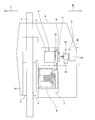
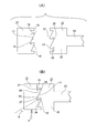
- FIG. 1 is a schematic diagram showing a first example of an embodiment of the present invention.
- FIG. 2 is a schematic view corresponding to part A of FIG. 1 showing a part of the parking brake locking device of the first example of the embodiment of the present invention.
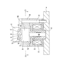
- FIG. 3 is a cross-sectional view corresponding to a portion B in FIG. 2, showing a more specific structure of the first example of the embodiment of the present invention.
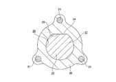
- 4 is a cross-sectional view taken along the line CC of FIG. 5 (A) and 5 (B) are side views showing the rotating side engaging member and the restraining side engaging member, FIG. 5 (A) shows the non-engaged state, and FIG. 5 (B) shows the engaging state. Indicates the status.
- FIG. 5 (A) shows the non-engaged state
- FIG. 5 (B) shows the engaging state. Indicates the status.
- FIG. 5 (A) shows the non-engaged state
- FIG. 5 (B) shows the engaging state. Indicates the status.
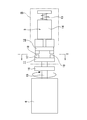
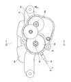
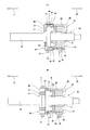
- FIG. 6 is a more specific cross-sectional view showing a second example of the embodiment of the present invention.
- the lower left portion represents the DD cross section of FIG. 7, and the upper right portion represents the EE cross section of FIG. ing.
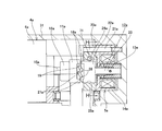
- 7 is a cross-sectional view taken along the line FF in FIG.
- FIG. 8 is a view from above of FIG.
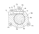
- FIG. 9 is an enlarged view of a portion G in FIG. 20 is a cross-sectional view taken along the line HH of FIG. 11 (A) and 11 (B) are longitudinal sectional views showing a state in which a unit combining the force increasing mechanism and the axial force sensor is taken out, and
- FIG. 11 (A) shows a state assembled to the caliper.
- (B) shows a state before assembly.
- FIG. 11 (A) shows a state assembled to the caliper.
- FIG. 11 (B) shows a state before assembly.
- FIG. 11 (A) shows a state assembled to the caliper.
- FIG. 12 is a view corresponding to the II sectional view of FIG. 2 showing a third example of the embodiment of the present invention.
- FIG. 13 is a view similar to FIG. 12 showing a fourth example of the embodiment of the present invention.
- FIG. 14 is a view taken in the direction of arrow J in FIG.
- FIGS. 1 to 5B show a first example of an embodiment of the present invention corresponding to the above-described configurations (1) to (3).
- the structure of the first example of the present embodiment is shown when the present invention is applied to a floating caliper type disc brake device.
- the electric disk brake device with a parking mechanism (electric brake device with a parking mechanism) of the first example of the present embodiment includes a brake rotor 1 that is a braking rotator and a support that is a support member (not shown). ), An inner pad 2 and an outer pad 3, each of which is a friction member for braking, an electric pressing device 4, and a parking lock device 5.
- the brake rotor 1 is fixed concentrically with a wheel (not shown) and rotates together with the wheel.
- the support is provided adjacent to the brake rotor 1 so as to straddle a part of the brake rotor 1 in the circumferential direction, and is supported and fixed to a non-rotating portion such as a knuckle constituting the suspension device.
- the structure and function of the support that constitutes such a floating caliper type disc brake device is well known in the art as a hydraulic disc brake device that has been generally practiced. Since it is well known and described in many documents such as Patent Document 4, illustration and description are omitted.
- the inner pad 2 and the outer pad 3 are opposed to the both sides in the axial direction of the brake rotor 1 at a part of the support that sandwiches a part in the circumferential direction of the brake rotor 1 from both sides in the axial direction.
- the brake rotor 1 is supported so as to be capable of moving in a perspective direction. That is, the inner pad 2 and the outer pad 3 are supported so as to be displaced along the axial direction of the brake rotor 1.
- the electric pressing device 4 linearly rotates the movement, such as an electric motor 6 as a driving source, a speed reduction mechanism 7 having reversibility with respect to a power transmission direction, such as a gear type reduction gear, and a ball screw mechanism. It is provided with a thrust generating mechanism 8 that converts it into motion, and is installed in a caliper 9.
- the caliper 9 is supported by the support so as to be capable of displacement along the axial direction of the brake rotor 1.
- the thrust generating mechanism 8 presses the inner pad 2 against the inner side surface of the brake rotor 1.
- the thrust generating mechanism 8 is also reversible with respect to the direction of force transmission.
- the caliper 9 is displaced toward the inner side with respect to the support, and a caliper claw 10 provided at an outer side end portion of the caliper 9 places the outer pad 3 on the outer side surface of the brake rotor 1. Press. In this state, the brake rotor 1 is strongly clamped by the outer pad 3 and the inner pad 2 from both sides in the axial direction, and braking is performed.
- the parking lock device 5 is provided to keep the inner and outer pads 2 and 3 pressed against both side surfaces in the axial direction of the brake rotor 1 even after the energization of the electric motor 6 is stopped. ing.
- the parking lock device 5 having such a role includes a rotation-side engagement member 11, a suppression-side engagement member 12, a coil-type compression spring 13 that is an elastic member, and a solenoid 14 that is an electric actuator. With.
- the rotation-side engaging member 11 is fixed to the distal end portion of the output shaft 15 of the electric motor 6 together with the reduction gear 16 constituting the reduction mechanism 7.
- a portion closer to the outer diameter of the distal end surface (surface opposite to the main body portion of the electric motor 6) of the rotation side engagement member 11 is a rotation side engagement surface 17 concentric with the output shaft 15.
- the shape of the rotation-side engaging surface 17 in the circumferential direction is asymmetric with respect to the circumferential direction (the top of the wave is biased toward the circumferential direction). Yes.
- a plurality of rotation-side engagement protrusions 18 and 18 are formed at equal intervals in the circumferential direction on a portion near the outer diameter of the distal end surface of the rotation-side engagement member 11, Has been.
- Each of the rotation-side engaging protrusions 18 and 18 has a triangular shape with an acute apex angle, and is inclined in the direction toward the same side with respect to the circumferential direction from the base portion toward the top portion. For this reason, both the circumferential side surfaces of the rotation-side engaging projections 18, 18 are both inclined with respect to the axial direction of the output shaft 15.
- one circumferential side surface that is a surface facing the proximal end side of the rotation side engagement member 11 with respect to the axial direction is an inclined side 19. , 19.
- the speed reduction mechanism 7 including the speed reduction small gear 16 and the thrust generation mechanism 8 have reversibility with respect to the transmission direction of power or force. Because of this reversibility, the rotation-side engagement member 11 reacts to the reaction of the braking force in a state where the inner pad 2 and the outer pad 3 are pressed against both axial side surfaces of the brake rotor 1 to generate a braking force. Based on this, a torque to rotate in a predetermined direction is applied.
- the direction in which this torque acts is the direction in which the tops of the respective rotation-side engaging projections 18 and 18 are located on the front side in the rotation direction, in other words, the direction in which the respective inclined sides 19 and 19 are front surfaces with respect to the rotation direction. .
- the restraining side engaging member 12 and the solenoid 14 are fixed inside the caliper 9. Therefore, on the inner surface of the caliper 9, the annularly configured solenoid 14 and the holder 20 for supporting the restraining side engaging member 12 are overlapped from the inner surface side of the caliper 9. These are fixed by a plurality of (three in the illustrated example) mounting bolts 21, 21.
- the restraining side engaging member 12 has a large-diameter head portion 22 at a distal end portion and a small-diameter flange portion 23 at an intermediate portion or a proximal end portion.
- the material of the restraining side engaging member 12 is not particularly limited as long as sufficient strength and rigidity can be ensured, such as metal and synthetic resin.
- a magnetic material is fixed to at least a part so that the restraining side engaging member 12 can be displaced in the axial direction by the solenoid 14.
- the outer peripheral surface of the head portion 22 of such a restraining side engaging member 12 is a non-cylindrical surface having a flat portion 24 in a part in the circumferential direction.
- Such a head 22 is fitted in the holding hole 25 of the holder 20.
- the inner peripheral surface of the holding hole 25 is also a non-cylindrical surface having a flat portion 26 in a part of the circumferential direction.
- the shape of the portion near the outer diameter of the distal end surface of the head portion 22 is a shape that can be engaged with and disengaged from the rotating side engaging surface 17. That is, the same number of restraining side engaging projections 27, 27 as the rotational side engaging projections 18, 18 on the distal end surface of the rotational side engaging member 11 are provided on the outer diameter portion of the distal end surface of the head portion 22. It is formed at equal intervals in the direction.
- Each of the restraining side engaging protrusions 27 and 27 is triangular with an acute angle, similar to the rotating side engaging protrusions 18 and 18, and is on the same side in the circumferential direction from the base to the top. Inclined in the direction of heading.
- both circumferential side surfaces of the restraining side engaging projections 27 are inclined with respect to the axial direction of the restraining side engaging member 12 (the axial direction of the output shaft 15).
- the direction in which both circumferential side surfaces of the restraining side engaging projections 27, 27 are inclined is opposite to the rotating side engaging projections 18, 18.
- the surfaces in contact with the respective inclined sides 19, 19 on the side are second inclined sides 28, 28 that are inclined in the same direction as these inclined sides 19, 19 by substantially the same angle ⁇ .
- the inclined sides 19 and 19 on the rotating engagement member 11 side and the second inclined sides 28 and 28 on the restraining engagement member 12 side are respectively connected to the rotating engagement protrusions 18 and 18.
- the side engaging protrusions 18 and 27 are inclined in a direction in which the dimension (the dimension in which the side engaging protrusions 18 and 27 overlap with each other in the axial direction) increases.
- the restraining side engaging member 12 as described above is given elasticity in a direction away from the rotating side engaging member 11 by the compression spring 13, and the solenoid 14 resists this elasticity (from this elasticity). (With a great force), the rotating side stationary member 11 is brought close to the rotating side stationary member 11. That is, the restraining side engaging member 12 can be reciprocated in the axial direction by turning the solenoid 14 on and off.
- the elastic force of the compression spring 13 is such that when the inclined sides 19 and 28 are in contact with each other by the torque applied to the rotation side engagement member 11 based on the reaction force of the braking force,
- the joint member 12 is kept at a small value so as not to be displaced in a direction away from the rotation side engaging member 11.
- the magnitude of the tangential force applied to the rotating engagement member 11 based on the reaction force is F
- the inclination angle of the inclined sides 19 and 28 with respect to the direction of the force is ⁇ .
- ⁇ is the coefficient of friction of the contact portion of each of the inclined sides 19 and 29
- W is the magnitude of the elasticity of the compression spring 13.
- the magnitude W of the elasticity, the inclination angle ⁇ , and the like are regulated.
- the thrust generating mechanism 8 is extended by energizing the electric motor 6, and the inner pad 2. Is pressed against the inner side surface of the brake rotor 1.
- the caliper 9 is displaced toward the inner side, and the outer pad 3 is pressed against the outer side surface of the brake rotor 1 by the caliper pawl 10.
- the brake rotor 1 is firmly clamped from both sides by the inner pads 2 and the outer pad 3, and a braking force is applied to the wheels rotating together with the brake rotor 1.
- the magnitude of the braking force is adjusted by regulating the amount of current supplied to the electric motor 6 and adjusting the torque input from the output shaft 15 to the thrust generating mechanism 8 via the speed reduction mechanism 7.
- the solenoid 14 is not energized, and the restraining side engaging member 12 is moved to its tip portion based on the elasticity of the compression spring 13 as shown in FIG. Is retracted from the rotation-side engagement member 11. Therefore, the restraining side engaging member 12 does not affect the operation of the electric pressing device 4 including the electric motor 6.
- the electric pressing device 4 presses the inner pad 2 and the outer pad 3 against both side surfaces of the brake rotor 1 to generate a braking force. Then, the solenoid 14 is energized (turned on). Based on this energization, the restraining side engaging member 12 is displaced in a direction approaching the rotating side engaging member 11 against the elasticity of the compression spring 13. The restraining side engaging protrusions 27 and 27 projecting in the axial direction from the distal end surface of the restraining side engaging member 12 and the rotating sides projecting in the axial direction from the distal end surface of the rotating side engaging member 11.
- the engagement protrusions 18 and 18 overlap with each other with respect to the rotation direction of the rotation-side engagement member 11.
- the tip end portions of the respective restraining side engaging projections 27, 27 enter between the respective rotating side engaging projections 18, 18 adjacent in the circumferential direction, and the respective restraining side engaging projections 27, 27, and the inclined sides 19, 19 of the rotation-side engagement protrusions 18, 18 of the rotation-side engagement member 11 are associated with the rotation of the rotation-side engagement member 11. It becomes possible to match.
- the rotation-side engagement member 11 does not rotate further in the direction of reducing the braking force.
- the amount (angle) by which the rotating side engaging member 11 rotates until the inclined sides 28 and 19 engage with each other is small, and the rotating side engaging member 11, the inner pad 2 and the outer pad 3 are small.
- the speed reduction mechanism 7 and the thrust generation mechanism 8 having a large power increase ratio (speed reduction ratio) exist between the power generation mechanism 8 and the power generation mechanism 8. Therefore, the decrease in the braking force accompanying the rotation of the rotation-side engaging member 11 until the inclined sides 28 and 19 are engaged with each other is negligibly small. Therefore, as shown in FIG. 5B, the energization of the solenoid 14 is stopped (turned off) while the inclined sides 28 and 19 are engaged with each other.
- the inhibition-side engagement member 12 tends to retract from the rotation-side engagement member 11 based on the elasticity of the compression spring 13.
- the rotation-side engagement protrusions 18 and 18 on the tip surface of the rotation-side engagement member 11 and the tip surface of the restraining-side engagement member 12 The engagement with the restraining side engaging protrusions 27, 27 tends to be disengaged.
- the inclined sides 28 and 19 are inclined in a direction in which the engagement margin between the engaging protrusions 18 and 27 increases as the rotation-side engaging protrusions 18 and 27 are displaced in the disengagement direction. .
- the elasticity of the compression spring 13 and the inclination angle ⁇ of the inclined sides 28 and 19 are appropriately restricted as described above. Therefore, even after the solenoid 14 is turned off, the engagement protrusions 18 and 27 can be kept engaged with each other.
- the restraining side engaging projections 27 and 27 and the rotating side engaging projections 18 and 18 are caused to react with each other by a reaction force based on a braking force.
- a force in the rotation direction of the rotation side engagement members and the suppression side engagement members 11 and 12 is applied.
- this force is also reduced by the large increase ratio (it is a small value obtained by dividing the reaction force by this increase ratio even if the friction is ignored). Even if the strength is not particularly increased, sufficient durability can be ensured.
- the rotating side engaging member 11 is slightly rotated in the direction of increasing the braking force by energizing the electric motor 6. At this time, the solenoid 14 is kept OFF. Then, the rotation-side engagement member 11 is rotated until the engagement margin between the engagement protrusions 18 and 27 is lost (the ends of the engagement protrusions 18 and 27 are not overlapped in the axial direction).
- the restraining side engaging member 12 is retracted from the rotating side engaging member 11 based on the elasticity of the compression spring 13, and the engaging projections 18 and 28 are disengaged from each other.
- the engaging member 11 can rotate, and the force that presses the inner pad 2 and the outer pad 3 against both side surfaces in the axial direction of the brake rotor 1 is lost.
- the restraining side engaging member 12 is displaced in a direction of retreating from the rotating side engaging member 11 by the elasticity of the compression spring 13, and the The engagement protrusions 18 and 27 are not engaged with each other.
- the malfunction of the solenoid 14 does not impair the operation of the electric pressing device 4, and the malfunction of the solenoid 14, which is a parking brake component, does not impair the operation of the service brake device.
- the parking locking device is not inadvertently activated in the event of a failure, and it is possible to realize a compact and low-cost electric disc brake device with a parking mechanism that can be configured relatively easily.
- FIG. 6 to FIG. 11B show a second example of the embodiment of the present invention more concretely corresponding to the above-described configurations (1) to (3).
- the second example of the present embodiment also shows the case where the present invention is applied to a floating caliper type disc brake device. Therefore, in the case of the second example of the present embodiment, the electric motor 6a, the speed reduction mechanism 7a, and the thrust generation mechanism 8a constituting the electric pressing device 4a are assembled to the caliper 9a. Is supported so as to be capable of displacement in the axial direction (left-right direction in FIG. 6) of the brake rotor 1a with respect to a support (not shown).
- the thrust generating mechanism 8 a is configured by a combination of a feed screw mechanism 29 and a ball ramp mechanism 30.
- the structure and operation of such a thrust generating mechanism 8a are basically the same as the conventional structure described in Patent Document 5.
- the thrust generating mechanism 8a has a structure in which a feed screw mechanism 29 and a ball ramp mechanism 30 as shown in the figure are combined, or a ball screw mechanism as in the first example of the above-described embodiment.
- various mechanical force-increasing mechanisms that convert the axial force while increasing the force in the rotational direction, such as a cam roller mechanism, can be employed.
- the electric motor 6a, the speed reduction mechanism 7a, and the parking lock device 5a are housed in a casing 31 fixed to the caliper 9a. Further, at the tip of the output shaft 15a of the electric motor 6a, the rotation side engaging member 11a and the reduction gear 16a are fitted and fixed concentrically with each other in order from the tip side of the output shaft 15a (spline engagement). Are combined). Of these, rotation-side engagement protrusions 18a and 18a are formed on the tip end surface (the right end surface in FIGS. 6 and 9) of the rotation-side engagement member 11a.
- each of the rotation-side engagement protrusions 18a and 18a the rotation-side engagement protrusions 18 and 18 (see, for example, FIG. 5A) of the rotation-side engagement member 11 of the first example of the embodiment described above. It is the same.
- the speed reduction mechanism 7a is shown in FIG. 7 between the speed reduction small gear 16a and the speed reduction large gear 33 that is externally fitted and fixed to the base end portion of the drive spindle 32 provided at the center of the thrust generation mechanism 8a.
- an outward flange-shaped flange 34 is formed at the axially intermediate portion of the drive spindle 32, and the inner side surface of the flange 34 is supported by a thrust rolling bearing 35.
- the drive spindle 32 can be driven to rotate while supporting a thrust load directed toward the inner side.
- the flange 34 and the thrust rolling bearing 35 are elastic in the axial direction, such as an axial force sensor 36, a wave plate spring, a compression coil spring, and rubber. It is housed in the case unit 38 together with the deformable elastic member 37.
- the case unit 38 is formed by combining an inner side case 39 and an outer side case 40.
- the case unit 38 is configured such that the inner side case 39 and the outer side case 40 are combined in a non-separable manner so as to allow a slight relative displacement in the axial direction.
- the inner side case 39 is provided with a cylindrical fixed side peripheral wall portion 43 from the outer peripheral edge of the annular bottom plate portion 42 having a circular through hole 41 to the outer side.
- An extraction hole 45 for exposing an end portion of the connector 44 for extracting the measurement signal of the axial force sensor 36 is provided at one position in the circumferential direction of the base-side portion (inner portion) of the fixed-side peripheral wall portion 43. Is formed.
- a long locking hole 46 in the axial direction is provided at a plurality of circumferential positions (for example, two to three positions at equal intervals in the circumferential direction) of the fixed-side peripheral wall portion 43 at the front half portion (outer portion). , 46 are formed.
- the structure for exposing the end portion of the connector 44 may be a notch that opens at the front end edge (outer side end edge) of the fixed side peripheral wall portion 43 instead of the take-out hole 45. However, in this case, the phase in the circumferential direction between this notch and each of the locking holes 46, 46 is shifted (a notch is provided between the locking holes 46, 46 adjacent to each other in the circumferential direction). ).
- the outer side case 40 is provided with a cylindrical displacement side peripheral wall portion 49 from the outer peripheral edge of the annular bottom plate portion 48 having a circular through hole 47 in the center portion toward the inner side. Then, the engagement pieces 50 and 50 formed at a plurality of positions in the circumferential direction on the distal end edge (inner side edge) of the displacement side peripheral wall portion 49 cause the engagement holes 46 and 46 to move in the axial direction.
- the case unit 38 is configured to be engaged with each other. The axial dimension of the case unit 38 can be expanded and contracted within a range in which the engaging pieces 50 and 50 can be displaced within the locking holes 46 and 46.
- case unit 38 is radially outward from the outer peripheral surface of the displacement side peripheral wall portion 49 at a plurality of locations in the circumferential direction of the displacement side peripheral wall portion 49 (for example, two to three positions at equal intervals in the circumferential direction).
- the locking pieces 51 and 51 are formed so as to protrude in a protruding direction.
- this axial force measuring unit 52 is assembled
- a concave groove 54 that opens to the inner diameter side and the outer side of the cylinder space 53 is formed in a portion of the inner end of the cylinder space 53 that is aligned with the end of the connector 44. To prevent interference with the parts.
- a locking recess 55 is formed in the cylinder space 53 at a portion near the back end of the intermediate portion, substantially over the entire circumference except for the recess 54 portion.
- the axial force measuring unit 52 is pushed into the inner end of the cylinder space 53 while elastically compressing the elastic member 37 in the axial direction and the locking pieces 51 and 51 radially inward. . Then, in the state after the completion of pushing, the leading edge of each of the locking pieces 51, 51 is brought into contact with the inner side surface of the locking recess 55 by the elastic force of the elastic member 37. In this state, the outer side case 40 is not displaced in the direction (outer side) of coming out of the cylinder space 53, and a sufficient preload is applied to the axial force sensor 36 to ensure measurement accuracy. It becomes. Therefore, a plug 58 provided at an end of a harness 57 is inserted into the cylinder space 53 through a connection hole 56 formed in the caliper 9a, and the plug 58 and the connector 44 are connected. The measurement signal can be extracted.
- the thrust generation is performed by combining the feed screw mechanism 29 and the ball ramp mechanism 30 between the axial force measuring unit 52 and the inner pad 2a assembled at the inner end of the cylinder space 53.
- a mechanism 8a is provided.
- the feed screw mechanism 29 is screwed into a male screw portion 59 provided in the outer half portion (left half portion in FIG. 6) of the drive spindle 32 with a screw hole 61 provided in the center portion of the drive side rotor 60. It is composed by letting.
- the ball ramp mechanism 30 includes the driving side rotor 60, the driven side rotor 62, and a plurality of balls 63 and 63.
- the drive-side ramp portion having an arc shape when viewed in the axial direction is provided at a plurality of circumferential positions (for example, 3 to 4 locations) on the surfaces of the drive-side rotor 60 and the driven-side rotor 62 facing each other. 64 and 64 and driven side lamp portions 65 and 65 are provided.
- each of the driving side lamp portions 64 and the driven side lamp portions 65 change gradually with respect to the circumferential direction. However, the direction of change varies depending on the driving side lamp portions 64 and 64 and each of the driven side lamp portions 65.
- the driving side lamp portions 65 and 65 are in opposite directions. Accordingly, when the driving-side rotor and the driven-side rotors 60 and 62 are relatively rotated and the balls 63 and 63 are rolled along the driving-side lamp portions and the driven-side lamp portions 64 and 65, The distance between the driving-side rotor and the driven-side rotors 60 and 62 is expanded and contracted with a large force.
- a spacer 66 that is spherically engaged with the driven-side rotor 62 is sandwiched between the driven-side rotor 62 and the inner pad 2a. Further, a part of the engagement protrusion 67 projecting from the outer peripheral edge of the driven-side rotor 62 and a part of the recessed groove 54 are engaged via a sleeve 75 so that the driven-side rotor 62 is driven.
- the shaft 32 is supported so as to be able to be displaced in the axial direction while being prevented from rotating.
- the electric motor 6a When braking, the electric motor 6a is energized to rotate the output shaft 15a, and the drive spindle 32 is rotationally driven via the speed reduction mechanism 7a.
- the drive-side rotor 60 In the initial stage of this rotational drive, the drive-side rotor 60 does not rotate due to the resistance of the urging spring 68 or the like, and the front end side of the drive spindle 32 is based on the threaded engagement of the male screw portion 59 and the screw hole 61.
- parallel moves toward the brake rotor 1a without rotating.
- a gap between the both axial side surfaces of the brake rotor 1a and the inner pad 2a and the outer pad 3a is filled.
- each of the balls 63 and 63 is positioned at an end portion on the deepest side of each of the driving side lamp portions and the driven side lamp portions 64 and 65.
- the amount of force for pressing the inner pad 2a and the outer pad 3a against both side surfaces of the brake rotor 1a can be adjusted by feedforward control for adjusting the amount of current supplied to the electric motor 6a. In addition, it can also be performed by feedback control based on the measurement signal of the axial force sensor 36.
- a parking brake device that maintains the braking force even after the energization of the electric motor 6a is stopped after the inner pad 2a and the outer pad 3a are pressed against both side surfaces of the brake rotor 1a to generate a braking force as described above.
- the restraining side engaging member 12a is provided in the casing 31 so as to face the rotating side engaging member 11a fixed to the tip of the output shaft 15a, and the parking lock device 5a is provided. It is composed.
- the configuration of the parking lock device 5a is basically the same as that of the parking lock device 5 (see FIGS. 2 to 3) of the first example of the embodiment described above.
- a failure such as disconnection occurs in the electric motor 6a in a state where the parking brake device is operated, and the rotation side engagement protrusion and the inhibition side engagement protrusion 18a.
- an emergency release mechanism is provided so that the parking brake device can be released even if the engagement between the two members 27a cannot be released.
- a plurality of rotation-side engagement protrusions and inhibition-side engagements are provided on the front end surfaces of the rotation-side engagement members and inhibition-side engagement members 11a and 12a that face each other.
- the mating protrusions 18a and 27a are formed concentrically with each other.
- the shapes of the rotation-side engagement protrusions and the suppression-side engagement protrusions 18a and 27a are the same as the rotation-side engagement protrusions and the suppression-side engagement protrusions 18 and 27 (FIG. 5A) of the first example of the embodiment described above. The shape is the same as that shown in FIG.
- the compression spring 13a gives the restraining side engaging member 12a an elastic force in the direction of retreating from the rotation side engaging member 11a, and the solenoid 14a causes the restraining side engaging member 12a to be compressed by the compression spring 13a. It is made to displace in the direction which approaches the said rotation side engaging member 11a against the elasticity of this.
- the holding hole 25a of the holder 20a fixed to the inner surface of the casing 31 by the mounting bolt 21a together with the solenoid 14a is the same as that of the first example of the foregoing embodiment. It is a simple hole without the flat portion 26 (see FIG. 4) (the inner peripheral surface is a cylindrical surface).
- the flat part 24a similar to the 1st example of the above-mentioned embodiment is provided in the head part 22a of the said suppression side engaging member 12a.
- a through hole 69 is formed near the outer diameter of the holder 20a so that a part of the through hole 69 is exposed to a part of the inner peripheral surface of the holding hole 25a.
- the central axis of the through hole 69 and the holding hole 25a is in a twisted positional relationship.
- one end (the left end in FIG. 10) of the through hole 69 is a large diameter portion 70 having an inner diameter larger than that of the intermediate portion or the other end of the through hole 69.
- a rotation prevention pin 71 is press-fitted and fixed in the through hole 69.
- the detent pin 71 includes a circular flange portion 72 that can be press-fitted into an intermediate portion or the other end portion of the through hole 69, and a head portion 73 that can be press-fitted into the large-diameter portion 70.
- a screw hole 74 is formed in the center of the end face of the head 73. The screw hole 74 is for screwing a male screw portion of a pulling jig for pulling out the detent pin 71 from the through hole 69.
- the portion exposed from the inner peripheral surface of the holding hole 25a engages with the flat portion 24a of the head portion 22a of the restraining side engaging member 12a. .
- the restraining side engaging member 12a can be displaced only in the axial direction without rotating in the holding hole 25a.
- the restraining side engaging member 12a rotates in the holding hole 25a, so that the rotating side engaging protrusion and restraining are temporarily performed. Even if the side engagement protrusions 18a and 27a are engaged with each other, the rotation-side engagement member 11a cannot be prevented from rotating.
- the electric disc brake device with a parking mechanism of the second example of the present embodiment having the above-described configuration is also in the normal state in which no part is broken, and in the case of the first example of the above-described embodiment, By substantially the same action (except for the thrust generating mechanism 8a), braking is performed by strongly pressing the inner pad 2a and the outer pad 3a against both side surfaces of the brake rotor 1a. Further, when the parking brake device is operated, the energization of the electric motor 6a is stopped after the energization of the solenoid 14a, whereby the rotation side engagement protrusions and the inhibition side engagement protrusions 18a, 27a are engaged with each other. Thus, the inner pad 2a and the outer pad 3a are kept pressed against both side surfaces of the brake rotor 1a.
- the operation of the parking brake device can be canceled by pulling out the detent pin 71 from the holder 20a. That is, a blind lid that closes a through hole provided in a part of the casing 31 that faces the head 73 of the rotation-preventing pin 71 is removed, and the tip of the extraction jig is inserted into the casing 31 through the through hole. Is inserted, and the male screw part formed in the tip part and the screw hole 74 formed in the head part 73 are screwed together.
- the non-rotating pin 71 is pulled out from the through hole 69 by the pulling jig, and the circular collar portion 72 of the non-rotating pin 71 and the flat portion 24a of the head portion 22a of the rotating side engaging member 11a. Disengage.
- the rotation-side engagement member 11a can be rotated, and the inner The pad 2a and the outer pad 3a are displaced in the direction of retreating from both side surfaces of the brake rotor 1a, and the parking brake device is released.
- FIG. 12 shows a third example of the embodiment of the present invention corresponding to the configurations of (1), (2), and (4) described above.
- the rotation-side engagement member 11b is shaped like a windmill so that the outer peripheral surface of the rotation-side engagement member 11b is the rotation-side engagement surface. That is, on the outer peripheral surface of the rotation-side engagement member 11b, a plurality of rotation-side engagement protrusions 18b and 18b are inclined in the same direction with respect to the circumferential direction with respect to the radial direction of the rotation-side engagement member 11b. It is provided in the state. Of the respective rotation side engaging protrusions 18b and 18b, one circumferential side surface directed inward in the radial direction is formed as inclined sides 19a and 19a, respectively.
- the restraining side engaging member 12b is disposed around the rotating side engaging member 11b, and can be displaced in the radial direction of the rotating side engaging member 11b.
- the force for displacing the locking-side engaging member 12b in the radial direction is the same as in the first and second examples of the embodiment described above, and an elastic member such as a compression spring and a solenoid (see FIG. 12). (Omitted). That is, a compression spring or the like is used to apply elasticity in a direction to retract from the outer peripheral surface of the rotation side engagement member 11b to the inhibition side engagement member 12b, and the inhibition side engagement member 12b is It is adapted to be displaced inward in the radial direction toward the rotation side engaging member 11b against this elasticity.
- the rotation side engagement member is formed by engaging the inclined side 19a of any one of the rotation side engagement protrusions 18b with the second inclination side 28a provided at the tip of the restraining side engagement member 12b. The rotation of 11b is prevented.
- the restraining side engaging member 12b is displaced radially outward of the rotating side engaging member 11b, and the second inclined side 28a is It does not engage with the inclined side 19a.
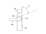
- FIG. 13 to 14 show a fourth example of the embodiment of the present invention corresponding to the above-described configurations (1), (2), and (5).
- the outer peripheral surface of the rotation-side engagement member 11c is a rotation-side engagement surface
- the rotation-side engagement member 11c is shaped like a windmill.
- one circumferential side surface of each of the plurality of rotation-side engagement protrusions 18c and 18c provided on the outer peripheral surface of the rotation-side engagement member 11c is the rotation side.
- the inclined sides 19b and 19b are inclined with respect to the axial direction of the engaging member 11c.
- the restraining side engaging member 12c is disposed near the outer diameter portion of the rotating side engaging member 11c, and can be displaced in the axial direction of the rotating side engaging member 11c.
- the force for displacing the locking-side engaging member 12c in the axial direction is an elastic member such as a compression spring and a solenoid (not shown in FIGS. 13 to 14). And gained by.
- a compression spring or the like among them provides the restraining side engaging member 12c with elasticity in a direction in which the distal end of the restraining side engaging portion 12c is retracted from the periphery of the rotating side engaging member 11c, and the solenoid
- the tip end portion of the restraining side engaging member 12c is displaced toward the periphery of the rotating side engaging member 11c against the elasticity.
- this invention is not limited to embodiment mentioned above, A deformation
- the material, shape, dimension, numerical value, form, number, arrangement location, and the like of each component in the above-described embodiment are arbitrary and are not limited as long as the present invention can be achieved.
- This application is based on a Japanese patent application filed on Mar. 17, 2011 (Japanese Patent Application No. 2011-058748), the contents of which are incorporated herein by reference.
- the present invention is applied to a structure in which not only the parking brake device but also the service brake device is electrically operated.
- the feature of the present invention relates to an improvement in the structure that can operate the parking brake device with the electric motor as a power source and maintain the braking force even after the energization of the electric motor is stopped. Therefore, the present invention can be applied to a structure in which the service brake device is hydraulically operated and only the parking brake device is operated by the electric motor.
- the present invention is not limited to the disc brake device, and can be implemented by a drum brake device.
Landscapes
- Engineering & Computer Science (AREA)
- General Engineering & Computer Science (AREA)
- Mechanical Engineering (AREA)
- Transportation (AREA)
- Braking Arrangements (AREA)
Abstract
Priority Applications (2)
| Application Number | Priority Date | Filing Date | Title |
|---|---|---|---|
| US14/005,431 US20140000992A1 (en) | 2011-03-17 | 2012-03-16 | Electric brake with parking mechanism |
| DE112012001273T DE112012001273T5 (de) | 2011-03-17 | 2012-03-16 | Elektrische Bremse mit Parkmechanismus |
Applications Claiming Priority (2)
| Application Number | Priority Date | Filing Date | Title |
|---|---|---|---|
| JP2011-058748 | 2011-03-17 | ||
| JP2011058748A JP2012193805A (ja) | 2011-03-17 | 2011-03-17 | パーキング機構付電動式ブレーキ装置 |
Publications (1)
| Publication Number | Publication Date |
|---|---|
| WO2012124812A1 true WO2012124812A1 (fr) | 2012-09-20 |
Family
ID=46830871
Family Applications (1)
| Application Number | Title | Priority Date | Filing Date |
|---|---|---|---|
| PCT/JP2012/056939 Ceased WO2012124812A1 (fr) | 2011-03-17 | 2012-03-16 | Dispositif de freinage électrique à mécanisme de stationnement |
Country Status (4)
| Country | Link |
|---|---|
| US (1) | US20140000992A1 (fr) |
| JP (1) | JP2012193805A (fr) |
| DE (1) | DE112012001273T5 (fr) |
| WO (1) | WO2012124812A1 (fr) |
Cited By (2)
| Publication number | Priority date | Publication date | Assignee | Title |
|---|---|---|---|---|
| US20150219172A1 (en) * | 2012-10-25 | 2015-08-06 | Ntn Corporation | Electric brake actuator with parking function |
| CN114688185A (zh) * | 2022-03-25 | 2022-07-01 | 梁为胜 | 一种电控机械制动器锁止机构 |
Families Citing this family (31)
| Publication number | Priority date | Publication date | Assignee | Title |
|---|---|---|---|---|
| EP2715123B1 (fr) * | 2011-05-27 | 2019-01-09 | Seawind Ocean Technology Holding BV | Système de commande d'éolienne ayant un capteur de poussée |
| JP5928723B2 (ja) * | 2012-11-30 | 2016-06-01 | 株式会社アドヴィックス | 車両の電動制動装置 |
| WO2014122547A1 (fr) * | 2013-02-06 | 2014-08-14 | Koninklijke Philips N.V. | Structure de support pour lampe tubulaire |
| JP6335443B2 (ja) * | 2013-06-13 | 2018-05-30 | Ntn株式会社 | 電動式ブレーキ装置 |
| JP6183192B2 (ja) * | 2013-12-05 | 2017-08-23 | 株式会社アドヴィックス | 車両の電動制動装置 |
| JP6160829B2 (ja) * | 2013-12-05 | 2017-07-12 | 株式会社アドヴィックス | 車両の電動制動装置 |
| US9476469B2 (en) * | 2014-01-22 | 2016-10-25 | Akebono Brake Industry Co., Ltd | Electric drum or drum-in-hat park brake |
| CN107076237B (zh) * | 2014-07-08 | 2019-08-02 | 福乐尼·乐姆宝公开有限公司 | 机电制动钳致动器 |
| KR20160011283A (ko) * | 2014-07-21 | 2016-02-01 | 현대모비스 주식회사 | 전자식 주차 브레이크 장치 |
| KR102228030B1 (ko) * | 2014-07-31 | 2021-03-15 | 히다치 아스테모 가부시키가이샤 | 디스크 브레이크 |
| WO2016083945A1 (fr) * | 2014-11-28 | 2016-06-02 | Freni Brembo S.P.A. | Étrier flottant de frein à disque pour freinage de service et de stationnement |
| KR101701211B1 (ko) * | 2015-10-27 | 2017-02-01 | 재단법인대구경북과학기술원 | 전기기계식 브레이크장치 |
| JP6641945B2 (ja) * | 2015-12-04 | 2020-02-05 | 株式会社アドヴィックス | 車両の電動制動装置 |
| KR101836628B1 (ko) * | 2016-05-03 | 2018-03-08 | 현대자동차주식회사 | 전동식 브레이크 장치 및 그 제어 방법 |
| US10518761B2 (en) | 2016-07-01 | 2019-12-31 | Akebono Brake Industry Co., Ltd | Electric park brake with electromagnetic brake |
| EP3296586B1 (fr) * | 2016-09-20 | 2021-05-05 | Ratier-Figeac SAS | Agencement sans arrière d'actionneur |
| US10184536B2 (en) | 2016-09-23 | 2019-01-22 | Akebono Brake Industry Co., Ltd. | Brake piston |
| CN106762768B (zh) * | 2016-12-29 | 2019-03-01 | 深圳兴奇宏科技有限公司 | 风扇刹车结构 |
| US10465758B2 (en) * | 2017-07-26 | 2019-11-05 | Ingersoll-Rand Company | Rotatable shaft with fluid actuated lock piston |
| US20190152460A1 (en) * | 2017-11-22 | 2019-05-23 | GM Global Technology Operations LLC | Electromechanical brake system including a parking lock |
| US11339842B2 (en) | 2019-03-26 | 2022-05-24 | Akebono Brake Industry Co., Ltd. | Brake system with torque distributing assembly |
| FR3117561B1 (fr) * | 2020-12-10 | 2022-11-25 | Safran Landing Systems | Actionneur à frein de parking intégré |
| IT202100012968A1 (it) * | 2021-05-19 | 2022-11-19 | Brembo Spa | Impianto frenante con freni a disco di tipo brake-by-wire, dotato di regolazione dinamica della distanza tra il disco freno e le pastiglie e relativo metodo di regolazione della distanza tra il disco freno e le pastiglie in un impianto frenante di tipo brake-by-wire |
| CN113320507B (zh) * | 2021-06-01 | 2022-09-23 | 华为数字能源技术有限公司 | 一种制动装置及汽车 |
| KR102512309B1 (ko) * | 2021-10-27 | 2023-03-22 | 에이치엘만도 주식회사 | 전자식 브레이크 시스템 및 이를 포함하는 차량 |
| KR102663046B1 (ko) * | 2021-11-26 | 2024-05-03 | 현대모비스 주식회사 | 차량용 브레이크 장치 |
| CN118574757A (zh) * | 2022-05-27 | 2024-08-30 | 曙制动器工业株式会社 | 具有锁定装置的制动系统以及操作制动系统的方法 |
| DE102022123149A1 (de) * | 2022-09-12 | 2024-03-14 | Zf Active Safety Gmbh | Verfahren zum Betrieb einer kraftsensorlosen elektromechanischen Betriebsbremse eines Fahrzeugs und Bremssystem |
| CN117267280A (zh) * | 2023-10-26 | 2023-12-22 | 罗伯特·博世有限公司 | 电子机械制动器 |
| CN117267281A (zh) * | 2023-10-26 | 2023-12-22 | 罗伯特·博世有限公司 | 电子机械制动器 |
| CN118124545A (zh) * | 2024-03-29 | 2024-06-04 | 华为数字能源技术有限公司 | 电子机械制动装置和车辆 |
Citations (6)
| Publication number | Priority date | Publication date | Assignee | Title |
|---|---|---|---|---|
| JP2001524647A (ja) * | 1997-11-21 | 2001-12-04 | コンティネンタル・テーベス・アクチエンゲゼルシヤフト・ウント・コンパニー・オッフェネ・ハンデルスゲゼルシヤフト | 電気機械的に操作可能なディスクブレーキ |
| JP2003329070A (ja) * | 2002-05-15 | 2003-11-19 | Nissin Kogyo Co Ltd | 電気式ディスクブレーキ |
| JP2004263776A (ja) * | 2003-02-28 | 2004-09-24 | Tokico Ltd | 電動ディスクブレーキ装置 |
| JP2005114042A (ja) * | 2003-10-08 | 2005-04-28 | Honda Motor Co Ltd | 電動駐車ブレーキ装置 |
| JP2005186734A (ja) * | 2003-12-25 | 2005-07-14 | Honda Motor Co Ltd | パーキング機構付きブレーキ装置 |
| JP2011202696A (ja) * | 2010-03-24 | 2011-10-13 | Akebono Brake Ind Co Ltd | 電動式パーキング機構付ブレーキ装置 |
Family Cites Families (9)
| Publication number | Priority date | Publication date | Assignee | Title |
|---|---|---|---|---|
| JPH08244580A (ja) | 1995-03-08 | 1996-09-24 | Akebono Brake Res & Dev Center Ltd | キャリパ内組込み型電動ブレーキ装置 |
| JP2003307240A (ja) | 2002-04-15 | 2003-10-31 | Akebono Brake Ind Co Ltd | 電動ブレーキ |
| JP2004169729A (ja) | 2002-11-18 | 2004-06-17 | Akebono Brake Ind Co Ltd | 電動ディスクブレーキ |
| JP4512868B2 (ja) * | 2004-03-31 | 2010-07-28 | 日立オートモティブシステムズ株式会社 | 電動ブレーキ装置 |
| JP4608386B2 (ja) * | 2005-08-04 | 2011-01-12 | 日信工業株式会社 | 車両用電動ディスクブレーキ |
| JP4840598B2 (ja) | 2007-04-27 | 2011-12-21 | 日立オートモティブシステムズ株式会社 | 電動ディスクブレーキ |
| JP5057164B2 (ja) * | 2008-08-29 | 2012-10-24 | 日立オートモティブシステムズ株式会社 | 電動ディスクブレーキ |
| JP5719105B2 (ja) | 2009-09-11 | 2015-05-13 | サンデン株式会社 | 冷凍回路 |
| US8534431B2 (en) * | 2010-07-21 | 2013-09-17 | Warn Industries, Inc. | Face tooth hydraulic piston brake |
-
2011
- 2011-03-17 JP JP2011058748A patent/JP2012193805A/ja not_active Withdrawn
-
2012
- 2012-03-16 DE DE112012001273T patent/DE112012001273T5/de not_active Withdrawn
- 2012-03-16 WO PCT/JP2012/056939 patent/WO2012124812A1/fr not_active Ceased
- 2012-03-16 US US14/005,431 patent/US20140000992A1/en not_active Abandoned
Patent Citations (6)
| Publication number | Priority date | Publication date | Assignee | Title |
|---|---|---|---|---|
| JP2001524647A (ja) * | 1997-11-21 | 2001-12-04 | コンティネンタル・テーベス・アクチエンゲゼルシヤフト・ウント・コンパニー・オッフェネ・ハンデルスゲゼルシヤフト | 電気機械的に操作可能なディスクブレーキ |
| JP2003329070A (ja) * | 2002-05-15 | 2003-11-19 | Nissin Kogyo Co Ltd | 電気式ディスクブレーキ |
| JP2004263776A (ja) * | 2003-02-28 | 2004-09-24 | Tokico Ltd | 電動ディスクブレーキ装置 |
| JP2005114042A (ja) * | 2003-10-08 | 2005-04-28 | Honda Motor Co Ltd | 電動駐車ブレーキ装置 |
| JP2005186734A (ja) * | 2003-12-25 | 2005-07-14 | Honda Motor Co Ltd | パーキング機構付きブレーキ装置 |
| JP2011202696A (ja) * | 2010-03-24 | 2011-10-13 | Akebono Brake Ind Co Ltd | 電動式パーキング機構付ブレーキ装置 |
Cited By (4)
| Publication number | Priority date | Publication date | Assignee | Title |
|---|---|---|---|---|
| US20150219172A1 (en) * | 2012-10-25 | 2015-08-06 | Ntn Corporation | Electric brake actuator with parking function |
| US9605722B2 (en) * | 2012-10-25 | 2017-03-28 | Ntn Corporation | Electric brake actuator with parking function |
| CN114688185A (zh) * | 2022-03-25 | 2022-07-01 | 梁为胜 | 一种电控机械制动器锁止机构 |
| CN114688185B (zh) * | 2022-03-25 | 2024-05-14 | 梁为胜 | 一种电控机械制动器锁止机构 |
Also Published As
| Publication number | Publication date |
|---|---|
| DE112012001273T5 (de) | 2013-12-19 |
| JP2012193805A (ja) | 2012-10-11 |
| US20140000992A1 (en) | 2014-01-02 |
Similar Documents
| Publication | Publication Date | Title |
|---|---|---|
| WO2012124812A1 (fr) | Dispositif de freinage électrique à mécanisme de stationnement | |
| JP5378278B2 (ja) | 電動式パーキング機構付ブレーキ装置 | |
| JP4840598B2 (ja) | 電動ディスクブレーキ | |
| US20120292141A1 (en) | Disc brake apparatus with electric parking mechanism | |
| US12228185B2 (en) | Disk brake | |
| EP3056400B1 (fr) | Dispositif de frein électrique à fonction stationnement | |
| JP5093476B2 (ja) | 電動ディスクブレーキ | |
| US20130186717A1 (en) | Electric linear motion actuator and electric disk brake system | |
| JP2020012554A (ja) | クラッチ装置 | |
| US12241513B2 (en) | Electric brake for vehicle | |
| EP3986758B1 (fr) | Frein de stationnement éléctrique | |
| WO2012124811A1 (fr) | Dispositif de freinage électrique à mécanisme de stationnement | |
| WO2018037848A1 (fr) | Dispositif de frein électrique | |
| JP6267968B2 (ja) | 電動ブレーキ装置 | |
| JP5058189B2 (ja) | 電動式パーキング機構付ディスクブレーキ | |
| JP7257302B2 (ja) | ディスクブレーキ | |
| JP5944674B2 (ja) | 電動式直動アクチュエータおよび電動式ブレーキ装置 | |
| US12509048B2 (en) | Load sensing device for electric brake | |
| JP2014214752A (ja) | 電動式ディスクブレーキ装置 | |
| WO2020009192A1 (fr) | Dispositif d'embrayage | |
| JP2025065811A (ja) | 電動制動装置 | |
| WO2025154377A1 (fr) | Frein électrique | |
| JP2015090157A (ja) | ディスクブレーキ |
Legal Events
| Date | Code | Title | Description |
|---|---|---|---|
| 121 | Ep: the epo has been informed by wipo that ep was designated in this application |
Ref document number: 12757771 Country of ref document: EP Kind code of ref document: A1 |
|
| WWE | Wipo information: entry into national phase |
Ref document number: 14005431 Country of ref document: US |
|
| WWE | Wipo information: entry into national phase |
Ref document number: 1120120012739 Country of ref document: DE Ref document number: 112012001273 Country of ref document: DE |
|
| 122 | Ep: pct application non-entry in european phase |
Ref document number: 12757771 Country of ref document: EP Kind code of ref document: A1 |