WO2012127576A1 - Dispositif de contrôle de périphérie de véhicule - Google Patents
Dispositif de contrôle de périphérie de véhicule Download PDFInfo
- Publication number
- WO2012127576A1 WO2012127576A1 PCT/JP2011/056602 JP2011056602W WO2012127576A1 WO 2012127576 A1 WO2012127576 A1 WO 2012127576A1 JP 2011056602 W JP2011056602 W JP 2011056602W WO 2012127576 A1 WO2012127576 A1 WO 2012127576A1
- Authority
- WO
- WIPO (PCT)
- Prior art keywords
- vehicle
- monitoring device
- images
- periphery monitoring
- display
- Prior art date
- Legal status (The legal status is an assumption and is not a legal conclusion. Google has not performed a legal analysis and makes no representation as to the accuracy of the status listed.)
- Ceased
Links
Images



Classifications
-
- B—PERFORMING OPERATIONS; TRANSPORTING
- B60—VEHICLES IN GENERAL
- B60R—VEHICLES, VEHICLE FITTINGS, OR VEHICLE PARTS, NOT OTHERWISE PROVIDED FOR
- B60R11/00—Arrangements for holding or mounting articles, not otherwise provided for
- B60R11/04—Mounting of cameras operative during drive; Arrangement of controls thereof relative to the vehicle
-
- G—PHYSICS
- G06—COMPUTING OR CALCULATING; COUNTING
- G06T—IMAGE DATA PROCESSING OR GENERATION, IN GENERAL
- G06T3/00—Geometric image transformations in the plane of the image
- G06T3/20—Linear translation of whole images or parts thereof, e.g. panning
-
- G—PHYSICS
- G06—COMPUTING OR CALCULATING; COUNTING
- G06T—IMAGE DATA PROCESSING OR GENERATION, IN GENERAL
- G06T3/00—Geometric image transformations in the plane of the image
- G06T3/40—Scaling of whole images or parts thereof, e.g. expanding or contracting
-
- B—PERFORMING OPERATIONS; TRANSPORTING
- B60—VEHICLES IN GENERAL
- B60R—VEHICLES, VEHICLE FITTINGS, OR VEHICLE PARTS, NOT OTHERWISE PROVIDED FOR
- B60R1/00—Optical viewing arrangements; Real-time viewing arrangements for drivers or passengers using optical image capturing systems, e.g. cameras or video systems specially adapted for use in or on vehicles
- B60R1/20—Real-time viewing arrangements for drivers or passengers using optical image capturing systems, e.g. cameras or video systems specially adapted for use in or on vehicles
- B60R1/22—Real-time viewing arrangements for drivers or passengers using optical image capturing systems, e.g. cameras or video systems specially adapted for use in or on vehicles for viewing an area outside the vehicle, e.g. the exterior of the vehicle
- B60R1/23—Real-time viewing arrangements for drivers or passengers using optical image capturing systems, e.g. cameras or video systems specially adapted for use in or on vehicles for viewing an area outside the vehicle, e.g. the exterior of the vehicle with a predetermined field of view
- B60R1/26—Real-time viewing arrangements for drivers or passengers using optical image capturing systems, e.g. cameras or video systems specially adapted for use in or on vehicles for viewing an area outside the vehicle, e.g. the exterior of the vehicle with a predetermined field of view to the rear of the vehicle
-
- B—PERFORMING OPERATIONS; TRANSPORTING
- B60—VEHICLES IN GENERAL
- B60R—VEHICLES, VEHICLE FITTINGS, OR VEHICLE PARTS, NOT OTHERWISE PROVIDED FOR
- B60R1/00—Optical viewing arrangements; Real-time viewing arrangements for drivers or passengers using optical image capturing systems, e.g. cameras or video systems specially adapted for use in or on vehicles
- B60R1/20—Real-time viewing arrangements for drivers or passengers using optical image capturing systems, e.g. cameras or video systems specially adapted for use in or on vehicles
- B60R1/22—Real-time viewing arrangements for drivers or passengers using optical image capturing systems, e.g. cameras or video systems specially adapted for use in or on vehicles for viewing an area outside the vehicle, e.g. the exterior of the vehicle
- B60R1/28—Real-time viewing arrangements for drivers or passengers using optical image capturing systems, e.g. cameras or video systems specially adapted for use in or on vehicles for viewing an area outside the vehicle, e.g. the exterior of the vehicle with an adjustable field of view
-
- B—PERFORMING OPERATIONS; TRANSPORTING
- B60—VEHICLES IN GENERAL
- B60R—VEHICLES, VEHICLE FITTINGS, OR VEHICLE PARTS, NOT OTHERWISE PROVIDED FOR
- B60R2300/00—Details of viewing arrangements using cameras and displays, specially adapted for use in a vehicle
- B60R2300/30—Details of viewing arrangements using cameras and displays, specially adapted for use in a vehicle characterised by the type of image processing
- B60R2300/306—Details of viewing arrangements using cameras and displays, specially adapted for use in a vehicle characterised by the type of image processing using a re-scaling of images
-
- B—PERFORMING OPERATIONS; TRANSPORTING
- B60—VEHICLES IN GENERAL
- B60R—VEHICLES, VEHICLE FITTINGS, OR VEHICLE PARTS, NOT OTHERWISE PROVIDED FOR
- B60R2300/00—Details of viewing arrangements using cameras and displays, specially adapted for use in a vehicle
- B60R2300/80—Details of viewing arrangements using cameras and displays, specially adapted for use in a vehicle characterised by the intended use of the viewing arrangement
- B60R2300/802—Details of viewing arrangements using cameras and displays, specially adapted for use in a vehicle characterised by the intended use of the viewing arrangement for monitoring and displaying vehicle exterior blind spot views
- B60R2300/8026—Details of viewing arrangements using cameras and displays, specially adapted for use in a vehicle characterised by the intended use of the viewing arrangement for monitoring and displaying vehicle exterior blind spot views in addition to a rear-view mirror system
Definitions
- the present invention relates to a vehicle periphery monitoring device.
- Patent Document 1 Conventionally, as a vehicle periphery monitoring device for monitoring the periphery of a vehicle, for example, one described in Patent Document 1 is known.
- a vehicle periphery monitoring device an image corresponding to a vehicle surrounding environment reflected in a room mirror or a side mirror is displayed on a monitor, and when the vehicle travels at a high speed, the image is enlarged.
- an object of the present invention is to provide a vehicle periphery monitoring device that can enhance the recognition of the vehicle periphery environment.
- a vehicle periphery monitoring device for monitoring the periphery of a vehicle, and includes an imaging unit that captures the periphery of the vehicle and acquires a plurality of peripheral images.
- a display unit that displays a plurality of peripheral images captured by the imaging unit, and an image control unit that controls the plurality of peripheral images displayed on the display unit, and the image control unit includes a plurality of peripherals displayed on the display unit The distance between images is variable.
- this periphery monitoring device by changing the distance between a plurality of surrounding images, it is possible to enhance the sensory understanding of the vehicle surrounding environment by the driver and to enhance the recognition of the vehicle surrounding environment.
- the image control unit varies the distance between a plurality of surrounding images according to the traveling state of the vehicle. In this case, the recognizability of the environment around the vehicle suitable for the traveling state of the vehicle can be enhanced.
- the image control unit varies the distance between the regions of the plurality of peripheral images according to the angles of view of the plurality of peripheral images.
- the recognizability of the surrounding environment of the vehicle can be enhanced in accordance with changes in the angle of view in the surrounding image, such as a wide angle and a narrow angle.
- the image control unit varies the view angle balance of the plurality of surrounding images according to the turning situation of the vehicle. In this case, it is possible to enhance monitoring in the direction in which the entrainment is expected due to the inner ring difference or the outer ring difference.
- the plurality of surrounding images may correspond to a pair of vehicle surrounding environments reflected in the right and left side mirrors.
- the back monitoring corresponding to a side mirror can be easily performed by a display part.
- FIG. 1 is a schematic configuration diagram showing a vehicle periphery monitoring device according to an embodiment of the present invention.
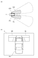
- (A) is an overhead view showing a vehicle for explaining an example of the operation in the vehicle periphery monitoring device of FIG. 1, and (b) shows a display for explaining an example of the operation in the vehicle periphery monitoring device of FIG.
- FIG. (A) is an overhead view showing a vehicle for explaining another example of the operation in the vehicle periphery monitoring device of FIG. 1, and (b) is for explaining another example of the operation in the vehicle periphery monitoring device of FIG.
- FIG. (A) is a bird's-eye view showing a vehicle for explaining yet another example of the operation in the vehicle periphery monitoring device of FIG. 1, and (b) is a further example of the operation in the vehicle periphery monitoring device of FIG. It is a figure which shows the display for doing.
- FIG. 1 is a schematic configuration diagram showing a vehicle periphery monitoring device according to an embodiment of the present invention
- FIGS. 2 to 4 are explanatory diagrams showing examples of operations in the vehicle periphery monitoring device of FIG.
- the vehicle periphery monitoring device 1 according to the present embodiment is mounted on a vehicle V such as an automobile and is for monitoring the periphery of the vehicle.
- the braking device 1 includes an imaging device (imaging unit) 2, a display (display unit) 3, and an image control device (image control unit) 4.
- the imaging device 2 captures the periphery of the vehicle V and acquires a plurality of peripheral images G.
- This imaging device 2 includes a right camera 2R and a left camera 2L.
- the right camera 2R captures a peripheral image GR on the right rear side of the vehicle, as corresponding to the vehicle peripheral environment reflected on the right side mirror 21R.
- the right camera 2R is attached to the right side of the vehicle (for example, the right side mirror 21R) so as to face rearward.
- the left camera 2L captures a peripheral image GL on the left rear side of the vehicle as corresponding to the vehicle peripheral environment reflected on the left side mirror 21L.
- the left camera 2L is attached to the left side of the vehicle (for example, the left side mirror 21L) so as to face rearward.
- the right camera 2R and the left camera 2L are connected to the image control device 4.
- the right camera 2R and the left camera 2L output the captured peripheral images GR and GL to the image control device 4.
- the image control device 4 varies the angle of view (the imaging range expressed in angle) and the magnification ratio of the plurality of peripheral images GR and GL to be captured.
- Various cameras can be used as the right camera 2R and the left camera 2L, and are not particularly limited.
- the display 3 displays the peripheral images GR and GL captured by the imaging device 2.
- the display 3 is connected to the image control device 4.
- the display 3 here displays the surrounding images GR and GL and the vehicle image GV corresponding to the vehicle V based on the input from the image control device 4.
- Various displays (monitors) can be used as the display 3 and are not particularly limited.
- the image control device 4 controls the peripheral images GR and GL displayed on the display 3.
- the image control device 4 is configured by an ECU (Electronic Control Unit) including a CPU, a ROM, a RAM, and the like, for example.
- the image control device 4 includes a vehicle travel state recognition unit 4a for recognizing the travel state of the vehicle V, and an image display range calculation unit 4b that calculates an image display range.
- the vehicle travel state recognition unit 4a is connected to the steering sensor 11, the blinker sensor 12, the wiper sensor 13, the vehicle speed sensor 14, the shift sensor 15, and the light sensor 16, and the vehicle V travels based on sensor information input from these. Recognize the situation.
- the steering sensor 11 detects the steering situation.
- the blinker sensor 12 detects the operating state of the blinker.
- the wiper sensor 13 detects the operation status of the wiper.
- the vehicle speed sensor 14 detects the speed of the vehicle V.
- the shift sensor 15 detects a shift (transmission gear) situation of the vehicle V.
- the light sensor 16 detects the operating state of the headlight of the vehicle V.
- the image display range calculation unit 4b varies the size and position of the vehicle image GV and the surrounding images GR and GL on the display 3, the angle of view and the enlargement ratio of the surrounding images GR and GL. Further, the image display range calculation unit 4b changes at least the distance D between the plurality of peripheral images GR and GL displayed on the display 3 (details will be described later).
- the traveling state of the vehicle V is recognized based on the inputs from the sensors 11 to 16 by the vehicle traveling state recognition unit 4a.
- the vehicle V travels in the city, traveling in the city, traveling at a high speed with a narrow effective field of view, turning right and left at the intersection, etc. It is recognized whether or not the vehicle is turning traveling (rolling traveling) or parking traveling for parking. It is recognized from the input of the wiper sensor 13 whether or not the vehicle travel is rainy. From the input of the light sensor 16, it is recognized whether the vehicle travel is daytime travel or night travel.
- the image display range calculation unit 4b performs the following operation. That is, as shown in FIGS. 2A and 2B, the peripheral images GR and GL having a high magnification and a narrow angle of view (narrow angle), that is, the left and right rear sides of the vehicle V are narrow areas 10R and 10L.
- the displayed peripheral images GR and GL are displayed on the display 3 side by side at a predetermined distance D apart from each other.
- the vehicle image GV is displayed large on the display 3.
- a peripheral image GR with a high magnification and a narrow angle of view is displayed at a position corresponding to the right rear of the vehicle image GV.
- a peripheral image GL with a high magnification and a narrow angle of view is displayed at a position corresponding to the left rear of the vehicle image GV.
- the distance D between the peripheral images GR and GL is set to a distance D1 that is larger than distances D2 and D3 described later.
- the plurality of peripheral images GR and GL are displayed separated by a distance D1 so as to be arranged in the left-right direction with a large gap.
- the image display range calculation unit 4b performs the following operation. That is, as shown in FIGS. 3A and 3B, the peripheral images GR and GL having a low magnification and a wide angle of view (wide angle), that is, the left and right rear sides of the vehicle V are displayed in a wide range 10R and 10L. The surrounding images GR and GL are displayed side by side on the display 3 with a predetermined distance D apart.
- the vehicle image GV is displayed small on the display 3.
- a peripheral image GR with a low magnification and a wide angle of view is displayed at a position corresponding to the right rear of the vehicle image GV.
- a peripheral image GL having a low magnification and a wide angle of view is displayed at a position corresponding to the left rear of the vehicle image GV.
- the distance D between the peripheral images GR and GL is set to a distance D2 smaller than the distance D1 and a distance D3 described later.
- the plurality of peripheral images GR and GL are displayed separated by a distance D2 so as to be arranged in the left-right direction with a small gap.
- the image display range calculation unit 4b executes the following operation. That is, as shown in FIGS. 4A and 4B, the peripheral images GR and GL having the same magnification and different view angles, that is, the left and right rear sides of the vehicle V are displayed in different ranges 10R and 10L. The surrounding images GR and GL are displayed side by side on the display 3 with a predetermined distance D apart.
- the vehicle image GV is displayed in a normal size at a position on the display 3 that is closer to the left side from the center in the left-right direction.
- a peripheral image GR with a normal magnification and a narrow angle of view is displayed at a position corresponding to the right rear of the vehicle image GV.
- a peripheral image GL having a normal magnification and a wide angle of view is displayed at a position corresponding to the left rear of the vehicle image GV.
- one of the peripheral images GR and GL on the side where the inner wheel difference or the outer wheel difference of the vehicle V is generated is displayed in a wide range.
- a distance D between the peripheral images GR and GL is set to a distance D2 that is smaller than the distance D1 and larger than the distance D3.
- the driver can sensibly understand the vehicle surrounding environment by changing the distance D between the surrounding images GR and GL that strongly affects the recognition of the vehicle surrounding environment. It is possible to improve the recognition of the environment around the vehicle. That is, in this embodiment, when displaying the vehicle rear side with the plurality of cameras 2a and 2b, by determining the distance D between the peripheral images GR and GL by the cameras 2a and 2b in consideration of the vehicle V, It becomes possible to easily recognize the environment around the vehicle.
- the distance D between the peripheral images GR and GL is varied according to the traveling state of the vehicle V.
- working condition of the vehicle V can be improved.
- the surrounding environment of the vehicle can be recognized in consideration of the traveling state of the vehicle V, and erroneous recognition of the surrounding environment of the vehicle can be suppressed.
- the distance D between the peripheral images GR and GL is varied according to the angle of view and the enlargement ratio of the peripheral images GR and GL.
- the peripheral images GR and GL correspond to (correspond to) a pair of vehicle surrounding environments reflected on the right and left side mirrors 21R and 21L, and thus correspond to the side mirrors 21R and 21L.
- the rear monitoring can be easily performed on the display 3.
- the peripheral images GR and GL are enlarged and displayed, and the distance D between the peripheral images GR and GL is set to a wide distance D1.
- the peripheral images GR and GL are enlarged and displayed, and the distance D between the peripheral images GR and GL is set to a wide distance D1.
- the vehicle image GV when turning or traveling at a high speed, the vehicle image GV is reduced, the enlargement ratio of the peripheral images GR and GL is reduced, and the vehicle periphery is displayed widely.
- a distance D between the images GR and GL is a narrow distance D2.
- the angle of view of each of the peripheral images GR and GL is changed in consideration of the inner wheel difference or the outer wheel difference. (The display range is shifted.) That is, the view angle balance of the peripheral images GR and GL is varied according to the turning situation of the vehicle V. As a result, it becomes possible to efficiently recognize information necessary for turning, and it is possible to strengthen monitoring of the direction in which the entrainment is expected due to the inner ring difference or the outer ring difference. In this case, since the enlargement ratios of the peripheral images GR and GL are equal to each other, even if the angles of view of the peripheral images GR and GL are different from each other, the uncomfortable feeling can be suppressed.
- a display space on the display 3 may be secured by not displaying the vehicle image GV on the display 3, and in this case, other information such as alerting and navigation information can be suitably displayed.
- other information such as alerting and navigation information can be suitably displayed.
- SYMBOLS 1 Vehicle periphery monitoring apparatus, 2 ... Imaging device (imaging part), 3 ... Display (display part), 4 ... Image control apparatus (image control part), 21R, 21L ... Side mirror, D, D1, D2, D3 ... Distance between peripheral images, G, GR, GL ... peripheral image, V ... vehicle.
Landscapes
- Engineering & Computer Science (AREA)
- Physics & Mathematics (AREA)
- General Physics & Mathematics (AREA)
- Theoretical Computer Science (AREA)
- Mechanical Engineering (AREA)
- Multimedia (AREA)
- Closed-Circuit Television Systems (AREA)
- Fittings On The Vehicle Exterior For Carrying Loads, And Devices For Holding Or Mounting Articles (AREA)
Abstract
Priority Applications (5)
| Application Number | Priority Date | Filing Date | Title |
|---|---|---|---|
| PCT/JP2011/056602 WO2012127576A1 (fr) | 2011-03-18 | 2011-03-18 | Dispositif de contrôle de périphérie de véhicule |
| JP2012513116A JP5273300B2 (ja) | 2011-03-18 | 2011-03-18 | 車両周辺監視装置 |
| EP11837287.9A EP2687408B1 (fr) | 2011-03-18 | 2011-03-18 | Dispositif de contrôle de périphérie de véhicule |
| US13/508,861 US8768575B2 (en) | 2011-03-18 | 2011-03-18 | Vehicle periphery monitoring device |
| CN201180026304.XA CN103282236B (zh) | 2011-03-18 | 2011-03-18 | 车辆周边监视装置 |
Applications Claiming Priority (1)
| Application Number | Priority Date | Filing Date | Title |
|---|---|---|---|
| PCT/JP2011/056602 WO2012127576A1 (fr) | 2011-03-18 | 2011-03-18 | Dispositif de contrôle de périphérie de véhicule |
Publications (1)
| Publication Number | Publication Date |
|---|---|
| WO2012127576A1 true WO2012127576A1 (fr) | 2012-09-27 |
Family
ID=46878773
Family Applications (1)
| Application Number | Title | Priority Date | Filing Date |
|---|---|---|---|
| PCT/JP2011/056602 Ceased WO2012127576A1 (fr) | 2011-03-18 | 2011-03-18 | Dispositif de contrôle de périphérie de véhicule |
Country Status (5)
| Country | Link |
|---|---|
| US (1) | US8768575B2 (fr) |
| EP (1) | EP2687408B1 (fr) |
| JP (1) | JP5273300B2 (fr) |
| CN (1) | CN103282236B (fr) |
| WO (1) | WO2012127576A1 (fr) |
Cited By (3)
| Publication number | Priority date | Publication date | Assignee | Title |
|---|---|---|---|---|
| JP2017212482A (ja) * | 2016-05-23 | 2017-11-30 | マツダ株式会社 | 電子ミラー装置 |
| JP2017212481A (ja) * | 2016-05-23 | 2017-11-30 | マツダ株式会社 | 電子ミラー装置 |
| EP2954120B1 (fr) * | 2013-02-06 | 2019-03-20 | Volvo Construction Equipment Germany GmbH | Engin de chantier comportant un dispositif de surveillance |
Families Citing this family (8)
| Publication number | Priority date | Publication date | Assignee | Title |
|---|---|---|---|---|
| KR100959347B1 (ko) * | 2010-02-24 | 2010-05-20 | 조성호 | 자동차의 좌우후방 시야확보 장치 |
| US9990556B2 (en) * | 2012-07-27 | 2018-06-05 | Kyocera Corporation | Image processing apparatus, imaging apparatus, movable object, program, and region setting method |
| JP5991387B2 (ja) * | 2013-02-08 | 2016-09-14 | トヨタ自動車株式会社 | 表示装置 |
| FR3021600B1 (fr) * | 2014-05-27 | 2017-10-20 | Valeo Comfort & Driving Assistance | Systeme d'affichage pour vehicule automobile |
| JP6582392B2 (ja) * | 2014-11-05 | 2019-10-02 | 株式会社デンソー | 車載周辺物体報知システム、物体報知システム、報知制御装置 |
| JP6041005B2 (ja) * | 2015-02-10 | 2016-12-07 | 株式会社Jvcケンウッド | 表示制御装置及び表示システム |
| JP2019193031A (ja) * | 2018-04-23 | 2019-10-31 | シャープ株式会社 | 車両周辺表示装置 |
| JP2025136614A (ja) * | 2024-03-07 | 2025-09-19 | トヨタ自動車株式会社 | 表示制御装置、表示制御方法、及び表示制御プログラム |
Citations (4)
| Publication number | Priority date | Publication date | Assignee | Title |
|---|---|---|---|---|
| JPH06227318A (ja) * | 1993-02-08 | 1994-08-16 | Hitachi Ltd | 車両の後方モニタ装置及び方法 |
| JPH10257482A (ja) * | 1997-03-13 | 1998-09-25 | Nissan Motor Co Ltd | 車両周辺状況表示装置 |
| JP2003081014A (ja) * | 2001-09-14 | 2003-03-19 | Auto Network Gijutsu Kenkyusho:Kk | 車両周辺監視装置 |
| JP2010188902A (ja) * | 2009-02-19 | 2010-09-02 | Denso Corp | 車外映像表示システムおよび車両 |
Family Cites Families (8)
| Publication number | Priority date | Publication date | Assignee | Title |
|---|---|---|---|---|
| EP1179958B1 (fr) * | 1999-04-16 | 2012-08-08 | Panasonic Corporation | Dispositif de traitement d'images et systeme de surveillance |
| JP3298851B2 (ja) * | 1999-08-18 | 2002-07-08 | 松下電器産業株式会社 | 多機能車載カメラシステムと多機能車載カメラの画像表示方法 |
| US7576767B2 (en) * | 2004-07-26 | 2009-08-18 | Geo Semiconductors Inc. | Panoramic vision system and method |
| JP4566822B2 (ja) * | 2005-05-24 | 2010-10-20 | 本田技研工業株式会社 | 車両用画像表示装置 |
| JP2008004990A (ja) | 2006-06-20 | 2008-01-10 | Nissan Motor Co Ltd | 車両用表示制御装置 |
| JP4855158B2 (ja) | 2006-07-05 | 2012-01-18 | 本田技研工業株式会社 | 運転支援装置 |
| JP5320970B2 (ja) | 2008-10-15 | 2013-10-23 | 日産自動車株式会社 | 車両用表示装置および表示方法 |
| US8502860B2 (en) * | 2009-09-29 | 2013-08-06 | Toyota Motor Engineering & Manufacturing North America (Tema) | Electronic control system, electronic control unit and associated methodology of adapting 3D panoramic views of vehicle surroundings by predicting driver intent |
-
2011
- 2011-03-18 US US13/508,861 patent/US8768575B2/en not_active Expired - Fee Related
- 2011-03-18 WO PCT/JP2011/056602 patent/WO2012127576A1/fr not_active Ceased
- 2011-03-18 EP EP11837287.9A patent/EP2687408B1/fr not_active Not-in-force
- 2011-03-18 CN CN201180026304.XA patent/CN103282236B/zh not_active Expired - Fee Related
- 2011-03-18 JP JP2012513116A patent/JP5273300B2/ja not_active Expired - Fee Related
Patent Citations (4)
| Publication number | Priority date | Publication date | Assignee | Title |
|---|---|---|---|---|
| JPH06227318A (ja) * | 1993-02-08 | 1994-08-16 | Hitachi Ltd | 車両の後方モニタ装置及び方法 |
| JPH10257482A (ja) * | 1997-03-13 | 1998-09-25 | Nissan Motor Co Ltd | 車両周辺状況表示装置 |
| JP2003081014A (ja) * | 2001-09-14 | 2003-03-19 | Auto Network Gijutsu Kenkyusho:Kk | 車両周辺監視装置 |
| JP2010188902A (ja) * | 2009-02-19 | 2010-09-02 | Denso Corp | 車外映像表示システムおよび車両 |
Non-Patent Citations (1)
| Title |
|---|
| See also references of EP2687408A4 * |
Cited By (3)
| Publication number | Priority date | Publication date | Assignee | Title |
|---|---|---|---|---|
| EP2954120B1 (fr) * | 2013-02-06 | 2019-03-20 | Volvo Construction Equipment Germany GmbH | Engin de chantier comportant un dispositif de surveillance |
| JP2017212482A (ja) * | 2016-05-23 | 2017-11-30 | マツダ株式会社 | 電子ミラー装置 |
| JP2017212481A (ja) * | 2016-05-23 | 2017-11-30 | マツダ株式会社 | 電子ミラー装置 |
Also Published As
| Publication number | Publication date |
|---|---|
| JP5273300B2 (ja) | 2013-08-28 |
| EP2687408A1 (fr) | 2014-01-22 |
| US8768575B2 (en) | 2014-07-01 |
| EP2687408A4 (fr) | 2014-07-16 |
| EP2687408B1 (fr) | 2017-06-14 |
| CN103282236B (zh) | 2014-04-23 |
| US20140012464A1 (en) | 2014-01-09 |
| CN103282236A (zh) | 2013-09-04 |
| JPWO2012127576A1 (ja) | 2014-07-24 |
Similar Documents
| Publication | Publication Date | Title |
|---|---|---|
| JP5273300B2 (ja) | 車両周辺監視装置 | |
| US11052823B2 (en) | Vehicle rear monitoring system | |
| JP6346614B2 (ja) | 情報表示システム | |
| US9589194B2 (en) | Driving assistance device and image processing program | |
| JP4943367B2 (ja) | 車両用情報表示装置 | |
| US20230001985A1 (en) | Display device for a vehicle | |
| JP6448714B2 (ja) | 情報表示システム | |
| WO2018180142A1 (fr) | Dispositif d'affichage d'image pour véhicule et procédé de traitement d'image | |
| JP6166188B2 (ja) | 撮像システム、および撮像システムの制御方法 | |
| JP5073703B2 (ja) | 車両用表示装置 | |
| JP2011211432A (ja) | 車載用撮像装置 | |
| JP6367081B2 (ja) | 走行支援装置、走行支援プログラムおよび走行支援方法 | |
| JP2006035995A (ja) | 車両用表示装置 | |
| JP6127391B2 (ja) | 車両周辺視認装置 | |
| JP5831331B2 (ja) | 車両の後側方撮影装置 | |
| JP2006343545A (ja) | カメラ装置及び車両周辺監視装置 | |
| JP6704645B2 (ja) | 車両用表示システム | |
| WO2019058581A1 (fr) | Dispositif d'aide à la conduite | |
| JP6815687B2 (ja) | 車両用表示システム | |
| WO2024257338A1 (fr) | Dispositif de traitement d'image, procédé de commande de dispositif de traitement d'image, véhicule, programme et support de stockage | |
| WO2022209070A1 (fr) | Système d'aide à la conduite et véhicule | |
| JP2013035388A (ja) | 車両運転支援装置 | |
| WO2014054198A1 (fr) | Dispositif de détection de direction de mouvement de véhicule |
Legal Events
| Date | Code | Title | Description |
|---|---|---|---|
| ENP | Entry into the national phase |
Ref document number: 2012513116 Country of ref document: JP Kind code of ref document: A |
|
| REEP | Request for entry into the european phase |
Ref document number: 2011837287 Country of ref document: EP |
|
| WWE | Wipo information: entry into national phase |
Ref document number: 2011837287 Country of ref document: EP |
|
| WWE | Wipo information: entry into national phase |
Ref document number: 13508861 Country of ref document: US |
|
| 121 | Ep: the epo has been informed by wipo that ep was designated in this application |
Ref document number: 11837287 Country of ref document: EP Kind code of ref document: A1 |
|
| NENP | Non-entry into the national phase |
Ref country code: DE |