WO2012127613A1 - Nacelle mobile et appareil ascenseur - Google Patents
Nacelle mobile et appareil ascenseur Download PDFInfo
- Publication number
- WO2012127613A1 WO2012127613A1 PCT/JP2011/056799 JP2011056799W WO2012127613A1 WO 2012127613 A1 WO2012127613 A1 WO 2012127613A1 JP 2011056799 W JP2011056799 W JP 2011056799W WO 2012127613 A1 WO2012127613 A1 WO 2012127613A1
- Authority
- WO
- WIPO (PCT)
- Prior art keywords
- plate
- ceiling
- ion generator
- car
- inner frame
- Prior art date
- Legal status (The legal status is an assumption and is not a legal conclusion. Google has not performed a legal analysis and makes no representation as to the accuracy of the status listed.)
- Ceased
Links
Images



Classifications
-
- B—PERFORMING OPERATIONS; TRANSPORTING
- B66—HOISTING; LIFTING; HAULING
- B66B—ELEVATORS; ESCALATORS OR MOVING WALKWAYS
- B66B11/00—Main component parts of lifts in, or associated with, buildings or other structures
- B66B11/02—Cages, i.e. cars
- B66B11/0226—Constructional features, e.g. walls assembly, decorative panels, comfort equipment, thermal or sound insulation
Definitions
- the present invention relates to a car and an elevator apparatus to which an ion generator is attached.
- an ion generator is used in combination with a device having an air blowing function such as an air conditioner or an air purifier, and the air blowing unit such as a fan and the driving unit such as a motor for driving the fan are omitted to reduce the size and make it easy to use.
- the air blowing unit such as a fan and the driving unit such as a motor for driving the fan are omitted to reduce the size and make it easy to use.
- proposals for cost reduction For example, there is one in which an ion generator and a ventilator are connected by a flexible tube, and ions are sent into a car using a fan of the ventilator (see, for example, Patent Document 1).
- Patent Document 1 it is not necessary to install a deodorizing device (ion generator) on the side of a fan installed on a cab by a flexible hose, and the location of the installation location of the deodorizing device (ion generator) is not required. It seems that the degree of freedom can be improved.
- the deodorizer (ion generator) has a problem of interference with the optional equipment and the fan depending on the size of the elevator and the position of the optional equipment, and can be installed at an arbitrary position. Therefore, there is a possibility that problems such as reviewing the height dimension on the car will occur.
- this structure is a structure in which a deodorizer (ion generator) is installed on the cab, but maintenance personnel must be in the cab when checking or replacing the deodorizer (ion generator). Therefore, there is a problem that the time required for such maintenance becomes long and the use time limit of the elevator becomes long.
- a deodorizer ion generator
- the present invention has been made in view of the above problems, and has a mounting structure that does not easily interfere with other devices when the ion generator is mounted, and the degree of freedom of the mounting position of the ion generator is not required without changing the size of the car. It is an object of the present invention to provide a car and an elevator device that can improve the vehicle.
- a car and an elevator apparatus include a car floor, a side plate standing around the car floor, an outer ceiling plate provided on the side plate, A ceiling inner frame provided below the ceiling plate so as to face the side plate, an inner ceiling portion provided on the lower side of the ceiling inner frame, and a blower fan provided above the outer ceiling plate
- the air from the blower fan is supplied into the car through a space formed by the outer ceiling plate, the ceiling inner frame, and the side plate, and the ion generator is formed into a plate body larger than the outer shape of the ion generator.
- the ion generator is positioned in the space from the back side of the ceiling inner frame with respect to the space through a notch hole that is fixed and is larger than the outer shape of the ion generator provided on the ceiling inner frame and smaller than the plate. Let it hard Characterized in that it was.
- a car and an elevator apparatus that have an attachment structure that hardly interferes with other equipment and can improve the degree of freedom of the ion generator installation position without requiring a change in the size of the car. Can provide.
- FIG. 1 is a front sectional view showing an outline of an elevator apparatus according to an embodiment of the present invention.
- An elevator apparatus 100 shown in FIG. 1 includes a car 3 and a counterweight 4 that are guided by guide rails 2 laid in the hoistway 1 to move up and down the hoistway 1, and a main rope 5 that connects these in a slidable manner.
- a hoisting machine 6 as a driving device for driving the main rope 5 by winding it around the top of the hoistway 1.
- the position where the hoisting machine 6 is provided is not limited to this, and the hoisting machine 6 may be arranged at various positions by roping the main rope 5 such as being arranged inside the hoistway 1 of the elevator apparatus not provided with a machine room. Is possible.
- the car 3 includes a car frame 7 and a car room 8.
- FIG. 2 is a perspective view showing the outline of the cab 8.
- the structure of the car room 8 includes a ceiling 9, a car floor 10, and a side plate 11 erected around the car floor 10, as shown in FIG.
- FIG. 3 is a longitudinal sectional view of the cab 8.
- the ceiling 9 is composed of an outer ceiling plate 12, and the outer ceiling plate 12 is provided on the side plate 11.
- the ceiling inner frame 13 is provided below the outer ceiling plate 12 so as to face the side plate 11, and an inner ceiling portion 21 is provided below the ceiling inner frame 13.
- the car 3 in this embodiment has a double ceiling structure.
- the outer ceiling plate 12 above the space 25 formed by the outer ceiling plate 12, the ceiling inner frame 13, and the side plate 11 is provided with a ventilation opening, and the ventilation fan 14 is provided so as to match the ventilation opening. That is, the blower fan 14 is provided above the outer ceiling plate, and the wind from the blower fan 14 is supplied into the car cab 8 through the space 25.
- the ion generator unit 19 is provided in the space 25.
- FIG. 4 is a front sectional view showing an outline of the ion generator unit 19.
- the ion generator 15 is fixed to the cover 16 that is a cover body of the ion generator 15 with a bolt.
- the cover 16 is larger than the outer shape of the ion generator 15 and has a shape covering the periphery except for one surface of the ion generator 15.
- the cover 16 is provided with a discharge port cutout hole having a diameter larger than that of the ion discharge port 17 for discharging ions generated by the ion generation device 15, and the ion generation device 15 is provided with ions from the discharge port cutout hole.
- the discharge port 17 is fixed to the cover 16 in a state where the discharge port 17 is exposed to the outside of the cover 16.
- one surface of the ion generator 15 that is not covered with the cover 16 is covered with a mounting plate 18 that is a plate body larger than the outer shape of the cover 16, and the mounting plate 18 and the cover 16 are fixed with bolts.
- the ion generator 15 in this embodiment is being fixed to the attachment plate 18 which is a board larger than the external shape of the ion generator 15.
- FIG. In this state, the ion generator unit 19 is configured.
- the periphery of the ion generating device 15 is covered by the case constituted by the cover 16 and the mounting plate 18, foreign matters and the like are prevented from being mixed into the ion generating device 15, thereby extending the life. It is possible.
- the space 25 is devised so that the members surrounding the space 25 and those arranged in the space 25 are not conspicuous in order to improve the design of the interior of the car. Therefore, the color is unified by the member surrounding the space 25 and the member arranged inside, but the workability of the ion generator 15 and the like deteriorates when the color of the appearance is changed for each applied elevator device. End up.
- the color can be unified by the cover 16, and the ion generator 15 and the like can be unified by the member surrounding the space 25 for each elevator device to which the ion generator 15 is applied. Becomes easier and the design can be further improved.
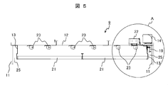
- FIG. 5 is a front sectional view showing the outline of the ceiling 9 of the cab 8.
- the power supply device 22 of the ion generator 15 is disposed above the outer ceiling plate 12 and in the vicinity of the blower fan 14.
- An illuminating device 23 in a car room is provided in a space surrounded by the ceiling inner frame 13 and the inner ceiling portion 21 on the lower surface of the outer ceiling plate 14.
- the inner ceiling portion 21 is configured by an acrylic plate or the like that covers the lighting device 23 and is held at the lower end of the ceiling inner frame 13.
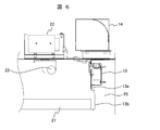
- FIG. 6 is an enlarged view of part A in FIG.
- the ceiling inner frame 13 in the present embodiment is composed of a hanging member 13a hanging from the ceiling portion and an inner ceiling portion holding member 13b attached to the lower part of the hanging member 13a.
- the inner ceiling portion 21 can be removed by maintenance or replacement of the lighting device 23.
- the hanging member 13a is provided with a notch hole that is larger than the outer shape of the ion generator 15 and the cover 16 and smaller than the mounting plate 18, and the back surface side of the space 25 of the ceiling inner frame 13 through the notch hole, that is,
- the ion generator 15 is positioned in the space 25 from the surface on which the inner ceiling portion 21 is provided, the mounting plate 18 and the peripheral portion of the notch hole of the hanging member 13a are overlapped, and this overlapping portion is tightened with bolts or the like.
- the ion generator unit 19 is fixed to the ceiling inner frame 13.
- the notch hole provided in the ceiling inner frame 13 can be provided at an arbitrary position of the ceiling inner frame 13, and the ion generator 15 is disposed between the ceiling inner frame 13 and the side plate 11 through the notch hole. Since the ion generator unit 19 can be attached to the ceiling inner frame 13 by being exposed, the degree of freedom of the attachment location is improved.
- the ion generator 15 is attached from the space surrounded by the outer ceiling plate 12 provided with the illumination device 23, the ceiling inner frame 13, and the inner ceiling portion 21, but the attachment plate 18 is The ceiling inner frame 13 is made sufficiently larger than the notch hole, and the mounting plate 18 closes the aforementioned notch hole, thereby preventing light leakage of ceiling lighting from the notch hole and entering the space 25. It is possible to prevent the deterioration of design properties due to light leakage.
- the mounting structure described above in order to access the ion generator 15, it is not necessary for maintenance personnel or workers to get into the upper portion of the ceiling 9, and the inner ceiling portion 21 is removed and the ion generator 15 is removed from the cab 8. Can be accessed. And by making only the ion generator unit 19 detachable from the inside of the car room 8 by this, the inspection and replacement work of the ion generator 15 is simplified, and the use stop time of the elevator at the time of the inspection and replacement work is reduced. It can be shortened.
- the ion generator unit 19 can be installed arbitrarily on the ceiling inner frame 13, the cage can be installed on an air passage through which the air blown from the blower fan 14 blows into the interior of the car room. Since ions are supplied satisfactorily in the room, it is preferable to install them close to such a positional relationship.
- FIG. 7 is a front perspective view showing an attachment state of the ion generator unit 19.
- a notch is provided in the mounting plate 18 as an inspection window 24 (indicated by a two-dot chain line in FIG. 7).
- An inspection window closing member 20 that covers the inspection window 24 so as to be freely opened and closed is provided.
- the inspection window 24 is provided in the vicinity of the periodic inspection portion of the ion generator 15, and the inspection window closing plate 20 is fixed with screws.
- the periodic inspection unit it is preferable to use a part with the highest failure frequency or a member with the shortest operation compensation time as the ion generator 15, and in this embodiment, it is possible to check the operation of the cooling fan with the shortest operating life.
- An inspection window 24 is provided.
- the shape of the fixing hole 26 for fixing the inspection window closing plate 20 with a screw is a Dharma shape in which a hole diameter suitable for screw fixing and a hole diameter larger than the screw head are continuous.
- the inspection window closing plate 20 can be easily detached by lifting the inspection window closing plate 20 upward by slightly loosening the screw without completely removing the screw. Inspection can be carried out, the inspection work of the ion generator 15 can be simplified, and the use stop time of the elevator at the time of inspection can be shortened.
- the configuration in which the inspection window is provided on the mounting plate 18 eliminates the need to perform the work of removing the mounting plate 18 from the ceiling inner frame 13 and performing the inspection every time inspection is performed. Significant shortening is possible.
- the ion generator can be used without changing the height on the car regardless of the size of the elevator or the position of the additional specification device. It is possible to obtain an elevator apparatus that can shorten the use stop time of the elevator when the ion generator is inspected or replaced.
- the ion generating device 15 is covered with the case 16 and the ion generating device 15 is attached to the mounting plate 18 via the case 16.
- the structure may be such that the ion generator 15 is directly attached to the mounting plate 18.
- the boundary between the space 25 and the car room 8 is opened, but this may be closed with a plate material or the like.
- a configuration may be employed in which a blow-out port through which the air blown from the blower fan 14 blows out from the closed space, or a plurality of blow-out holes are provided in a plate material that closes the boundary.
- a notch is provided as an inspection window, and an inspection window closing member 20 is provided for closing the inspection window.
- the cover 16 and the mounting plate 18 may be made of a transparent member so as to be visible.
- the inspection plate is provided on the mounting plate 18, but a configuration provided on the cover 16 may be employed. Even with such a configuration, it is possible to remove the mounting plate 18 and inspect from the inspection window of the cover 16, thereby shortening the time for inspection.
- the mode in which the inspection window closing plate 20 is fixed by screws is described as an example.
- the present invention is not limited to this.
- a hinge is provided at the lower end of the inspection window closing plate 20 and the upper end is Is configured to be detachably opened and closed with a magnet, configured to be opened and closed with a lever or the like instead of a magnet, a sliding groove for holding the right and left peripheral edges of the inspection window closing plate 20 of the mounting plate 18 is provided, and an inspection window is provided in the sliding groove
- a hinge is provided at the lower end of the inspection window closing plate 20 and the upper end is Is configured to be detachably opened and closed with a magnet, configured to be opened and closed with a lever or the like instead of a magnet
- a sliding groove for holding the right and left peripheral edges of the inspection window closing plate 20 of the mounting plate 18 is provided, and an inspection window is provided in the sliding groove
- Various forms such as a configuration in which the closing plate 20 is slid to be opened and closed are also possible.
- DESCRIPTION OF SYMBOLS 1 ... Hoistway, 2 ... Guide rail, 3 ... Riding car, 4 ... Balance weight, 5 ... Main rope, 6 ... Hoisting machine, 7 ... Car frame, 8 ... Car room, 9 ... Ceiling, 10 ... Car floor, DESCRIPTION OF SYMBOLS 11 ... Side plate, 12 ... Outer ceiling board, 13 ... Ceiling inner frame, 13a ... Hanging member, 13b ... Inner ceiling part holding member, 14 ... Blower fan, 15 ... Ion generator, 16 ... Cover, 17 ... Ion discharge port, DESCRIPTION OF SYMBOLS 18 ... Mounting plate, 19 ... Ion generator unit, 20 ... Inspection window closing member, 21 ... Inner ceiling part, 22 ... Power supply device, 23 ... Illumination device, 24 ... Inspection window, 25 ... Space, 26 ... Fixing hole, 100: Elevator device.
Landscapes
- Engineering & Computer Science (AREA)
- Civil Engineering (AREA)
- Mechanical Engineering (AREA)
- Structural Engineering (AREA)
- Cage And Drive Apparatuses For Elevators (AREA)
Abstract
La présente invention se rapporte à une nacelle mobile et à un appareil ascenseur avec lesquels la souplesse d'une position d'installation d'un appareil de production d'ions peut être améliorée sans nécessiter d'ajustement de la taille de la nacelle mobile et empêchant toute interférence avec un autre appareil lors de l'installation de l'appareil de production d'ions. Selon la présente invention, la nacelle mobile et un appareil de production d'ions (15) de l'appareil ascenseur sont fixés à un corps (18) de plaque qui est plus grand que l'appareil de production d'ions (15), et l'appareil de production d'ions (15) est positionné dans un espace (25) et fixé par un côté de surface arrière opposé à l'espace (25) d'un cadre (13) incorporé au plafond par l'intermédiaire d'un trou d'encoche formé au niveau du cadre (13) incorporé au plafond, le trou d'encoche étant plus grand que l'appareil de production d'ions (15) et plus petit que le corps de plaque (18).
Priority Applications (4)
| Application Number | Priority Date | Filing Date | Title |
|---|---|---|---|
| JP2013505685A JP5623626B2 (ja) | 2011-03-22 | 2011-03-22 | 乗りかご及びエレベーター装置 |
| SG2013065263A SG192996A1 (en) | 2011-03-22 | 2011-03-22 | Elevator car and elevator apparatus |
| PCT/JP2011/056799 WO2012127613A1 (fr) | 2011-03-22 | 2011-03-22 | Nacelle mobile et appareil ascenseur |
| CN201180067922.9A CN103562114B (zh) | 2011-03-22 | 2011-03-22 | 电梯轿厢以及电梯设备 |
Applications Claiming Priority (1)
| Application Number | Priority Date | Filing Date | Title |
|---|---|---|---|
| PCT/JP2011/056799 WO2012127613A1 (fr) | 2011-03-22 | 2011-03-22 | Nacelle mobile et appareil ascenseur |
Publications (1)
| Publication Number | Publication Date |
|---|---|
| WO2012127613A1 true WO2012127613A1 (fr) | 2012-09-27 |
Family
ID=46878807
Family Applications (1)
| Application Number | Title | Priority Date | Filing Date |
|---|---|---|---|
| PCT/JP2011/056799 Ceased WO2012127613A1 (fr) | 2011-03-22 | 2011-03-22 | Nacelle mobile et appareil ascenseur |
Country Status (4)
| Country | Link |
|---|---|
| JP (1) | JP5623626B2 (fr) |
| CN (1) | CN103562114B (fr) |
| SG (1) | SG192996A1 (fr) |
| WO (1) | WO2012127613A1 (fr) |
Citations (6)
| Publication number | Priority date | Publication date | Assignee | Title |
|---|---|---|---|---|
| JPS61130556U (fr) * | 1985-02-01 | 1986-08-15 | ||
| JPH06100102A (ja) * | 1992-04-30 | 1994-04-12 | Morita Tokushu Kiko Kk | 塵芥収集車の悪臭防止装置 |
| JPH10212088A (ja) * | 1997-01-28 | 1998-08-11 | Toshiba Corp | エレベータのかご |
| JP2005233586A (ja) * | 2004-02-23 | 2005-09-02 | Matsushita Electric Works Ltd | 換気設備 |
| JP2005247559A (ja) * | 2004-03-08 | 2005-09-15 | Fujitec Co Ltd | イオン発生装置を備えたエレベータ装置 |
| JP2009263012A (ja) * | 2008-04-21 | 2009-11-12 | Toshiba Elevator Co Ltd | エレベータ用空調装置 |
Family Cites Families (1)
| Publication number | Priority date | Publication date | Assignee | Title |
|---|---|---|---|---|
| CN2818416Y (zh) * | 2005-05-27 | 2006-09-20 | 上海新思南广告有限公司 | 具有离子发生器的电梯 |
-
2011
- 2011-03-22 SG SG2013065263A patent/SG192996A1/en unknown
- 2011-03-22 JP JP2013505685A patent/JP5623626B2/ja active Active
- 2011-03-22 WO PCT/JP2011/056799 patent/WO2012127613A1/fr not_active Ceased
- 2011-03-22 CN CN201180067922.9A patent/CN103562114B/zh active Active
Patent Citations (6)
| Publication number | Priority date | Publication date | Assignee | Title |
|---|---|---|---|---|
| JPS61130556U (fr) * | 1985-02-01 | 1986-08-15 | ||
| JPH06100102A (ja) * | 1992-04-30 | 1994-04-12 | Morita Tokushu Kiko Kk | 塵芥収集車の悪臭防止装置 |
| JPH10212088A (ja) * | 1997-01-28 | 1998-08-11 | Toshiba Corp | エレベータのかご |
| JP2005233586A (ja) * | 2004-02-23 | 2005-09-02 | Matsushita Electric Works Ltd | 換気設備 |
| JP2005247559A (ja) * | 2004-03-08 | 2005-09-15 | Fujitec Co Ltd | イオン発生装置を備えたエレベータ装置 |
| JP2009263012A (ja) * | 2008-04-21 | 2009-11-12 | Toshiba Elevator Co Ltd | エレベータ用空調装置 |
Also Published As
| Publication number | Publication date |
|---|---|
| CN103562114A (zh) | 2014-02-05 |
| CN103562114B (zh) | 2016-06-29 |
| SG192996A1 (en) | 2013-10-30 |
| JP5623626B2 (ja) | 2014-11-12 |
| JPWO2012127613A1 (ja) | 2014-07-24 |
Similar Documents
| Publication | Publication Date | Title |
|---|---|---|
| DE602006005965D1 (de) | Feuerbeständige Beleuchtungseinrichtung | |
| AU2011347865A1 (en) | Device for venting an elevator system | |
| JP6000827B2 (ja) | エレベータの照明装置 | |
| JP4872218B2 (ja) | エレベータのかご装置 | |
| JP2010058941A (ja) | エレベータの乗籠の照明装置 | |
| JP5623626B2 (ja) | 乗りかご及びエレベーター装置 | |
| JP5264587B2 (ja) | ロールスクリーンを用いた電算機室用空調システム | |
| WO2010026626A1 (fr) | Dispositif de cabine d'ascenseur | |
| ES2628837T3 (es) | Motor y componentes electrónicos de elevador en bancada | |
| JPWO2013153637A1 (ja) | エレベータ装置 | |
| JP2007091430A (ja) | エレベータ装置 | |
| KR101227457B1 (ko) | 광촉매 필터를 갖는 외부 착탈식 자외선 살균램프와 점검용 컨트롤 판넬을 갖는 공기조화장치 | |
| JP2014144854A (ja) | エレベータ装置 | |
| KR101929289B1 (ko) | 엘이디앳지조명패키지 보호구조 | |
| CN212703407U (zh) | 多功能风淋室 | |
| JP2012020816A (ja) | エレベータのかご室内照明装置 | |
| JP2005138948A (ja) | エレベータかご及びかごのリニュアル方法 | |
| CN219279205U (zh) | 一种电梯轿厢吊顶 | |
| JP4037209B2 (ja) | エレベータ装置 | |
| JP2014005090A (ja) | エレベータ装置 | |
| RU233571U1 (ru) | Устройство обеззараживания воздуха в салоне транспортного средства | |
| RU2852662C1 (ru) | Устройство обеззараживания воздуха в салоне транспортного средства | |
| RU205611U1 (ru) | Устройство ультрафиолетового обеззараживания воздуха в системе обеспечения микроклимата пассажирского вагона | |
| KR100713295B1 (ko) | 환기 청정 장치 | |
| JP5071971B2 (ja) | 空調装置の取付構造 |
Legal Events
| Date | Code | Title | Description |
|---|---|---|---|
| 121 | Ep: the epo has been informed by wipo that ep was designated in this application |
Ref document number: 11861478 Country of ref document: EP Kind code of ref document: A1 |
|
| ENP | Entry into the national phase |
Ref document number: 2013505685 Country of ref document: JP Kind code of ref document: A |
|
| NENP | Non-entry into the national phase |
Ref country code: DE |
|
| 122 | Ep: pct application non-entry in european phase |
Ref document number: 11861478 Country of ref document: EP Kind code of ref document: A1 |