WO2012127678A1 - コード収容装置および車両 - Google Patents
コード収容装置および車両 Download PDFInfo
- Publication number
- WO2012127678A1 WO2012127678A1 PCT/JP2011/057153 JP2011057153W WO2012127678A1 WO 2012127678 A1 WO2012127678 A1 WO 2012127678A1 JP 2011057153 W JP2011057153 W JP 2011057153W WO 2012127678 A1 WO2012127678 A1 WO 2012127678A1
- Authority
- WO
- WIPO (PCT)
- Prior art keywords
- cord
- vehicle
- charging
- housing
- plug
- Prior art date
- Legal status (The legal status is an assumption and is not a legal conclusion. Google has not performed a legal analysis and makes no representation as to the accuracy of the status listed.)
- Ceased
Links
Images






Classifications
-
- B—PERFORMING OPERATIONS; TRANSPORTING
- B60—VEHICLES IN GENERAL
- B60L—PROPULSION OF ELECTRICALLY-PROPELLED VEHICLES; SUPPLYING ELECTRIC POWER FOR AUXILIARY EQUIPMENT OF ELECTRICALLY-PROPELLED VEHICLES; ELECTRODYNAMIC BRAKE SYSTEMS FOR VEHICLES IN GENERAL; MAGNETIC SUSPENSION OR LEVITATION FOR VEHICLES; MONITORING OPERATING VARIABLES OF ELECTRICALLY-PROPELLED VEHICLES; ELECTRIC SAFETY DEVICES FOR ELECTRICALLY-PROPELLED VEHICLES
- B60L53/00—Methods of charging batteries, specially adapted for electric vehicles; Charging stations or on-board charging equipment therefor; Exchange of energy storage elements in electric vehicles
- B60L53/30—Constructional details of charging stations
-
- B—PERFORMING OPERATIONS; TRANSPORTING
- B60—VEHICLES IN GENERAL
- B60L—PROPULSION OF ELECTRICALLY-PROPELLED VEHICLES; SUPPLYING ELECTRIC POWER FOR AUXILIARY EQUIPMENT OF ELECTRICALLY-PROPELLED VEHICLES; ELECTRODYNAMIC BRAKE SYSTEMS FOR VEHICLES IN GENERAL; MAGNETIC SUSPENSION OR LEVITATION FOR VEHICLES; MONITORING OPERATING VARIABLES OF ELECTRICALLY-PROPELLED VEHICLES; ELECTRIC SAFETY DEVICES FOR ELECTRICALLY-PROPELLED VEHICLES
- B60L50/00—Electric propulsion with power supplied within the vehicle
- B60L50/10—Electric propulsion with power supplied within the vehicle using propulsion power supplied by engine-driven generators, e.g. generators driven by combustion engines
- B60L50/16—Electric propulsion with power supplied within the vehicle using propulsion power supplied by engine-driven generators, e.g. generators driven by combustion engines with provision for separate direct mechanical propulsion
-
- B—PERFORMING OPERATIONS; TRANSPORTING
- B60—VEHICLES IN GENERAL
- B60L—PROPULSION OF ELECTRICALLY-PROPELLED VEHICLES; SUPPLYING ELECTRIC POWER FOR AUXILIARY EQUIPMENT OF ELECTRICALLY-PROPELLED VEHICLES; ELECTRODYNAMIC BRAKE SYSTEMS FOR VEHICLES IN GENERAL; MAGNETIC SUSPENSION OR LEVITATION FOR VEHICLES; MONITORING OPERATING VARIABLES OF ELECTRICALLY-PROPELLED VEHICLES; ELECTRIC SAFETY DEVICES FOR ELECTRICALLY-PROPELLED VEHICLES
- B60L50/00—Electric propulsion with power supplied within the vehicle
- B60L50/50—Electric propulsion with power supplied within the vehicle using propulsion power supplied by batteries or fuel cells
- B60L50/60—Electric propulsion with power supplied within the vehicle using propulsion power supplied by batteries or fuel cells using power supplied by batteries
- B60L50/61—Electric propulsion with power supplied within the vehicle using propulsion power supplied by batteries or fuel cells using power supplied by batteries by batteries charged by engine-driven generators, e.g. series hybrid electric vehicles
-
- B—PERFORMING OPERATIONS; TRANSPORTING
- B60—VEHICLES IN GENERAL
- B60L—PROPULSION OF ELECTRICALLY-PROPELLED VEHICLES; SUPPLYING ELECTRIC POWER FOR AUXILIARY EQUIPMENT OF ELECTRICALLY-PROPELLED VEHICLES; ELECTRODYNAMIC BRAKE SYSTEMS FOR VEHICLES IN GENERAL; MAGNETIC SUSPENSION OR LEVITATION FOR VEHICLES; MONITORING OPERATING VARIABLES OF ELECTRICALLY-PROPELLED VEHICLES; ELECTRIC SAFETY DEVICES FOR ELECTRICALLY-PROPELLED VEHICLES
- B60L50/00—Electric propulsion with power supplied within the vehicle
- B60L50/50—Electric propulsion with power supplied within the vehicle using propulsion power supplied by batteries or fuel cells
- B60L50/60—Electric propulsion with power supplied within the vehicle using propulsion power supplied by batteries or fuel cells using power supplied by batteries
- B60L50/66—Arrangements of batteries
-
- B—PERFORMING OPERATIONS; TRANSPORTING
- B60—VEHICLES IN GENERAL
- B60L—PROPULSION OF ELECTRICALLY-PROPELLED VEHICLES; SUPPLYING ELECTRIC POWER FOR AUXILIARY EQUIPMENT OF ELECTRICALLY-PROPELLED VEHICLES; ELECTRODYNAMIC BRAKE SYSTEMS FOR VEHICLES IN GENERAL; MAGNETIC SUSPENSION OR LEVITATION FOR VEHICLES; MONITORING OPERATING VARIABLES OF ELECTRICALLY-PROPELLED VEHICLES; ELECTRIC SAFETY DEVICES FOR ELECTRICALLY-PROPELLED VEHICLES
- B60L53/00—Methods of charging batteries, specially adapted for electric vehicles; Charging stations or on-board charging equipment therefor; Exchange of energy storage elements in electric vehicles
- B60L53/10—Methods of charging batteries, specially adapted for electric vehicles; Charging stations or on-board charging equipment therefor; Exchange of energy storage elements in electric vehicles characterised by the energy transfer between the charging station and the vehicle
- B60L53/11—DC charging controlled by the charging station, e.g. mode 4
-
- B—PERFORMING OPERATIONS; TRANSPORTING
- B60—VEHICLES IN GENERAL
- B60L—PROPULSION OF ELECTRICALLY-PROPELLED VEHICLES; SUPPLYING ELECTRIC POWER FOR AUXILIARY EQUIPMENT OF ELECTRICALLY-PROPELLED VEHICLES; ELECTRODYNAMIC BRAKE SYSTEMS FOR VEHICLES IN GENERAL; MAGNETIC SUSPENSION OR LEVITATION FOR VEHICLES; MONITORING OPERATING VARIABLES OF ELECTRICALLY-PROPELLED VEHICLES; ELECTRIC SAFETY DEVICES FOR ELECTRICALLY-PROPELLED VEHICLES
- B60L53/00—Methods of charging batteries, specially adapted for electric vehicles; Charging stations or on-board charging equipment therefor; Exchange of energy storage elements in electric vehicles
- B60L53/10—Methods of charging batteries, specially adapted for electric vehicles; Charging stations or on-board charging equipment therefor; Exchange of energy storage elements in electric vehicles characterised by the energy transfer between the charging station and the vehicle
- B60L53/14—Conductive energy transfer
- B60L53/16—Connectors, e.g. plugs or sockets, specially adapted for charging electric vehicles
-
- B—PERFORMING OPERATIONS; TRANSPORTING
- B60—VEHICLES IN GENERAL
- B60L—PROPULSION OF ELECTRICALLY-PROPELLED VEHICLES; SUPPLYING ELECTRIC POWER FOR AUXILIARY EQUIPMENT OF ELECTRICALLY-PROPELLED VEHICLES; ELECTRODYNAMIC BRAKE SYSTEMS FOR VEHICLES IN GENERAL; MAGNETIC SUSPENSION OR LEVITATION FOR VEHICLES; MONITORING OPERATING VARIABLES OF ELECTRICALLY-PROPELLED VEHICLES; ELECTRIC SAFETY DEVICES FOR ELECTRICALLY-PROPELLED VEHICLES
- B60L53/00—Methods of charging batteries, specially adapted for electric vehicles; Charging stations or on-board charging equipment therefor; Exchange of energy storage elements in electric vehicles
- B60L53/10—Methods of charging batteries, specially adapted for electric vehicles; Charging stations or on-board charging equipment therefor; Exchange of energy storage elements in electric vehicles characterised by the energy transfer between the charging station and the vehicle
- B60L53/14—Conductive energy transfer
- B60L53/18—Cables specially adapted for charging electric vehicles
-
- B—PERFORMING OPERATIONS; TRANSPORTING
- B60—VEHICLES IN GENERAL
- B60L—PROPULSION OF ELECTRICALLY-PROPELLED VEHICLES; SUPPLYING ELECTRIC POWER FOR AUXILIARY EQUIPMENT OF ELECTRICALLY-PROPELLED VEHICLES; ELECTRODYNAMIC BRAKE SYSTEMS FOR VEHICLES IN GENERAL; MAGNETIC SUSPENSION OR LEVITATION FOR VEHICLES; MONITORING OPERATING VARIABLES OF ELECTRICALLY-PROPELLED VEHICLES; ELECTRIC SAFETY DEVICES FOR ELECTRICALLY-PROPELLED VEHICLES
- B60L53/00—Methods of charging batteries, specially adapted for electric vehicles; Charging stations or on-board charging equipment therefor; Exchange of energy storage elements in electric vehicles
- B60L53/60—Monitoring or controlling charging stations
- B60L53/65—Monitoring or controlling charging stations involving identification of vehicles or their battery types
-
- B—PERFORMING OPERATIONS; TRANSPORTING
- B60—VEHICLES IN GENERAL
- B60R—VEHICLES, VEHICLE FITTINGS, OR VEHICLE PARTS, NOT OTHERWISE PROVIDED FOR
- B60R16/00—Electric or fluid circuits specially adapted for vehicles and not otherwise provided for; Arrangement of elements of electric or fluid circuits specially adapted for vehicles and not otherwise provided for
- B60R16/02—Electric or fluid circuits specially adapted for vehicles and not otherwise provided for; Arrangement of elements of electric or fluid circuits specially adapted for vehicles and not otherwise provided for electric constitutive elements
- B60R16/0207—Wire harnesses
- B60R16/0215—Protecting, fastening and routing means therefor
-
- B—PERFORMING OPERATIONS; TRANSPORTING
- B65—CONVEYING; PACKING; STORING; HANDLING THIN OR FILAMENTARY MATERIAL
- B65H—HANDLING THIN OR FILAMENTARY MATERIAL, e.g. SHEETS, WEBS, CABLES
- B65H75/00—Storing webs, tapes, or filamentary material, e.g. on reels
- B65H75/02—Cores, formers, supports, or holders for coiled, wound, or folded material, e.g. reels, spindles, bobbins, cop tubes, cans, mandrels or chucks
- B65H75/34—Cores, formers, supports, or holders for coiled, wound, or folded material, e.g. reels, spindles, bobbins, cop tubes, cans, mandrels or chucks specially adapted or mounted for storing and repeatedly paying-out and re-storing lengths of material provided for particular purposes, e.g. anchored hoses, power cables
- B65H75/36—Cores, formers, supports, or holders for coiled, wound, or folded material, e.g. reels, spindles, bobbins, cop tubes, cans, mandrels or chucks specially adapted or mounted for storing and repeatedly paying-out and re-storing lengths of material provided for particular purposes, e.g. anchored hoses, power cables without essentially involving the use of a core or former internal to a stored package of material, e.g. with stored material housed within casing or container, or intermittently engaging a plurality of supports as in sinuous or serpentine fashion
- B65H75/362—Cores, formers, supports, or holders for coiled, wound, or folded material, e.g. reels, spindles, bobbins, cop tubes, cans, mandrels or chucks specially adapted or mounted for storing and repeatedly paying-out and re-storing lengths of material provided for particular purposes, e.g. anchored hoses, power cables without essentially involving the use of a core or former internal to a stored package of material, e.g. with stored material housed within casing or container, or intermittently engaging a plurality of supports as in sinuous or serpentine fashion with stored material housed within a casing or container
-
- H—ELECTRICITY
- H02—GENERATION; CONVERSION OR DISTRIBUTION OF ELECTRIC POWER
- H02G—INSTALLATION OF ELECTRIC CABLES OR LINES, OR OF COMBINED OPTICAL AND ELECTRIC CABLES OR LINES
- H02G11/00—Arrangements of electric cables or lines between relatively-movable parts
- H02G11/003—Arrangements of electric cables or lines between relatively-movable parts using gravity-loaded or spring-loaded loop
-
- B—PERFORMING OPERATIONS; TRANSPORTING
- B60—VEHICLES IN GENERAL
- B60K—ARRANGEMENT OR MOUNTING OF PROPULSION UNITS OR OF TRANSMISSIONS IN VEHICLES; ARRANGEMENT OR MOUNTING OF PLURAL DIVERSE PRIME-MOVERS IN VEHICLES; AUXILIARY DRIVES FOR VEHICLES; INSTRUMENTATION OR DASHBOARDS FOR VEHICLES; ARRANGEMENTS IN CONNECTION WITH COOLING, AIR INTAKE, GAS EXHAUST OR FUEL SUPPLY OF PROPULSION UNITS IN VEHICLES
- B60K1/00—Arrangement or mounting of electrical propulsion units
- B60K1/04—Arrangement or mounting of electrical propulsion units of the electric storage means for propulsion
- B60K2001/0405—Arrangement or mounting of electrical propulsion units of the electric storage means for propulsion characterised by their position
- B60K2001/0416—Arrangement in the rear part of the vehicle
-
- B—PERFORMING OPERATIONS; TRANSPORTING
- B60—VEHICLES IN GENERAL
- B60L—PROPULSION OF ELECTRICALLY-PROPELLED VEHICLES; SUPPLYING ELECTRIC POWER FOR AUXILIARY EQUIPMENT OF ELECTRICALLY-PROPELLED VEHICLES; ELECTRODYNAMIC BRAKE SYSTEMS FOR VEHICLES IN GENERAL; MAGNETIC SUSPENSION OR LEVITATION FOR VEHICLES; MONITORING OPERATING VARIABLES OF ELECTRICALLY-PROPELLED VEHICLES; ELECTRIC SAFETY DEVICES FOR ELECTRICALLY-PROPELLED VEHICLES
- B60L2210/00—Converter types
- B60L2210/40—DC to AC converters
-
- B—PERFORMING OPERATIONS; TRANSPORTING
- B65—CONVEYING; PACKING; STORING; HANDLING THIN OR FILAMENTARY MATERIAL
- B65H—HANDLING THIN OR FILAMENTARY MATERIAL, e.g. SHEETS, WEBS, CABLES
- B65H2701/00—Handled material; Storage means
- B65H2701/30—Handled filamentary material
- B65H2701/34—Handled filamentary material electric cords or electric power cables
-
- Y—GENERAL TAGGING OF NEW TECHNOLOGICAL DEVELOPMENTS; GENERAL TAGGING OF CROSS-SECTIONAL TECHNOLOGIES SPANNING OVER SEVERAL SECTIONS OF THE IPC; TECHNICAL SUBJECTS COVERED BY FORMER USPC CROSS-REFERENCE ART COLLECTIONS [XRACs] AND DIGESTS
- Y02—TECHNOLOGIES OR APPLICATIONS FOR MITIGATION OR ADAPTATION AGAINST CLIMATE CHANGE
- Y02T—CLIMATE CHANGE MITIGATION TECHNOLOGIES RELATED TO TRANSPORTATION
- Y02T10/00—Road transport of goods or passengers
- Y02T10/60—Other road transportation technologies with climate change mitigation effect
- Y02T10/62—Hybrid vehicles
-
- Y—GENERAL TAGGING OF NEW TECHNOLOGICAL DEVELOPMENTS; GENERAL TAGGING OF CROSS-SECTIONAL TECHNOLOGIES SPANNING OVER SEVERAL SECTIONS OF THE IPC; TECHNICAL SUBJECTS COVERED BY FORMER USPC CROSS-REFERENCE ART COLLECTIONS [XRACs] AND DIGESTS
- Y02—TECHNOLOGIES OR APPLICATIONS FOR MITIGATION OR ADAPTATION AGAINST CLIMATE CHANGE
- Y02T—CLIMATE CHANGE MITIGATION TECHNOLOGIES RELATED TO TRANSPORTATION
- Y02T10/00—Road transport of goods or passengers
- Y02T10/60—Other road transportation technologies with climate change mitigation effect
- Y02T10/70—Energy storage systems for electromobility, e.g. batteries
-
- Y—GENERAL TAGGING OF NEW TECHNOLOGICAL DEVELOPMENTS; GENERAL TAGGING OF CROSS-SECTIONAL TECHNOLOGIES SPANNING OVER SEVERAL SECTIONS OF THE IPC; TECHNICAL SUBJECTS COVERED BY FORMER USPC CROSS-REFERENCE ART COLLECTIONS [XRACs] AND DIGESTS
- Y02—TECHNOLOGIES OR APPLICATIONS FOR MITIGATION OR ADAPTATION AGAINST CLIMATE CHANGE
- Y02T—CLIMATE CHANGE MITIGATION TECHNOLOGIES RELATED TO TRANSPORTATION
- Y02T10/00—Road transport of goods or passengers
- Y02T10/60—Other road transportation technologies with climate change mitigation effect
- Y02T10/7072—Electromobility specific charging systems or methods for batteries, ultracapacitors, supercapacitors or double-layer capacitors
-
- Y—GENERAL TAGGING OF NEW TECHNOLOGICAL DEVELOPMENTS; GENERAL TAGGING OF CROSS-SECTIONAL TECHNOLOGIES SPANNING OVER SEVERAL SECTIONS OF THE IPC; TECHNICAL SUBJECTS COVERED BY FORMER USPC CROSS-REFERENCE ART COLLECTIONS [XRACs] AND DIGESTS
- Y02—TECHNOLOGIES OR APPLICATIONS FOR MITIGATION OR ADAPTATION AGAINST CLIMATE CHANGE
- Y02T—CLIMATE CHANGE MITIGATION TECHNOLOGIES RELATED TO TRANSPORTATION
- Y02T10/00—Road transport of goods or passengers
- Y02T10/60—Other road transportation technologies with climate change mitigation effect
- Y02T10/72—Electric energy management in electromobility
-
- Y—GENERAL TAGGING OF NEW TECHNOLOGICAL DEVELOPMENTS; GENERAL TAGGING OF CROSS-SECTIONAL TECHNOLOGIES SPANNING OVER SEVERAL SECTIONS OF THE IPC; TECHNICAL SUBJECTS COVERED BY FORMER USPC CROSS-REFERENCE ART COLLECTIONS [XRACs] AND DIGESTS
- Y02—TECHNOLOGIES OR APPLICATIONS FOR MITIGATION OR ADAPTATION AGAINST CLIMATE CHANGE
- Y02T—CLIMATE CHANGE MITIGATION TECHNOLOGIES RELATED TO TRANSPORTATION
- Y02T90/00—Enabling technologies or technologies with a potential or indirect contribution to GHG emissions mitigation
- Y02T90/10—Technologies relating to charging of electric vehicles
- Y02T90/12—Electric charging stations
-
- Y—GENERAL TAGGING OF NEW TECHNOLOGICAL DEVELOPMENTS; GENERAL TAGGING OF CROSS-SECTIONAL TECHNOLOGIES SPANNING OVER SEVERAL SECTIONS OF THE IPC; TECHNICAL SUBJECTS COVERED BY FORMER USPC CROSS-REFERENCE ART COLLECTIONS [XRACs] AND DIGESTS
- Y02—TECHNOLOGIES OR APPLICATIONS FOR MITIGATION OR ADAPTATION AGAINST CLIMATE CHANGE
- Y02T—CLIMATE CHANGE MITIGATION TECHNOLOGIES RELATED TO TRANSPORTATION
- Y02T90/00—Enabling technologies or technologies with a potential or indirect contribution to GHG emissions mitigation
- Y02T90/10—Technologies relating to charging of electric vehicles
- Y02T90/14—Plug-in electric vehicles
-
- Y—GENERAL TAGGING OF NEW TECHNOLOGICAL DEVELOPMENTS; GENERAL TAGGING OF CROSS-SECTIONAL TECHNOLOGIES SPANNING OVER SEVERAL SECTIONS OF THE IPC; TECHNICAL SUBJECTS COVERED BY FORMER USPC CROSS-REFERENCE ART COLLECTIONS [XRACs] AND DIGESTS
- Y02—TECHNOLOGIES OR APPLICATIONS FOR MITIGATION OR ADAPTATION AGAINST CLIMATE CHANGE
- Y02T—CLIMATE CHANGE MITIGATION TECHNOLOGIES RELATED TO TRANSPORTATION
- Y02T90/00—Enabling technologies or technologies with a potential or indirect contribution to GHG emissions mitigation
- Y02T90/10—Technologies relating to charging of electric vehicles
- Y02T90/16—Information or communication technologies improving the operation of electric vehicles
- Y02T90/167—Systems integrating technologies related to power network operation and communication or information technologies for supporting the interoperability of electric or hybrid vehicles, i.e. smartgrids as interface for battery charging of electric vehicles [EV] or hybrid vehicles [HEV]
-
- Y—GENERAL TAGGING OF NEW TECHNOLOGICAL DEVELOPMENTS; GENERAL TAGGING OF CROSS-SECTIONAL TECHNOLOGIES SPANNING OVER SEVERAL SECTIONS OF THE IPC; TECHNICAL SUBJECTS COVERED BY FORMER USPC CROSS-REFERENCE ART COLLECTIONS [XRACs] AND DIGESTS
- Y04—INFORMATION OR COMMUNICATION TECHNOLOGIES HAVING AN IMPACT ON OTHER TECHNOLOGY AREAS
- Y04S—SYSTEMS INTEGRATING TECHNOLOGIES RELATED TO POWER NETWORK OPERATION, COMMUNICATION OR INFORMATION TECHNOLOGIES FOR IMPROVING THE ELECTRICAL POWER GENERATION, TRANSMISSION, DISTRIBUTION, MANAGEMENT OR USAGE, i.e. SMART GRIDS
- Y04S30/00—Systems supporting specific end-user applications in the sector of transportation
- Y04S30/10—Systems supporting the interoperability of electric or hybrid vehicles
- Y04S30/14—Details associated with the interoperability, e.g. vehicle recognition, authentication, identification or billing
Definitions
- the present invention relates to a cord storage device and a vehicle.
- An electric vehicle described in JP 2009-136108 A includes a battery unit, a charging device, a charging cord storage unit, and a charging cord.
- the charging cord is a curled cord and is wound spirally.
- An electrically assisted vehicle described in Japanese Patent Application Laid-Open No. 11-8941 is provided with a drip-proof case, a rechargeable battery housed in the drip-proof case, and charging of the rechargeable battery with electric power supplied from a household AC power source. It is equipped with a charger that can be stored in a drip-proof case, and a cable for connecting the charger to a household AC power source during charging.
- the electric vehicle described in Japanese Patent Laid-Open No. 7-117492 is provided with a charging code box.
- a charging cord is accommodated in the charging cord box.
- the cable is pushed into the drip-proof case.
- the cable is not stored in the drip-proof case in an orderly manner, and the cable may be tangled.
- the curling cord is adopted as the charging cord, so that the volume of the charging cord box may be increased.
- the present invention has been made in view of the problems as described above, and an object of the present invention is to reduce the size of the cord housing device and to arrange the cord housing device capable of orderly housing the cord in the housing and the cord housing device. It is to provide a vehicle equipped with.
- a cord storage device includes a housing, a cord that is housed in the housing and can be pulled out from the housing, and a plug that is provided at an end of the cord on the pull-out side and can be connected to an external power source.
- the cord is bent back at a bending portion provided at an interval in the length direction of the cord, and is formed so as to extend in a meandering manner. Within the casing, the cord is accommodated such that portions located between the bent portions overlap each other.
- the cord includes a core wire and an insulating film that covers the core wire.
- a raised portion is formed in a portion of the insulating coating located on the bending outer peripheral side of the bending portion. The raised portion urges the cord so that the cord is bent back.
- the casing includes a first support portion that supports one side surface of the accommodated cord and a second support portion that supports the other side surface.
- the first support portion and the second support portion are side wall portions of the housing.
- the distance between the first support portion and the second support portion is set to be not more than twice the width of the cord.
- the cross section of the cord is a circular shape.
- the thickness of the cord is thinner than the width of the cord.
- the cord storage device further includes an insertion / extraction device for sending and receiving the cord from the casing.
- an insertion / extraction device for sending and receiving the cord from the casing.
- the feeding / unloading device is driven to feed the cord into the housing, and the second external force in the direction of feeding the cord out of the housing is applied to the cord.
- the cord is driven to be sent out of the casing.
- the feeding / unloading device includes a roller for feeding / unloading the code, a motor for driving the roller, and a detector.
- the motor includes a rotor connected to the roller, a stator disposed around the rotor, and a coil provided in the stator.
- the detector detects a first counter electromotive force generated in the coil by the rotation of the rotor by the first external force and a second counter electromotive force generated in the coil by the rotation of the rotor by the second external force.
- the motor is driven to send the cord into the housing when the first counter electromotive force is generated, and is driven to send the cord to the outside of the housing when the second counter electromotive force is generated.
- a vehicle according to the present invention includes a body having an opening for getting on and off, a battery housed in the body, the cord housing device capable of supplying electric power from an external power source to the battery, and a plug provided in the body. And a drawer portion from which the cord can be pulled out.
- the said drawer part is arrange
- the vehicle according to the present invention is capable of pulling out a body in which an opening for getting on and off is formed, a battery housed in the body, the cord housing device capable of supplying power from an external power source to the battery, a plug, and a cord.
- a lead connector, a first connector to which a first external plug connected to an external power source is connected, and a second external plug provided outside are connected, and energy different from electric power is supplied from the second external plug.
- a second connector is capable of pulling out a body in which an opening for getting on and off is formed, a battery housed in the body, the cord housing device capable of supplying power from an external power source to the battery, a plug, and a cord.
- the body includes a first side surface and a second side surface arranged in the width direction of the vehicle.
- the first connector and the second connector are provided on the first side surface, and the lead-out portion is provided on a portion of the vehicle peripheral surface other than the first side surface.
- the said drawer part is arrange
- the drawer portion is provided on the second side surface.
- the vehicle according to the present invention is capable of pulling out a body in which an opening for getting on and off is formed, a battery housed in the body, the cord housing device capable of supplying power from an external power source to the battery, a plug, and a cord.
- a lead connector, a first connector to which a first external plug connected to an external power source is connected, and a second external plug provided outside are connected, and energy different from electric power is supplied from the external second plug.
- the body includes a first side surface and a second side surface arranged in the width direction of the vehicle.
- the first connector is provided on the first side surface.
- the second connector is provided on the second side surface, and the lead-out portion is provided on a portion of the peripheral surface of the vehicle other than the second side surface.
- the first connector and the lead-out portion are provided behind the boarding / alighting opening.
- an operation unit for operating the vehicle is provided inside the body, and the operation unit is provided at a position closer to the first side surface than the second side surface.
- the vehicle according to the present invention is capable of pulling out a body in which an opening for getting on and off is formed, a battery housed in the body, the cord housing device capable of supplying power from an external power source to the battery, a plug, and a cord. And a first connector to which a first external plug connected to an external power source is connected.
- the body includes an upper surface, a lower surface, and a plurality of unit peripheral surfaces provided between the upper surface and the lower surface.
- the drawer portion and the first connector are provided on the same unit circumferential surface.
- the body includes a lid portion provided on a unit peripheral surface provided with the drawer portion and the first connector.
- the drawer portion and the first connector can be opened and closed by a lid portion.
- the device can be miniaturized and the cord can be stored in an orderly manner in the housing.
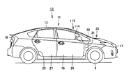
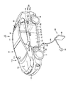
- FIG. 1 is a block diagram showing a vehicle 10.
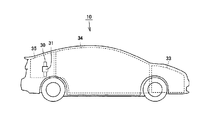
- FIG. 2 is a side view schematically showing a drive device accommodation chamber 33, a passenger compartment 34, and a luggage compartment 35 formed in the vehicle 10.
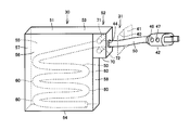
- FIG. 2 is a perspective view schematically showing a cord storage device 30 and a cord lead-out portion 31.
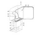
- FIG. 3 is a perspective view schematically showing a cord lead-out part 31.
- FIG. FIG. 1 is a block diagram showing a vehicle 10.
- FIG. 2 is a side view schematically showing a drive device accommodation chamber 33, a passenger compartment 34, and a luggage compartment 35 formed in the vehicle 10.
- FIG. 2 is a perspective view schematically showing a cord storage device 30 and a cord lead-out portion 31.
- FIG. 3 is a perspective view schematically showing a cord lead-out part 31.
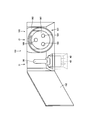
- FIG. 3 is a cross-sectional view of the cord storage device 30 and is a cross-sectional view of the cord storage device 30 as viewed from above the cord storage device 30. It is sectional drawing which shows the code
- FIG. It is a perspective view which shows typically the protruding part 65 and the structure of the circumference
- 6 is a schematic diagram showing a manufacturing process of the charging cable 50.
- FIG. 2 is a cross-sectional perspective view showing a charging cable 50.
- FIG. 20 is a rear perspective view showing the vehicle 10 shown in FIG. 19.
- FIG. 6 is a perspective view showing a first modification of the mounting position of the cord lead portion 31. It is a side view which shows the 2nd modification of the mounting position of the code
- FIG. It is a perspective view of the vehicle 10 shown in FIG. It is a side view showing the 3rd modification of cord drawer part 31 and cord accommodation device 30.
- FIG. 1 is a side view of a vehicle 10.
- FIG. 3 is a perspective view showing the charging unit 150 as seen from above. It is a side view of the vehicle 10 shown in FIG. In the vehicle 10 which concerns on this Embodiment 3, it is a side view which shows the 1st modification of the mounting position of the code
- FIG. It is a perspective view of the vehicle 10 which concerns on a 2nd modification.
- Fig. 31 is a side view of the vehicle 10 shown in Fig. 30.
- FIG. 10 is a perspective view showing a second modification of vehicle 10 according to the third embodiment. It is a perspective view of the vehicle 10 which concerns on a 3rd modification. It is a side view of the vehicle 10 shown in FIG.
- a cable housing device and a vehicle according to an embodiment of the present invention will be described with reference to FIGS.
- an example applied to a so-called hybrid vehicle will be described, but it goes without saying that the embodiment can also be applied to an electric vehicle.
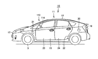
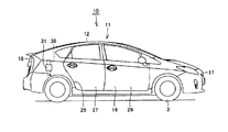
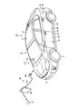
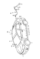
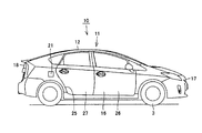
- FIG. 1 is a perspective view showing a vehicle 10 provided with a cord accommodating device 30 according to the present embodiment.
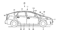
- 2 is a right side view of the vehicle 10 shown in FIG. 1
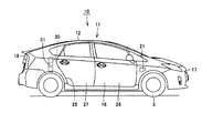
- FIG. 3 is a left side view of the vehicle 10 shown in FIG.
- a vehicle 10 includes a body 11 that forms an outline of the vehicle 10, a fuel tank FT and a battery B that are accommodated in the body 11.
- the surface of the body 11 includes an upper surface 12, a lower surface 13, and a peripheral surface 14, and the peripheral surface 14 includes a side surface 15 and a side surface 16, a front surface 17, and a back surface 18.
- the side surface 15 is formed with an opening 22 for getting on and off, and the body 11 includes a door 23 and a door 24 for opening and closing the opening 22 for getting on and off.
- the driver's seat 113 is disposed on the side surface 16 side with respect to the side surface 15, and an operation unit such as a handle 114 for operating the vehicle 10 is provided in the driver's seat 113. Is provided.
- the side surface 15 is provided with a fueling part 20 and a charging part 21, the fueling part 20 is arranged on the rear side from the opening part 22 for getting on and off, and the charging part 21 is arranged on the front side from the opening part 22 for getting on and off. ing.
- the oil supply part 20 includes a nozzle insertion part 20a into which a nozzle part of an oil supply nozzle provided outside is inserted, and a lid part 20b provided in the body 11. By opening the cover part 20b, the opening part of the nozzle insertion part 20a is exposed to the outside, and the nozzle of the fueling nozzle can be inserted into the nozzle insertion part 20a.
- the nozzle insertion part is connected to the fuel tank FT, and the fuel supplied from the nozzle insertion part 20a is supplied to the fuel tank FT.
- the supplied fuel include gasoline and LP gas (Liquefied petroleum gas).
- liquid hydrogen, ethanol, etc. are mentioned in the vehicle provided with the fuel cell.
- the charging unit 21 includes a charging connector 21a to which a charging plug 93 provided outside is mounted, and a lid 21b provided on the body 11. By opening the lid portion 21b, the charging connector 21a is exposed to the outside, and the charging plug 93 can be attached to the charging connector 21a.
- the charging connector 21a of the charging unit 21 is supplied with high-voltage power of about 288V from the charging plug 93, for example.
- the charging connector 21a is connected to the battery B via a converter or the like, and the battery B is charged by the electric power supplied to the charging unit 21.
- the side surface 16 is formed with an opening 25 for getting on and off
- the body 11 is provided with a door 26 and a door 27 for opening and closing the opening 25 for getting on and off.
- the cord lead-out portion 31 is arranged on the rear side of the side surface 16 with respect to the opening portion 25 for getting on and off.
- the cord drawing portion 31 includes a charging plug and a lid portion provided on the body 11. The charging plug can be pulled out by opening the lid. The details of the structure of the cord drawing portion 31 and the cord housing device 30 will be described later.
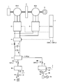
- FIG. 4 is a block diagram showing the vehicle 10.
- the vehicle 10 includes an engine 1, motor generators MG1, MG2, a power split mechanism 2, a battery B, a capacitor C, a reactor L, a converter 4, an inverter 5, an inverter 6, and a vehicle ECU (Electronic Control Unit). ) 7, switching elements 8 ⁇ / b> A and 8 ⁇ / b> B such as a relay, a converter 9, a cord drawing unit 31, and a charging unit 21.
- the power split mechanism 2 is coupled to the engine 1 and the motor generators MG1 and MG2, and distributes power between them.
- a planetary gear mechanism having three rotating shafts of a sun gear, a planetary carrier, and a ring gear is used. These three rotation shafts are connected to the rotation shafts of engine 1 and motor generators MG1, MG2.
- the rotor of motor generator MG1 is hollow, and the engine 1 and motor generators MG1 and MG2 are mechanically connected to power split mechanism 2 by passing the crankshaft of engine 1 through the center thereof.
- rotation shaft of the motor generator MG2 is coupled to the front wheels 3 as drive wheels by a reduction gear and a differential gear (not shown).
- a power reducer for the rotation shaft of motor generator MG2 may be further incorporated in power split device 2.
- the motor generator MG1 is incorporated in the vehicle 10 so as to operate as a generator driven by the engine 1 and to operate as an electric motor capable of starting the engine 1.
- Motor generator MG2 is incorporated in vehicle 10 as an electric motor that drives front wheels 3 that are drive wheels of vehicle 10.
- Motor generators MG1, MG2 are, for example, three-phase AC synchronous motors.
- Motor generators MG1 and MG2 include a three-phase coil including a U-phase coil, a V-phase coil, and a W-phase coil as a stator coil.
- Motor generator MG1 generates a three-phase AC voltage using the engine output, and outputs the generated three-phase AC voltage to inverter 5.
- Motor generator MG ⁇ b> 1 generates driving force by the three-phase AC voltage received from inverter 5, and starts engine 1.
- Motor generator MG2 generates vehicle driving torque by the three-phase AC voltage received from inverter 6. Motor generator MG2 generates a three-phase AC voltage and outputs it to inverter 6 during regenerative braking of the vehicle.
- the switching element 8A is provided between the converter 9 and the cord accommodating device 30, and the switching element 8B is disposed between the charging unit 21 and the converter 9.
- the switching element 8A connects the cord housing device 30 and the converter 9 or disconnects the cord housing device 30 and the converter 9 from each other.
- Switching element 8 ⁇ / b> B connects charging unit 21 and converter 9, or disconnects charging unit 21 and converter 9.
- the switching element 8A is switched ON / OFF by a control signal CNTL1 of the vehicle ECU 7.
- the drive of the converter 9 is controlled by a control signal CNTL2 from the vehicle ECU 7.
- the switching element 8B is switched ON / OFF by a control signal CNTL3 from the vehicle ECU 7.
- the vehicle ECU 7 When charging the battery B using the charging plug of the cord lead-out unit 31, the vehicle ECU 7 turns on the switching element 8A and connects the battery B and the converter 9. And vehicle ECU7 drives the converter 9 so that alternating current power supplied from the power supply may be converted into direct current power. At this time, the vehicle ECU 7 turns off the switching element 8B.
- the vehicle ECU 7 When the charging plug 93 is connected to the charging connector 21a of the charging unit 21 to charge the battery B, the vehicle ECU 7 turns on the switching element 8B to connect the charging unit 21 and the converter 9. At this time, the vehicle ECU 7 turns off the switching element 8A. Then, the vehicle ECU 7 drives the converter 9 so as to convert AC power supplied from the external power supply 91 into DC power.
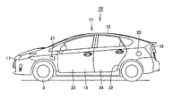
- FIG. 5 is a side view schematically showing the drive device accommodation chamber 33, the passenger compartment 34, and the luggage compartment 35 formed in the vehicle 10.
- a drive device accommodation chamber 33 in which the engine 1, motor generators MG1, MG2, etc. are accommodated, an occupant chamber 34 in which an occupant rides, and a luggage chamber 35 in which luggage and the like are placed are formed.
- the drive device accommodation chamber 33 is disposed on the front side of the passenger compartment 34, and the luggage compartment 35 is disposed on the rear side of the passenger compartment 34.
- the cord storage device 30 is provided in the luggage compartment 35.
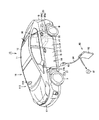
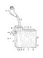
- FIG. 6 is a perspective view schematically showing the cord storage device 30 and the cord lead-out portion 31, and
- FIG. 7 is a perspective view schematically showing the cord lead-out portion 31. As shown in FIG.
- the cord lead-out portion 31 includes a storage chamber 40 having an opening formed in the side surface 16, and a lid portion 41 provided on the side surface 16 that opens and closes the opening of the storage chamber 40. And a plug housing hole 43 formed in the housing chamber 40, a charging plug 42, and a charging cable 50 connected to the charging plug 42.
- the charging plug 42 is provided so as to be accommodated in the plug accommodation hole 43, and a charging cable 50 is connected to the charging plug 42.
- a switch 46 and a switch 47 are provided on the casing of the charging plug 42.
- a hole 44 through which the charging cable 50 is taken in and out is formed on the inner wall surface of the storage chamber 40.
- a packing 45 is provided at the opening edge of the hole 44.
- the packing 45 suppresses foreign matter or water adhering to the charging cable 50 from entering the body 11.
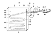
- the cord storage device 30 includes a charging cable 50, a charging plug 42 provided at the end of the charging cable 50 on the drawer side, a casing 51 that stores the charging cable 50, a cord feeding device 52, Is provided.
- the charging cable 50 is accommodated in a state of being bent so as to meander.
- the housing 51 includes a top plate 53, a bottom plate 54, side plates 55 and 56, a back plate 57, and a front plate 58.
- the top plate 53 and the bottom plate 54 are arranged in the vehicle height direction, and the front plate 58 and the back plate 57 are arranged in the width direction of the vehicle 10.
- the side plate 55 and the side plate 56 are arranged in the front-rear direction of the vehicle 10.
- a code feeding device 52 is provided on the front plate 58.
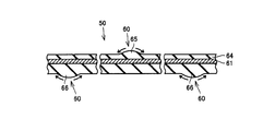
- FIG. 8 is a cross-sectional view of the cord storage device 30, and is a cross-sectional view of the cord storage device 30 as viewed from above the cord storage device 30. 8 and 7, the charging cable 50 is bent so as to be folded back at the bending portion 60, and the portions of the charging cable 50 located between the bending portions 60 overlap each other in the height direction. Contained.
- the charging cable 50 is located between the bent portions 60 in the charging cable 50.
- the parts are accommodated so as to overlap each other in the height direction.
- the distance L between the side plate 55 and the side plate 56 is a little larger than the width W of the charging cable 50, and the cord accommodating device 30 is made thin. As described above, by reducing the thickness of the cord housing device 30, it is possible to improve the mounting efficiency of equipment in the vehicle 10.
- the interval L is set to a range that is 1.2 times or more and less than 2.0 times the width W.
- the side plate 55 and the side plate 56 support the side surface of the charging cable 50 bent in a meandering manner, and the posture of the charging cable 50 is maintained.
- the side plate 55 and the side plate 56 are employed as the support members that support the side surfaces of the charging cable 50 in the cord housing device 30, but the side plates 55 and the side plates are used as the support members.
- Members other than 56 may be provided in the cord storage device 30.
- a protruding plate that supports the side surface of the charging cable 50 may be provided on the back plate 57 or the front plate 58.
- the code feeding device 52 includes a housing 70 provided on the front plate 58 and devices accommodated in the housing 70. As shown in FIG. 8, a part of the peripheral surface of the housing 70 defines a part of the storage chamber 40, and the housing 70 has a hole 44 into which the charging cable 50 is inserted. Yes.
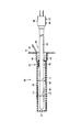
- FIG. 9 is a cross-sectional view showing the code feeding device 52.
- the code feeding device 52 includes a housing 70, rollers 71 and 72 provided in the housing 70, a rotating electrical machine 73 that rotationally drives the roller 71, and rotational driving of the roller 71. 72, and a power transmission mechanism 74 that transmits the power to 72.
- the roller 71 and the roller 72 are arranged with a space therebetween, and the charging cable 50 is sandwiched between the roller 71 and the roller 72.
- the rotating electrical machine 73 includes a case, a rotor 75 accommodated in the case, and a stator 76, and the stator 76 flows through the annular stator core 78, the stator coil 77 attached to the stator core 78, and the stator coil 77.
- the rotor 75 is fixed to the rotation shaft of the roller 71, and the rotor 75 includes a rotor core and a magnet provided in the rotor core.
- the power transmission mechanism 74 includes a gear 80 fixed to the rotation shaft of the roller 71 and a gear 81 fixed to the rotation shaft of the roller 72, and the gear 80 and the gear 81 mesh with each other.
- the charging cable 50 is sent out from the cord housing device 30 or the charging cable 50 is pulled into the cord housing device 30.
- the cross-sectional shape perpendicular to the length direction of the charging cable 50 is formed to be a circular shape.
- the charging cable 50 includes core wires 61, 62, 63 and an insulating insulating film 64 that covers the core wires 61, 62, 63.
- the insulating film 64 is made of an insulating resin material, and is made of an elastically deformable material.
- the core wire 61 and the core wire 62 are power lines, and the core wire 63 is, for example, a ground line.
- FIG. 10 is a cross-sectional view schematically showing a state in which a tensile force is applied to both ends of the charging cable 50.
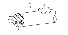
- FIG. 11 is a perspective view schematically showing the configuration of the raised portion 65 and its surroundings.
- the raised portion 65 has an internal stress in the direction of bending the charging cable 50. .
- FIG. 12 when the tensile force applied to the charging cable 50 is removed, the charging cable 50 is bent back at the portion of the raised portion 65. Thereby, the bending part 60 is formed in the charging cable 50.
- the raised portion 65 When the charging cable 50 is bent, the raised portion 65 is extended, and the height of the raised portion 65 is lowered. As a result, in the state bent by the bending part 60, the swelling of the raised part 65 becomes difficult to visually recognize.
- the bulging portion 65 and the bulging portion 66 are viewed from a position distant from the bulging portion 65 and the bulging portion 66 in the extending direction of the charging cable 50, the bulging portion 65 and the bulging portion 66 are connected to the charging cable 50. It is provided at a position that is symmetric with respect to the center line. When the tensile force applied to the charging cable 50 is removed, the charging cable 50 is bent by the internal stress of the raised portion 66.
- the raised portions 65 and the raised portions 66 are alternately provided in the length direction of the charging cable 50. For this reason, in the natural state, the charging cable 50 bends at each of the raised portions 65 and the raised portions 66, and the charging cable 50 has a meandering shape.
- the natural state means a state where no external force is applied from the outside.
- the charging cable 50 is bent in a meandering manner, and portions located between the bent portions 60 overlap each other in the height direction.
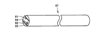
- a method for manufacturing the charging cable 50 will be described with reference to FIGS. 13 and 14. First, a cable 67 having core wires 61, 62, and 63 and an insulating coating 64 that covers the core wires 61 to 63 is formed.
- the cable 67 is not formed with a raised portion 65, and is in a substantially straight line state when no external force is applied.
- the cable 67 is put in the heating furnace 82, and it heats.
- the heating furnace 82 heats the housing 83, a plurality of support shafts 84 and support shafts 85 provided in the housing 83, a fixing portion 86 and a fixing portion 87 that fix an end portion of the cable 67, and the cable 67. And a heater 88.
- the support shafts 84 and the support shafts 85 are provided alternately in the height direction, and the support shafts 84 and the support shafts 85 are arranged at intervals in the horizontal direction.
- the cable 67 is hooked on the support shaft 84 and the support shaft 85, one end of the cable 67 is fixed to the fixing portion 86, and the other end of the cable 67 is fixed to the fixing portion 87. .
- the cable 67 is bent by the support shafts 84 and 85, and the cable 67 is formed in a meandering shape.
- the cable 67 is heated for a predetermined time, the cable 67 is cooled, so that the charging cable 50 brazed in a serpentine shape can be obtained.
- the bulging portion 65 and the bulging portion 66 are formed on the outer periphery of the portion supported by the support shaft 84 and the support shaft 85, and the bending portion 60 is formed on the charging cable 50.
- the bent charging cable 50 is accommodated in the cord accommodating device 30 so as to be folded at the bending portion 60.
- the entire cable 67 is heated using the heater 88.
- a heater is provided in the support shafts 84 and 85, and the cable 67 is locally connected to the support shafts 84 and 85. You may make it heat to.
- the user opens the lid 41 shown in FIG. 7 and takes out the charging plug 42 from the plug housing hole 43.
- the switch 46 for drawing out the charging cable.
- the vehicle ECU 7 drives the rotating electrical machine 73 so that the charging cable 50 is pulled out from the cord housing device 30.
- the charging cable 50 is sequentially sent out from the housing chamber 40 to connect the charging plug 42 to the external power source.
- the switch 47 When the switch 47 is turned on, the vehicle ECU 7 drives the rotating electrical machine 73 so that the charging cable 50 is drawn into the cord housing device 30.
- the charging cable 50 drawn to the outside is brazed so as to bend at the bent portion 60 as described above, it is bent at the bent portion 60 in the cord accommodating device 30 and sequentially accommodated in the cord accommodating device 30. Is done.
- the cord feeding device 52 can pull out the charging cable 50 from the cord housing device 30 or pull the drawn charging cable 50 into the cord housing device 30.
- the cord storage device 30 assists the user in assisting the user in pulling out the charging cable 50 from the cord lead-out portion 31, and the user injecting the charging cable 50 into the cord lead-out portion 31. It has an assist function. Therefore, a configuration for achieving the function will be described with reference to FIGS.
- the voltage sensor 79 detects the voltage of the current flowing through the stator coil 77, and the vehicle ECU 7 detects the back electromotive force generated in the stator coil 77 based on the voltage information sent from the voltage sensor 79. Detect voltage value.
- the roller 71 and the roller 72 that sandwich the charging cable 50 rotate.
- the roller 71 rotates
- the rotor 75 rotates
- the rotor 75 fixed to the shaft portion of the rotor 75 rotates in one direction.
- the magnet provided in the rotor 75 also rotates, and a back electromotive force is generated in the stator coil 77.
- the roller 71 and the roller 72 that sandwich the charging cable 50 rotate.
- the roller 71 rotates, the rotor 75 rotates in the direction opposite to the one direction.
- a counter electromotive force is generated in the stator coil 77.
- the vehicle ECU 7 determines whether the charging cable 50 is pulled out from the cord housing device 30 or whether the charging cable 50 is pushed into the cord housing device 30 based on the positive and negative back electromotive forces generated in the stator coil 77. .
- Vehicle ECU 7 calculates the drawing speed of charging cable 50 or the pushing speed of charging cable 50 from the absolute value of the back electromotive force generated in stator coil 77.
- the vehicle ECU 7 drives the rotating electrical machine 73 so that the charging cable 50 is pulled out from the cord housing device 30 at a speed equal to or higher than the calculated pulling speed. Then, after the cord feeding device 52 pulls out the charging cable 50 by a predetermined length, the vehicle ECU 7 stops driving the rotating electrical machine 73.
- the vehicle ECU 7 determines that the charging cable 50 is pushed in, the vehicle ECU 7 drives the rotating electrical machine 73 so that the charging cable 50 is drawn into the cord housing device 30 at a speed equal to or higher than the calculated pushing speed.
- the vehicle ECU 7 stops driving the rotating electrical machine 73.
- the cord housing device 30 has a function of extending the charging cable 50 to the outside when the user pulls the charging cable 50 without pressing the switch 46, and the charging cable 50 without the user pressing the switch 47.
- a function for pulling the charging cable 50 into the cord housing device 30 when the cord housing device 30 is pushed is also provided.
- the vehicle 10 according to the present embodiment has a function for preventing the charging by the charging plug 42 and the charging by the charging plug 93 from being performed simultaneously. A configuration for achieving the function will be described with reference to FIGS. 4 and 7.
- a contact sensor 95 is provided in the plug housing hole 43.
- the contact sensor 95 comes into contact with the charging plug 42 housed in the plug housing hole 43 and is turned on when it is in contact with the charging plug 42, and is turned off when the charging plug 42 is separated from the contact sensor 95.
- the contact sensor 95 sends a signal to the vehicle ECU 7.
- the charging unit 21 includes a charging connector 21 a to which a charging plug 93 is connected and a contact sensor 97.
- the contact sensor 97 is turned on when it comes into contact with the charging plug 93 when the charging plug 93 is connected to the charging connector 21 a, and is turned off when the contact sensor 97 is not in contact with the charging plug 93.
- the contact sensor 97 sends a signal to the vehicle ECU 7.
- the vehicle ECU 7 turns off the switching element 8B when the contact sensor 95 is turned off. Thereby, when the charging plug 42 is pulled out, the charging connector 21a and the converter 9 are disconnected.
- the contact sensor 97 when the contact sensor 97 is turned on, the switching element 8A is turned off. Thereby, when the charging plug 93 is connected to the charging connector 21a, the cord lead-out portion 31 is disconnected from the converter 9. Thereby, it can suppress that electric power is supplied from both the charging plug 93 of the external charging equipment 90 and the charging plug 42 of the cord drawing part 31.
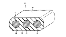
- FIG. 15 is a cross-sectional perspective view showing the charging cable 50.
- 16 is a perspective view schematically showing a cord housing device 30 on which the charging cable 50 shown in FIG. 15 is mounted
- FIG. 17 is a perspective view schematically showing the housing chamber 40 shown in FIG.
- the charging cable 50 shown in FIG. 15 includes core wires 61, 62, 63 and an insulating film 64 that covers the core wires 61, 62, 63.
- the core wire 62, the core wire 61, and the core wire 63 are provided so that it may arrange in a line.
- the thickness of the charging cable 50 is smaller than the width of the charging cable 50 in the arrangement direction of the core wire 62, the core wire 61, and the core wire 63.
- Charging cable 50 is formed in a flat plate shape, and charging cable 50 includes a main surface 98 and a main surface 99 arranged in the thickness direction.
- the charging cable 50 accommodated in the cord accommodation device 30 is accommodated by being bent in a meandering manner.
- Roller 71 is in contact with main surface 98 shown in FIG. 15, and roller 72 is in contact with main surface 99.
- the charging cable 50 can be prevented from being twisted.
- FIG. 18 is a perspective view showing the external charging facility 90 shown in FIG. 1 and the like. As shown in FIG. 18, the external charging facility 90 is also formed in the same manner as the cord housing device 30.
- the external charging facility 90 includes a charging plug 93, a cord 94 connected to the charging plug 93, a casing 101 that accommodates the cord 94, and a cord feeding device 102 provided in the casing 101.
- the charging plug 93 can be connected to a charging connector 21 a provided in the charging unit 21 of the vehicle 10.
- the cord 94 includes a plurality of bent portions 110 provided at intervals in the length direction of the cord 94, and the cord 94 is accommodated in the cord accommodating device 30 in a meandering state.
- the housing 101 is made compact.
- the housing 101 includes a top plate 103, a bottom plate 104, a side plate 105, a side plate 106, a back plate 107 and a front plate 108 formed between the top plate 103 and the bottom plate 104.
- a hole 115 is formed in the bottom plate 104. For this reason, even if dust or water adhering to the cord 94 accumulates in the bottom plate 104, it is discharged from the hole 115 to the outside.
- a hole is formed in the top plate 103, and a packing 112 is provided in this hole.
- the cord 94 is provided on the terminal end side of the cord 94 and includes a lead wire 111 pulled up from the bottom plate 104 toward the top plate 103, and the lead wire 111 is drawn out of the housing 101 through the packing 112. .
- the leader line 111 is connected to the external power source 91 via a converter or the like.
- the present invention can be applied not only to the cord storage device 30 mounted on the vehicle but also to the external charging facility 90.
- Embodiment 1 the example in which the driver's seat 113 is arranged on the side surface 16 side has been described, but the driver's seat 113 may be arranged on the side surface 15 side.
- the operation unit such as the handle 114 is also arranged on the side surface 15 side.
- the oil supply unit 20 and the charging unit 21 are provided on the same side surface 15, and the cord lead-out unit 31 is the side surface 15 of the peripheral surface 14. It is provided in other parts.
- the charging part 21 and the fueling part 20 are not arranged around the cord drawing part 31, and an operator who charges the battery B using the cord drawing part 31 is arranged with the cord drawing part 31, the charging part 21, and the charging part 21. It is possible to prevent the oil supply unit 20 from being confused.
- the vehicle 10 When charging using the cord drawing unit 31, for example, the vehicle 10 is parked in a parking space of a house, the charging cable 50 and the charging plug 42 are pulled out from the cord drawing unit 31, and the charging plug 42 is connected to a household power source. Often connected to.
- the vehicle 10 when a vehicle is parked, the vehicle 10 is parked so that the back surface 18 of the vehicle 10 is closest to the house, or the vehicle 10 is parked in a state where it is laid sideways with respect to the house. In any of these parking modes, the back surface 18 of the vehicle 10 is located close to the house.
- a general household power source to which the charging plug 42 is connected is provided in the house.
- the distance between the general household power supply and the cord lead-out portion 31 is The charging plug 42 can be easily connected to a household power source.
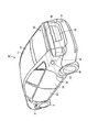
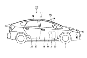
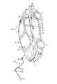
- FIG. 19 is a side view showing the vehicle 10 according to the second embodiment
- FIG. 20 is a rear perspective view showing the vehicle 10 shown in FIG.
- the charging unit 21 is disposed on the front side of the side surface 15 with respect to the opening 22 for getting on and off, and the refueling unit 20 is arranged on the rear side with respect to the opening 22 for getting on and off.
- the cord drawing portion 31 is provided on the back surface 18.
- the cord storage device 30 is disposed in the luggage compartment 35. The cord storage device 30 is made compact, and the volume of the luggage compartment 35 is prevented from being reduced.
- the bottom surface of the luggage compartment 35 is formed by a floor panel provided on the floor panel, and the battery B is disposed on the floor panel and below the floor panel. For this reason, the cord storage device 30 and the battery B can be brought close to each other by arranging the cord storage device 30 in the luggage compartment 35. As a result, the wiring length of the connection wiring that connects the cord housing device 30 and the battery B can be shortened.
- the refueling unit 20 and the charging unit 21 are provided on the side surface 15 of the circumferential surface of the vehicle 10, and the cord lead-out unit 31 is provided on a portion other than the side surface 15 of the circumferential surface of the vehicle 10.
- the oil supply unit 20 and the charging unit 21 are connected to an oil supply nozzle or a charging plug provided in an external facility. For this reason, the case where the refueling operation is performed using the refueling unit 20 and the case where the recharging operation is performed using the charging unit 21 both use external equipment.
- the cord lead-out unit 31 pulls out the charging plug 42 of the cord lead-out unit 31 from the vehicle 10 and connects the charging plug 42 to an external power source provided outside the vehicle 10. For this reason, when charging work is performed using the cord lead-out unit 31, external equipment is not essential, and for example, a household power source may be used.
- the cord lead-out part 31 is basically not used.
- the cord lead-out portion 31 is provided in a portion of the peripheral surface 14 other than the side surface 15 where the oil supply portion 20 and the charging portion 21 are provided. It is possible to suppress confusion between the cord lead-out unit 31, the oil supply unit 20, and the charging unit 21.
- FIG. 21 is a perspective view showing a first modified example of the mounting position of the cord lead-out portion 31, and in the example shown in FIG. 21, the cord lead-out portion 31 is provided on the front surface 17.
- the cord storage device 30 is formed compactly, it can be mounted in a dead space in the drive device storage chamber 33.
- the charging plug 42 is connected to a household power source.
- the cord lead-out portion 31 is provided on the front surface 17, it is easily visible from the outside. Furthermore, it is easy to visually recognize the charging cable 50 drawn out from the cord lead-out portion 31 also from the driver seat 113. For this reason, it can suppress that a user starts the vehicle 10 accidentally during charge.
- FIG. 22 is a side view showing a second modification of the mounting position of the cord lead-out portion 31.
- FIG. FIG. 23 is a perspective view of the vehicle 10 shown in FIG. In the example shown in FIG. 22, the driver's seat 113 is located on the side surface 16 side.
- the cord lead-out portion 31 is the side surface 16 and is disposed on the front side of the entrance / exit opening portion 25.
- the cord storage device 30 is mounted in the drive device storage chamber 33. Since the cord storage device 30 is thinned as described above, the cord storage device 30 can be mounted in a dead space in the drive device storage chamber 33.
- the oil supply part 20 and the charging part 21 are provided in the side surface 15, as shown in FIG.
- FIG. 24 is a side view showing a third modification of the cord lead-out portion 31 and the cord storage device 30. Also in the example shown in FIG. 24, the oil supply unit 20 and the charging unit 21 are provided on the side surface 15 as shown in FIG.
- the cord storage device 30 is mounted in the door 26.
- the door 26 is a door that is opened when the driver gets on the driver's seat 113. For this reason, when the charging cable 50 is pulled out from the cord lead-out part 31, the driver can confirm that the charging cable 50 is pulled out reliably.
- the cord storage device 30 according to the third embodiment can be placed in the dead space of the door 26 because the cord storage device 30 according to the first embodiment is reduced in thickness as in the first embodiment. Thereby, the improvement of the mounting efficiency of the apparatus when it sees with the whole vehicle can be aimed at.
- FIG. 25 is a perspective view of the vehicle 10 according to the third embodiment
- FIG. 26 is a side view of the vehicle 10.
- the oil supply unit 20 is provided on the side surface 15, and the oil supply unit 20 is disposed on the rear side of the opening 22 for getting on and off.
- the charging unit 150 is provided on the side surface 16. Note that the charging unit 150 is disposed on the rear side of the side surface 16 with respect to the opening portion 25 for getting on and off.
- FIG. 27 shows the charging unit 150 and is a perspective view of the charging unit 150 as viewed from above.
- the charging unit 150 is accommodated in the accommodating chamber 151 formed in the side surface 16, a lid portion 152 provided on the side surface 16 for opening and closing the opening of the accommodating chamber 151, and the accommodating chamber 151.
- the charging plug 42 and the charging connector 161 accommodated in the accommodation chamber 151 are included.
- Charging connector 161 is connected to charging plug 93 of external charging facility 90 shown in FIG.
- the charging unit 21 and the cord lead-out unit 31 are accommodated in one accommodation chamber 151 and are opened and closed by one lid 152.
- the charging unit 21 and the cord lead-out unit 31 are both provided on the side surface 16.
- the charging connector 161 is provided on the side surface 16 opposite to the side surface 15 provided with the oil supply portion 20, and the cord lead-out portion 31 is provided on a portion of the peripheral surface 14 other than the side surface 15 provided with the oil supply portion 20. It has been. For this reason, the charging part 21 and the cord drawing part 31 are not arranged around the refueling part 20, and an operator who performs the refueling operation confuses the refueling part 20 with the charging part 21 and the cord drawing part 31. This can be suppressed.
- the cord lead-out part 31 provided in the charging part 150 is arranged on the rear side of the opening 25 for getting on and off.
- the cord lead-out portion 31 and the charging portion 21 are provided on the same side surface 16, and the devices are provided on the same unit circumferential surface when charging.
- the side 16 is close to the power source and the external charging equipment 90 in both cases of charging using the cord lead-out unit 31 and charging using the charging connector 161 of the charging unit 21.
- the vehicle 10 may be stopped as described above, and the driver can be prevented from mistaking the parking posture of the vehicle 10.
- the worker who performs the charging work can locate the cord lead-out part 31 and the charging part 21. Easy to grasp.
- FIG. 28 and 29 show a first modified example of the mounting positions of the cord lead-out portion 31 and the cord storage device 30 in the vehicle 10 according to the third embodiment.
- FIG. 28 is a perspective view of the vehicle 10 according to the first modification
- FIG. 29 is a side view of the vehicle 10 shown in FIG.
- the fuel filler 20 is provided on the side surface 15, and the fuel filler 20 is located on the rear side of the side surface 15 with respect to the opening 22 for getting on and off. It is provided at the position.
- the charging unit 21 is disposed on the rear side of the side surface 16 with respect to the getting-on / off opening 25, and the cord lead-out unit 31 is on the front side of the side surface 16 with respect to the getting-on / off opening 25. Is arranged.
- the cord accommodating device 30 is accommodated in the drive device accommodating chamber 33, for example.
- the charging unit 21 and the cord lead-out unit 31 are provided on the same side surface (unit side surface) 16. For this reason, when charging, it becomes difficult for an error to occur in the parking posture of the vehicle 10, and the burden on the driver can be reduced.
- the charging unit 21 and the refueling unit 20 are both devices for connecting a charging plug or a refueling nozzle provided in an external facility.
- the cord lead-out unit 31 is a device for pulling out devices such as the charging cable 50 and the charging plug 42.
- the cord lead-out unit 31 is a device for pulling out the devices mounted on the vehicle 10 to the outside.
- the operation of attaching the device outside the vehicle 10 to the vehicle 10 is performed, while the cord drawing unit 31 is used.
- an operation of taking out a device mounted on the vehicle 10 to the outside of the vehicle 10 is performed.
- the charging and refueling work performed using the charging unit 21 and the refueling unit 20 and the charging work performed using the cord lead-out unit 31 have a large procedure.
- the charging unit 21 and the oil supply unit 20 accompanied by the operation of attaching the device outside the vehicle 10 are arranged on the rear side of the entrance / exit openings 22 and 25, and the cord lead-out unit accompanied by the operation of drawing out the device mounted on the vehicle 10
- the cord lead-out unit accompanied by the operation of drawing out the device mounted on the vehicle 10
- the cord drawing part 31 is located in the vicinity of the driver's seat 113, the driver can easily visually recognize the charging cable 50 when the charging cable 50 or the like is drawn from the cord housing device 30.
- FIG. 30, FIG. 31, and FIG. 32 show a second modification of the vehicle 10 according to the third embodiment.
- FIG. 30 is a perspective view of the vehicle 10 according to the second modification
- FIG. 31 is a side view of the vehicle 10 shown in FIG.
- FIG. 32 is a perspective view of the vehicle 10 shown in FIG. 30 as viewed from the rear side.
- the oil filler 20 is provided on the side surface 15, and is disposed on the rear side of the side surface 15 with respect to the opening 22 for getting on and off.
- the charging unit 21 is disposed on the rear side of the side surface 16 with respect to the opening 25 for getting on and off.
- the cord lead portion 31 is provided on the back surface 18.
- the charging unit 21 and the cord drawing unit 31 are not provided around the refueling unit 20, and when the refueling operation is performed, the operator performs the refueling unit 20 and the charging unit 21. Further, it is possible to suppress confusion with the cord lead-out portion 31.
- FIG. 33 and 34 show a third modification of the vehicle 10 according to the third embodiment.
- FIG. 33 is a perspective view of the vehicle 10 according to the third modification
- FIG. 34 is a side view of the vehicle 10 shown in FIG.
- the oil filler 20 is disposed on the rear side of the side surface 15 with respect to the opening 22 for getting on and off.
- the cord lead-out portion 31 is disposed on the rear side of the side surface 16 with respect to the getting-on / off opening 25, and the charging portion 21 is on the front side of the side surface 16 with respect to the getting-on / off opening 25. Is arranged. Thus, the charging part 21 does not need to be located behind the boarding / alighting opening 25.
- the present invention can be applied to a cord storage device and a vehicle.
Landscapes
- Engineering & Computer Science (AREA)
- Mechanical Engineering (AREA)
- Power Engineering (AREA)
- Transportation (AREA)
- Life Sciences & Earth Sciences (AREA)
- Sustainable Development (AREA)
- Sustainable Energy (AREA)
- Electric Propulsion And Braking For Vehicles (AREA)
- Insertion, Bundling And Securing Of Wires For Electric Apparatuses (AREA)
Abstract
Description
好ましくは、上記コードの長さ方向に対して垂直な断面において、コードの断面形状は、円形形状である。好ましくは、上記コードの長さ方向に垂直な断面において、コードの厚さは、コードの幅よりも薄い。
図1は、本実施の形態に係るコード収容装置30を備えた車両10を示す斜視図である。図2は、図1に示す車両10の右側面図であり、図3は、図1に示す車両10の左側面図である。
図19から図24を用いて、本実施の形態2に係る車両10について説明する。図19は、本実施の形態2に係る車両10を示す側面図であり、図20は、図19に示す車両10を示す背面側の斜視図である。
図25から図34を用いて、本実施の形態3に係る車両10について説明する。図25は、本実施の形態3に係る車両10の斜視図であり、図26は、車両10の側面図である。この図25に示すように給油部20は、側面15に設けられており、給油部20は、乗降用開口部22よりも後方側に配置されている。図26に示すように、充電部150が側面16に設けられている。なお、充電部150は、側面16のうち、乗降用開口部25よりも後方側に配置されている。
Claims (20)
- 筐体(51)と、
前記筐体(51)内に収容されると共に、前記筐体(51)から引き出し可能なコード(50)と、
前記コード(50)の引き出し側の端部に設けられ、外部電源に接続可能なプラグ(42)と、
を備え、
前記コード(50)は該コード(50)の長さ方向に間隔をあけて設けられた曲げ部(60)で曲げ返され、蛇行状に延びるように形成され、
前記筐体(51)内において、前記コード(50)は、前記曲げ部(60)の間に位置する部分が互いに重なり合うように収容された、コード収容装置。 - 前記コード(50)は、芯線(61,62,63)と、前記芯線(61,62,63)を被覆する絶縁性被膜(64)とを含み、
前記コード(50)を伸ばした状態において、前記絶縁性被膜(64)のうち、前記曲げ部(60)の曲げ外周側に位置する部分に隆起部(65,66)が形成され、
前記隆起部(65,66)は、前記コード(50)を曲げ返すように前記コード(50)を付勢する、請求項1に記載のコード収容装置。 - 前記筐体(51)は、収容された前記コード(50)の一方の側面を支持する第1支持部と、他方の側面を支持する第2支持部とを含む、請求項1に記載のコード収容装置。
- 前記第1支持部および前記第2支持部は、前記筐体(51)の側壁部(55,56)である、請求項3に記載のコード収容装置。
- 前記第1支持部と前記第2支持部と間隔(L)は、前記コード(50)の幅(W1)の2倍以下とされた、請求項3に記載のコード収容装置。
- 前記コード(50)の長さ方向に対して垂直な断面において、前記コード(50)の断面形状は、円形形状である、請求項1に記載のコード収容装置。
- 前記コード(50)の長さ方向に垂直な断面において、前記コード(50)の厚さは、前記コード(50)の幅よりも薄い、請求項1に記載のコード収容装置。
- 前記コード(50)を前記筐体(51)から送入出させる送入出装置をさらに備え、
前記プラグは、第1スイッチおよび第2スイッチを含み、
前記送入出装置は、前記第1スイッチが押されると、前記コード(50)を前記筐体(51)から送り出すように駆動し、前記第2スイッチが押されると、前記コード(50)を前記筐体(51)内に送り込むように駆動する、請求項1に記載のコード収容装置。 - 前記コード(50)を前記筐体(51)から送入出させる送入出装置をさらに備え、
前記送入出装置は、前記コード(50)を前記筐体(51)内に送り込む方向の第1外力が前記コード(50)に加えられると、前記コード(50)を前記筐体(51)内に送り込むように駆動し、前記コード(50)を前記筐体(51)から送り出す方向の第2外力が前記コード(50)に加えられると、前記コード(50)を前記筐体(51)の外部に送り出すように駆動する、請求項1に記載のコード収容装置。 - 前記送入出装置は、前記コード(50)を送入出するローラ(71)と、前記ローラ(71)を駆動させるモータと、検出器とを含み、
前記モータは、前記ローラ(71)に接続されたロータ(75)と、前記ロータ(75)の周囲に配置されたステータ(76)と、前記ステータ(76)に設けられたコイル(77)とを含み、
前記検出器は、前記第1外力によって前記ロータ(75)が回転して、前記コイル(77)に生じる第1逆起電力と、前記第2外力によって前記ロータ(75)が回転して、前記コイル(77)に生じる第2逆起電力とを検知し、
前記モータは、前記第1逆起電力が生じたときに前記コード(50)を前記筐体(51)内に送り込むように駆動し、前記第2逆起電力が生じたときに前記コード(50)を前記筐体(51)の外部に送り出すように駆動する、請求項9に記載のコード収容装置。 - 前記筐体の底部に穴部が形成された、請求項1に記載のコード収容装置。
- 乗降用開口部が形成されたボディと、
前記ボディ内に収容されたバッテリと、
前記外部電源からの電力を前記バッテリに供給可能な、請求項1から請求項11のいずれかに記載のコード収容装置と、
前記ボディに設けられ、前記プラグ(42)および前記コード(50)を引き出し可能な引出部と、
を備え、
前記引出部は、前記乗降用開口部より後方側または前方側に配置された、車両。 - 乗降用開口部が形成されたボディ(11)と、
前記ボディ(11)内に収容されたバッテリ(B)と、
前記外部電源からの電力を前記バッテリ(B)に供給可能な、請求項1から請求項11のいずれかに記載のコード収容装置(30)と、
前記プラグ(42)および前記コード(50)を引き出し可能な引出部(31)と、
外部電源に接続された第1外部プラグ(93)が接続される第1コネクタ(21)と、
外部に設けられた第2外部プラグが接続され、前記第2外部プラグから電力と異なるエネルギが供給される第2コネクタ(20)と、
を備えた車両であって、
前記ボディ(11)は、車両の幅方向に配列する第1側面および第2側面を含み、
前記第1コネクタ(21)および前記第2コネクタ(20)は前記第1側面に設けられ、前記引出部(31)は、前記車両の周面のうち、前記第1側面以外の部分に設けられた、車両。 - 前記引出部(31)は、乗降開口部より後方側または前方側に配置された、請求項13に記載の車両。
- 前記引出部(31)は、前記第2側面に設けられた、請求項13に記載の車両。
- 乗降用開口部が形成されたボディ(11)と、
前記ボディ(11)内に収容されたバッテリ(B)と、
前記外部電源からの電力を前記バッテリ(B)に供給可能な、請求項1から請求項11のいずれかに記載のコード収容装置(30)と、
前記プラグ(42)および前記コード(50)を引き出し可能な引出部(31)と、
外部電源に接続された第1外部プラグ(93)が接続される第1コネクタ(21)と、
外部に設けられた第2外部プラグが接続され、前記外部第2プラグから電力と異なるエネルギが供給される第2コネクタ(20)と、
を備えた車両であって、
前記ボディ(11)は、車両の幅方向に配列する第1側面および第2側面を含み、
前記第1コネクタ(21)は前記第1側面に設けられ、
前記第2コネクタ(20)は前記第2側面に設けられ、
前記引出部(31)は、前記車両の周面のうち、前記第2側面以外の部分に設けられた、車両。 - 前記第1コネクタ(21)および前記引出部(31)は、前記乗降用開口部より後方側または前方側に設けられた、請求項16に記載の車両。
- 前記ボディ(11)の内部には、車両を操作する操作部が設けられ、
前記操作部は、前記第2側面よりも前記第1側面に近い位置に設けられた、請求項16に記載の車両。 - 乗降用開口部が形成されたボディ(11)と、
前記ボディ(11)内に収容されたバッテリ(B)と、
前記外部電源からの電力を前記バッテリ(B)に供給可能な、請求項1から請求項11のいずれかに記載のコード収容装置(30)と、
前記プラグ(42)および前記コード(50)を引き出し可能な引出部(31)と、
外部電源に接続された第1外部プラグ(93)が接続される第1コネクタ(21)と、
を備えた車両であって、
前記ボディ(11)は、上面と、下面と、前記上面および前記下面との間に設けられた複数の単位周面とを含み、
前記引出部(31)と前記第1コネクタ(21)とは、同一の単位周面に設けられた、車両。 - 前記ボディ(11)は、前記引出部(31)および前記第1コネクタ(21)が設けられた単位周面に設けられた蓋部を含み、
前記引出部(31)および前記第1コネクタ(21)は、前記蓋部によって開閉可能とされた、請求項19に記載の車両。
Priority Applications (5)
| Application Number | Priority Date | Filing Date | Title |
|---|---|---|---|
| JP2013505745A JP5673798B2 (ja) | 2011-03-24 | 2011-03-24 | コード収容装置および車両 |
| EP11861503.8A EP2690735A4 (en) | 2011-03-24 | 2011-03-24 | CABLE RECEIVING DEVICE AND VEHICLE |
| US13/985,188 US20140008135A1 (en) | 2011-03-24 | 2011-03-24 | Cord housing device and vehicle |
| CN201180069558XA CN103460539A (zh) | 2011-03-24 | 2011-03-24 | 软线收纳装置及车辆 |
| PCT/JP2011/057153 WO2012127678A1 (ja) | 2011-03-24 | 2011-03-24 | コード収容装置および車両 |
Applications Claiming Priority (1)
| Application Number | Priority Date | Filing Date | Title |
|---|---|---|---|
| PCT/JP2011/057153 WO2012127678A1 (ja) | 2011-03-24 | 2011-03-24 | コード収容装置および車両 |
Publications (1)
| Publication Number | Publication Date |
|---|---|
| WO2012127678A1 true WO2012127678A1 (ja) | 2012-09-27 |
Family
ID=46878871
Family Applications (1)
| Application Number | Title | Priority Date | Filing Date |
|---|---|---|---|
| PCT/JP2011/057153 Ceased WO2012127678A1 (ja) | 2011-03-24 | 2011-03-24 | コード収容装置および車両 |
Country Status (5)
| Country | Link |
|---|---|
| US (1) | US20140008135A1 (ja) |
| EP (1) | EP2690735A4 (ja) |
| JP (1) | JP5673798B2 (ja) |
| CN (1) | CN103460539A (ja) |
| WO (1) | WO2012127678A1 (ja) |
Cited By (7)
| Publication number | Priority date | Publication date | Assignee | Title |
|---|---|---|---|---|
| CN103346447A (zh) * | 2013-07-16 | 2013-10-09 | 吴江华鹏制罐厂 | 一种可伸缩式插头 |
| JP2014180121A (ja) * | 2013-03-14 | 2014-09-25 | Nitto Kogyo Co Ltd | 充電ケーブルの自動巻取装置 |
| JP2014177324A (ja) * | 2013-03-14 | 2014-09-25 | Nitto Kogyo Co Ltd | 充電ケーブルの自動巻取装置 |
| JP2018034756A (ja) * | 2016-09-02 | 2018-03-08 | トヨタ自動車株式会社 | 車両後部構造 |
| JP2018129956A (ja) * | 2017-02-09 | 2018-08-16 | いすゞ自動車株式会社 | 車両用充電装置 |
| JP2020104607A (ja) * | 2018-12-26 | 2020-07-09 | トヨタ自動車株式会社 | 電気自動車 |
| CN113183737A (zh) * | 2020-01-10 | 2021-07-30 | 奥动新能源汽车科技有限公司 | 传感器、快换支架组件及电动汽车 |
Families Citing this family (24)
| Publication number | Priority date | Publication date | Assignee | Title |
|---|---|---|---|---|
| CN104309949A (zh) * | 2014-10-27 | 2015-01-28 | 常州市武进长江滚针轴承有限公司 | 数据线收纳装置 |
| JP2017178083A (ja) * | 2016-03-30 | 2017-10-05 | トヨタ自動車株式会社 | ハイブリッド自動車 |
| CN106560580A (zh) * | 2016-04-15 | 2017-04-12 | 中兴新能源汽车有限责任公司 | 一种载车板及立体车库 |
| FR3050192B1 (fr) * | 2016-04-18 | 2019-05-03 | Renault S.A.S | Dispositif portatif de devidage d’un cable electrique, notamment un cable de charge pour un vehicule electrique ou hybride |
| WO2018154840A1 (ja) * | 2017-02-23 | 2018-08-30 | 三菱電機株式会社 | 電気製品の筐体 |
| CN106926726B (zh) * | 2017-03-22 | 2018-07-10 | 张海烽 | 一种新能源汽车用的供电装置 |
| CN106864299A (zh) * | 2017-04-10 | 2017-06-20 | 北京智充科技有限公司 | 一种电动汽车充电枪的挂线收纳装置 |
| CN108248440A (zh) * | 2018-02-08 | 2018-07-06 | 东莞市趣电智能科技有限公司 | 一种自助式充电桩 |
| CN108944552A (zh) * | 2018-02-08 | 2018-12-07 | 东莞市趣电智能科技有限公司 | 一种自助式充电桩 |
| USD902866S1 (en) * | 2018-08-01 | 2020-11-24 | Phoenix Contact E-Mobility Gmbh | Cable feed-through for electric vehicles |
| US11414013B2 (en) * | 2018-11-07 | 2022-08-16 | Volvo Truck Corporation | Viewing system for a vehicle and vehicle comprising such viewing system |
| CN109799185B (zh) * | 2019-02-26 | 2024-07-19 | 国网山西省电力公司晋城供电公司 | 一种多组电缆电压等级连续识别的设备及其使用方法 |
| NL2023045B1 (en) * | 2019-05-01 | 2020-12-02 | Prysmian Spa | Cable assembly |
| DE102020212947A1 (de) | 2020-10-14 | 2022-04-14 | Ford Global Technologies, Llc | Einrichtung zur Aufnahme eines Ladekabels für Elektro- und Hybridfahrzeuge |
| CN113213278B (zh) * | 2021-04-22 | 2022-05-24 | 中国电子科技集团公司第二十九研究所 | 一种应用于往复式转台的扁平式电缆卷绕机构 |
| FR3123850A1 (fr) * | 2021-06-10 | 2022-12-16 | Psa Automobiles Sa | Dispositif de stockage d’une rallonge electrique comprenant une protection de carrosserie |
| DE102021129713B4 (de) | 2021-11-15 | 2025-02-20 | Meindl-Köhle Umform- und Systemtechnik GmbH & Co. KG | Kabelspeicher- und -ausgabevorrichtung |
| IT202200010376A1 (it) * | 2022-05-19 | 2023-11-19 | Fca Italy Spa | "Gruppo di ricarica di un autoveicolo a trazione elettrica" |
| IT202200010385A1 (it) * | 2022-05-19 | 2023-11-19 | Fca Italy Spa | "Gruppo di ricarica di un autoveicolo a trazione elettrica! |
| IT202200010367A1 (it) * | 2022-05-19 | 2023-11-19 | Fca Italy Spa | "Gruppo di ricarica di un autoveicolo a trazione elettrica" |
| FR3138075A1 (fr) * | 2022-07-21 | 2024-01-26 | Psa Automobiles Sa | Vehicule automobile comportant un dispositif d’enroulement d’un cable electrique |
| US20250262961A1 (en) * | 2023-08-22 | 2025-08-21 | Lg Electronics Inc. | Charger |
| US20250136405A1 (en) * | 2023-11-01 | 2025-05-01 | Lockheed Martin Corporation | Cable management drive system for industrial robots |
| FR3159934A1 (fr) * | 2024-03-08 | 2025-09-12 | Stellantis Auto Sas | Vehicule automobile comprenant un cordon de recharge d’une batterie |
Citations (14)
| Publication number | Priority date | Publication date | Assignee | Title |
|---|---|---|---|---|
| JPS5288684U (ja) * | 1975-12-26 | 1977-07-02 | ||
| JPS5936528U (ja) * | 1982-08-31 | 1984-03-07 | 三和電線工業株式会社 | 折畳式平形ケ−ブル |
| JPH07117492A (ja) | 1993-10-19 | 1995-05-09 | Honda Motor Co Ltd | 電動車両の充電コード収納構造 |
| JPH1016670A (ja) * | 1996-07-02 | 1998-01-20 | Sumitomo Wiring Syst Ltd | 自動車のドアヒンジ部におけるワイヤハーネス配索構造 |
| JPH118941A (ja) | 1997-06-16 | 1999-01-12 | Mitsubishi Heavy Ind Ltd | 充電器付き電池ユニット |
| JP2004032869A (ja) * | 2002-06-25 | 2004-01-29 | Nippon Yusoki Co Ltd | バッテリ式産業車両の充電装置 |
| JP2005033871A (ja) * | 2003-07-08 | 2005-02-03 | Honko Mfg Co Ltd | 可撓性を有する線体の収納装置 |
| JP2008505039A (ja) * | 2004-07-01 | 2008-02-21 | グレート スタッフ インコーポレイテッド | 線状の用具の巻き取りを制御するシステムおよび方法 |
| JP2009027851A (ja) * | 2007-07-20 | 2009-02-05 | Toyota Motor Corp | 車両の充電口構造 |
| JP2009112076A (ja) * | 2007-10-26 | 2009-05-21 | Toyota Motor Corp | 車両用充電口構造 |
| JP2009136108A (ja) | 2007-11-30 | 2009-06-18 | Mitsubishi Motors Corp | 電気自動車 |
| JP2009143686A (ja) * | 2007-12-14 | 2009-07-02 | Chuhatsu Hanbai Kk | リール装置 |
| JP2009296793A (ja) * | 2008-06-05 | 2009-12-17 | Toyota Motor Corp | 蓄電装置を搭載する車両および充電ケーブル |
| JP2011015548A (ja) * | 2009-07-02 | 2011-01-20 | Toyota Motor Corp | 電動車両 |
Family Cites Families (21)
| Publication number | Priority date | Publication date | Assignee | Title |
|---|---|---|---|---|
| US2902535A (en) * | 1956-10-29 | 1959-09-01 | Gen Electric | Prefolded cord and method of making same |
| FR1602705A (ja) * | 1968-10-07 | 1971-01-18 | ||
| JPS6039941Y2 (ja) * | 1981-11-10 | 1985-11-30 | ソニー株式会社 | 伸縮コ−ド |
| JPS62176005A (ja) * | 1986-01-27 | 1987-08-01 | 中西 保司 | 集束収納型多線被覆電線 |
| DE4033880A1 (de) * | 1990-10-25 | 1992-04-30 | Triumph Adler Ag | Kabelanordnung |
| DE29500430U1 (de) * | 1995-01-12 | 1995-02-23 | Kässbohrer Tank-Silo GmbH & Co. KG, 89231 Neu-Ulm | Aufnahmevorrichtung |
| CN1049391C (zh) * | 1995-09-18 | 2000-02-16 | 精工爱普生株式会社 | 电动车辆的安全机构 |
| US6264016B1 (en) * | 1999-12-17 | 2001-07-24 | Scott Bales | Mobile power center with self-retracting cord |
| US7309834B1 (en) * | 2003-12-31 | 2007-12-18 | Byrd Danny L | Extendible and retractable extension cord apparatus |
| WO2008157443A2 (en) * | 2007-06-13 | 2008-12-24 | Intrago Corporation | Shared vehicle management system |
| EP2238667A2 (en) * | 2008-01-14 | 2010-10-13 | Aerovironment | Sliding conductor transmission cable |
| JP5062330B2 (ja) * | 2008-10-09 | 2012-10-31 | トヨタ自動車株式会社 | 接続装置 |
| US8866437B2 (en) * | 2009-07-03 | 2014-10-21 | Toyota Jidosha Kabushiki Kaisha | Electric-powered vehicle |
| WO2011024326A1 (ja) * | 2009-08-31 | 2011-03-03 | 本田技研工業株式会社 | 充電器、及び充電器の取付け構造 |
| JP4962555B2 (ja) * | 2009-12-15 | 2012-06-27 | トヨタ自動車株式会社 | 充電ケーブル収容装置および車両 |
| EP2520456B1 (en) * | 2009-12-28 | 2019-02-27 | Toyota Jidosha Kabushiki Kaisha | Vehicle |
| TWI415547B (zh) * | 2010-01-06 | 2013-11-11 | Asustek Comp Inc | 可攜式電子裝置 |
| US20110169447A1 (en) * | 2010-01-11 | 2011-07-14 | Leviton Manufacturing Co., Inc. | Electric vehicle supply equipment |
| US20110227531A1 (en) * | 2010-03-21 | 2011-09-22 | Joseph Rajakaruna | Systems and methods for recharging an electric vehicle |
| US8701951B2 (en) * | 2010-08-30 | 2014-04-22 | Ford Global Technologies, Llc | Removable carry bag integrated into door trim |
| CN103444036B (zh) * | 2011-01-12 | 2016-03-16 | 丰田自动车株式会社 | 软线收纳装置 |
-
2011
- 2011-03-24 JP JP2013505745A patent/JP5673798B2/ja not_active Expired - Fee Related
- 2011-03-24 US US13/985,188 patent/US20140008135A1/en not_active Abandoned
- 2011-03-24 WO PCT/JP2011/057153 patent/WO2012127678A1/ja not_active Ceased
- 2011-03-24 EP EP11861503.8A patent/EP2690735A4/en not_active Withdrawn
- 2011-03-24 CN CN201180069558XA patent/CN103460539A/zh active Pending
Patent Citations (14)
| Publication number | Priority date | Publication date | Assignee | Title |
|---|---|---|---|---|
| JPS5288684U (ja) * | 1975-12-26 | 1977-07-02 | ||
| JPS5936528U (ja) * | 1982-08-31 | 1984-03-07 | 三和電線工業株式会社 | 折畳式平形ケ−ブル |
| JPH07117492A (ja) | 1993-10-19 | 1995-05-09 | Honda Motor Co Ltd | 電動車両の充電コード収納構造 |
| JPH1016670A (ja) * | 1996-07-02 | 1998-01-20 | Sumitomo Wiring Syst Ltd | 自動車のドアヒンジ部におけるワイヤハーネス配索構造 |
| JPH118941A (ja) | 1997-06-16 | 1999-01-12 | Mitsubishi Heavy Ind Ltd | 充電器付き電池ユニット |
| JP2004032869A (ja) * | 2002-06-25 | 2004-01-29 | Nippon Yusoki Co Ltd | バッテリ式産業車両の充電装置 |
| JP2005033871A (ja) * | 2003-07-08 | 2005-02-03 | Honko Mfg Co Ltd | 可撓性を有する線体の収納装置 |
| JP2008505039A (ja) * | 2004-07-01 | 2008-02-21 | グレート スタッフ インコーポレイテッド | 線状の用具の巻き取りを制御するシステムおよび方法 |
| JP2009027851A (ja) * | 2007-07-20 | 2009-02-05 | Toyota Motor Corp | 車両の充電口構造 |
| JP2009112076A (ja) * | 2007-10-26 | 2009-05-21 | Toyota Motor Corp | 車両用充電口構造 |
| JP2009136108A (ja) | 2007-11-30 | 2009-06-18 | Mitsubishi Motors Corp | 電気自動車 |
| JP2009143686A (ja) * | 2007-12-14 | 2009-07-02 | Chuhatsu Hanbai Kk | リール装置 |
| JP2009296793A (ja) * | 2008-06-05 | 2009-12-17 | Toyota Motor Corp | 蓄電装置を搭載する車両および充電ケーブル |
| JP2011015548A (ja) * | 2009-07-02 | 2011-01-20 | Toyota Motor Corp | 電動車両 |
Non-Patent Citations (1)
| Title |
|---|
| See also references of EP2690735A4 |
Cited By (8)
| Publication number | Priority date | Publication date | Assignee | Title |
|---|---|---|---|---|
| JP2014180121A (ja) * | 2013-03-14 | 2014-09-25 | Nitto Kogyo Co Ltd | 充電ケーブルの自動巻取装置 |
| JP2014177324A (ja) * | 2013-03-14 | 2014-09-25 | Nitto Kogyo Co Ltd | 充電ケーブルの自動巻取装置 |
| CN103346447A (zh) * | 2013-07-16 | 2013-10-09 | 吴江华鹏制罐厂 | 一种可伸缩式插头 |
| JP2018034756A (ja) * | 2016-09-02 | 2018-03-08 | トヨタ自動車株式会社 | 車両後部構造 |
| JP2018129956A (ja) * | 2017-02-09 | 2018-08-16 | いすゞ自動車株式会社 | 車両用充電装置 |
| JP2020104607A (ja) * | 2018-12-26 | 2020-07-09 | トヨタ自動車株式会社 | 電気自動車 |
| JP7192490B2 (ja) | 2018-12-26 | 2022-12-20 | トヨタ自動車株式会社 | 電気自動車 |
| CN113183737A (zh) * | 2020-01-10 | 2021-07-30 | 奥动新能源汽车科技有限公司 | 传感器、快换支架组件及电动汽车 |
Also Published As
| Publication number | Publication date |
|---|---|
| JPWO2012127678A1 (ja) | 2014-07-24 |
| EP2690735A1 (en) | 2014-01-29 |
| EP2690735A4 (en) | 2014-08-13 |
| CN103460539A (zh) | 2013-12-18 |
| JP5673798B2 (ja) | 2015-02-18 |
| US20140008135A1 (en) | 2014-01-09 |
Similar Documents
| Publication | Publication Date | Title |
|---|---|---|
| JP5673798B2 (ja) | コード収容装置および車両 | |
| JP5641141B2 (ja) | 車両 | |
| JP5152419B2 (ja) | 車両 | |
| EP2763257B1 (en) | Cable winding device | |
| JP4962555B2 (ja) | 充電ケーブル収容装置および車両 | |
| JP5062330B2 (ja) | 接続装置 | |
| CN103348551B (zh) | 车辆搭载电缆及车辆 | |
| JP5472408B2 (ja) | 取出装置 | |
| JP2008254700A (ja) | 車両 | |
| US9231343B2 (en) | Inlet | |
| JP5672382B2 (ja) | 充電装置 | |
| JP5316179B2 (ja) | 車両 | |
| JP2010268593A (ja) | 車両 | |
| JP2010264871A (ja) | 車両 | |
| JP2013027092A (ja) | ケーブル送り出し装置および車両 |
Legal Events
| Date | Code | Title | Description |
|---|---|---|---|
| 121 | Ep: the epo has been informed by wipo that ep was designated in this application |
Ref document number: 11861503 Country of ref document: EP Kind code of ref document: A1 |
|
| WWE | Wipo information: entry into national phase |
Ref document number: 13985188 Country of ref document: US |
|
| REEP | Request for entry into the european phase |
Ref document number: 2011861503 Country of ref document: EP |
|
| ENP | Entry into the national phase |
Ref document number: 2013505745 Country of ref document: JP Kind code of ref document: A |
|
| NENP | Non-entry into the national phase |
Ref country code: DE |