WO2012127721A1 - Élément de protection pour faisceau de câbles - Google Patents
Élément de protection pour faisceau de câbles Download PDFInfo
- Publication number
- WO2012127721A1 WO2012127721A1 PCT/JP2011/073496 JP2011073496W WO2012127721A1 WO 2012127721 A1 WO2012127721 A1 WO 2012127721A1 JP 2011073496 W JP2011073496 W JP 2011073496W WO 2012127721 A1 WO2012127721 A1 WO 2012127721A1
- Authority
- WO
- WIPO (PCT)
- Prior art keywords
- split
- pair
- wire harness
- main body
- hole
- Prior art date
- Legal status (The legal status is an assumption and is not a legal conclusion. Google has not performed a legal analysis and makes no representation as to the accuracy of the status listed.)
- Ceased
Links
Images


Classifications
-
- B—PERFORMING OPERATIONS; TRANSPORTING
- B60—VEHICLES IN GENERAL
- B60R—VEHICLES, VEHICLE FITTINGS, OR VEHICLE PARTS, NOT OTHERWISE PROVIDED FOR
- B60R16/00—Electric or fluid circuits specially adapted for vehicles and not otherwise provided for; Arrangement of elements of electric or fluid circuits specially adapted for vehicles and not otherwise provided for
- B60R16/02—Electric or fluid circuits specially adapted for vehicles and not otherwise provided for; Arrangement of elements of electric or fluid circuits specially adapted for vehicles and not otherwise provided for electric constitutive elements
- B60R16/0207—Wire harnesses
- B60R16/0215—Protecting, fastening and routing means therefor
-
- H—ELECTRICITY
- H02—GENERATION; CONVERSION OR DISTRIBUTION OF ELECTRIC POWER
- H02G—INSTALLATION OF ELECTRIC CABLES OR LINES, OR OF COMBINED OPTICAL AND ELECTRIC CABLES OR LINES
- H02G3/00—Installations of electric cables or lines or protective tubing therefor in or on buildings, equivalent structures or vehicles
- H02G3/02—Details
- H02G3/06—Joints for connecting lengths of protective tubing or channels, to each other or to casings, e.g. to distribution boxes; Ensuring electrical continuity in the joint
- H02G3/0616—Joints for connecting tubing to casing
- H02G3/0691—Fixing tubing to casing by auxiliary means co-operating with indentations of the tubing, e.g. with tubing-convolutions
Definitions
- the present invention relates to a protective device for a wire harness that is passed through a through hole.
- the wire harness WH When a wire harness mounted on a vehicle such as an automobile is passed through a through hole formed in a metal panel or the like that forms the body of the vehicle, the wire harness WH may come into contact with the opening edge of the through hole and be damaged. It is necessary to prevent.
- Patent Document 1 discloses a grommet with a resin inner that allows a wire harness to be inserted therein and is attached to an opening edge of a through hole formed in a metal panel of a vehicle to protect the wire harness at the through hole insertion portion. It is disclosed.
- the resin inner of the grommet with the resin inner is formed on the outer surface of the oblong frame-shaped peripheral wall inserted into the through hole, the locking split collar protruding from the lower end of the peripheral wall, and the U-shaped folded back lock piece. And a locking claw that protrudes and locks to the periphery of the through hole.
- Such an inner resin may be used alone as an edge protector that protects the wire harness that is passed through the through hole.
- the edge protector is sometimes used to protect a wire harness configured by covering an electric wire with a corrugated tube.
- the corrugated tube is passed through the inside of the edge protector.
- an object of the present invention is to easily attach the protector for the wire harness while positioning it with respect to the corrugated tube.
- a 1st aspect is a protector of the wire harness attached to the peripheral part of the said through-hole in the support body in which the through-hole by which the corrugated tube which covers the electric wire in a wire harness was passed was formed,
- a pair of split members that form a cylindrical shape by being sandwiched and combined from both sides are inserted into the through-holes of the support in the combined state of the pair of split members.
- a split main body part that forms a cylindrical shape through which the corrugated tube passes, and a shape that projects from the outer peripheral part of the split main body part to the outer peripheral side, and the split main body part with respect to the peripheral part of the through hole
- a locking part that can be elastically deformed from the form of locking from the front side in the insertion direction to the inner peripheral side, and a shape that protrudes from the outer peripheral part of the divided main body part to the outer peripheral side Formed on the peripheral edge of the through hole from the rear side in the insertion direction, and a protrusion protruding from the inner peripheral part of the divided main body part to the inner peripheral side along the circumferential direction.
- a positioning fitting portion that fits into the corrugated tube that is passed through the split main body portion.
- the second aspect is a wire harness protector according to the first aspect, wherein the pair of split members are formed in the same shape.
- a 3rd aspect is a protector of the wire harness which concerns on a 2nd aspect, Comprising:
- segmentation main-body part is a pair of arcuate part in the cross sectional view orthogonal to the said insertion direction in the united state of the said pair of division member.
- the locking portion is provided at least at an intermediate portion of the straight portions, and the dividing member includes a short leg portion and the straight leg portion longer than the short leg portion. It is formed in a shape having a long leg part including the curved part connecting the short leg part and the long leg part.
- a fourth aspect is a protector for a wire harness according to any one of the first to third aspects, wherein the pair of split members have a combination locking portion at one end and the other The union locking portion to which the union locking portion engages is provided at the end of the union.
- a 5th aspect is a protector of the wire harness which concerns on a 4th aspect, Comprising:
- locking part for a combination protrudes from the said one edge part of the said division member, and is on the inner peripheral side of the said division
- the union locking portion is formed in a concave shape that is opened at the other end of the split member and into which the union locking portion is inserted, and has the protrusion inside. Has a hole to fit.
- a sixth aspect is a protector for a wire harness according to any one of the first to fifth aspects, wherein the presser part is an outer peripheral part of the split main body part in the combined state of the pair of split members.
- a split collar portion that forms an annular shape projecting from the outer peripheral side to the outer peripheral side, and an elastically deformable portion that projects from the split saddle portion toward the front side and the outer peripheral side in the insertion direction and to the rear side in the insertion direction.
- an urging portion that sandwiches the support body with the locking portion.
- a 7th aspect is a protector of the wire harness which concerns on a 6th aspect, Comprising:
- biasing part is provided with two or more at equal intervals in the circumferential direction of the said division
- An 8th aspect is a protector of the wire harness which concerns on a 6th aspect, Comprising:
- biasing part forms the cyclic
- the wire harness protector according to the first aspect is constituted by a pair of divided members that form a cylindrical shape by being sandwiched and combined from both sides of the corrugated tube.
- the pair of split members are inserted into the through hole of the support and have a split main body part that forms a cylindrical shape through which the corrugated tube passes, and the front side in the insertion direction of the split main body part with respect to the peripheral part of the through hole And a pressing portion that is opposed to the peripheral edge portion of the through hole from the rear side in the insertion direction of the divided main body portion.
- a positioning fitting portion formed on a protrusion protruding from the inner peripheral portion of the split main body portion along the circumferential direction to the inner peripheral side is provided, and the positioning fitting portion is formed by a uniting operation of the pair of split members. Since it fits into a corrugated tube, the protector of a wire harness can be easily mounted while being positioned with respect to the corrugated tube.
- both members can be formed with a single mold.
- the split main body portion has a cylindrical shape that connects the pair of arc-shaped portions to each other in a cross-sectional view orthogonal to the insertion direction in the combined state of the pair of split members.
- the locking part is provided so as to be positioned at an intermediate portion of the straight part, the long leg part and the short leg part including the straight part longer than the short leg part and the short leg part are included.
- a pair of division member can be formed in the same shape.
- segmentation member has the latching
- the wire harness protector which concerns on a 5th aspect, it has the projection part which the latching
- the opening is formed at the other end of the divided member and is formed into a concave shape into which the uniting engagement portion is inserted, and has a hole portion into which the protruding portion is fitted.
- the split collar part that forms an annular shape in which the presser part projects from the outer peripheral part of the split main body part to the outer peripheral side in the combined state of the pair of split members, and the split saddle part And an urging portion formed so as to be elastically deformable on the rear side in the insertion direction.
- the protector for the wire harness since a plurality of biasing portions are provided at equal intervals in the circumferential direction of the split collar portion in the combined state of the pair of split members, the amount of material used can be reduced. Shaking against the support can be suppressed while reducing.
- the biasing portion forms an annular shape that is continuous in the circumferential direction of the split collar portion in the combined state of the pair of split members. Suppression can be suppressed.
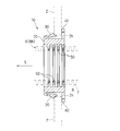
- FIG. 3 is a sectional view taken along line III-III in FIG. 2. It is detail drawing of the division member of the edge protector which concerns on 1st Embodiment. It is a perspective view of the edge protector which concerns on 2nd Embodiment.
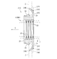
- FIG. 6 is a sectional view taken along line VI-VI in FIG. 5. It is detail drawing of the division member of the edge protector which concerns on 2nd Embodiment. It is a perspective view of the edge protector which concerns on a modification.
- the edge protector 10 is a member that protects the wire harness WH routed through the through hole 2h formed in the plate-like support 2 from the peripheral edge of the through hole 2h (see FIG. 3).
- the support 2 is, for example, a metal panel that constitutes the body of an automobile, and in a routing path or the like from the body to the door, a through hole 2h is formed to route the wire harness WH through the body. Yes.
- the peripheral edge portion of the through hole 2h has a shape in which a pair of arc-shaped portions are connected by a pair of linear portions.
- the wire harness WH to be protected by the edge protector 10 includes an electric wire 5 and a corrugated tube 6 that covers the periphery of the electric wire 5.
- the corrugated tube 6 is a protective tube for protecting the electric wire 5 from the outside. More specifically, the corrugated tube 6 is a member that is formed in a cylindrical shape and in which convex ridges 7 and concave ridges 8 along the circumferential direction are alternately continued in the axial direction.
- the corrugated tube 6 is manufactured by extruding a synthetic resin material such as polyamide (PA), polypropylene (PP), polybutylene terephthalate (PBT), ABS resin or polyethylene (PE), and blow molding or vacuum molding. It is an integrally molded member.
- the corrugated tube 6 may be formed of a relatively hard rubber (ethylene propylene diene rubber (EPDM), elastomer, or the like).
- corrugated tube 6 will be described as an example in which the corrugated tube 6 is formed in a cylindrical shape connecting a pair of arcuate portions with a pair of straight portions in a cross-sectional view orthogonal to the central axis.
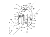
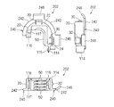
- the edge protector 10 includes a pair of divided members 102 (see FIGS. 1, 2, and 4). In FIG. 3, the shape of the divided portion of the edge protector 10 is omitted.
- the pair of divided members 102 are members that form a cylindrical shape by being sandwiched and combined from both sides of the corrugated tube 6 of the wire harness WH.
- Each of the pair of divided members 102 includes a divided main body portion 20, a locking portion 30, a pressing portion 40, and a rib 50.
- the split main body portion 20 is a portion that forms a cylindrical shape through which the corrugated tube 6 is inserted while being inserted into the through hole 2h in the combined state of the pair of split members 102.
- the pair of divided main body portions 20 whose end portions are butted together in the combined state of the pair of divided members 102 will be described.
- the pair of divided main body portions 20 are inserted into the through hole 2h of the support body 2 from one side to the other side with the support body 2 interposed therebetween.
- this direction is described as the insertion direction S, and is also used to explain the direction of the edge protector 10 itself.
- the pair of divided main body portions 20 are interposed between the wire harness WH passed through the through hole 2h of the support 2 and the peripheral portion of the through hole 2h, and the wire harness WH is a through hole in the support 2. This prevents contact with the peripheral edge of 2h and damage (see FIG. 3).
- the outer peripheral portions of the pair of divided main body portions 20 have a shape corresponding to the peripheral edge portion of the through hole 2h and are set to a size slightly smaller than the through hole 2h.
- the inner peripheral portions of the pair of divided main body portions 20 have a shape corresponding to the outer shape of the outer peripheral portion of the peak portion 7 of the corrugated tube 6 and are set to a size slightly larger than the peak portion 7.
- the corresponding shape means a shape that is substantially similar and exists along the shape of the other party as a whole.
- the pair of divided main body portions 20 are formed in a cylindrical shape that connects the pair of arc-shaped portions 22 to the pair of linear portions 24 in a cross-sectional view orthogonal to the insertion direction S. But the division
- segmentation main-body part 20 should just be formed in the shape corresponding to the outer shape of the corrugated tube 6, and the shape of the peripheral part of the through-hole 2h, and is not restricted to the said shape.
- the latching portion 30 is a portion that latches from the front side in the insertion direction S with respect to the peripheral portion of the through hole 2 h in the support 2.
- the locking portion 30 extends from the outer peripheral portion (here, the end portion on the front side in the insertion direction S) of the main body portion 20 toward the outer peripheral side and the rear side in the insertion direction S, and the tip portion thereof is a free end. It is a shape part (see FIG. 3). That is, it is formed in a shape in which the protruding dimension toward the outer peripheral side gradually increases from the front side to the rear side in the insertion direction S.
- locking part 30 has a latching surface which faces the insertion direction S back at the front-end
- the locking part 30 projects from the outer peripheral part of the divided main body part 20 to the outer peripheral side, and the locking surface comes into contact with the peripheral part of the through hole 2h in the support 2 from the front side in the insertion direction S. From the form which stops, it is comprised so that elastic deformation can be carried out to the inner peripheral side rather than it.
- locking part 30 passes the through-hole 2h of the support body 2, it contacts with the peripheral part of the through-hole 2h, and is elastically deformed to the inner peripheral side until it fits in the through-hole 2h. Furthermore, the latching
- the locking portions 30 are respectively provided at four locations of the intermediate portions of the pair of arc-shaped portions 22 and the intermediate portions of the pair of linear portions 24 (see FIG. 2). .
- locking part 30 can be latched from the insertion direction S front side with sufficient balance in the circumferential direction with respect to the peripheral part of the through-hole 2h.
- the pressing portion 40 is formed in a shape protruding from the outer peripheral portion of the divided main body portion 20 to the outer peripheral side, and is a portion facing the peripheral portion of the through hole 2h of the support 2 from the rear side in the insertion direction S.
- the holding portion 40 is a portion that protrudes from the outer peripheral portion of the divided main body portion 20 to the outer peripheral side and forms an annular shape along the peripheral edge portion of the through hole 2 h of the support body 2 in the combined state of the pair of divided members 102.
- the presser portion 40 is formed in a flat shape along a surface orthogonal to the insertion direction S.
- the pressing portion 40 is formed in a size larger than the through hole 2h.
- the presser portion 40 is provided at an end portion in the insertion direction S in the divided main body portion 20 (see FIG. 3).
- the rib 50 is a portion that is formed in a protruding line that protrudes from the inner peripheral portion of the divided main body portion 20 toward the inner peripheral side along the circumferential direction.
- This rib 50 is a part which fits into the trough part 8 in the outer peripheral part of the corrugated tube 6 of the wire harness WH passed through the inside of the divided main body part 20 (see FIG. 3).
- a plurality of ribs 50 are provided at intervals at which the valley portions 8 of the corrugated tube 6 are provided.
- the protruding dimension of the rib 50 is set to a dimension that is the same as or smaller (smaller here) than the height difference between the peak 7 and the valley 8 of the corrugated tube 6.
- the width dimension of the rib 50 is set to a dimension that is the same as or smaller (smaller here) than the interval between the adjacent peaks 7 in the corrugated tube 6.
- the pair of split members 102 are formed in the same shape. Further, the split member 102 includes a short leg portion 104, a long leg portion 106 that is longer than the short leg portion 104 and includes the straight portion 24 of the split main body portion 20, and a curved portion 108 that includes the arcuate portion 22 of the split main body portion 20. It is formed in the shape which has (substantially J shape).
- the locking portion 30 is provided at a position corresponding to the intermediate portion of the pair of arc-shaped portions 22 and the intermediate portion of the pair of linear portions 24 in the circumferential direction of the divided main body portion 20.
- the division member 102 was provided in each intermediate
- the two locking portions 30 are manufactured integrally by injection molding or the like.
- the pair of split members 102 are provided with a lock mechanism that maintains a combined state.
- This locking mechanism is configured by an arm portion 114 provided at one end of the split member 102 and a receiving portion 116 that the arm portion 114 engages with the other end.
- the arm portion 114 is provided on the long leg portion 106
- the receiving portion 116 is provided on the short leg portion 104.
- the arm portion 114 has a protruding portion 115 that protrudes from one end portion of the dividing member 102 and protrudes from the tip end portion of the protruding piece toward the inner peripheral side of the dividing main body portion 20.
- the receiving portion 116 is formed in a concave shape that opens at the other end portion of the dividing member 102 and into which the arm portion 114 is inserted, and has a hole portion 117 into which the protruding portion 115 is fitted. That is, the hole 117 is formed in a shape that is recessed toward the inner peripheral side of the divided main body 20. Here, the hole 117 penetrates into the internal space of the divided main body 20.
- the projections 115 of the arm portions 114 of the one split member 102 are fitted into the holes 117 of the receiving portions 116 of the other split member 102, respectively.
- the united state of the split member 102 is maintained. More specifically, since the corrugated tube 6 is interposed between the pair of divided members 102 in a state where the projection 115 is fitted in the hole 117, the inner periphery of the divided member 102 in the receiving portion 116. The side portion is restricted from being deformed to the inner peripheral side.
- the movement of the arm portion 114 toward the outer peripheral side of the split member 102 is restricted when the portion of the arm portion 114 opposite to the protruding direction of the protruding portion 115 contacts the inner wall portion of the receiving portion 116. Thereby, the state which the arm part 114 latched to the receiving part 116 is maintained more reliably.
- the combination of the shapes of the arm part 114 and the receiving part 116 is preferable, but the protrusion 115 and the hole 117 protrude or dent on the outer peripheral side of the pair of split members 102. It may be formed in a shape.
- the locking portion 30 is provided at the end portion on the front side in the insertion direction S of the divided main body portion 20 and the holding portion 40 is provided at the end portion on the rear side in the insertion direction S of the divided main body portion 20
- the locking part 30 and the pressing part 40 may be provided in the middle part in the insertion direction S of the divided main body part 20.
- the edge protector 10 is constituted by a pair of divided members 102 that form a cylindrical shape by being sandwiched and combined from both sides of the corrugated tube 6.
- the pair of dividing members 102 are inserted into the through hole 2h of the support 2 and have a divided main body portion 20 that forms a cylindrical shape through which the corrugated tube 6 passes, and a divided main body with respect to the peripheral edge portion of the through hole 2h.
- the locking part 30 which locks from the insertion direction S front side of the part 20 and the pressing part 40 which opposes from the insertion direction S rear side with respect to the peripheral part of the through-hole 2h are provided. Thereby, the escape from the through-hole 2h is suppressed and attached to the support body 2.
- ribs 50 formed on the protruding ridges projecting from the inner peripheral portion of the divided main body portion 20 along the circumferential direction to the inner peripheral side are provided, and the ribs 50 are corrugated tube by the combined operation of the pair of divided members 102. 6, the edge protector 10 can be easily mounted while being positioned relative to the corrugated tube 6.
- both members can be formed with a single mold. Therefore, the equipment introduction cost accompanying the design and manufacture of the mold can be reduced. In addition, since one type of part is handled, it contributes to improvement in manageability and workability.
- the split main body 20 is formed in a cylindrical shape that connects the pair of arcuate portions 22 with the pair of linear portions 24 in a cross-sectional view orthogonal to the insertion direction S in the combined state of the pair of split members 102. Even if the locking portion 30 is provided so as to be positioned at an intermediate portion of the straight portion 24, the dividing member 102 has the long leg portion 106 including the short leg portion 104 and the straight portion 24, the short leg portion 104, and the long leg portion 106. Therefore, the pair of divided members 102 can be formed in the same shape.
- the pair of divided members 102 since the pair of divided members 102 has the arm portion 114 at one end portion and the receiving portion 116 to which the arm portion 114 is locked at the other end portion, the pair of divided members 102 are corrugated.
- the united state across the tube 6 can be maintained by itself.
- the arm portion 114 protrudes from one end portion of the dividing member 102 and has a protruding portion 115 protruding toward the inner peripheral side of the dividing main body portion 20, and the receiving portion 116 opens at the other end portion of the dividing member 102. And has a hole 117 into which the protruding portion 115 is fitted.
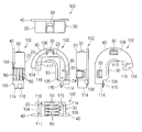
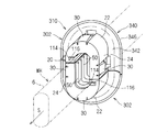
- the edge protector 210 according to the second embodiment will be described (see FIGS. 5 to 7).
- the edge protector 210 is different only in that the presser part 240 includes the split hook part 242 and the urging part 246.
- the reference numerals are attached and the description is omitted.
- the split collar portion 242 of the presser portion 240 is a portion formed in the same shape as the presser portion 40 according to the first embodiment, and faces the through hole 2h of the support body 2 from the rear side in the insertion direction S.
- the urging portion 246 is a portion that sandwiches the support 2 with the locking portion 30 in the insertion direction S (see FIGS. 5 and 6).
- the urging portion 246 is formed in a shape projecting from the split flange portion 242 to the outer peripheral side and the front side in the insertion direction S, and the tip end portion is a free end.
- the urging portion 246 protrudes from the outer peripheral portion of the split collar portion 242 and is formed in a shape that gradually tilts toward the front side in the insertion direction S toward the outer peripheral side. Accordingly, the biasing portion 246 is configured such that the tip side portion can be elastically deformed to the rear side in the insertion direction S from the above form.
- the urging portion 246 is formed in a shape in which the distal end portion is positioned at an interval smaller than the thickness dimension of the support 2 with respect to the locking surface (tip portion) of the locking portion 30 in the insertion direction S. And the urging
- the support body 2 is pressed against the surface on the rear side in the insertion direction S and elastically deforms rearward in the insertion direction S (see FIG. 6).
- biasing part 246 is the state which urged
- a plurality of urging portions 246 are provided at equal intervals in the circumferential direction of the split collar portion 242 (see FIG. 5).
- the urging portion 246 is provided at a position corresponding to the locking portion 30 in the circumferential direction of the divided collar portion 242. That is, the urging portion 246 is provided at a position corresponding to each intermediate portion of the pair of arcuate portions 22 and the pair of straight portions 24 of the divided main body portion 20 in the circumferential direction of the divided collar portion 242.
- the division member 202 respond
- the two locking portions 30 and the two biasing portions 246 provided at the positions are integrally formed by injection molding or the like (see FIG. 7).
- the urging portion is not limited to a shape that gradually inclines toward the front side in the insertion direction S toward the outer peripheral side, and is in surface contact with the surface on the rear side in the insertion direction S of the support body 2 at the tip end portion (outer peripheral side portion). It may have a flat portion, or may be formed in a cross-sectional mountain shape in which an intermediate portion between the proximal end portion and the distal end portion protrudes forward in the insertion direction S. Further, the configuration in which the urging portions 246 are provided at four locations has been described so far, but the configuration is not limited thereto. For example, the urging portion 246 is the center of the divided main body portion 20 in the combined state of the pair of dividing members 202. You may be provided in two places which oppose on both sides of an axis
- the shape of the presser part 340 having an urging part 346 that forms an annular shape that is continuous in the circumferential direction of the divided hook part 342 can also be adopted.
- the split hook part 342 of the presser part 340 has the same shape as the split hook part 242 of the presser part 240 described above.
- the urging portion 346 is formed in a shape in which the above-described urging portion 246 is continuous over the entire circumferential direction of the split collar portion 342.
- the divided member 302 is manufactured by integrally forming the divided main body portion 20, the presser portion 340, and the rib 50 divided into a substantially J shape by injection molding or the like. When this shape is adopted, rattling with respect to the support 2 can be more reliably suppressed.
- the presser portion 240 has a split collar portion 242 that forms a ring projecting from the outer peripheral portion of the split main body portion 20 to the outer peripheral side in the combined state of the pair of split members 202, and the split It has an urging portion 246 that protrudes from the position of the flange portion 242 toward the front side in the insertion direction S and is elastically deformable on the rear side in the insertion direction S. And since the support body 2 is pinched
- the amount of the material used is reduced with respect to the support body 2. Shaking can be suppressed.
- edge protector has been described in detail as described above, the above description is an example in all aspects, and the present invention is not limited thereto. It is understood that countless variations that are not illustrated can be envisaged without departing from the scope of the present invention.
Landscapes
- Engineering & Computer Science (AREA)
- Architecture (AREA)
- Civil Engineering (AREA)
- Structural Engineering (AREA)
- Mechanical Engineering (AREA)
- Details Of Indoor Wiring (AREA)
- Supports For Pipes And Cables (AREA)
- Installation Of Indoor Wiring (AREA)
Abstract
L'invention concerne un élément de protection pour faisceau de câbles composé d'une paire d'éléments séparés qui réalisent une forme cylindrique après avoir été montés en sandwich depuis les deux côtés d'un tube strié de manière à être réunis. La paire d'éléments séparés comprend : une partie corps séparé qui réalise une forme cylindrique qui s'insère dans un trou traversant d'un corps support et à travers l'intérieur de laquelle passe le tube strié ; une partie verrouillage qui est réalisée dans une forme qui se projette depuis la périphérie extérieure de la partie corps séparé vers le côté périphérique extérieur et qui est capable de se déformer par flexibilité d'une forme verrouillée depuis le côté avant dans le sens de l'insertion par rapport à la périphérie du trou traversant vers le côté périphérique intérieur ; une partie de maintien qui est réalisée dans une forme qui se projette depuis la périphérie extérieure de la partie corps séparé vers le côté périphérique extérieur et qui fait face depuis le côté arrière dans le sens de l'insertion par rapport à la périphérie du trou traversant ; et des nervures qui sont formées dans les stries qui font saillie depuis la périphérie intérieure de la partie corps séparé vers le côté périphérique intérieur dans une direction circonférentielle et qui s'accouplent avec le tube strié.
Applications Claiming Priority (2)
| Application Number | Priority Date | Filing Date | Title |
|---|---|---|---|
| JP2011-060655 | 2011-03-18 | ||
| JP2011060655A JP2012200037A (ja) | 2011-03-18 | 2011-03-18 | ワイヤーハーネスの保護具 |
Publications (1)
| Publication Number | Publication Date |
|---|---|
| WO2012127721A1 true WO2012127721A1 (fr) | 2012-09-27 |
Family
ID=46878911
Family Applications (1)
| Application Number | Title | Priority Date | Filing Date |
|---|---|---|---|
| PCT/JP2011/073496 Ceased WO2012127721A1 (fr) | 2011-03-18 | 2011-10-13 | Élément de protection pour faisceau de câbles |
Country Status (2)
| Country | Link |
|---|---|
| JP (1) | JP2012200037A (fr) |
| WO (1) | WO2012127721A1 (fr) |
Cited By (1)
| Publication number | Priority date | Publication date | Assignee | Title |
|---|---|---|---|---|
| CN115483652A (zh) * | 2021-06-15 | 2022-12-16 | 住友电装株式会社 | 线束 |
Families Citing this family (3)
| Publication number | Priority date | Publication date | Assignee | Title |
|---|---|---|---|---|
| JP6078912B2 (ja) * | 2013-03-29 | 2017-02-15 | パナソニックIpマネジメント株式会社 | 設置構造 |
| JP6454110B2 (ja) * | 2014-09-12 | 2019-01-16 | ポップリベット・ファスナー株式会社 | 防振クランプ |
| JP2023010275A (ja) * | 2021-07-09 | 2023-01-20 | 矢崎総業株式会社 | 電線カバー |
Citations (4)
| Publication number | Priority date | Publication date | Assignee | Title |
|---|---|---|---|---|
| JPS6427918U (fr) * | 1987-08-10 | 1989-02-17 | ||
| JPH0160583U (fr) * | 1987-10-12 | 1989-04-17 | ||
| JPH0536720U (ja) * | 1991-10-18 | 1993-05-18 | 矢崎総業株式会社 | 2分割グロメツトインナ |
| JPH11155225A (ja) * | 1997-11-25 | 1999-06-08 | Sumitomo Wiring Syst Ltd | ワイヤーハーネス用取付具 |
-
2011
- 2011-03-18 JP JP2011060655A patent/JP2012200037A/ja not_active Withdrawn
- 2011-10-13 WO PCT/JP2011/073496 patent/WO2012127721A1/fr not_active Ceased
Patent Citations (4)
| Publication number | Priority date | Publication date | Assignee | Title |
|---|---|---|---|---|
| JPS6427918U (fr) * | 1987-08-10 | 1989-02-17 | ||
| JPH0160583U (fr) * | 1987-10-12 | 1989-04-17 | ||
| JPH0536720U (ja) * | 1991-10-18 | 1993-05-18 | 矢崎総業株式会社 | 2分割グロメツトインナ |
| JPH11155225A (ja) * | 1997-11-25 | 1999-06-08 | Sumitomo Wiring Syst Ltd | ワイヤーハーネス用取付具 |
Cited By (2)
| Publication number | Priority date | Publication date | Assignee | Title |
|---|---|---|---|---|
| CN115483652A (zh) * | 2021-06-15 | 2022-12-16 | 住友电装株式会社 | 线束 |
| JP2022191064A (ja) * | 2021-06-15 | 2022-12-27 | 住友電装株式会社 | ワイヤハーネス |
Also Published As
| Publication number | Publication date |
|---|---|
| JP2012200037A (ja) | 2012-10-18 |
Similar Documents
| Publication | Publication Date | Title |
|---|---|---|
| JP2010159843A (ja) | ボルト用クリップ | |
| JP4814947B2 (ja) | コルゲートチューブの接続部材 | |
| WO2013031260A1 (fr) | Dispositif de protection de faisceau et section formant structure de passage de faisceau de câble | |
| JP6155246B2 (ja) | グロメット | |
| JP2007306776A (ja) | ワイヤハーネス用プロテクタ | |
| JP6401767B2 (ja) | 車体構造 | |
| CN109863658B (zh) | 线束模块 | |
| JP6970064B2 (ja) | グロメット | |
| JP6978389B2 (ja) | グロメット | |
| JP5758645B2 (ja) | グロメット | |
| JP6309298B2 (ja) | グロメットインナー及びワイヤーハーネス | |
| JP6752257B2 (ja) | インナー付きグロメット | |
| WO2012127721A1 (fr) | Élément de protection pour faisceau de câbles | |
| CN108767538B (zh) | 索环 | |
| JP6752256B2 (ja) | インナー付きグロメット | |
| JP6329919B2 (ja) | 車両用内装部品 | |
| JP5761052B2 (ja) | グロメット | |
| JP2012175718A (ja) | グロメット | |
| JP2010283935A (ja) | ワイヤハーネスとプロテクタの取付構造 | |
| JP5765254B2 (ja) | グロメット | |
| JP5742573B2 (ja) | グロメット | |
| CN108749741B (zh) | 索环 | |
| JP2016025667A (ja) | グロメット及びグロメット付ワイヤーハーネス | |
| WO2012111179A1 (fr) | Outil de protection de faisceau de câble | |
| JP2014204530A (ja) | グロメット及びワイヤーハーネス |
Legal Events
| Date | Code | Title | Description |
|---|---|---|---|
| 121 | Ep: the epo has been informed by wipo that ep was designated in this application |
Ref document number: 11861676 Country of ref document: EP Kind code of ref document: A1 |
|
| NENP | Non-entry into the national phase |
Ref country code: DE |
|
| 122 | Ep: pct application non-entry in european phase |
Ref document number: 11861676 Country of ref document: EP Kind code of ref document: A1 |