WO2012127929A1 - Élément de diffraction optique et endoscope - Google Patents
Élément de diffraction optique et endoscope Download PDFInfo
- Publication number
- WO2012127929A1 WO2012127929A1 PCT/JP2012/053096 JP2012053096W WO2012127929A1 WO 2012127929 A1 WO2012127929 A1 WO 2012127929A1 JP 2012053096 W JP2012053096 W JP 2012053096W WO 2012127929 A1 WO2012127929 A1 WO 2012127929A1
- Authority
- WO
- WIPO (PCT)
- Prior art keywords
- optical material
- optical element
- conditional expression
- following conditional
- diffractive optical
- Prior art date
- Legal status (The legal status is an assumption and is not a legal conclusion. Google has not performed a legal analysis and makes no representation as to the accuracy of the status listed.)
- Ceased
Links
Images

Classifications
-
- G—PHYSICS
- G02—OPTICS
- G02B—OPTICAL ELEMENTS, SYSTEMS OR APPARATUS
- G02B27/00—Optical systems or apparatus not provided for by any of the groups G02B1/00 - G02B26/00, G02B30/00
- G02B27/42—Diffraction optics, i.e. systems including a diffractive element being designed for providing a diffractive effect
- G02B27/4205—Diffraction optics, i.e. systems including a diffractive element being designed for providing a diffractive effect having a diffractive optical element [DOE] contributing to image formation, e.g. whereby modulation transfer function MTF or optical aberrations are relevant
-
- A—HUMAN NECESSITIES
- A61—MEDICAL OR VETERINARY SCIENCE; HYGIENE
- A61B—DIAGNOSIS; SURGERY; IDENTIFICATION
- A61B1/00—Instruments for performing medical examinations of the interior of cavities or tubes of the body by visual or photographical inspection, e.g. endoscopes; Illuminating arrangements therefor
- A61B1/00064—Constructional details of the endoscope body
- A61B1/00071—Insertion part of the endoscope body
- A61B1/0008—Insertion part of the endoscope body characterised by distal tip features
- A61B1/00096—Optical elements
-
- A—HUMAN NECESSITIES
- A61—MEDICAL OR VETERINARY SCIENCE; HYGIENE
- A61B—DIAGNOSIS; SURGERY; IDENTIFICATION
- A61B1/00—Instruments for performing medical examinations of the interior of cavities or tubes of the body by visual or photographical inspection, e.g. endoscopes; Illuminating arrangements therefor
- A61B1/00064—Constructional details of the endoscope body
- A61B1/0011—Manufacturing of endoscope parts
-
- A—HUMAN NECESSITIES
- A61—MEDICAL OR VETERINARY SCIENCE; HYGIENE
- A61B—DIAGNOSIS; SURGERY; IDENTIFICATION
- A61B1/00—Instruments for performing medical examinations of the interior of cavities or tubes of the body by visual or photographical inspection, e.g. endoscopes; Illuminating arrangements therefor
- A61B1/00163—Optical arrangements
-
- G—PHYSICS
- G02—OPTICS
- G02B—OPTICAL ELEMENTS, SYSTEMS OR APPARATUS
- G02B27/00—Optical systems or apparatus not provided for by any of the groups G02B1/00 - G02B26/00, G02B30/00
- G02B27/0025—Optical systems or apparatus not provided for by any of the groups G02B1/00 - G02B26/00, G02B30/00 for optical correction, e.g. distorsion, aberration
- G02B27/0037—Optical systems or apparatus not provided for by any of the groups G02B1/00 - G02B26/00, G02B30/00 for optical correction, e.g. distorsion, aberration with diffracting elements
-
- G—PHYSICS
- G02—OPTICS
- G02B—OPTICAL ELEMENTS, SYSTEMS OR APPARATUS
- G02B23/00—Telescopes, e.g. binoculars; Periscopes; Instruments for viewing the inside of hollow bodies; Viewfinders; Optical aiming or sighting devices
- G02B23/24—Instruments or systems for viewing the inside of hollow bodies, e.g. fibrescopes
- G02B23/2407—Optical details
-
- G—PHYSICS
- G02—OPTICS
- G02B—OPTICAL ELEMENTS, SYSTEMS OR APPARATUS
- G02B27/00—Optical systems or apparatus not provided for by any of the groups G02B1/00 - G02B26/00, G02B30/00
- G02B27/0018—Optical systems or apparatus not provided for by any of the groups G02B1/00 - G02B26/00, G02B30/00 with means for preventing ghost images
Definitions
- the present invention relates to a diffractive optical element and an endoscope.
- the diffractive optical element of Patent Document 1 is not laminated, the diffraction efficiency strongly depends on the wavelength, and if incorporated in an endoscope (a flexible mirror or a rigid mirror), a factor that causes flare on the contrary. There is an inconvenience that it becomes. Further, the diffractive optical elements of Patent Documents 2 and 3 are laminated with optical elements on which relief patterns are formed. Thereby, high diffraction efficiency of the first-order diffracted light (hereinafter simply referred to as diffraction efficiency) can be achieved in a wide wavelength range. However, since one of the two layers of optical elements is made of a glass material, the relief pattern However, there are disadvantages in that it is difficult to process, is not mass-productive and is expensive.
- Patent Documents 4 to 7 are made of resin, they are excellent in processability and mass productivity and can be manufactured at low cost.
- the condition of the thickness of the medium is not appropriate, and warping occurs in the manufacturing process. And inconvenience that peeling easily occurs.
- an object of the present invention is to provide a diffractive optical element and an endoscope that can be applied to an endoscope at low cost.
- the present invention provides a diffractive optical element in which two optical material layers made of different energy curable resins are laminated, a relief pattern is formed on the boundary surface between the two optical material layers, and the following conditional expression is satisfied. . 0.01 ⁇ d 2 / d 1 ⁇ 0.2 (1) 0.05 ⁇ d 1 / ⁇ E ⁇ 1.0 (2) 0.0005 ⁇ d 2 / ⁇ E ⁇ 0.1 (3)
- d 1 center thickness (mm) of one optical material layer cured first
- d 2 center thickness (mm) of the other optical material layer cured later
- ⁇ E effective diameter of relief pattern (Mm).
- ⁇ ⁇ By laminating optical material layers, diffraction efficiency can be increased in a wide wavelength range. And by comprising an optical material layer with an energy hardening resin, workability and mass productivity can be improved and cost reduction can be aimed at. By forming a relief pattern on the boundary surface between two optical material layers, a diffractive optical element having a light condensing function such as a lens can be manufactured.
- the ratio of the thickness of the optical material layer to be cured first and the optical material layer to be cured later is set to an appropriate ratio so that the warp of the optical material layer Generation
- the thickness of the optical material layer that is cured later becomes excessively large, and a large stress is generated to cause warping and peeling.
- the lower limit of conditional expression (1) is exceeded, the thickness of the optical material layer that will be cured later becomes too small, and the workability and mass productivity decrease.
- conditional expressions (2) and (3) the ratio of the medium thickness becomes appropriate, and warping and peeling are less likely to occur.
- the upper limit of conditional expressions (2) and (3) the inner thickness of the optical material layer becomes too large and a large stress is generated, so that warping and peeling are likely to occur.
- the lower limit of conditional expressions (2) and (3) the inner thickness of the optical material layer becomes too small, and the workability and mass productivity decrease.
- n 1 is the refractive index of the one optical material layer at the d-line
- n 2 is the refractive index of the other optical material layer at the d-line.
- conditional expressions 10 ⁇ 1 ⁇ 50 (6) 10 ⁇ 2 ⁇ 50 (7)
- ⁇ 1 is the Abbe number of one of the optical material layers
- ⁇ 2 is the Abbe number of the other optical material layer.
- the relief pattern has a pitch that gradually decreases from the center to the periphery of the optical material layer, and the depth of the groove is constant throughout, and satisfies the following conditional expression: Is preferred. 0.8 ⁇ M 1 ⁇
- M 1 is the depth of the groove of the relief pattern
- n 1 is the refractive index of one optical material layer at the d-line
- n 2 is the refractive index of the other optical material layer at the d-line
- ⁇ d is It is the wavelength of d-line.
- conditional expression (8) By satisfying conditional expression (8), the depth of the groove becomes appropriate, and a diffractive optical element having high diffraction efficiency in a wide wavelength region can be manufactured. When the conditional expression (8) is not satisfied, the wavelength region having high diffraction efficiency is narrowed.
- n 1 is the refractive index of the one optical material layer at the d-line
- n 2 is the refractive index of the other optical material layer at the d-line.
- conditional expression (9) When the conditional expression (9) is satisfied, the refractive index difference of the energy curable resin constituting the optical material layer is appropriate. Exceeding the upper limit of conditional expression (9) makes it difficult to procure energy curable resin. If the lower limit of conditional expression (9) is exceeded, the depth of the groove becomes too deep and machining becomes extremely difficult.
- conditional expression (10) the Abbe number of one of the optical material layers
- ⁇ 2 the Abbe number of the other optical material layer.
- conditional expression (10) the Abbe number difference of the energy curable resin constituting the optical material layer is appropriate. If the conditional expression (10) is not satisfied, it is extremely difficult to procure energy curable resin.
- the diffraction efficiency of the first-order diffracted light is preferably 75% or more in the wavelength region of 400 to 700 nm.
- the optical material layer may be an ultraviolet curable resin, a thermosetting resin, or a thermoplastic resin.
- the present invention also provides an endoscope including any one of the above diffractive optical elements.
- an image pickup device for photographing light transmitted through the diffractive optical element is provided and the following conditional expression is satisfied.
- ccd_pitch the pixel pitch of the image sensor.
- the wavelength dependence of diffraction efficiency is reduced, and flare caused by unnecessary-order light other than the first-order diffracted light is prevented, and it is applied to an endoscope at a low cost while preventing warping and peeling. There is an effect that can be.
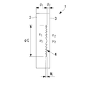
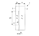
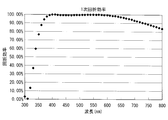
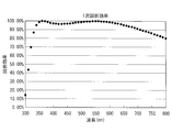
- FIG. 2 is a longitudinal sectional view showing a first embodiment of the diffractive optical element in FIG. 1. It is a longitudinal cross-sectional view which shows the 2nd Example of the diffractive optical element of FIG. It is a figure which shows the graph of the wavelength characteristic of the diffraction efficiency in the 1st Example of the diffractive optical element of FIG. It is a figure which shows the graph of the wavelength characteristic of the diffraction efficiency in the 2nd Example of the diffractive optical element of FIG.
- the diffractive optical element 1 according to the present embodiment is a multilayer diffractive optical element 1 in which a first optical material layer 2 and a second optical material layer 3 are laminated as shown in FIG.
- the two optical material layers 2 and 3 are made of different energy curable resins.
- the first optical material layer 2 is an optical material layer that is cured first, and has a center thickness d 1 , a refractive index n 1 at d-line, and an Abbe number ⁇ 1 .
- the second optical material layer 3 is an optical material layer that is cured later, and has a center thickness d 2 , a refractive index n 2 at d-line, and an Abbe number ⁇ 2 .
- a relief pattern 4 is formed on the boundary surface between the first optical material layer 2 and the second optical material layer 3.
- the relief pattern 4 has concavities and convexities in which the pitch gradually decreases from the center outward in the radial direction.
- the depth M 1 of the relief pattern 4 is approximately constant over the entire relief pattern 4, the effective diameter of the relief pattern 4 is .phi.E.
- the diffractive optical element 1 according to the present embodiment configured as described above has the following effects.
- the diffraction efficiency can be increased in a wide wavelength range.
- the two optical material layers 2 and 3 with an energy curable resin, it is possible to improve processability and mass productivity and to reduce costs.
- the relief pattern 4 on the boundary surface between the two optical material layers 2 and 3, it is possible to manufacture the diffractive optical element 1 having a condensing function like a lens.
- conditional expression (1) the ratio of the thickness of the optical material layer 2 to be cured first and the thickness of the optical material layer 3 to be cured later is set to an appropriate ratio, so that the optical material layer 2 , 3 can be prevented from warping and peeling.
- the thickness of the optical material layer 3 to be cured later becomes excessively large, and a large stress is generated to cause warping and peeling.
- the lower limit of conditional expression (1) is exceeded, the thickness of the optical material layer 3 that will be cured later becomes too small, and workability and mass productivity are reduced.
- conditional expressions (2) and (3) the ratio of the medium thickness becomes appropriate, and warping and peeling are less likely to occur. If the upper limit of conditional expressions (2) and (3) is exceeded, the thickness of the optical material layers 2 and 3 becomes too large and a large stress is generated, so that warping and peeling are likely to occur. If the lower limit of conditional expressions (2) and (3) is exceeded, the thickness of the optical material layers 2 and 3 will be too small, and workability and mass productivity will deteriorate.
- conditional expressions (4), (5), (6), and (7) the energy curable resin constituting the optical material layers 2 and 3 can be procured.
- conditional expression (8) the depth of the groove becomes appropriate, and the diffractive optical element 1 having high diffraction efficiency in a wide wavelength region can be manufactured.
- conditional expression (8) is not satisfied, the wavelength region having high diffraction efficiency is narrowed.
- conditional expression (9) the difference in refractive index between the energy curable resins constituting the optical material layers 2 and 3 is appropriate.
- Exceeding the upper limit of conditional expression (9) makes it difficult to procure energy curable resin.
- the lower limit of the conditional expression (9) processed too deep depth M 1 of the groove becomes extremely difficult.
- conditional expression (10) the Abbe number difference between the energy curable resins constituting the optical material layers 2 and 3 is appropriate. If the conditional expression (10) is not satisfied, it is extremely difficult to procure energy curable resin.
- conditional expressions (1 ′), (2 ′), (3 ′) are satisfied instead of the conditional expressions (1), (2), (3), More preferably, the conditional expressions (1 ′′), (2 ′′), and (3 ′′) are satisfied.
- conditional expressions (4 ′) and (5 ′) are satisfied instead of the conditional expressions (4) and (5), and the conditional expressions (4 ′′) and (5 ′) It is further preferable to satisfy “)”. 1.55 ⁇ n 1 ⁇ 1.75 (4 ′) 1.55 ⁇ n 2 ⁇ 1.75 (5 ′)
- conditional expressions (6 ′) and (7 ′) are satisfied instead of the conditional expressions (6) and (7), and the conditional expressions (6 ′′) and (7 It is further preferable to satisfy “)”. 13 ⁇ 1 ⁇ 45 (6 ′) 13 ⁇ 2 ⁇ 45 (7 ′)
- conditional expression (9 ′) is satisfied instead of conditional expression (9), and it is more preferable that conditional expression (9 ′′) is satisfied. 0.0005 ⁇
- conditional expression (10 ′) instead of the conditional expression (10), and it is more preferable to satisfy the conditional expression (10 ′′).
- the pixel pitch ccd_pitch of the imaging element provided in the endoscope and the depth M 1 of the relief pattern 4 of the diffractive optical element 1 And satisfy the relationship of the conditional expression (11). 0.1 ⁇ M 1 / ccd_pitch ⁇ 200 (11)
- conditional expression (11) there is an advantage that the depth M 1 of the relief pattern 4 can be suppressed within an appropriate range and the workability can be improved.
- the first optical material layer 2 is an energy curable resin “MR-7 manufactured by Mitsui Chemicals”
- the second optical material layer 3 is “UV-made by Mitsubishi Chemical Corporation”.
- An energy curable resin of “1000” is used.
- the first optical material layer 2 is an energy curable resin called “MIU-L2000” manufactured by MGC
- the second optical material layer 3 is “EP-5000” manufactured by MGC.
- the energy curable resin is used.
- FIG. 4 shows the wavelength characteristics of the diffraction efficiency of the diffractive optical element 1 of the first example (Example 1).
- FIG. 5 shows the wavelength characteristics of the diffraction efficiency of the diffractive optical element 1 of the second example (Example 2). According to these figures, it can be seen that in any case, a diffraction efficiency of 75% or more is maintained in the wavelength region of 400 to 700 nm. As a result, the wavelength dependency of diffraction efficiency is reduced, and there is an advantage that flare can be reduced even when incorporated in an endoscope (soft mirror or rigid mirror: not shown).
- Table 1 shows values obtained by applying the coefficients and conditional expressions (1) to (11) in Example 1 and Example 2. According to Table 1, both diffractive optical elements of Example 1 and Example 2 satisfy all conditional expressions (1) to (11).
Landscapes
- Health & Medical Sciences (AREA)
- Life Sciences & Earth Sciences (AREA)
- Physics & Mathematics (AREA)
- Surgery (AREA)
- Optics & Photonics (AREA)
- Engineering & Computer Science (AREA)
- Heart & Thoracic Surgery (AREA)
- Animal Behavior & Ethology (AREA)
- Radiology & Medical Imaging (AREA)
- Nuclear Medicine, Radiotherapy & Molecular Imaging (AREA)
- Biophysics (AREA)
- Biomedical Technology (AREA)
- Veterinary Medicine (AREA)
- Medical Informatics (AREA)
- Molecular Biology (AREA)
- Pathology (AREA)
- General Health & Medical Sciences (AREA)
- Public Health (AREA)
- General Physics & Mathematics (AREA)
- Manufacturing & Machinery (AREA)
- Diffracting Gratings Or Hologram Optical Elements (AREA)
- Lenses (AREA)
- Endoscopes (AREA)
- Instruments For Viewing The Inside Of Hollow Bodies (AREA)
Abstract
Priority Applications (4)
| Application Number | Priority Date | Filing Date | Title |
|---|---|---|---|
| CN201280002380.1A CN103080786B (zh) | 2011-03-18 | 2012-02-10 | 衍射光学元件及内窥镜 |
| JP2012545968A JP5159998B2 (ja) | 2011-03-18 | 2012-02-10 | 回折光学素子および内視鏡 |
| EP12761223.2A EP2581768A4 (fr) | 2011-03-18 | 2012-02-10 | Élément de diffraction optique et endoscope |
| US13/633,522 US8531511B2 (en) | 2011-03-18 | 2012-10-02 | Diffractive optical element and endoscope |
Applications Claiming Priority (2)
| Application Number | Priority Date | Filing Date | Title |
|---|---|---|---|
| JP2011-061320 | 2011-03-18 | ||
| JP2011061320 | 2011-03-18 |
Related Child Applications (1)
| Application Number | Title | Priority Date | Filing Date |
|---|---|---|---|
| US13/633,522 Continuation US8531511B2 (en) | 2011-03-18 | 2012-10-02 | Diffractive optical element and endoscope |
Publications (1)
| Publication Number | Publication Date |
|---|---|
| WO2012127929A1 true WO2012127929A1 (fr) | 2012-09-27 |
Family
ID=46879096
Family Applications (1)
| Application Number | Title | Priority Date | Filing Date |
|---|---|---|---|
| PCT/JP2012/053096 Ceased WO2012127929A1 (fr) | 2011-03-18 | 2012-02-10 | Élément de diffraction optique et endoscope |
Country Status (5)
| Country | Link |
|---|---|
| US (1) | US8531511B2 (fr) |
| EP (1) | EP2581768A4 (fr) |
| JP (1) | JP5159998B2 (fr) |
| CN (1) | CN103080786B (fr) |
| WO (1) | WO2012127929A1 (fr) |
Families Citing this family (5)
| Publication number | Priority date | Publication date | Assignee | Title |
|---|---|---|---|---|
| WO2015124159A1 (fr) | 2014-02-21 | 2015-08-27 | 3Dintegrated Aps | Ensemble comprenant un instrument chirurgical |
| US11020144B2 (en) | 2015-07-21 | 2021-06-01 | 3Dintegrated Aps | Minimally invasive surgery system |
| JP6776327B2 (ja) | 2015-07-21 | 2020-10-28 | スリーディインテグレイテッド アーペーエス3Dintegrated Aps | カニューレアセンブリキット、套管針アセンブリキット、スリーブアセンブリ、低侵襲性手術システム及び方法 |
| DK178899B1 (en) | 2015-10-09 | 2017-05-08 | 3Dintegrated Aps | A depiction system |
| CN107300731A (zh) * | 2017-07-25 | 2017-10-27 | 华天科技(昆山)电子有限公司 | 衍射光学元件结构及制作方法 |
Citations (11)
| Publication number | Priority date | Publication date | Assignee | Title |
|---|---|---|---|---|
| JPH02179605A (ja) | 1988-10-31 | 1990-07-12 | Univ Rochester | 像形成用回折光学素子の収差を低減する方法とそのための光学系 |
| JPH11271513A (ja) | 1998-03-23 | 1999-10-08 | Minolta Co Ltd | 回折光学素子 |
| JPH11287904A (ja) | 1998-04-01 | 1999-10-19 | Olympus Optical Co Ltd | 回折光学素子及びその製造方法 |
| JP2005107298A (ja) | 2003-09-30 | 2005-04-21 | Nikon Corp | 回折光学素子及び回折光学素子の製造方法 |
| WO2007111077A1 (fr) | 2006-03-24 | 2007-10-04 | Matsushita Electric Industrial Co., Ltd. | Élément optique composite |
| JP2007273012A (ja) | 2006-03-31 | 2007-10-18 | Sony Corp | 回折素子、対物レンズユニット、光ピックアップ及び光ディスク装置 |
| JP2008026440A (ja) * | 2006-07-19 | 2008-02-07 | Nikon Corp | プロジェクタ光学系 |
| JP2008242391A (ja) * | 2007-03-29 | 2008-10-09 | Canon Inc | 回折光学素子とそれを用いた光学系 |
| WO2009096389A1 (fr) * | 2008-01-28 | 2009-08-06 | Nikon Corporation | Verre de lunette, élément optique de diffraction, système optique de diffraction et instrument optique |
| JP2009197217A (ja) | 2008-01-21 | 2009-09-03 | Canon Inc | 樹脂組成物およびそれにより成形された光学素子、回折光学素子及び積層型回折光学素子 |
| WO2011136015A1 (fr) * | 2010-04-27 | 2011-11-03 | オリンパスメディカルシステムズ株式会社 | Adhésif optique et endoscope l'utilisant |
Family Cites Families (10)
| Publication number | Priority date | Publication date | Assignee | Title |
|---|---|---|---|---|
| JP2000056113A (ja) * | 1998-08-06 | 2000-02-25 | Canon Inc | 回折光学素子 |
| JP3652260B2 (ja) * | 2001-03-06 | 2005-05-25 | キヤノン株式会社 | 回折光学素子、該回折光学素子を有する光学系、撮影装置、観察装置 |
| JP4006362B2 (ja) * | 2002-06-17 | 2007-11-14 | キヤノン株式会社 | 回折光学素子、及びそれを有する光学系 |
| GB0318808D0 (en) * | 2003-08-11 | 2003-09-10 | Toshiba Res Europ Ltd | An encoded carrier |
| JP4697584B2 (ja) * | 2004-03-30 | 2011-06-08 | 株式会社ニコン | 回折光学素子及び回折光学素子の製造方法 |
| JP4387855B2 (ja) * | 2004-04-01 | 2009-12-24 | キヤノン株式会社 | 光学系 |
| JP4673120B2 (ja) * | 2004-04-28 | 2011-04-20 | キヤノン株式会社 | 回折光学素子及びこれを有する光学系 |
| JP4829590B2 (ja) * | 2005-10-25 | 2011-12-07 | キヤノン株式会社 | 撮影光学系及びそれを有する撮像装置 |
| JP5137432B2 (ja) * | 2007-03-23 | 2013-02-06 | キヤノン株式会社 | 密着2層型の回折光学素子とそれを用いた光学系及び光学機器 |
| US7710651B2 (en) | 2007-03-23 | 2010-05-04 | Canon Kabushiki Kaisha | Contacting two-layer diffractive optical element |
-
2012
- 2012-02-10 WO PCT/JP2012/053096 patent/WO2012127929A1/fr not_active Ceased
- 2012-02-10 CN CN201280002380.1A patent/CN103080786B/zh not_active Expired - Fee Related
- 2012-02-10 EP EP12761223.2A patent/EP2581768A4/fr not_active Withdrawn
- 2012-02-10 JP JP2012545968A patent/JP5159998B2/ja not_active Expired - Fee Related
- 2012-10-02 US US13/633,522 patent/US8531511B2/en active Active
Patent Citations (11)
| Publication number | Priority date | Publication date | Assignee | Title |
|---|---|---|---|---|
| JPH02179605A (ja) | 1988-10-31 | 1990-07-12 | Univ Rochester | 像形成用回折光学素子の収差を低減する方法とそのための光学系 |
| JPH11271513A (ja) | 1998-03-23 | 1999-10-08 | Minolta Co Ltd | 回折光学素子 |
| JPH11287904A (ja) | 1998-04-01 | 1999-10-19 | Olympus Optical Co Ltd | 回折光学素子及びその製造方法 |
| JP2005107298A (ja) | 2003-09-30 | 2005-04-21 | Nikon Corp | 回折光学素子及び回折光学素子の製造方法 |
| WO2007111077A1 (fr) | 2006-03-24 | 2007-10-04 | Matsushita Electric Industrial Co., Ltd. | Élément optique composite |
| JP2007273012A (ja) | 2006-03-31 | 2007-10-18 | Sony Corp | 回折素子、対物レンズユニット、光ピックアップ及び光ディスク装置 |
| JP2008026440A (ja) * | 2006-07-19 | 2008-02-07 | Nikon Corp | プロジェクタ光学系 |
| JP2008242391A (ja) * | 2007-03-29 | 2008-10-09 | Canon Inc | 回折光学素子とそれを用いた光学系 |
| JP2009197217A (ja) | 2008-01-21 | 2009-09-03 | Canon Inc | 樹脂組成物およびそれにより成形された光学素子、回折光学素子及び積層型回折光学素子 |
| WO2009096389A1 (fr) * | 2008-01-28 | 2009-08-06 | Nikon Corporation | Verre de lunette, élément optique de diffraction, système optique de diffraction et instrument optique |
| WO2011136015A1 (fr) * | 2010-04-27 | 2011-11-03 | オリンパスメディカルシステムズ株式会社 | Adhésif optique et endoscope l'utilisant |
Non-Patent Citations (1)
| Title |
|---|
| See also references of EP2581768A4 |
Also Published As
| Publication number | Publication date |
|---|---|
| EP2581768A4 (fr) | 2014-12-24 |
| EP2581768A1 (fr) | 2013-04-17 |
| US20130070070A1 (en) | 2013-03-21 |
| CN103080786B (zh) | 2015-03-04 |
| US8531511B2 (en) | 2013-09-10 |
| JPWO2012127929A1 (ja) | 2014-07-24 |
| CN103080786A (zh) | 2013-05-01 |
| JP5159998B2 (ja) | 2013-03-13 |
Similar Documents
| Publication | Publication Date | Title |
|---|---|---|
| JP5137432B2 (ja) | 密着2層型の回折光学素子とそれを用いた光学系及び光学機器 | |
| JP4977275B2 (ja) | 回折格子レンズおよびそれを用いた撮像装置 | |
| JP5159998B2 (ja) | 回折光学素子および内視鏡 | |
| JP4673120B2 (ja) | 回折光学素子及びこれを有する光学系 | |
| JP5264223B2 (ja) | 回折光学素子、光学系及び光学機器 | |
| JP5960854B2 (ja) | 撮像レンズ | |
| JP4796660B2 (ja) | 2枚組撮像光学系およびそれを備えた撮像装置 | |
| JP2018141825A5 (fr) | ||
| JP5870157B2 (ja) | 撮像レンズ | |
| WO2016031586A1 (fr) | Système optique d'objectif d'endoscope | |
| JP2011039400A5 (fr) | ||
| JP5873150B2 (ja) | 撮像レンズ | |
| CN1860387A (zh) | 衍射光学元件及衍射光学元件的制造方法 | |
| JP5258204B2 (ja) | 回折光学素子とそれを用いた光学系並びに光学機器 | |
| JPWO2012176388A1 (ja) | 回折光学素子 | |
| CN1222804C (zh) | 衍射光学元件和具有相同组成的光学系统及光学设备 | |
| US20120050868A1 (en) | Diffractive optical element having high diffraction efficiency at plural wavelengths and image-pickup optical system using the same | |
| JP2011017849A (ja) | リアアタッチメントレンズ及びそれを有する撮影光学系 | |
| WO2012023275A1 (fr) | Lentille à réseau de diffraction et dispositif imageur l'utilisant | |
| JP2005164840A (ja) | 光学系及びその設計方法 | |
| JPH11223717A (ja) | 回折光学素子及びそれを用いた光学系 | |
| JP5765998B2 (ja) | 回折光学素子、光学系および光学機器 | |
| WO2011052159A1 (fr) | Lentille d'achromatisation | |
| WO2013168740A1 (fr) | Élément optique de diffraction et système optique de capture d'image | |
| JP5562755B2 (ja) | 撮像レンズおよび撮像モジュール |
Legal Events
| Date | Code | Title | Description |
|---|---|---|---|
| WWE | Wipo information: entry into national phase |
Ref document number: 201280002380.1 Country of ref document: CN |
|
| ENP | Entry into the national phase |
Ref document number: 2012545968 Country of ref document: JP Kind code of ref document: A |
|
| 121 | Ep: the epo has been informed by wipo that ep was designated in this application |
Ref document number: 12761223 Country of ref document: EP Kind code of ref document: A1 |
|
| WWE | Wipo information: entry into national phase |
Ref document number: 2012761223 Country of ref document: EP |
|
| NENP | Non-entry into the national phase |
Ref country code: DE |