WO2012128003A1 - Décélérateur cycloïde et dispositif d'entraînement de moteur dans la roue - Google Patents
Décélérateur cycloïde et dispositif d'entraînement de moteur dans la roue Download PDFInfo
- Publication number
- WO2012128003A1 WO2012128003A1 PCT/JP2012/055034 JP2012055034W WO2012128003A1 WO 2012128003 A1 WO2012128003 A1 WO 2012128003A1 JP 2012055034 W JP2012055034 W JP 2012055034W WO 2012128003 A1 WO2012128003 A1 WO 2012128003A1
- Authority
- WO
- WIPO (PCT)
- Prior art keywords
- housing
- outer pin
- cycloid
- pin
- flange portion
- Prior art date
- Legal status (The legal status is an assumption and is not a legal conclusion. Google has not performed a legal analysis and makes no representation as to the accuracy of the status listed.)
- Ceased
Links
Images

Classifications
-
- F—MECHANICAL ENGINEERING; LIGHTING; HEATING; WEAPONS; BLASTING
- F16—ENGINEERING ELEMENTS AND UNITS; GENERAL MEASURES FOR PRODUCING AND MAINTAINING EFFECTIVE FUNCTIONING OF MACHINES OR INSTALLATIONS; THERMAL INSULATION IN GENERAL
- F16H—GEARING
- F16H1/00—Toothed gearings for conveying rotary motion
- F16H1/28—Toothed gearings for conveying rotary motion with gears having orbital motion
- F16H1/32—Toothed gearings for conveying rotary motion with gears having orbital motion in which the central axis of the gearing lies inside the periphery of an orbital gear
-
- B—PERFORMING OPERATIONS; TRANSPORTING
- B60—VEHICLES IN GENERAL
- B60K—ARRANGEMENT OR MOUNTING OF PROPULSION UNITS OR OF TRANSMISSIONS IN VEHICLES; ARRANGEMENT OR MOUNTING OF PLURAL DIVERSE PRIME-MOVERS IN VEHICLES; AUXILIARY DRIVES FOR VEHICLES; INSTRUMENTATION OR DASHBOARDS FOR VEHICLES; ARRANGEMENTS IN CONNECTION WITH COOLING, AIR INTAKE, GAS EXHAUST OR FUEL SUPPLY OF PROPULSION UNITS IN VEHICLES
- B60K17/00—Arrangement or mounting of transmissions in vehicles
- B60K17/04—Arrangement or mounting of transmissions in vehicles characterised by arrangement, location or kind of gearing
- B60K17/043—Transmission unit disposed in on near the vehicle wheel, or between the differential gear unit and the wheel
- B60K17/046—Transmission unit disposed in on near the vehicle wheel, or between the differential gear unit and the wheel with planetary gearing having orbital motion
-
- B—PERFORMING OPERATIONS; TRANSPORTING
- B60—VEHICLES IN GENERAL
- B60K—ARRANGEMENT OR MOUNTING OF PROPULSION UNITS OR OF TRANSMISSIONS IN VEHICLES; ARRANGEMENT OR MOUNTING OF PLURAL DIVERSE PRIME-MOVERS IN VEHICLES; AUXILIARY DRIVES FOR VEHICLES; INSTRUMENTATION OR DASHBOARDS FOR VEHICLES; ARRANGEMENTS IN CONNECTION WITH COOLING, AIR INTAKE, GAS EXHAUST OR FUEL SUPPLY OF PROPULSION UNITS IN VEHICLES
- B60K7/00—Disposition of motor in, or adjacent to, traction wheel
- B60K7/0007—Disposition of motor in, or adjacent to, traction wheel the motor being electric
-
- B—PERFORMING OPERATIONS; TRANSPORTING
- B60—VEHICLES IN GENERAL
- B60K—ARRANGEMENT OR MOUNTING OF PROPULSION UNITS OR OF TRANSMISSIONS IN VEHICLES; ARRANGEMENT OR MOUNTING OF PLURAL DIVERSE PRIME-MOVERS IN VEHICLES; AUXILIARY DRIVES FOR VEHICLES; INSTRUMENTATION OR DASHBOARDS FOR VEHICLES; ARRANGEMENTS IN CONNECTION WITH COOLING, AIR INTAKE, GAS EXHAUST OR FUEL SUPPLY OF PROPULSION UNITS IN VEHICLES
- B60K7/00—Disposition of motor in, or adjacent to, traction wheel
- B60K2007/0038—Disposition of motor in, or adjacent to, traction wheel the motor moving together with the wheel axle
-
- B—PERFORMING OPERATIONS; TRANSPORTING
- B60—VEHICLES IN GENERAL
- B60K—ARRANGEMENT OR MOUNTING OF PROPULSION UNITS OR OF TRANSMISSIONS IN VEHICLES; ARRANGEMENT OR MOUNTING OF PLURAL DIVERSE PRIME-MOVERS IN VEHICLES; AUXILIARY DRIVES FOR VEHICLES; INSTRUMENTATION OR DASHBOARDS FOR VEHICLES; ARRANGEMENTS IN CONNECTION WITH COOLING, AIR INTAKE, GAS EXHAUST OR FUEL SUPPLY OF PROPULSION UNITS IN VEHICLES
- B60K7/00—Disposition of motor in, or adjacent to, traction wheel
- B60K2007/0092—Disposition of motor in, or adjacent to, traction wheel the motor axle being coaxial to the wheel axle
-
- F—MECHANICAL ENGINEERING; LIGHTING; HEATING; WEAPONS; BLASTING
- F16—ENGINEERING ELEMENTS AND UNITS; GENERAL MEASURES FOR PRODUCING AND MAINTAINING EFFECTIVE FUNCTIONING OF MACHINES OR INSTALLATIONS; THERMAL INSULATION IN GENERAL
- F16H—GEARING
- F16H1/00—Toothed gearings for conveying rotary motion
- F16H1/28—Toothed gearings for conveying rotary motion with gears having orbital motion
- F16H1/32—Toothed gearings for conveying rotary motion with gears having orbital motion in which the central axis of the gearing lies inside the periphery of an orbital gear
- F16H2001/325—Toothed gearings for conveying rotary motion with gears having orbital motion in which the central axis of the gearing lies inside the periphery of an orbital gear comprising a carrier with pins guiding at least one orbital gear with circular holes
Definitions
- the present invention relates to a cycloid reduction gear and an in-wheel motor drive device using the same, and more particularly to a support bearing for an outer pin in a cycloid reduction gear.
- the cycloid reducer generally includes an eccentric cam provided on an input shaft, a curved plate that is rotatably fitted to the outer peripheral surface of the eccentric cam and has an arc gear on the outer peripheral portion, and the outer side in the radial direction of the curved plate.
- An annular outer pin housing provided on the inner peripheral surface of the housing concentrically with the input shaft, an outer pin held by the outer pin housing and engaged with the arc gear, and the rotational movement of the curved plate as an output member And a motion conversion mechanism for transmission. Both end portions of the outer pin are supported by the outer pin housing via a rolling bearing (Patent Document 1).
- the cycloid reducer is compact but has the advantage of obtaining a high reduction ratio.
- the reduction ratio is n
- the number of external pins is (n-1).
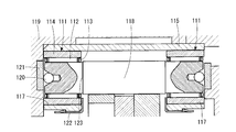
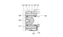
- the needle roller bearing 111 includes a needle roller 112, a cage 113, and an outer ring 114 as shown in FIG.
- the needle roller bearing 111 is interposed between both ends of the outer pin 118 and the hole 117 of the outer pin housing 115 that supports the outer pin 118.
- the outer pin housing 115 is fitted and fixed to the inner surface of the reduction gear housing 119.
- the needle roller bearing 111 reduces the friction in the radial direction of the outer pin 118, and a steel ball 120 is interposed between the end surface of the outer pin 118 and the speed reducer housing 119. Friction can be reduced.
- a thrust plate 121 may be embedded in the contact surface of the steel ball 120. Further, the flange portion of the clip 122 engaged with the outer pin housing 115 is engaged with the inner end surface of the outer ring 114, so that the outer ring 114 is prevented from coming off.
- the cage 113 of the needle roller bearing 111 is prevented from moving by the wall of the speed reducer housing 119 to the outside in the axial direction, but is obstructed to the inside in the opposite direction. Therefore, the cage 113 may come out together with the needle rollers 112 when subjected to vibration, impact, or the like.
- the provision of the stepped portion 123 on the outer pin 118 increases the manufacturing process and increases the inspection time for managing the outer diameter, which increases the cost.
- the present invention is accompanied by an increase in cost and an increase in the size of the housing in the cycloid speed reducer and the in-wheel motor drive device using the same, which prevents the retainer of the needle roller bearing that supports the outer pin from coming out. It is a problem to realize without.
- the present invention includes an eccentric cam provided on an input shaft, a curved plate that is rotatably fitted to an outer peripheral surface of the eccentric cam and has an arc gear on the outer peripheral portion, and the arc gear.
- the retainer of the needle roller bearing is provided with an engaging portion, and the engaging portion is engaged in the axial direction with a fixing member that is radially adjacent to the retainer and fixed in the axial direction.
- the “engagement portion” of the cage specifically refers to an engagement collar portion formed by bending the outer edge of the cage toward the inner diameter side or the outer diameter side.
- the “fixing member radially adjacent to the cage and fixed in the axial direction” specifically refers to an outer pin or an outer ring.
- the engaging portion is provided in the cage of the needle roller bearing that supports the outer pin, and the engaging portion is used as a fixing member.
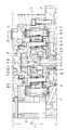
- FIG. 1 is a cross-sectional view of an in-wheel motor drive device.
- FIG. 2 is an enlarged cross-sectional view of the deceleration portion same as above.
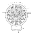
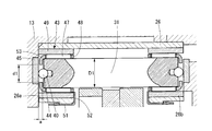
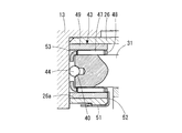
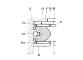
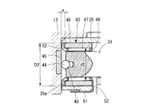
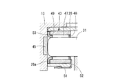
- 3 is a cross-sectional view taken along line X1-X1 of FIG. 4 is an enlarged cross-sectional view of the outer pin support portion of FIG. 5 is a partially enlarged cross-sectional view of another example 1 of the outer pin support portion of FIG. 6 is a partially enlarged cross-sectional view of another example 2 of the outer pin support portion of FIG. 7 is a partially enlarged cross-sectional view of another example 3 of the outer pin support portion of FIG. 8 is a partially enlarged cross-sectional view of another example 4 of the outer pin support portion of FIG.
- FIG. 9 is an enlarged cross-sectional view of a conventional outer pin support portion.
- FIG. 10 is a partially enlarged cross-sectional view of another example of a conventional outer pin support portion.
- the in-wheel motor drive device 11 includes a motor unit A that generates a driving force, a deceleration unit B that decelerates and outputs the rotation of the motor unit A, and a deceleration unit.
- a wheel hub bearing portion C that transmits the output of the portion B to the wheels is provided.
- the motor part A is incorporated in the motor housing 12, and the reduction part B is incorporated in the reduction part housing 13.
- a speed reduction unit housing 13 is connected and fixed to the front end of the motor housing 12 by a bolt 14.
- the motor part A includes a stator 15 fixed to the motor housing 12 and a rotor 17 integrated with the motor shaft 16, and the stator 15 and the rotor 17 constitute a radial gap motor opposed to each other in the radial direction.
- the rotor 17 is fixed to the flange 19 of the motor shaft 16 by bolts 18.
- the motor shaft 16 is rotatably supported by the motor housing 12 via rolling bearings 21a and 21b at both front and rear ends.
- the motor shaft 16 is provided with an internal passage 22, and the input shaft 23 of the speed reduction portion B is connected to the front end of the internal passage 22.
- the input shaft 23 is also provided with an internal passage 25, and both the internal passages 22 and 25 communicate with each other.
- the reduction part B is comprised by the cycloid reduction gear which is the object of this invention.
- the speed reduction part B includes an annular outer pin housing 26 fitted and fixed concentrically with the input shaft 23 on the inner diameter surface of the speed reduction part housing 13 (see FIGS. 1 and 2), and each member constituting the speed reduction part B Is provided on the inner diameter side of the outer pin housing 26.
- a pair of eccentric cams 27a and 27b provided adjacent to each other in the axial direction on the input shaft 23, and the eccentric cams 27a and 27b via cylindrical roller bearings 28a and 28b.
- Rotating curved plates 29a and 29b, a plurality of outer pins 31 (see FIG. 3) fixed at equal intervals along the inner diameter surface of the outer pin housing 26, and the rotational motion of the curved plates 29a and 29b are output members.
- There is a motion conversion mechanism 20 constituted by an inner pin 34 that transmits to 32 and its through hole 39, counterweights 33a, 33b attached to the input shaft 23 adjacent to the outer side in the axial direction of the eccentric cams 27a, 27b, etc. .
- the eccentric cams 27a and 27b are provided with a 180 ° phase change so as to cancel out centrifugal forces due to the eccentric motion.
- the output member 32 has a flange portion 32a and a shaft portion 32b (see FIG. 2).
- One end portions of a plurality of inner pins 34 are inserted into and fixed to the flange portion 32a at equal intervals on the circumference around the rotation axis of the output member 32.
- the shaft portion 32b is fitted and fixed to the inner diameter surface of the wheel hub 35, and transmits the output of the speed reduction portion B to the wheel.
- a rolling bearing 36 is interposed between the inner diameter surface of the flange portion 32a of the output member 32 and the input shaft 23, so that the input shaft 23 and the output member 32 are held concentrically and are relatively rotatable.
- the other end portion of the inner pin 34 is inserted and supported by a flange portion 37a of the stabilizer 37 (see FIG. 2).
- the stabilizer 37 has a cylindrical portion 37b provided on the inner diameter of the flange portion 37a, and the cylindrical portion 37b has a front end portion (end portion on the speed reduction portion B side) outer diameter of the motor shaft 16 through a needle roller bearing 38.
- the surface is rotatably fitted.
- the curved plates 29a and 29b have an arc gear 30 formed of a trochoidal curve such as epitrochoid on the outer peripheral portion, and a plurality of penetrating holes penetrating from one end surface to the other end surface in the axial direction.
- a hole 39 is provided.
- the through holes 39 are provided in the same number and at the same intervals as the inner pins 34 on the circumference around the rotation axis of the curved plates 29a and 29b, and the inner pins 34 are provided in the respective through holes 39. It is inserted with a margin in the radial direction (twice the amount of eccentricity).
- the curved plates 29a and 29b are rotatably supported by the eccentric cams 27a and 27b via cylindrical roller bearings 28a and 28b, respectively.
- the phases of the curved plates 29a and 29b are also shifted by 180 ° in the same direction as the eccentric cams 27a and 27b.
- counterweights 33a and 33b are provided adjacent to the outer sides in the axial direction of the eccentric cams 27a and 27b. These counterweights 33a and 33b are attached to the eccentric cams 27a and 27b in an eccentric state in which the phase is changed by 180 °.
- the outer pin housing 26 is formed in an annular shape (see FIG. 3), and is provided with holes 26a, 26b corresponding to the number of outer pins 31, respectively, at regular intervals in the circumferential direction. Both end portions of the outer pin 31 are inserted into the holes 26 a and 26 b and supported by the speed reduction unit housing 13 through the needle roller bearings 43.
- the number of the outer pins 31 is one more than the number of teeth of the arcuate gears 30 of the curved plates 29a and 29b, and a plurality of outer pins 31 are simultaneously engaged with the arcuate gears 30.
- the above-described motion conversion mechanism 20 includes a plurality of inner pins 34 fixed to the output member 32 and through holes 39 provided in the curved plates 29a and 29b.
- the inner diameter dimension of the through-hole 39 is only twice the eccentric amount of the eccentric cams 27a and 27b from the outer diameter dimension of the inner pin 34 (referred to as "the maximum outer diameter including the needle roller bearings 46a and 46b"). It is set large.
- the inner pin 34 partially contacts the inner wall surface of the through hole 39 as the curved plates 29a and 29b rotate. As a result, the revolving motion of the curved plates 29 a and 29 b is not transmitted to the inner pin 34, but the motion converted into only the rotational motion is transmitted to the inner pin 34.
- the inner pins 34 are provided at equal intervals on a circumferential track centering on the rotational axis of the output member 32. As described above, one end of the inner pin 34 is fixed to the output member 32, and the other end. Is fixed to the stabilizer 37. In order to reduce the frictional resistance with the curved plates 29a, 29b, needle roller bearings 46a, 46b are provided in portions of the curved plates 29a, 29b that pass through the through holes 39, and each inner pin 34 has its needle roller bearing. It partially contacts the through hole 39 via 46a and 46b.
- the needle roller bearing 43 that rotatably supports the outer pin 31 is a combination of a needle roller 47, its retainer 48, and an outer ring 49.
- the holes 26a and 26b are fitted.
- the flange 52 of the clip 51 engaged with the outer pin housing 26 is engaged with the inner end surface of the outer ring 49. By the engagement, the outer ring 49 is prevented from moving in the axial direction with respect to the outer pin housing 26 and is fixed.
- pockets 40 are provided at both ends of the outer pin 31, and the steel balls 44 held in the pockets 40 are abutted against the inner surface of the speed reduction unit housing 13. Thereby, the friction in the thrust direction of the outer pin 31 is reduced.
- a thrust plate 45 is embedded in the inner surface of the speed reduction unit housing 13 that is in contact with the steel ball 44. The steel ball 44 may be brought into direct contact with the inner surface of the speed reduction unit housing 13 (see FIG. 5).
- the outer edge of the retainer 48 (the side edge on the outer end side of the outer pin 31) is formed with a larger width in the axial direction than usual, and a portion that does not impair the original function of the retainer is bent toward the inner diameter side.
- the engagement flange 53 is formed.
- the engagement flange 53 is interposed in a gap a between the end surface of the outer pin 31 and the inner surface of the speed reduction unit housing 13 facing the outer pin 31, and is adjacent to the outer pin 31 (that is, the inner diameter side of the cage 48).
- the outer end surface of the fixing member is engaged in the axial direction.
- the gap a is formed to be slightly larger than the thickness of the engagement flange portion 53 so that the engagement flange portion 53 can rotate relative to the outer pins 31 and the speed reduction portion housing 13 on both sides thereof. Further, the outer end portion of the outer ring 49 is formed longer than usual so that it can abut against the inner surface of the speed reduction unit housing 13 so that the outer ring 49 can be easily positioned in the axial direction.
- the needle roller bearing 43 is constituted by the needle roller 47 and its retainer 48, and there is no outer ring 49 as described above.
- the inner diameter surfaces of the holes 26 a and 26 b of the outer pin housing 26 become rolling surfaces of the needle rollers 47.
- the engaging flange 53 bent to the inner diameter side is formed at the outer edge of the cage 48 and is engaged with the outer end surface of the outer pin 31 in the axial direction as in the case described above.
- the engagement flange 53 is formed by bending the outer edge of the cage 48 in the outer diameter direction.
- the engagement flange 53 is interposed in a portion of a gap a between the outer ring 49 and the speed reduction unit housing 13, and engages with the outer ring 49 which is a fixing member adjacent to the outer diameter side of the cage 48 in the axial direction. Is done.
- Other configurations are the same as those in FIGS. 5 and 6.
- the engagement flange 53 is bent in the outer diameter direction as in the case of FIG. 7, but the outer end surface of the outer pin 31 is formed into a spherical surface or an arc surface. The surface is directly pressed against the inner surface of the speed reduction unit housing 13.
- the retainer 48 may be either a resin manufactured by injection molding or cutting, or a metal manufactured by pressing or welding. In the case of a pressed metal cage, surface modification such as plating for improving the coefficient of friction and improving wear resistance may be performed on the surface.
- a rotary pump 55 As a mechanism for supplying lubricating oil to the speed reduction portion B, a rotary pump 55 (see FIGS. 1 and 2) is provided on the outer diameter surface of the cylindrical portion 37b of the stabilizer 37 in the inner diameter portion of the wall surface of the motor housing 12 on the speed reduction portion B side.
- An oil supply passage 56 that is provided and reaches the inside of the speed reduction portion B and a return passage 57 that finishes lubrication and returns from the speed reduction portion B are provided.
- the oil supply passage 56 reaches the rear end of the motor shaft 16 along the inner side of the motor housing 12, and corresponds to the internal passages 22 and 25 of the motor shaft 16 and the input shaft 23 and the eccentric cams 27a and 27b of the input shaft 23.
- the oil supply holes 58a and 58b (see FIG. 2) provided in the radial direction at the position are reached, and the lubricating oil is supplied into the speed reduction unit B through this path.
- the returned lubricating oil returns to the rotary pump via the return passage 57 from the lubricating oil reservoir 59 provided on the outer bottom of the speed reduction unit housing 13.
- the wheel hub bearing portion C includes a wheel hub 35 fixedly connected to the output member 32 of the speed reduction portion B, and a wheel hub bearing 60 that rotatably holds the wheel hub 35 with respect to the speed reduction portion housing 13.
- the output member 32 is inserted into the inner diameter surface of the wheel hub 35 and splined, and the tip of the output member 32 exposed from the wheel hub 35 is fastened with a nut 50 to connect the output member 32 and the wheel hub 35. ing.
- the motor unit A receives an electromagnetic force generated by supplying an alternating current to the coil of the stator 15, and the rotor 17 constituted by a permanent magnet or a magnetic material rotates.
- the eccentric cams 27a and 27b perform eccentric rotational movement, so that the curved plates 29a and 29b become the rotational axis of the input shaft 23.
- the revolving motion is performed at the speed of the input shaft 23 around the center.
- the plurality of outer pins 31 engage with the arcuate gears 30 of the curved plates 29a and 29b to cause the curved plates 29a and 29b to rotate at a low speed in the direction opposite to the rotation direction of the input shaft 23. .
- the inner pin 34 inserted through the through-hole 39 partially contacts the inner wall surface of the through-hole 39 as the curved plates 29a and 29b rotate.
- the revolving motion of the curved plates 29a, 29b is not transmitted to the inner pin 34, but is converted into only the rotational motion of the curved plates 29a, 29b. It is transmitted to the bearing portion C.
- the reduction ratio of the reduction part B having the above-described configuration is calculated as (ZA ⁇ ZB) / ZB, where ZA is the number of outer pins 31 and ZB is the number of arc gears 30 of the curved plates 29a and 29b.
- the in-wheel motor drive device 11 having a compact and high reduction ratio can be obtained.
- the outer pin 31 is supported by the needle roller bearing 43 and the needle roller bearings 46a and 46b are provided at positions where they contact the curved plates 29a and 29b of the inner pin 34, the frictional resistance is reduced.
- the transmission efficiency of the deceleration part B is improved.
- the retainer 48 of the needle roller bearing 43 that supports the outer pin 31 has an engagement flange portion 53 provided on the outer end edge thereof in the radial direction with respect to the outer pin 31 or the outer ring 49 (that is, the retainer 48 in the radial direction).
Landscapes
- Engineering & Computer Science (AREA)
- Mechanical Engineering (AREA)
- Chemical & Material Sciences (AREA)
- Combustion & Propulsion (AREA)
- Transportation (AREA)
- General Engineering & Computer Science (AREA)
- Retarders (AREA)
- Arrangement Or Mounting Of Propulsion Units For Vehicles (AREA)
Abstract
La présente invention porte sur une configuration d'un décélérateur cycloïde et sur un dispositif d'entraînement de moteur dans la roue utilisant celui-ci dans lesquels un élément de retenue d'un roulement à aiguilles qui supporte une broche externe est empêché de sortir, sans augmentation du coût ou de la dimension du boîtier. Dans le décélérateur cycloïde, une section de bride d'engagement (53) qui est incurvée radialement vers l'intérieur est disposée sur le bord externe de l'élément de retenue (48) d'un roulement à aiguilles (43) qui supporte une broche externe (31), et cette section de bride d'engagement (53) vient en prise dans la direction axiale avec la face d'extrémité externe de la broche externe (31) de façon à empêcher l'élément de retenue (48) de sortir.
Applications Claiming Priority (2)
| Application Number | Priority Date | Filing Date | Title |
|---|---|---|---|
| JP2011066347A JP2012202457A (ja) | 2011-03-24 | 2011-03-24 | サイクロイド減速機及びインホイールモータ駆動装置 |
| JP2011-066347 | 2011-03-24 |
Publications (1)
| Publication Number | Publication Date |
|---|---|
| WO2012128003A1 true WO2012128003A1 (fr) | 2012-09-27 |
Family
ID=46879161
Family Applications (1)
| Application Number | Title | Priority Date | Filing Date |
|---|---|---|---|
| PCT/JP2012/055034 Ceased WO2012128003A1 (fr) | 2011-03-24 | 2012-02-29 | Décélérateur cycloïde et dispositif d'entraînement de moteur dans la roue |
Country Status (2)
| Country | Link |
|---|---|
| JP (1) | JP2012202457A (fr) |
| WO (1) | WO2012128003A1 (fr) |
Cited By (8)
| Publication number | Priority date | Publication date | Assignee | Title |
|---|---|---|---|---|
| EP3232083A1 (fr) * | 2016-04-13 | 2017-10-18 | TERAFORCE Precision Technology Co., Ltd. | Dispositif de changement de vitesse |
| EP3318128A3 (fr) * | 2012-05-30 | 2018-06-27 | Bayer CropScience Aktiengesellschaft | Compositions comprenant un agent de contrôle biologique et un fongicide |
| WO2018147200A1 (fr) * | 2017-02-10 | 2018-08-16 | 住友重機械工業株式会社 | Dispositif formant train épicycloïdal |
| CN110234906A (zh) * | 2017-03-15 | 2019-09-13 | 株式会社日精 | 差动减速器 |
| CN112145630A (zh) * | 2020-09-26 | 2020-12-29 | 南京好龙电子有限公司 | 具有行星架定位机构的行星齿轮减速器 |
| WO2021104970A1 (fr) * | 2019-11-29 | 2021-06-03 | Magna powertrain gmbh & co kg | Boîtier pour machine électrique et machine électrique le comprenant |
| US20220316560A1 (en) * | 2021-03-31 | 2022-10-06 | Mikuni Corporation | Rotation driving device |
| CN115388134A (zh) * | 2022-09-02 | 2022-11-25 | 苏州觅径智能科技有限公司 | 一种摆线减速器 |
Families Citing this family (8)
| Publication number | Priority date | Publication date | Assignee | Title |
|---|---|---|---|---|
| JP2015121272A (ja) * | 2013-12-24 | 2015-07-02 | Ntn株式会社 | インホイールモータ駆動装置 |
| JP2015121270A (ja) * | 2013-12-24 | 2015-07-02 | Ntn株式会社 | インホイールモータ駆動装置 |
| JP6400297B2 (ja) * | 2014-01-29 | 2018-10-03 | Ntn株式会社 | インホイールモータ駆動装置 |
| WO2015104980A1 (fr) * | 2014-01-08 | 2015-07-16 | Ntn株式会社 | Dispositif d'entraînement de moteur-roue |
| JP2015129570A (ja) * | 2014-01-09 | 2015-07-16 | Ntn株式会社 | 電気自動車用駆動装置 |
| JP2015175512A (ja) * | 2014-03-18 | 2015-10-05 | Ntn株式会社 | インホイールモータ駆動装置 |
| CN105570437B (zh) * | 2016-03-12 | 2019-02-15 | 深圳市领略数控设备有限公司 | 一种低背隙机器人减速机 |
| JP2018173173A (ja) * | 2018-06-15 | 2018-11-08 | Ntn株式会社 | インホイールモータ駆動装置 |
Citations (4)
| Publication number | Priority date | Publication date | Assignee | Title |
|---|---|---|---|---|
| JPH11173386A (ja) * | 1997-12-11 | 1999-06-29 | Teijin Seiki Co Ltd | 遊星歯車装置 |
| JP2006177511A (ja) * | 2004-12-24 | 2006-07-06 | Jtekt Corp | 軸受装置 |
| JP2008038941A (ja) * | 2006-08-02 | 2008-02-21 | Sumitomo Heavy Ind Ltd | 偏心揺動歯車装置 |
| JP2010048280A (ja) * | 2008-08-19 | 2010-03-04 | Ntn Corp | インホイールモータ駆動装置 |
-
2011
- 2011-03-24 JP JP2011066347A patent/JP2012202457A/ja not_active Withdrawn
-
2012
- 2012-02-29 WO PCT/JP2012/055034 patent/WO2012128003A1/fr not_active Ceased
Patent Citations (4)
| Publication number | Priority date | Publication date | Assignee | Title |
|---|---|---|---|---|
| JPH11173386A (ja) * | 1997-12-11 | 1999-06-29 | Teijin Seiki Co Ltd | 遊星歯車装置 |
| JP2006177511A (ja) * | 2004-12-24 | 2006-07-06 | Jtekt Corp | 軸受装置 |
| JP2008038941A (ja) * | 2006-08-02 | 2008-02-21 | Sumitomo Heavy Ind Ltd | 偏心揺動歯車装置 |
| JP2010048280A (ja) * | 2008-08-19 | 2010-03-04 | Ntn Corp | インホイールモータ駆動装置 |
Cited By (14)
| Publication number | Priority date | Publication date | Assignee | Title |
|---|---|---|---|---|
| EP3318128A3 (fr) * | 2012-05-30 | 2018-06-27 | Bayer CropScience Aktiengesellschaft | Compositions comprenant un agent de contrôle biologique et un fongicide |
| EP3232083A1 (fr) * | 2016-04-13 | 2017-10-18 | TERAFORCE Precision Technology Co., Ltd. | Dispositif de changement de vitesse |
| WO2018147200A1 (fr) * | 2017-02-10 | 2018-08-16 | 住友重機械工業株式会社 | Dispositif formant train épicycloïdal |
| JP2018128115A (ja) * | 2017-02-10 | 2018-08-16 | 住友重機械工業株式会社 | 遊星歯車装置 |
| CN110234905A (zh) * | 2017-02-10 | 2019-09-13 | 住友重机械工业株式会社 | 行星齿轮装置 |
| US11078991B2 (en) | 2017-02-10 | 2021-08-03 | Sumitomo Heavy Industries, Ltd. | Planetary gear device |
| CN110234906B (zh) * | 2017-03-15 | 2023-03-07 | 株式会社日精 | 差动减速器 |
| CN110234906A (zh) * | 2017-03-15 | 2019-09-13 | 株式会社日精 | 差动减速器 |
| WO2021104970A1 (fr) * | 2019-11-29 | 2021-06-03 | Magna powertrain gmbh & co kg | Boîtier pour machine électrique et machine électrique le comprenant |
| US12155289B2 (en) | 2019-11-29 | 2024-11-26 | Magna Powertrain Gmbh & Co. Kg | Housing for an electric machine and electric machine comprising such a housing |
| CN112145630A (zh) * | 2020-09-26 | 2020-12-29 | 南京好龙电子有限公司 | 具有行星架定位机构的行星齿轮减速器 |
| US11624424B2 (en) * | 2021-03-31 | 2023-04-11 | Mikuni Corporation | Rotation driving device |
| US20220316560A1 (en) * | 2021-03-31 | 2022-10-06 | Mikuni Corporation | Rotation driving device |
| CN115388134A (zh) * | 2022-09-02 | 2022-11-25 | 苏州觅径智能科技有限公司 | 一种摆线减速器 |
Also Published As
| Publication number | Publication date |
|---|---|
| JP2012202457A (ja) | 2012-10-22 |
Similar Documents
| Publication | Publication Date | Title |
|---|---|---|
| WO2012128003A1 (fr) | Décélérateur cycloïde et dispositif d'entraînement de moteur dans la roue | |
| JP5374215B2 (ja) | サイクロイド減速機、インホイールモータ駆動装置、および車両用モータ駆動装置 | |
| KR101266266B1 (ko) | 감속장치 | |
| JP5709373B2 (ja) | インホイールモータ駆動装置 | |
| JP5297758B2 (ja) | インホイールモータ駆動装置 | |
| CN105848951A (zh) | 轮内电动机驱动装置 | |
| US20160167505A1 (en) | In-wheel motor drive device | |
| CN104675934A (zh) | 电动车辆变速驱动桥 | |
| JP5430517B2 (ja) | 車両の駆動装置 | |
| JP2015092098A (ja) | インホイールモータ駆動装置 | |
| JP2008309264A (ja) | サイクロイド減速機およびインホイールモータ駆動装置 | |
| JP2008184017A (ja) | インホイールモータ駆動装置 | |
| JP2016038086A (ja) | 車輪駆動装置 | |
| JP6324761B2 (ja) | インホイールモータ駆動装置 | |
| WO2016017351A1 (fr) | Réducteur de vitesse cycloïdal et dispositif d'entraînement de moteur dans roue pourvu de ce réducteur | |
| JP2008261445A (ja) | インホイールモータ駆動装置 | |
| WO2015133278A1 (fr) | Dispositif d'entraînement de moteur-roue | |
| JP5762719B2 (ja) | インホイールモータ駆動装置 | |
| JP2023144282A (ja) | ギアモータ | |
| WO2015137073A1 (fr) | Dispositif d'entrainement de moteur-roue | |
| WO2021182019A1 (fr) | Actionneur électrique | |
| JP2017019389A (ja) | 車両用モータ駆動装置 | |
| JP2009190659A (ja) | 鉄道車両駆動ユニット | |
| JP2012167684A (ja) | 軸受構造 | |
| JP5830133B2 (ja) | インホイールモータ駆動装置 |
Legal Events
| Date | Code | Title | Description |
|---|---|---|---|
| 121 | Ep: the epo has been informed by wipo that ep was designated in this application |
Ref document number: 12761320 Country of ref document: EP Kind code of ref document: A1 |
|
| NENP | Non-entry into the national phase |
Ref country code: DE |
|
| 122 | Ep: pct application non-entry in european phase |
Ref document number: 12761320 Country of ref document: EP Kind code of ref document: A1 |