WO2012128075A1 - Dispositif d'ouverture/de fermeture électromagnétique - Google Patents
Dispositif d'ouverture/de fermeture électromagnétique Download PDFInfo
- Publication number
- WO2012128075A1 WO2012128075A1 PCT/JP2012/056101 JP2012056101W WO2012128075A1 WO 2012128075 A1 WO2012128075 A1 WO 2012128075A1 JP 2012056101 W JP2012056101 W JP 2012056101W WO 2012128075 A1 WO2012128075 A1 WO 2012128075A1
- Authority
- WO
- WIPO (PCT)
- Prior art keywords
- contact
- switching device
- electromagnetic switching
- movable
- closing
- Prior art date
- Legal status (The legal status is an assumption and is not a legal conclusion. Google has not performed a legal analysis and makes no representation as to the accuracy of the status listed.)
- Ceased
Links
Images





Classifications
-
- G—PHYSICS
- G01—MEASURING; TESTING
- G01R—MEASURING ELECTRIC VARIABLES; MEASURING MAGNETIC VARIABLES
- G01R31/00—Arrangements for testing electric properties; Arrangements for locating electric faults; Arrangements for electrical testing characterised by what is being tested not provided for elsewhere
- G01R31/327—Testing of circuit interrupters, switches or circuit-breakers
-
- H—ELECTRICITY
- H01—ELECTRIC ELEMENTS
- H01H—ELECTRIC SWITCHES; RELAYS; SELECTORS; EMERGENCY PROTECTIVE DEVICES
- H01H1/00—Contacts
- H01H1/0015—Means for testing or for inspecting contacts, e.g. wear indicator
-
- G—PHYSICS
- G01—MEASURING; TESTING
- G01R—MEASURING ELECTRIC VARIABLES; MEASURING MAGNETIC VARIABLES
- G01R31/00—Arrangements for testing electric properties; Arrangements for locating electric faults; Arrangements for electrical testing characterised by what is being tested not provided for elsewhere
- G01R31/327—Testing of circuit interrupters, switches or circuit-breakers
- G01R31/3277—Testing of circuit interrupters, switches or circuit-breakers of low voltage devices, e.g. domestic or industrial devices, such as motor protections, relays, rotation switches
- G01R31/3278—Testing of circuit interrupters, switches or circuit-breakers of low voltage devices, e.g. domestic or industrial devices, such as motor protections, relays, rotation switches of relays, solenoids or reed switches
-
- H—ELECTRICITY
- H01—ELECTRIC ELEMENTS
- H01H—ELECTRIC SWITCHES; RELAYS; SELECTORS; EMERGENCY PROTECTIVE DEVICES
- H01H47/00—Circuit arrangements not adapted to a particular application of the relay and designed to obtain desired operating characteristics or to provide energising current
- H01H47/002—Monitoring or fail-safe circuits
-
- H—ELECTRICITY
- H01—ELECTRIC ELEMENTS
- H01H—ELECTRIC SWITCHES; RELAYS; SELECTORS; EMERGENCY PROTECTIVE DEVICES
- H01H50/00—Details of electromagnetic relays
- H01H50/54—Contact arrangements
-
- H—ELECTRICITY
- H01—ELECTRIC ELEMENTS
- H01H—ELECTRIC SWITCHES; RELAYS; SELECTORS; EMERGENCY PROTECTIVE DEVICES
- H01H50/00—Details of electromagnetic relays
- H01H50/54—Contact arrangements
- H01H50/541—Auxiliary contact devices
-
- H—ELECTRICITY
- H01—ELECTRIC ELEMENTS
- H01H—ELECTRIC SWITCHES; RELAYS; SELECTORS; EMERGENCY PROTECTIVE DEVICES
- H01H71/00—Details of the protective switches or relays covered by groups H01H73/00 - H01H83/00
- H01H71/04—Means for indicating condition of the switching device
-
- H—ELECTRICITY
- H01—ELECTRIC ELEMENTS
- H01H—ELECTRIC SWITCHES; RELAYS; SELECTORS; EMERGENCY PROTECTIVE DEVICES
- H01H71/00—Details of the protective switches or relays covered by groups H01H73/00 - H01H83/00
- H01H71/04—Means for indicating condition of the switching device
- H01H2071/044—Monitoring, detection or measuring systems to establish the end of life of the switching device, can also contain other on-line monitoring systems, e.g. for detecting mechanical failures
-
- H—ELECTRICITY
- H01—ELECTRIC ELEMENTS
- H01H—ELECTRIC SWITCHES; RELAYS; SELECTORS; EMERGENCY PROTECTIVE DEVICES
- H01H36/00—Switches actuated by change of magnetic field or of electric field, e.g. by change of relative position of magnet and switch, by shielding
- H01H36/0006—Permanent magnet actuating reed switches
- H01H36/0046—Limit switches, also fail-safe operation or anti-tamper considerations
-
- H—ELECTRICITY
- H01—ELECTRIC ELEMENTS
- H01H—ELECTRIC SWITCHES; RELAYS; SELECTORS; EMERGENCY PROTECTIVE DEVICES
- H01H50/00—Details of electromagnetic relays
- H01H50/54—Contact arrangements
- H01H50/541—Auxiliary contact devices
- H01H50/545—Self-contained, easily replaceable microswitches
-
- H—ELECTRICITY
- H01—ELECTRIC ELEMENTS
- H01H—ELECTRIC SWITCHES; RELAYS; SELECTORS; EMERGENCY PROTECTIVE DEVICES
- H01H9/00—Details of switching devices, not covered by groups H01H1/00 - H01H7/00
- H01H9/0066—Auxiliary contact devices
Definitions
- the present invention relates to an electromagnetic switching device such as an electromagnetic relay.
- Patent Document 1 As a conventional electromagnetic switching device, for example, there is one described in Patent Document 1.
- a relay unit (electromagnetic relay) is housed in a synthetic resin case, and is connected to a pair of main terminals connected to the contact of the relay unit and an electromagnet coil of the relay unit. And a pair of coil terminals projecting from the case.
- the pair of main terminals are connected to the power supply path from the power source to the load, and when the excitation current flows between the pair of coil terminals, the relay unit (electromagnetic switching device) is turned on, and the excitation current is between the coil terminals.
- the relay unit electromagagnetic switchgear
- the life is mainly set according to the number of operations of the relay unit (contact switching frequency), and it is considered that the failure rate rapidly increases after the life. Therefore, in order to use the electromagnetic switchgear safely and appropriately, it is important to manage the life of the electromagnetic switchgear.
- the present invention has been made in view of the above problems, and has an object to make life management easier than before.
- the electromagnetic switching device of the present invention is an electromagnetic switching device that opens and closes a contact in response to a command from the outside, and is based on a measuring unit that measures a change associated with the opening and closing of the contact and the change measured by the measuring unit. And determining means for determining the state of the contact and output means for outputting the determination result of the determining means to the outside.
- the measuring means measures the number of times the contact is opened and closed.
- the measuring means measures the number of times of opening and closing based on the number of times of input of the command.
- an auxiliary contact interlocking with the opening and closing of the contact is provided, and the measuring means measures the number of times the contact is opened and closed based on the number of times the auxiliary contact is opened and closed.
- the contact includes a fixed contact and a movable contact, and includes an electromagnet that contacts and separates the movable contact with the fixed contact using electromagnetic force, and the measuring means includes a coil that constitutes the electromagnet. It is preferable to measure the number of times the contact is opened and closed based on a change in impedance.
- the contact includes a fixed contact and a movable contact, and includes a displacement means for displacing the movable contact, and the measuring means opens and closes the contact based on the displacement of the movable contact by the displacement means. It is preferable to measure the number of times.
- the contact includes a fixed contact and a movable contact, and includes a displacement means for displacing the movable contact by applying an external force, and the measuring means is based on a distortion caused by the external force applied by the displacement means. It is preferable to measure the number of times the contact is opened and closed.
- the measuring means measures the number of times the contact is opened and closed based on a voltage applied to the contact.
- the determination means determines the state of the contact based on the number of times the contact is opened and closed per predetermined time.
- the measuring means measures an accumulated time during which the contact is closed.
- the electromagnetic switchgear of the present invention has an effect that the life can be easily managed as compared with the conventional one.
- (A), (b) is a block diagram which shows Embodiment 1 of this invention.
- (A), (b) is sectional drawing abbreviate
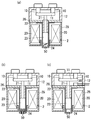
- (A)-(c) is sectional drawing which abbreviate
- (A), (b) is sectional drawing which abbreviate
- (A)-(c) is sectional drawing which abbreviate
- Embodiment 6 of this invention is shown, (a) is a block diagram, (b) is operation
- Embodiment 7 of this invention is shown, (a) is a block diagram, (b) is operation
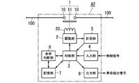
- the electromagnetic switching device A1 of the present embodiment includes a contact portion 1, a drive portion 2, a control portion 3, an input portion 4, a measurement portion 5, a life determination portion 6, a storage portion 7, and an output portion. 8 etc.
- the contact portion 1 has two fixed contacts 10 inserted in the middle of the electric circuit 100 and a movable contact (movable element) 11 that contacts and separates from the fixed contact 10. That is, when the two fixed contacts 10 and the movable contact 11 are in contact, the contact portion 1 is closed and the electric circuit 100 is conducted, and when the two fixed contacts 10 and the movable contact 11 are not in contact, the contact portion. 1 opens and the electric circuit 100 becomes non-conductive.
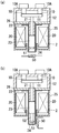
- FIG. 2A shows a cross-sectional view in which the electromagnetic switching device A1 of the present embodiment is partially omitted.
- the vertical and horizontal directions are defined in FIG.
- the fixed contact 10 is provided at the tip (lower end) of a cylindrical fixed terminal 10A.
- the movable contact 11 is formed in a rectangular flat plate shape made of copper or a copper alloy, and is supported by the movable shaft 21 at the center in the longitudinal direction (left-right direction).
- the fixed contact 10 and the movable contact 11 are housed in a ceramic sealing container 12 formed in a box shape with an open bottom surface, and a pair of fixed terminals 10A penetrates the bottom wall of the sealing container 12. is doing.
- the drive unit 2 includes an exciting coil 20, a movable shaft 21, a fixed iron core 22, a movable iron core 23, a cap 24, yokes 25 and 26, and the like.
- the cap 24 is formed of a nonmagnetic material in a bottomed cylindrical shape, and the movable iron core 23 is accommodated on the bottom (lower) side of the inside, and the fixed iron core 22 is accommodated and fixed on the opening (upper) side.
- the movable shaft 21 movably passes through the fixed iron core 22 and has a movable iron core 23 fixed to the lower end portion.
- a return spring is provided between the fixed iron core 22 and the movable iron core 23 to elastically urge the movable iron core 23 in a direction away from the fixed iron core 22 (downward).
- a contact pressure spring (not shown) that elastically biases the movable contact 11 in a direction (upward) toward the fixed contact 10 is disposed between the fixed iron core 22 and the movable contact 11.
- a coil bobbin (not shown) made of an insulating material is provided outside the cap 24, and the exciting coil 20 is wound around the coil bobbin.
- the yokes 25 and 26 are disposed outside the exciting coil 20, and a magnetic circuit is formed by the exciting coil 20 and the yokes 25 and 26.
- One yoke 26 is formed in a flat plate shape and is disposed between the exciting coil 20 and the sealing container 12.
- the movable shaft 21 and the movable contact 11 are also displaced downward by the movable iron core 23 elastically biased by the return spring being displaced (moved) downward.
- the movable contact 11 is separated from the fixed contact 10 and the contact portion 1 is opened.
- the exciting coil 20 and the fixed iron core 22 constitute an electromagnet
- the movable iron core 23 is displaced by the electromagnetic force of the electromagnet.
- the control unit 3 controls the drive unit 2 according to a control signal input to the input unit 4 from the outside. That is, when a contact ON control signal is input to the input unit 4, the control unit 3 applies an excitation current to the excitation coil 20 of the drive unit 2 to close the contact unit 1, and controls the input unit 4 to turn off the contact. When the signal is input, the control unit 3 stops the excitation current flowing through the excitation coil 20 and opens the contact unit 1.
- the control signal is a DC voltage signal that switches between a high level and a low level, with the high level corresponding to contact ON and the low level corresponding to contact OFF.
- the measuring unit 5 measures the number of opening / closing of the contact unit 1 as a change accompanying the opening / closing of the contact, and measures the number of opening / closing of the contact unit 1 based on the number of opening / closing of the auxiliary contact 50. Note that the number of times of opening and closing the contact portion 1 is stored in the storage portion 7, and the number of times of opening and closing stored in the storage portion 7 is counted up by the measuring portion 5 every time the contact portion 1 is opened and closed.
- the auxiliary contact 50 is composed of a reed switch arranged below the cap 24 as shown in FIG. 2A, and is turned on by the magnetic force of the permanent magnet 51 attached to the lower surface of the movable core 23. That is, when the contact portion 1 is open, the reed switch (auxiliary contact 50) is turned on by the magnetic force of the permanent magnet 51 because the movable iron core 23 is positioned on the bottom (lower) side of the cap 24. However, when the contact portion 1 is closed, the movable iron core 23 is positioned on the opening (upper) side of the cap 24, so that the magnetic force of the permanent magnet 51 becomes difficult and the reed switch (auxiliary contact 50) is turned off. It becomes.
- the auxiliary contact 50 may be disposed on the side surface of the cap 24 as shown in FIG. In this case, the permanent magnet 51 is attached to the tip (lower end) of the support member 52 provided on the bottom surface of the movable iron core 23.
- the life determination unit 6 compares the number of times of opening / closing stored in the storage unit 7 with a predetermined threshold value stored in the storage unit 7, and at the end of life when the number of times of opening / closing is less than the threshold value. Judge that it has not reached. On the other hand, if the number of times of opening and closing is equal to or greater than the threshold value, the life determination unit 6 determines that the end of life has been reached. Then, the determination result of the life determination unit 6 is output to the control unit 3.
- the control unit 3 causes the output unit 8 to output a low-level life detection signal if the determination result of the life determination unit 6 has not reached the end of life, and from the output unit 8 if the determination result has reached the end of life. A high level life detection signal is output.
- count of opening / closing is set to the same frequency as the frequency
- the control unit 3, the input unit 4, the life determination unit 6, the storage unit 7, and the output unit 8 may be realized by separate hardware (circuits), respectively, one microcomputer and various software It may be realized with.
- the electromagnetic switching device A1 determines the contact state based on the measurement unit 5 that measures the change (opening / closing frequency) associated with the opening and closing of the contact and the change (opening / closing frequency) that the measurement unit 5 measures.
- a life determination unit 6 for determination and an output unit 8 for outputting the determination result of the life determination unit 6 to the outside are provided. Therefore, the electromagnetic switching device A1 of the present embodiment does not need to manage the life of the electromagnetic switching device A1 by counting the number of times of opening and closing by a device equipped with the electromagnetic switching device A1 as in the prior art. Life management becomes easier.
- the electromagnetic switching device A1 may include a serial communication unit 9 for interfacing communication between the control unit 3 and the outside as shown in FIG. In this case, it is also possible to access the control unit 3 from the outside through the serial communication unit 9 and cause the control unit 3 to read and transmit the number of times of opening and closing stored in the storage unit 7.
- the auxiliary contact 50 is not limited to a reed switch.
- a micro switch disposed on the inner bottom portion of the cap 24 may be used as the auxiliary contact 50.
- the movable iron core 23 turns on the microswitch (auxiliary contact 50) when the contact portion 1 is open, and the movable iron core 23 turns on the microswitch (auxiliary contact 50) when the contact portion 1 is closed. )
- a pair of spring contacts arranged in parallel on the inner bottom portion of the cap 24 may be used as the auxiliary contacts 50.
- a pair of spring contacts are turned on via the movable iron core 23 when the contact portion 1 is open, and via the movable iron core 23 when the contact portion 1 is closed.
- the pair of spring contacts (auxiliary contact 50) is turned off.
- the contact disposed on the inner bottom portion of the cap 24 and the contact disposed on the upper surface of the yoke 26 may be used as the auxiliary contact 50.
- the auxiliary contact 50 is turned on because a closed circuit is formed between the pair of contacts via the yoke 26, the fixed iron core 22, and the movable iron core 23.
- the auxiliary contact 50 is turned off because the closed circuit is not formed.
- the electromagnetic switch A1 shown in FIG. 1 operates in response to a command from the outside.
- the electromagnetic switching device A1 includes a contact point, a measurement unit, a determination unit, and an output unit.
- the contact is configured to open and close in response to an external command.
- the measuring means is configured to recognize changes accompanying the opening and closing of the contacts. More specifically, the measuring means measures the number of times the contact is opened and closed, and recognizes a change accompanying the opening and closing of the contact based on the number of times the contact is opened and closed.
- the judging means judges the state of the contact based on the change recognized by the measuring means.
- the output means outputs the determination result of the determination means to the outside.
- This configuration makes it easy to manage the life of the electromagnetic switch A1.
- the electromagnetic switching device A1 includes a driving means.
- the drive means is configured to open and close the contacts.
- the driving means when a current is supplied to the driving means, the driving means is configured to open and close the contact.
- the electromagnetic switching device A1 has a control means.
- the control means is configured to control the drive means based on an external command.
- control means controls the supply of current to the driving means based on the command. Thereby, the contact is opened and closed based on the command.
- the measuring means is configured to measure the number of times the contact is opened and closed.
- the judging means judges the state of the contact based on the change in the contact opening / closing frequency measured by the measuring means.
- the electromagnetic switching device A1 has storage means.
- the storage means is configured to store the total number of contact opening / closing times.
- the storage means stores a threshold value.
- the determination means is configured to compare the “total number of contact open / close times” with the “threshold value”.
- the comparison result between the “threshold value” and the “total number of contact opening / closing times” is defined as a determination result.
- the output means outputs the determination result to the outside.
- the electromagnetic switching device A1 includes an auxiliary contact 50.
- the auxiliary contact 50 is configured to interlock with the opening and closing of the contact.
- the measuring means measures the number of times the contact is opened and closed based on the number of times the auxiliary contact 50 is opened and closed.
- the electromagnetic switching device A1 includes a movable iron core 23 and a fixed iron core 22.
- the movable iron core 23 is disposed away from the fixed iron core 22.
- the contact includes a movable contact 11 and a fixed contact 10.
- the movable contact 11 is configured to interlock with the movable iron core 23.
- the auxiliary contact 50 is configured to open and close.
- the movable iron core 23 has a permanent magnet 51.
- the electromagnetic switching device A1 has an auxiliary contact 50.
- the permanent magnet 51 is configured to be movable between a first position and a second position.
- the auxiliary contact 50 is configured to be turned on by the magnetic field of the permanent magnet 51 when the permanent magnet 51 is located at the first position.
- the auxiliary contact 50 is configured to be turned off when the permanent magnet 51 is located at the second position.
- the permanent magnet 51 is configured to move between the first position and the second position.
- the movable iron core 23 has a support member 52.
- the support member 52 holds the permanent magnet 51.
- the electromagnetic switching device A1 has an auxiliary contact 50.
- the permanent magnet 51 is configured to be movable between a first position and a second position.
- the auxiliary contact 50 is configured to be turned on by the magnetic field of the permanent magnet 51 when the permanent magnet 51 is located at the first position.
- the auxiliary contact 50 is configured to be turned off when the permanent magnet 51 is located at the second position.
- the permanent magnet 51 is configured to move between the first position and the second position.
- the configuration of the electromagnetic switching device A1 is not limited to the configuration of FIGS. 2 (a) and 2 (b). That is, the electromagnetic switching device A ⁇ b> 1 only needs to have the permanent magnet 51 and the auxiliary contact 50.
- the permanent magnet 51 is configured to be movable between the first position and the second position. As the movable iron core 23 moves, the permanent magnet 51 is configured to move between the first position and the second position.
- the auxiliary contact 50 is configured to be turned on by the magnetic field of the permanent magnet 51 when the permanent magnet 51 is located at the first position.
- the auxiliary contact 50 is configured to be turned off when the permanent magnet 51 is located at the second position.
- the auxiliary contact 50 is configured to be turned on by the magnetic field of the permanent magnet 51 when the permanent magnet 51 is positioned at the first position.
- the auxiliary contact 50 is configured to be turned off when the permanent magnet 51 is located at the second position.
- the auxiliary contact 50 can be configured to be turned off when the permanent magnet 51 is located at the first position. In this case, when the permanent magnet 51 is located at the second position, the auxiliary contact 50 is turned on by the magnetic field of the permanent magnet 51.
- the electromagnetic switching device A1 only needs to have the permanent magnet 51 and the auxiliary contact 50.
- the permanent magnet 51 is configured to be movable between the first position and the second position. As the movable iron core 23 moves, the permanent magnet 51 is configured to move between the first position and the second position.
- the auxiliary contact 50 is configured to open and close when the permanent magnet 51 moves between the first position and the second position.
- the electromagnetic switching device A ⁇ b> 1 includes a cap, a movable iron core 23, and a fixed iron core 22.
- the cap has a length direction.
- the movable iron core 23 and the movable iron core 23 are disposed inside the cap along the length direction of the cap.
- the movable iron core 23 is disposed inside the cap so as to be movable between the first position and the second position.
- the electromagnetic switching device A1 includes an auxiliary contact 50.
- the auxiliary contact 50 is disposed to face the fixed iron core 22 with the movable iron core 23 therebetween.
- the movable iron core 23 is configured to be movable between a first position and a second position. When the movable iron core 23 is located at the first position, the movable iron core 23 comes into contact with the auxiliary contact 50, whereby the auxiliary contact 50 is turned on. When the movable iron core 23 is located at the second position, the movable iron core 23 is separated from the auxiliary contact 50, whereby the auxiliary contact 50 is turned off.
- the electromagnetic switching device A1 includes an auxiliary contact 50.
- the auxiliary contact 50 is disposed to face the fixed iron core 22 with the movable iron core 23 therebetween.
- the movable iron core 23 is configured to be movable between a first position and a second position. As the movable core 23 moves between the first position and the second position, the auxiliary contact 50 is opened and closed.
- the electromagnetic switching device A2 of the present embodiment has the same basic configuration as that of the first embodiment. Omitted.
- This embodiment is characterized in that the measurement unit 5 measures the number of times the contact unit 1 is opened and closed based on the number of times the control signal is input to the input unit 4. That is, when a contact ON / OFF control signal is input to the input unit 4, the control unit 3 turns on / off the supply of the excitation current to the drive unit 2, so that the measurement unit 5 detects the excitation current. Thus, the number of times of opening and closing the contact portion 1 can be measured.
- the measuring unit 5 can measure the number of times the contact unit 1 is opened and closed without using the auxiliary contact 50, so that it is configured in comparison with the first embodiment using the auxiliary contact 50. There is an advantage that simplification, downsizing, and cost reduction can be achieved.
- the measuring means is configured to measure the number of contact opening / closing times based on the number of input commands.
- the electromagnetic switching device A2 has an input means.
- the input means is configured to receive a command from the outside.
- the measuring means is configured to measure the number of times the contact is opened and closed based on the number of input commands from the outside to the input means.
- the measurement unit 5 in this embodiment has a detection coil 53 disposed at a position facing the lower end of the cap 24, and the characteristics of the electric circuit including the detection coil 53 are movable.
- the number of times of opening and closing the contact portion 1 is measured by utilizing the change depending on the distance from the iron core 23.
- the measuring unit 5 has, for example, an LC oscillation circuit composed of a parallel circuit of a detection coil 53 and a capacitor (not shown).
- an LC oscillation circuit composed of a parallel circuit of a detection coil 53 and a capacitor (not shown).
- the metal movable core 23 approaches the detection coil 53 constituting the LC oscillation circuit, eddy current loss due to electromagnetic induction occurs, and the effective resistance value (conductance) of the detection coil 53 changes.
- the conductance of the detection coil 53 changes, the oscillation condition of the LC oscillation circuit also changes, so that the oscillation of the LC oscillation circuit is stopped or the oscillation amplitude is attenuated by a predetermined value or more from the state in which the LC oscillation circuit is oscillated. Become.
- the measurement unit 5 determines that the movable iron core 23 is approaching, that is, the contact unit 1 is open because the oscillation of the LC oscillation circuit is stopped or the oscillation amplitude is attenuated by a predetermined value or more (see FIG. 5 (b)).
- the measurement unit 5 determines that the movable iron core 23 is not approaching, that is, the contact unit 1 is closed (see FIG. 5 (a)). That is, the measuring unit 5 can measure the number of times the contact unit 1 is opened and closed based on the characteristics of the electric circuit (LC oscillation circuit) including the detection coil 53 (the presence or absence of oscillation or the magnitude of the oscillation amplitude).
- the detection coil 53 may be disposed not on the movable iron core 23 but on the side of the movable iron core 23 (below the excitation coil 20).
- the excitation coil 20 may be used as a detection coil by superimposing a high-frequency current on the excitation current flowing through the excitation coil 20.
- This detection method uses the fact that the conductance of the detection coil 53 is proportional to the time constant of the LC oscillation circuit, and the time constant increases as the conductance increases. For example, when a constant voltage is applied to the detection coil 53, the rise time of the voltage V across the detection coil 53 becomes slower as the time constant increases.
- the measurement unit 5 periodically applies a pulse voltage to the detection coil 53 and measures the rising times Ton and Toff until the voltage V across the detection coil 53 exceeds a predetermined reference value Vth, thereby obtaining a contact point.
- the number of opening and closing can be measured by discriminating the opening and closing of the part 1 (see FIG. 7).
- the power consumption of the measuring unit 5 is increased as compared with the case where a high-frequency current is constantly passed through the detection coil 53. Can be suppressed.
- the electromagnetic switching device A ⁇ b> 3 includes a movable iron core 23. It has a measuring means and a detection coil 53.
- the movable iron core 23 is configured to be movable between a first position and a second position. When the movable iron core 23 receives a magnetic field, the movable iron core 23 is moved between the first position and the second position so as to be along a moving direction connecting the first position and the second position.
- the detection coil 53 and the movable iron core 23 are arranged in the movement direction.
- the electromagnetic switch A ⁇ b> 3 includes an exciting coil and a movable iron core 23.
- the measuring means includes a detection coil 53.
- the contact has a movable contact 11.
- the exciting coil is configured to generate a magnetic field when receiving an electric current.
- the movable contact 11 is configured to interlock with the movable iron core 23.
- the movable core 23 is configured to move when the movable core 23 receives a magnetic field.
- the detection coil 53 whose contact is opened and closed by the movement of the movable iron core 23 is disposed on the side of the excitation coil.
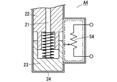
- FIG. 8 discloses an electromagnetic switching device A4 according to the fourth embodiment.
- the measuring unit 5 in this embodiment has a slide-type variable resistor 54 housed in the cap 24, and a slide knob (not shown) of the variable resistor 54 is displaced in conjunction with the movable core 23. It is configured as follows. That is, since the resistance value of the variable resistor 54 changes according to the displacement of the movable iron core 23 (displacement of the movable contact 11), the measuring unit 5 opens and closes the contact portion 1 based on the change of the resistance value. And the number of times of opening and closing can be measured. For example, the measurement unit 5 supplies a constant direct current to the variable resistor 54 and detects a change in the resistance value by detecting the voltage across the variable resistor 54. Alternatively, the measuring unit 5 detects a change in the resistance value by applying a constant DC voltage to the series circuit of the variable resistor 54 and the fixed resistor, and detecting the potential at the connection point between them.
- variable resistor 54 since only a small amount of DC current or DC voltage is supplied to the variable resistor 54 (or the series circuit of the variable resistor 54 and the fixed resistor), a high-frequency current is passed through the detection coil 53. Thus, an increase in power consumption of the measuring unit 5 can be suppressed.
- the displacement of the movable iron core 23 can be detected by a magnetic sensor 55 using a Hall element.
- the position of the permanent magnet 51 attached to the lower surface of the movable iron core 23 is detected by a magnetic sensor 55 arranged below the cap 24.
- the magnetic sensor 55 may be disposed on the side surface of the cap 24 as shown in FIG.
- the permanent magnet 51 is attached to the tip (lower end) of the support member 52 provided on the bottom surface of the movable iron core 23.
- the magnetic sensor 55 may be disposed below the cap 24, and the permanent magnet 51 may be attached to the lower surface of the magnetic sensor 55.
- the contact of the electromagnetic switching device A4 in FIG. 8 has the fixed contact 10 and the movable contact 11.
- the electromagnetic switching device A4 has a displacement means for displacing the movable contact 11.
- the measuring means is configured to measure the number of times the contact is opened and closed based on the displacement of the movable contact 11 by the displacing means.
- the contact has a fixed contact 10 and a movable contact 11.
- the electromagnetic switch A4 has a movable iron core 23.
- the measuring means has a variable resistor.
- the movable iron core 23 is configured to be movable between a first position and a second position.
- the movable iron core 23 is configured to be moved between a first position and a second position by a magnetic field, whereby the contact is opened and closed.
- the resistance value of the variable resistor is configured to change according to the change in the position of the movable iron core 23.
- the measuring means is configured to measure the number of times the contact is opened and closed based on a change in the resistance value of the variable resistor.
- the measurement unit 5 in the present embodiment detects distortion caused by an external force applied for displacement of the movable contact 11, and based on the magnitude of the distortion, displacement of the movable contact 11, that is, opening of the contact 1
- the number of opening and closing can be measured by detecting the closing.
- the movable contact 11 receives the spring force of the contact pressure spring, and the spring force changes between when the contact portion 1 is opened and when the contact portion 1 is opened. Therefore, the measuring unit 5 is attached to the movable contact 11.
- the opening and closing of the contact portion 1 can be detected based on the detection output of the strain gauge (strain sensor).
- strain gauge strain sensor
- the place where the strain gauge is attached is not limited to the movable contact 11, and the sealing container 12 and other parts, particularly those where the amount of strain due to external force is relatively large are desirable.
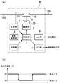
- the measurement unit 5 in the present embodiment measures the number of times the contact unit 1 is opened and closed based on a voltage applied to the contact unit 1 (hereinafter referred to as an inter-contact voltage) as shown in FIG.
- the measuring unit 5 has a resistor (not shown) connected between the pair of fixed contacts 10 and detects the voltage between the contacts by a voltage drop generated in the resistor. That is, when the contact portion 1 is open, the absolute value of the voltage between the contacts is a relatively high voltage value V1, and when the contact portion 1 is closed, the absolute value of the voltage between the contacts is relatively high. A low voltage value (voltage value close to zero) V0 is obtained (see FIG. 10B).
- the measuring unit 5 may measure the number of opening and closing of the contact unit 1 as one when the falling of the absolute value of the voltage between the contacts from the voltage V1 to V0 is detected, or the absolute value of the voltage between the contacts.
- the number of opening and closing of the contact portion 1 may be measured as one.
- the power consumption of the resistor for detecting the voltage between the contacts is very small, an increase in the power consumption of the measuring unit 5 is suppressed as compared with the third embodiment in which a high-frequency current is passed through the detection coil 53. be able to.
- the electromagnetic switching device A7 of the present embodiment has the same basic configuration as that of the first embodiment except that the timer 30 is provided as shown in FIG.
- the same reference numerals are given to the elements, and description thereof will be omitted as appropriate.
- chattering a phenomenon that the contact portion 1 momentarily opens and closes when vibration or impact is applied may occur.
- chattering is considered to increase in the number of occurrences due to factors such as wear of the fixed contact 10 and the movable contact 11 or a decrease in spring force of the contact pressure spring.
- the life determination unit 6 determines the state (life) of the contact part 1 based on the number of times the contact part 1 is opened and closed per predetermined time.
- the predetermined time is the time from the time t1 when the contact-on control signal is input to the input unit 4 to the time t6 when the contact-off control signal is input (hereinafter referred to as contact-on). This is called a control period.
- the time lag (t6 to t7) until the contact portion 1 is actually opened is called the operation time and the return time, respectively.
- an intermittent opening / closing phenomenon called contact bounce occurs when the contact portion 1 is opened and closed. Since this contact bounce is a phenomenon that always occurs due to the mechanism of the electromagnetic switching device, it is desirable not to count the number of times the contact portion 1 is opened and closed due to the contact bounce. Accordingly, the measuring unit 5 counts the total number of opening / closing operations from the time when the operation time elapses until the predetermined contact bounce time (t2 to t3) elapses (t1 to t3) to one time.
- the life determination unit 6 compares the number of opening / closing of the contact unit 1 generated during the contact ON control period with a predetermined threshold value stored in the storage unit 7, and the number of opening / closing times is less than the threshold value. It is determined that the end of life is not reached. On the other hand, if the number of times of opening and closing is equal to or greater than the threshold value, the life determination unit 6 determines that the end of life has been reached.
- life management becomes easier than in the prior art.
- the life judgment part 6 is based on the accumulated time of the excitation coil 20 being energized, that is, the time when the contact part 1 is closed. It is preferable to make a judgment.
- the accumulated time is counted by the timer 30 and the accumulated time stored in the storage unit 7 is updated every time the contact unit 1 is opened.
- the temperature of the exciting coil 20 may be measured by the measuring unit 5, and the life determination unit 6 may adjust the threshold value to be compared with the accumulated time based on the temperature measurement result. For example, as the temperature of the exciting coil 20 increases, the life determination unit 6 may decrease (shorten) the threshold value.
- the determining means is configured to determine the state of the contact based on the number of times of opening / closing the contact per predetermined time.
- the measuring means may measure an accumulated time during which the contact is closed.
Landscapes
- Physics & Mathematics (AREA)
- Electromagnetism (AREA)
- General Physics & Mathematics (AREA)
- Contacts (AREA)
- Testing Electric Properties And Detecting Electric Faults (AREA)
- Arc-Extinguishing Devices That Are Switches (AREA)
Abstract
Priority Applications (2)
| Application Number | Priority Date | Filing Date | Title |
|---|---|---|---|
| US14/004,892 US9097766B2 (en) | 2011-03-22 | 2012-03-09 | Electromagnetic opening/closing device |
| CN201280014004.4A CN103477410B (zh) | 2011-03-22 | 2012-03-09 | 电磁开关装置 |
Applications Claiming Priority (2)
| Application Number | Priority Date | Filing Date | Title |
|---|---|---|---|
| JP2011063233A JP5771779B2 (ja) | 2011-03-22 | 2011-03-22 | 電磁開閉装置 |
| JP2011-063233 | 2011-03-22 |
Publications (1)
| Publication Number | Publication Date |
|---|---|
| WO2012128075A1 true WO2012128075A1 (fr) | 2012-09-27 |
Family
ID=46879229
Family Applications (1)
| Application Number | Title | Priority Date | Filing Date |
|---|---|---|---|
| PCT/JP2012/056101 Ceased WO2012128075A1 (fr) | 2011-03-22 | 2012-03-09 | Dispositif d'ouverture/de fermeture électromagnétique |
Country Status (4)
| Country | Link |
|---|---|
| US (1) | US9097766B2 (fr) |
| JP (1) | JP5771779B2 (fr) |
| CN (1) | CN103477410B (fr) |
| WO (1) | WO2012128075A1 (fr) |
Cited By (3)
| Publication number | Priority date | Publication date | Assignee | Title |
|---|---|---|---|---|
| CN103728556A (zh) * | 2013-12-27 | 2014-04-16 | 河南辉煌科技股份有限公司 | 一种开关状态信号采集方法及开关状态信号采集电路 |
| JP2021118183A (ja) * | 2020-01-24 | 2021-08-10 | シュネーデル、エレクトリック、インダストリーズ、エスアーエスSchneider Electric Industries Sas | 電磁アクチュエータ、およびこの種の電磁アクチュエータを備える電気スイッチング・ユニット |
| WO2024111446A1 (fr) * | 2022-11-21 | 2024-05-30 | パナソニックIpマネジメント株式会社 | Relais électromagnétique et système de détection |
Families Citing this family (25)
| Publication number | Priority date | Publication date | Assignee | Title |
|---|---|---|---|---|
| KR101926864B1 (ko) | 2012-06-26 | 2018-12-07 | 현대자동차주식회사 | 차량 배터리시스템의 릴레이모듈 |
| JP6071503B2 (ja) * | 2012-12-10 | 2017-02-01 | 東光東芝メーターシステムズ株式会社 | ラッチングリレー及び電力量計 |
| JP5660236B1 (ja) * | 2014-02-27 | 2015-01-28 | オムロン株式会社 | 電磁継電器の異常検出方法、電磁継電器の異常検出回路、及び、異常検出システム |
| KR102310530B1 (ko) * | 2014-08-21 | 2021-10-13 | 주식회사 위니아딤채 | 인버터 드라이버의 전원 단속용 릴레이 제어 방법 |
| US10590770B2 (en) * | 2015-03-06 | 2020-03-17 | Snap-On Incorporated | Reversing mechanism for a power tool |
| FR3040526B1 (fr) * | 2015-08-24 | 2017-08-25 | Zodiac Aero Electric | Element de commutation pour plaque de distribution d'energie electrique et boitier de distribution d'energie electrique dote d'un tel element de commutation |
| DE102016101501B4 (de) * | 2016-01-28 | 2018-12-27 | Phoenix Contact Gmbh & Co. Kg | Elektromechanisches Relais und Vorrichtung zum Erkennen des Schaltzustandes eines elektromechanischen Relais |
| DE102016107127B4 (de) * | 2016-01-29 | 2025-12-18 | Tdk Electronics Ag | Relais |
| CN107026040A (zh) * | 2016-01-29 | 2017-08-08 | 德昌电机(深圳)有限公司 | 开关 |
| JP7117567B2 (ja) * | 2017-01-11 | 2022-08-15 | パナソニックIpマネジメント株式会社 | 接点装置、電磁継電器、電気機器 |
| AT519097B1 (de) * | 2017-02-16 | 2018-04-15 | Walter Degelsegger Ing | Schwenktür |
| CN107293447A (zh) * | 2017-07-13 | 2017-10-24 | 芜湖泰领信息科技有限公司 | 时间继电器 |
| KR102537548B1 (ko) * | 2018-01-22 | 2023-05-26 | 엘에스일렉트릭(주) | 보조접점이 구비된 직류 릴레이 |
| JP6600021B2 (ja) * | 2018-02-08 | 2019-10-30 | ファナック株式会社 | 負荷駆動装置および負荷駆動方法 |
| DE102018114559A1 (de) * | 2018-06-18 | 2019-12-19 | Tdk Electronics Ag | Schaltvorrichtung |
| DE102018120987A1 (de) * | 2018-08-28 | 2020-03-05 | Tdk Electronics Ag | Schaltvorrichtung |
| JP7047739B2 (ja) * | 2018-12-10 | 2022-04-05 | オムロン株式会社 | 継電器状態判定装置、継電器状態判定システム、継電器状態判定方法、およびプログラム |
| JP6668518B1 (ja) * | 2019-01-30 | 2020-03-18 | マレリ株式会社 | リレー装置及びリレー装置の制御方法 |
| US11199587B2 (en) * | 2019-03-06 | 2021-12-14 | The United States Of America, As Represented By The Secretary Of The Navy | Swinging door test system |
| DE102019114208A1 (de) * | 2019-05-28 | 2020-12-03 | Phoenix Contact Gmbh & Co. Kg | Verfahren zur Ausfallvorhersage von Elementarrelais |
| KR102299554B1 (ko) * | 2019-12-19 | 2021-09-07 | 현대제철 주식회사 | 전자접촉기 수명 예측 장치 및 방법 |
| KR102876303B1 (ko) | 2020-08-24 | 2025-10-23 | 주식회사 엘지에너지솔루션 | 콘택터 관리 방법 및 그 방법을 제공하는 배터리 시스템 |
| DE102021119006A1 (de) * | 2021-07-22 | 2023-01-26 | Maschinenfabrik Reinhausen Gmbh | Verfahren und system zum betrieb eines laststufenschalters und laststufenschalter umfassend ein solches system |
| US12111359B2 (en) * | 2021-12-14 | 2024-10-08 | Eaton Intelligent Power Limited | Method of monitoring joint and contact conditions in an electrical network |
| CN118538578A (zh) * | 2024-07-25 | 2024-08-23 | 比亚迪股份有限公司 | 继电器和用电设备 |
Citations (11)
| Publication number | Priority date | Publication date | Assignee | Title |
|---|---|---|---|---|
| JPH02146736U (fr) * | 1989-05-16 | 1990-12-13 | ||
| JPH03226934A (ja) * | 1990-01-31 | 1991-10-07 | Noritz Corp | スイッチ制御回路 |
| JPH05120945A (ja) * | 1991-10-30 | 1993-05-18 | Toshiba Corp | 接点消耗監視装置 |
| JPH0686360A (ja) * | 1992-08-31 | 1994-03-25 | Matsushita Electric Works Ltd | 多重伝送システム |
| JPH08235951A (ja) * | 1995-02-28 | 1996-09-13 | Matsushita Electric Works Ltd | 接点開閉装置 |
| JPH1092282A (ja) * | 1996-09-20 | 1998-04-10 | Toshiba Elevator Technos Kk | 継電器動作検出装置 |
| JPH1092283A (ja) * | 1996-06-13 | 1998-04-10 | Eaton Corp | 接触器の作動を監視する方法 |
| JP2003346620A (ja) * | 2002-05-27 | 2003-12-05 | Toyota Motor Corp | リレー装置 |
| JP2004186052A (ja) * | 2002-12-04 | 2004-07-02 | Mitsubishi Electric Corp | 電磁接触器のコイル駆動回路 |
| JP2006294459A (ja) * | 2005-04-12 | 2006-10-26 | Nec Tokin Corp | 電磁継電器 |
| JP2010103099A (ja) * | 2008-09-25 | 2010-05-06 | Panasonic Electric Works Co Ltd | ハイブリッドリレー |
Family Cites Families (6)
| Publication number | Priority date | Publication date | Assignee | Title |
|---|---|---|---|---|
| JPS61274514A (ja) * | 1985-05-30 | 1986-12-04 | Nec Home Electronics Ltd | 接点出力計数方法および装置 |
| US6593802B2 (en) * | 2001-08-14 | 2003-07-15 | Stmicroelectronics, Inc. | On-chip automatic tuning technique |
| US7705601B2 (en) * | 2006-09-21 | 2010-04-27 | Eaton Corporation | Method and apparatus for monitoring wellness of contactors and starters |
| JP4775392B2 (ja) | 2008-03-19 | 2011-09-21 | パナソニック電工株式会社 | 接点装置 |
| KR100882787B1 (ko) * | 2008-09-17 | 2009-02-25 | 주식회사 대륙 | 전자접촉기의 수명예측 장치 |
| US8103460B2 (en) * | 2008-12-16 | 2012-01-24 | Rockwell Automation Technologies, Inc. | Customizable contactor prognostics system |
-
2011
- 2011-03-22 JP JP2011063233A patent/JP5771779B2/ja not_active Expired - Fee Related
-
2012
- 2012-03-09 US US14/004,892 patent/US9097766B2/en not_active Expired - Fee Related
- 2012-03-09 CN CN201280014004.4A patent/CN103477410B/zh not_active Expired - Fee Related
- 2012-03-09 WO PCT/JP2012/056101 patent/WO2012128075A1/fr not_active Ceased
Patent Citations (11)
| Publication number | Priority date | Publication date | Assignee | Title |
|---|---|---|---|---|
| JPH02146736U (fr) * | 1989-05-16 | 1990-12-13 | ||
| JPH03226934A (ja) * | 1990-01-31 | 1991-10-07 | Noritz Corp | スイッチ制御回路 |
| JPH05120945A (ja) * | 1991-10-30 | 1993-05-18 | Toshiba Corp | 接点消耗監視装置 |
| JPH0686360A (ja) * | 1992-08-31 | 1994-03-25 | Matsushita Electric Works Ltd | 多重伝送システム |
| JPH08235951A (ja) * | 1995-02-28 | 1996-09-13 | Matsushita Electric Works Ltd | 接点開閉装置 |
| JPH1092283A (ja) * | 1996-06-13 | 1998-04-10 | Eaton Corp | 接触器の作動を監視する方法 |
| JPH1092282A (ja) * | 1996-09-20 | 1998-04-10 | Toshiba Elevator Technos Kk | 継電器動作検出装置 |
| JP2003346620A (ja) * | 2002-05-27 | 2003-12-05 | Toyota Motor Corp | リレー装置 |
| JP2004186052A (ja) * | 2002-12-04 | 2004-07-02 | Mitsubishi Electric Corp | 電磁接触器のコイル駆動回路 |
| JP2006294459A (ja) * | 2005-04-12 | 2006-10-26 | Nec Tokin Corp | 電磁継電器 |
| JP2010103099A (ja) * | 2008-09-25 | 2010-05-06 | Panasonic Electric Works Co Ltd | ハイブリッドリレー |
Cited By (4)
| Publication number | Priority date | Publication date | Assignee | Title |
|---|---|---|---|---|
| CN103728556A (zh) * | 2013-12-27 | 2014-04-16 | 河南辉煌科技股份有限公司 | 一种开关状态信号采集方法及开关状态信号采集电路 |
| JP2021118183A (ja) * | 2020-01-24 | 2021-08-10 | シュネーデル、エレクトリック、インダストリーズ、エスアーエスSchneider Electric Industries Sas | 電磁アクチュエータ、およびこの種の電磁アクチュエータを備える電気スイッチング・ユニット |
| JP7760247B2 (ja) | 2020-01-24 | 2025-10-27 | シュネーデル、エレクトリック、インダストリーズ、エスアーエス | 電磁アクチュエータ、およびこの種の電磁アクチュエータを備える電気スイッチング・ユニット |
| WO2024111446A1 (fr) * | 2022-11-21 | 2024-05-30 | パナソニックIpマネジメント株式会社 | Relais électromagnétique et système de détection |
Also Published As
| Publication number | Publication date |
|---|---|
| US9097766B2 (en) | 2015-08-04 |
| JP2012199114A (ja) | 2012-10-18 |
| CN103477410B (zh) | 2016-03-23 |
| JP5771779B2 (ja) | 2015-09-02 |
| US20140002092A1 (en) | 2014-01-02 |
| CN103477410A (zh) | 2013-12-25 |
Similar Documents
| Publication | Publication Date | Title |
|---|---|---|
| JP5771779B2 (ja) | 電磁開閉装置 | |
| US9159512B2 (en) | Electromagnetic opening/closing device | |
| US11948757B2 (en) | Contactor with contact carrier location sensing | |
| US8688391B2 (en) | Method for determining contact erosion of an electromagnetic switching device, and electromagnetic switching device comprising a mechanism operating according to said method | |
| JP5842123B2 (ja) | 電磁開閉装置 | |
| US20100082268A1 (en) | Method and apparatus for monitoring a switching process and relay module | |
| CN101341564B (zh) | 用于驱动开关设备的方法和装置 | |
| US10353382B2 (en) | Control member with electronic evaluation of the haptic feedback | |
| EP2724121B1 (fr) | Actionneurs électromagnétiques et leur surveillance | |
| EP4280247A1 (fr) | Relais à verrouillage magnétique à courant continu haute-tension à réponse sensible | |
| US9048049B2 (en) | Electromagnetic opening/closing device | |
| JP2013008621A (ja) | 接点装置及び電磁開閉器 | |
| JP6206697B2 (ja) | 電磁開閉器 | |
| JP2014216142A (ja) | 接点装置の動作状態確認装置 | |
| KR20190020128A (ko) | 중전압 회로 차단기용 액추에이터 | |
| JP2007005208A (ja) | 検出スイッチ | |
| JP5810310B2 (ja) | 接点装置及び電磁開閉器 | |
| JP2005078971A (ja) | 電磁反発駆動電力用開閉装置 | |
| JP2018107046A (ja) | 駆動回路及び接点装置 | |
| KR101116378B1 (ko) | 전자 개폐장치 | |
| JP2007005205A (ja) | 検出スイッチ |
Legal Events
| Date | Code | Title | Description |
|---|---|---|---|
| WWE | Wipo information: entry into national phase |
Ref document number: 201280014004.4 Country of ref document: CN |
|
| 121 | Ep: the epo has been informed by wipo that ep was designated in this application |
Ref document number: 12761019 Country of ref document: EP Kind code of ref document: A1 |
|
| WWE | Wipo information: entry into national phase |
Ref document number: 14004892 Country of ref document: US |
|
| NENP | Non-entry into the national phase |
Ref country code: DE |
|
| 122 | Ep: pct application non-entry in european phase |
Ref document number: 12761019 Country of ref document: EP Kind code of ref document: A1 |