WO2012128103A1 - Structure de joint destinée à un support de pivotement, et support de pivotement - Google Patents
Structure de joint destinée à un support de pivotement, et support de pivotement Download PDFInfo
- Publication number
- WO2012128103A1 WO2012128103A1 PCT/JP2012/056278 JP2012056278W WO2012128103A1 WO 2012128103 A1 WO2012128103 A1 WO 2012128103A1 JP 2012056278 W JP2012056278 W JP 2012056278W WO 2012128103 A1 WO2012128103 A1 WO 2012128103A1
- Authority
- WO
- WIPO (PCT)
- Prior art keywords
- seal
- base
- lip
- groove
- slewing bearing
- Prior art date
- Legal status (The legal status is an assumption and is not a legal conclusion. Google has not performed a legal analysis and makes no representation as to the accuracy of the status listed.)
- Ceased
Links
Images


Classifications
-
- F—MECHANICAL ENGINEERING; LIGHTING; HEATING; WEAPONS; BLASTING
- F16—ENGINEERING ELEMENTS AND UNITS; GENERAL MEASURES FOR PRODUCING AND MAINTAINING EFFECTIVE FUNCTIONING OF MACHINES OR INSTALLATIONS; THERMAL INSULATION IN GENERAL
- F16J—PISTONS; CYLINDERS; SEALINGS
- F16J15/00—Sealings
- F16J15/16—Sealings between relatively-moving surfaces
- F16J15/32—Sealings between relatively-moving surfaces with elastic sealings, e.g. O-rings
- F16J15/3268—Mounting of sealing rings
- F16J15/3276—Mounting of sealing rings with additional static sealing between the sealing, or its casing or support, and the surface on which it is mounted
-
- F—MECHANICAL ENGINEERING; LIGHTING; HEATING; WEAPONS; BLASTING
- F16—ENGINEERING ELEMENTS AND UNITS; GENERAL MEASURES FOR PRODUCING AND MAINTAINING EFFECTIVE FUNCTIONING OF MACHINES OR INSTALLATIONS; THERMAL INSULATION IN GENERAL
- F16C—SHAFTS; FLEXIBLE SHAFTS; ELEMENTS OR CRANKSHAFT MECHANISMS; ROTARY BODIES OTHER THAN GEARING ELEMENTS; BEARINGS
- F16C33/00—Parts of bearings; Special methods for making bearings or parts thereof
- F16C33/72—Sealings
- F16C33/76—Sealings of ball or roller bearings
- F16C33/78—Sealings of ball or roller bearings with a diaphragm, disc, or ring, with or without resilient members
- F16C33/7816—Details of the sealing or parts thereof, e.g. geometry, material
- F16C33/782—Details of the sealing or parts thereof, e.g. geometry, material of the sealing region
- F16C33/7823—Details of the sealing or parts thereof, e.g. geometry, material of the sealing region of sealing lips
-
- F—MECHANICAL ENGINEERING; LIGHTING; HEATING; WEAPONS; BLASTING
- F16—ENGINEERING ELEMENTS AND UNITS; GENERAL MEASURES FOR PRODUCING AND MAINTAINING EFFECTIVE FUNCTIONING OF MACHINES OR INSTALLATIONS; THERMAL INSULATION IN GENERAL
- F16C—SHAFTS; FLEXIBLE SHAFTS; ELEMENTS OR CRANKSHAFT MECHANISMS; ROTARY BODIES OTHER THAN GEARING ELEMENTS; BEARINGS
- F16C33/00—Parts of bearings; Special methods for making bearings or parts thereof
- F16C33/72—Sealings
- F16C33/76—Sealings of ball or roller bearings
- F16C33/78—Sealings of ball or roller bearings with a diaphragm, disc, or ring, with or without resilient members
- F16C33/7816—Details of the sealing or parts thereof, e.g. geometry, material
- F16C33/783—Details of the sealing or parts thereof, e.g. geometry, material of the mounting region
-
- F—MECHANICAL ENGINEERING; LIGHTING; HEATING; WEAPONS; BLASTING
- F16—ENGINEERING ELEMENTS AND UNITS; GENERAL MEASURES FOR PRODUCING AND MAINTAINING EFFECTIVE FUNCTIONING OF MACHINES OR INSTALLATIONS; THERMAL INSULATION IN GENERAL
- F16C—SHAFTS; FLEXIBLE SHAFTS; ELEMENTS OR CRANKSHAFT MECHANISMS; ROTARY BODIES OTHER THAN GEARING ELEMENTS; BEARINGS
- F16C33/00—Parts of bearings; Special methods for making bearings or parts thereof
- F16C33/72—Sealings
- F16C33/76—Sealings of ball or roller bearings
- F16C33/78—Sealings of ball or roller bearings with a diaphragm, disc, or ring, with or without resilient members
- F16C33/7889—Sealings of ball or roller bearings with a diaphragm, disc, or ring, with or without resilient members mounted to an inner race and extending toward the outer race
-
- F—MECHANICAL ENGINEERING; LIGHTING; HEATING; WEAPONS; BLASTING
- F16—ENGINEERING ELEMENTS AND UNITS; GENERAL MEASURES FOR PRODUCING AND MAINTAINING EFFECTIVE FUNCTIONING OF MACHINES OR INSTALLATIONS; THERMAL INSULATION IN GENERAL
- F16J—PISTONS; CYLINDERS; SEALINGS
- F16J15/00—Sealings
- F16J15/16—Sealings between relatively-moving surfaces
- F16J15/32—Sealings between relatively-moving surfaces with elastic sealings, e.g. O-rings
- F16J15/3204—Sealings between relatively-moving surfaces with elastic sealings, e.g. O-rings with at least one lip
- F16J15/3232—Sealings between relatively-moving surfaces with elastic sealings, e.g. O-rings with at least one lip having two or more lips
- F16J15/3236—Sealings between relatively-moving surfaces with elastic sealings, e.g. O-rings with at least one lip having two or more lips with at least one lip for each surface, e.g. U-cup packings
-
- F—MECHANICAL ENGINEERING; LIGHTING; HEATING; WEAPONS; BLASTING
- F16—ENGINEERING ELEMENTS AND UNITS; GENERAL MEASURES FOR PRODUCING AND MAINTAINING EFFECTIVE FUNCTIONING OF MACHINES OR INSTALLATIONS; THERMAL INSULATION IN GENERAL
- F16J—PISTONS; CYLINDERS; SEALINGS
- F16J15/00—Sealings
- F16J15/16—Sealings between relatively-moving surfaces
- F16J15/34—Sealings between relatively-moving surfaces with slip-ring pressed against a more or less radial face on one member
- F16J15/3436—Pressing means
- F16J15/3456—Pressing means without external means for pressing the ring against the face, e.g. slip-ring with a resilient lip
-
- F—MECHANICAL ENGINEERING; LIGHTING; HEATING; WEAPONS; BLASTING
- F05—INDEXING SCHEMES RELATING TO ENGINES OR PUMPS IN VARIOUS SUBCLASSES OF CLASSES F01-F04
- F05B—INDEXING SCHEME RELATING TO WIND, SPRING, WEIGHT, INERTIA OR LIKE MOTORS, TO MACHINES OR ENGINES FOR LIQUIDS COVERED BY SUBCLASSES F03B, F03D AND F03G
- F05B2240/00—Components
- F05B2240/50—Bearings
-
- F—MECHANICAL ENGINEERING; LIGHTING; HEATING; WEAPONS; BLASTING
- F05—INDEXING SCHEMES RELATING TO ENGINES OR PUMPS IN VARIOUS SUBCLASSES OF CLASSES F01-F04
- F05B—INDEXING SCHEME RELATING TO WIND, SPRING, WEIGHT, INERTIA OR LIKE MOTORS, TO MACHINES OR ENGINES FOR LIQUIDS COVERED BY SUBCLASSES F03B, F03D AND F03G
- F05B2240/00—Components
- F05B2240/57—Seals
-
- F—MECHANICAL ENGINEERING; LIGHTING; HEATING; WEAPONS; BLASTING
- F05—INDEXING SCHEMES RELATING TO ENGINES OR PUMPS IN VARIOUS SUBCLASSES OF CLASSES F01-F04
- F05B—INDEXING SCHEME RELATING TO WIND, SPRING, WEIGHT, INERTIA OR LIKE MOTORS, TO MACHINES OR ENGINES FOR LIQUIDS COVERED BY SUBCLASSES F03B, F03D AND F03G
- F05B2260/00—Function
- F05B2260/60—Fluid transfer
- F05B2260/63—Preventing clogging or obstruction of flow paths by dirt, dust, or foreign particles
-
- F—MECHANICAL ENGINEERING; LIGHTING; HEATING; WEAPONS; BLASTING
- F16—ENGINEERING ELEMENTS AND UNITS; GENERAL MEASURES FOR PRODUCING AND MAINTAINING EFFECTIVE FUNCTIONING OF MACHINES OR INSTALLATIONS; THERMAL INSULATION IN GENERAL
- F16C—SHAFTS; FLEXIBLE SHAFTS; ELEMENTS OR CRANKSHAFT MECHANISMS; ROTARY BODIES OTHER THAN GEARING ELEMENTS; BEARINGS
- F16C19/00—Bearings with rolling contact, for exclusively rotary movement
- F16C19/02—Bearings with rolling contact, for exclusively rotary movement with bearing balls essentially of the same size in one or more circular rows
- F16C19/14—Bearings with rolling contact, for exclusively rotary movement with bearing balls essentially of the same size in one or more circular rows for both radial and axial load
- F16C19/16—Bearings with rolling contact, for exclusively rotary movement with bearing balls essentially of the same size in one or more circular rows for both radial and axial load with a single row of balls
-
- F—MECHANICAL ENGINEERING; LIGHTING; HEATING; WEAPONS; BLASTING
- F16—ENGINEERING ELEMENTS AND UNITS; GENERAL MEASURES FOR PRODUCING AND MAINTAINING EFFECTIVE FUNCTIONING OF MACHINES OR INSTALLATIONS; THERMAL INSULATION IN GENERAL
- F16C—SHAFTS; FLEXIBLE SHAFTS; ELEMENTS OR CRANKSHAFT MECHANISMS; ROTARY BODIES OTHER THAN GEARING ELEMENTS; BEARINGS
- F16C2300/00—Application independent of particular apparatuses
- F16C2300/10—Application independent of particular apparatuses related to size
- F16C2300/14—Large applications, e.g. bearings having an inner diameter exceeding 500 mm
-
- F—MECHANICAL ENGINEERING; LIGHTING; HEATING; WEAPONS; BLASTING
- F16—ENGINEERING ELEMENTS AND UNITS; GENERAL MEASURES FOR PRODUCING AND MAINTAINING EFFECTIVE FUNCTIONING OF MACHINES OR INSTALLATIONS; THERMAL INSULATION IN GENERAL
- F16C—SHAFTS; FLEXIBLE SHAFTS; ELEMENTS OR CRANKSHAFT MECHANISMS; ROTARY BODIES OTHER THAN GEARING ELEMENTS; BEARINGS
- F16C2360/00—Engines or pumps
- F16C2360/31—Wind motors
-
- F—MECHANICAL ENGINEERING; LIGHTING; HEATING; WEAPONS; BLASTING
- F16—ENGINEERING ELEMENTS AND UNITS; GENERAL MEASURES FOR PRODUCING AND MAINTAINING EFFECTIVE FUNCTIONING OF MACHINES OR INSTALLATIONS; THERMAL INSULATION IN GENERAL
- F16C—SHAFTS; FLEXIBLE SHAFTS; ELEMENTS OR CRANKSHAFT MECHANISMS; ROTARY BODIES OTHER THAN GEARING ELEMENTS; BEARINGS
- F16C33/00—Parts of bearings; Special methods for making bearings or parts thereof
- F16C33/30—Parts of ball or roller bearings
- F16C33/58—Raceways; Race rings
- F16C33/583—Details of specific parts of races
Definitions
- the present invention is, for example, a swivel used for a swivel part of various machines used in the vicinity of the outdoors or indoors, such as a swivel seat for a yaw and a blade of a wind power generator, a deck crane, a construction machine, and a lifting machine.
- the present invention relates to a seal structure of a bearing and a slewing bearing.
- Slewing bearings used for wind power generation devices such as yaw and swivel seats for blades are generally lubricated with grease.
- This slewing bearing is provided with a rubber seal in order to prevent foreign matters from entering from outside or grease leakage from inside the bearing (Patent Documents 1 and 2).
- Nitrile, chloroprene, acrylic, etc. are used as the material of this rubber.
- rubber seals used for slewing bearings for yaw and blades of wind power generators have an important function of preventing grease leakage from the viewpoint of protecting the surrounding environment. Since the slewing bearing is generally operated at a low speed, there is little problem of heat generation. However, as shown in FIG. 14, when additional grease is supplied from the greasing pipe 50, the pressure inside the bearing having the shaft center C is increased. Rises. As shown in the figure, the grease supply pipe 50 is a pipe that penetrates radially from the outer ring outer diameter surface 51 or the inner ring inner diameter surface 52 toward the bearing interior. As described above, since the pressure inside the bearing rises, the internal pressure acts on the rubber seal portion 53.
- the direction of the seal lip 55 is two patterns: an inward lip 55a extending inwardly in the axial direction of the bearing space as it goes toward the tip, and an outward lip 55b extending inclining outward in the axial direction of the bearing space as it goes toward the tip. is there.
- an inward lip 55a is required.
- the inward lip 55a is applied with pressure higher than expected, there is a problem that the lip is reversed.
- the sealing torque increases, which may affect the specifications of the drive device, that is, it may be necessary to increase the capacity of the turning torque.
- An object of the present invention is to provide a seal structure for a slewing bearing and a slewing bearing that can prevent the lip portion of the seal member from being reversed and the seal member from falling off when the internal pressure is increased, and can reduce the seal torque. .
- a raceway groove is formed in each of the race rings of the inner ring and the outer ring, a plurality of rolling elements are provided between the race grooves of the inner and outer rings, and at the axial ends of the inner and outer rings, A step that is uneven in the axial direction is provided between the inner and outer rings, and an elastic seal member that seals the axial end of the inner and outer rings having the step is provided.
- the seal member includes a base fixed to a portion protruding from the concave raceway of the convex raceway that is the convex side of the step, and one or more that are in contact with the concave raceway that is the concave side of the step.
- One of the lip portions includes a main lip extending obliquely so as to be positioned on the inner side in the axial direction of the bearing space toward the tip, and on the bearing space side of the concave bearing ring.
- a seal slidable contact surface portion that slidably contacts the main lip of the seal member, and an annular protruding portion that protrudes in the radial direction is provided on the end side of the peripheral surface of the concave raceway.
- a seal sliding side inclined portion that is inclined so as to be positioned on the outer side in the axial direction toward the protruding tip.
- An annular groove is provided on the peripheral surface of the convex raceway, and a fixing groove is provided on an outer surface in the axial direction at the bottom of the annular groove, and the base portion of the seal member includes the peripheral surface of the convex raceway and the circumferential surface.
- a seal fixing side inclined portion that is inclined so as to be positioned on the side is provided.
- the main lip when internal pressure is applied to the seal member, the main lip is pressed against the seal sliding side inclined portion of the annular projection of the concave raceway, and the base is inclined to the seal fixing side of the convex raceway. Pressed against the part. That is, the main lip and the base of the seal member are both supported by the race ring.
- the main lip and the base portion come into contact with the respective inclined portions facing each other, the inversion of the lip portion can be suppressed, and the seal member can be prevented from falling off the raceway. Accordingly, in order to prevent the lip portion from being reversed, it is not necessary to increase the lip rigidity by increasing the thickness of the lip portion. Therefore, the thickness of the lip portion can be made thinner than that of the conventional one, and the sealing torque can be reduced.
- the inner surface of the base portion facing the bottom of the annular groove of the convex raceway ring may be connected by a single curved surface or a continuous curved surface having no inflection point.
- the inner surface of the base portion facing the bottom portion of the annular groove of the convex raceway ring may be connected to a plurality of surfaces having intersection angles of 90 degrees or more and 180 degrees or less.
- the “intersection angle” refers to an angle viewed from the inside of the seal member. In these cases, the rigidity of the base portion of the seal member can be increased and local deformation can be prevented.
- the angle of the intersection line connecting the axial inner side surface of the main lip and the base inner side surface of the base may be 180 degrees or more and 270 degrees or less.
- the “angle” refers to an angle viewed from the inside of the seal member.
- the main lip can be positively elastically deformed by applying an internal pressure to a portion connecting the axial inner side surface of the main lip and the base inner side surface of the base portion. Thereby, even if it is a case where the hooking amount of a base is small with respect to an annular wall part, it can prevent that the sealing member is pulled out by the base side.
- the seal slide is formed so that the surface of the annular protrusion extending from the seal sliding side inclined portion toward the convex raceway and the surface of the fixing groove extending from the seal fixing side inclined portion toward the concave raceway are crossed.
- a moving side inclined portion and a seal fixing side inclined portion may be provided.
- the surface where the seal sliding side inclined portion is extended to the convex bearing ring side and the surface where the seal fixing side inclined portion of the fixing groove is extended to the concave bearing ring side are brought close to one plane so that the sealing member When the internal pressure is applied, the main lip and the base of the seal member can be more reliably brought into contact with the surface.
- the main lip may be thinner than the base.
- the seal torque of the lip portion can be reduced, and the main lip can be positively elastically deformed when an internal pressure is applied to the seal member.
- the main lip is surely pressed against the seal sliding side inclined portion of the annular projection of the concave raceway, so that the sealing member can be used even when the hooking amount of the base portion is small relative to the annular wall portion. Can be prevented from coming out on the base side.
- the bottom surface of the fitting groove of the seal base or the side surface of the groove on the bearing space side may be brought into contact with the seal base.
- the coefficient of friction is increased, the fixation of the seal base can be stabilized, and the suppression of grease leakage from the fixed part can be enhanced. Further, since the tightness of the seal lip can be maintained, the sealing performance can be stabilized.
- the sealing member may be made of nitrile or chloroprene.
- the seal member may include, as one of the lip portions, a sub lip branched from the base portion separately from the main lip and in contact with the end surface of the concave raceway. By this sub lip, the sealing performance of the sealing member is further maintained, and grease leakage from the bearing space can be prevented.
- the initial tightening allowance of the main lip may be 2 mm or more and 6 mm or less. By setting such an initial tightening allowance, it is possible to reduce the seal torque and prevent grease leakage from the bearing space.
- the slewing bearing of the present invention is one to which any of the above-mentioned seal structures is applied.
- a wind turbine blade may be supported so as to be rotatable about an axis substantially perpendicular to the main shaft axis with respect to the main shaft.
- the nacelle of the windmill may be supported so as to be rotatable with respect to the support base.
- This slewing bearing is, for example, a bearing that supports the blade of a wind turbine for wind power generation so that it can pivot about an axis substantially perpendicular to the main shaft axis or a nacelle of the wind turbine relative to a support base. Used as a bearing to support.
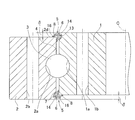
- the slewing bearing is adjacent to the inner ring 1, the outer ring 2, and a plurality of balls 3 that are rotatably interposed between the raceway grooves 1 a and 2 a of the inner and outer rings 1 and 2.
- a spacer (not shown) interposed between the balls 3 and 3 and a seal member 5 described later are provided.
- Each of the raceway grooves 1a and 2a of the inner and outer rings 1 and 2 is composed of two curved surfaces.
- the two curved surfaces constituting each raceway groove 1a, 2a are Gothic arch-shaped arcs having a larger radius of curvature than the balls 3 as rolling elements and different curvature centers.
- Each ball 3 is in contact with the curved surfaces of the inner ring raceway groove 1a and the outer ring raceway groove 2a at a point of contact with each other at four points.
- This slewing bearing is configured as a four-point contact ball bearing.
- the spacer is made of, for example, a resin material, and the spacer has a concave shape in which the ball contact surfaces on both sides form a spherical surface that is deeply recessed toward the center.
- the outer ring 2 is provided with a plurality of through holes 2b at regular intervals in the circumferential direction. These through holes 2b are used, for example, for connecting and fixing the outer ring 2 to a support base 22 (FIGS. 7 and 8) described later.
- the inner ring 1 is also provided with a plurality of through holes 1b at regular intervals in the circumferential direction, and these through holes 1b are used for connecting and fixing the inner ring 1 to, for example, a casing 24 (FIGS. 7 and 8) of a nacelle 23 described later. Used for.
- Each through-hole 1b, 2b is formed in parallel with the bearing axial direction.
- steps ⁇ that are uneven in the axial direction between the inner and outer rings 1 and 2 are provided at the axial ends of the inner and outer rings 1 and 2, in this example, at both ends in the axial direction.
- the bearing space 4 of the inner and outer rings 1 and 2 is filled with grease, and the seal members 5 and 5 seal both axial ends of the inner and outer rings 1 and 2 having the step ⁇ .
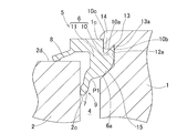
- the seal member 5 at one end in the axial direction (upper part in FIG. 1) will be described.
- the convex raceway that is the convex side of the step ⁇ is the inner ring 1
- the concave raceway that is the concave side of the step ⁇ is the outer ring 2.
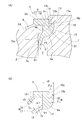
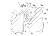
- the seal member 5 is made of an elastic body such as nitrile or chloroprene, and has a base portion 6 and a lip portion 9 including a main lip 7 and a sub lip 8 as shown in FIG.
- the base portion 6 and the lip portion 9 are provided integrally.
- the base portion 6 includes a seal fixing portion 10 that is fixed to the inner ring 1 that is a convex raceway ring, and a seal body portion 11 that is connected to the seal fixing portion 10.
- a fitting groove 10 a is provided on the inner peripheral surface side of the seal fixing portion 10 of the base portion 6.
- the fitting groove 10a is formed so as to open annularly outward in the axial direction.
- the seal fixing portion 10 of the base portion 6 is fixed to a portion of the inner ring 1 that protrudes in the axial direction from the outer ring 2.
- An annular groove 12 is provided on the outer peripheral surface of the inner ring 1, and a fixed groove 13 recessed in a V shape toward the axially outer side (side away from the bearing space 4) on the axially outer surface at the bottom of the annular groove 12. Is provided.
- a seal fixed side inclined portion 13 a that is inclined so as to be positioned outward in the axial direction toward the groove bottom side portion.
- the largest radial clearance between the tip portion 10b of the seal fixing portion 10 and the engaging portion 10c. ⁇ a is formed to be narrower than when the seal fixing portion 10 is fixed to the inner ring 1 (FIG. 2A).
- the tip portion 10b of the seal fixing portion 10 is elastically deformed radially inward (in other words, the seal fixing part 10 is in contact with the seal fixing side inclined part 13a (separated from the engaging part 10c).
- the engaging portion 10 c of the seal fixing portion 10 is engaged with the step portion 1 c of the inner ring 1.
- the inner side surface 15 on the inner side in the axial direction at the bottom of the annular groove 12 is formed, for example, in parallel with the inclined surface of the seal fixing side inclined portion 13a, and the base portion 6 of the seal member 5 does not interfere with the inner side surface 15 and the groove bottom surface. It is provided as follows. Of the base 6 of the seal member 5, the base inner side surface 6 a facing the bottom of the annular groove 12 is formed as a shape connected with a single curved surface or a continuous curved surface having no inflection point, forming a curved surface inward in the radial direction. Yes.
- the main lip 7 of the lip portion 9 extends in an inclined manner so as to be located on the inner side in the axial direction of the bearing space toward the tip.
- the main lip 7 extends obliquely inward in the axial direction from the outer surface of the seal body 11 facing the inner peripheral surface of the outer ring of the seal body 11.
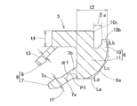
- the thickness t1 of the main lip 7 is provided to be thinner than the maximum radial thickness t2 of the seal body 11 of the base 6.
- the angle ⁇ 1 of the line connecting the base inner surface 6a facing the bottom of the annular groove 12 and the axial inner surface 7a of the main lip 7 is 180 degrees or more and 270 degrees or less. .
- the base inner side surface 6a is connected by a single curved surface or a continuous curved surface having no inflection point, the tangent line La passing through the axial inner side surface of the main lip 7 of the base inner side surface 6a
- the angle ⁇ 1 of the intersection line connecting the axially inner side surfaces of the main lip 7 is set as described above.
- the “angle” refers to an angle viewed from the inside of the seal member 5.
- the initial fastening allowance of the main lip 7 (the amount of change in the radial position of the tip of the main lip 7 before and after assembling into the bearing) is set to 2 mm or more and 6 mm or less.
- a seal sliding contact surface portion 2c for slidingly contacting the main lip 7 is provided on the inner peripheral surface of the outer ring 2 on the bearing space side of the outer ring 2 that is a concave raceway.
- An annular projecting portion 16 projecting in the radial direction is provided on the inner peripheral surface of the outer ring on the end side of the seal sliding contact surface portion 2c.
- a seal sliding side inclined portion 16a that is inclined so as to be positioned on the outer side in the axial direction toward the protruding tip is provided on the inner surface in the axial direction facing the bearing space in the annular protruding portion 16.
- seal sliding side slope 16 so that the surface S2 extending the seal sliding side inclined portion 16a to the inner ring 1 side and the surface S1 extending the seal fixing side inclined portion 13a of the fixing groove 13 to the outer ring 2 side intersect.
- a portion 16a and a seal fixing side inclined portion 13a are provided.
- the auxiliary lip 8 of the lip portion 9 branches from the seal body portion 11 of the base portion 6 separately from the main lip 7 and contacts the end surface 2d of the outer ring 2. That is, the sub lip 8 extends in an axially inclining manner from the lower end surface portion of the seal body portion 11 facing the end surface 2d of the outer ring 2, and makes axial contact with the end surface 2d of the outer ring 2. As shown in FIG. 2B, the thickness t3 of the sub lip 8 is provided thinner than the thickness t4 of the seal body 11 in the axial direction.
- the secondary lip 8 is also called a dust lip.
- the convex raceway ring that is the convex side of the step ⁇ is the outer ring 2
- the concave side of the step ⁇ is the inner ring 1. Since the seal structure provided at the other end in the axial direction is the same as the seal structure at one end in the axial direction, the same reference numerals as those assigned to the seal structure are attached and the description thereof is omitted.
- the main lip 7 is pressed against the seal sliding side inclined portion 16a of the annular protrusion 16 of the concave raceway, and the base portion 6 is pressed against the seal fixing side inclined portion 13a of the convex raceway. That is, the main lip 7 and the base 6 of the seal member 5 are both supported by the raceway ring. At this time, the main lip 7 and the base portion 6 come into contact with the respective inclined portions 16a and 13a facing each other, so that the inversion of the lip portion 9 can be suppressed and the seal member 5 is prevented from falling off the raceway. can do. Accordingly, in order to prevent the lip portion from being reversed, it is not necessary to increase the lip rigidity by increasing the thickness of the lip portion. Therefore, the thickness of the lip portion 9 can be made thinner than that of the conventional one, and the sealing torque can be reduced.
- the seal member 5 by inserting the base portion 6 of the seal member 5 into the fixed groove 13 provided on the peripheral surface of the convex side race ring, the annular wall portion 14 between the peripheral surface of the convex side race ring and the inner surface of the fixed groove 13 is formed. Since it fits in the fitting groove 10a of the base 6, the seal member 5 can be easily fixed to the convex raceway. Therefore, the number of assembly steps can be reduced. In this case, an adhesive or the like for fixing the seal member 5 is not necessary, and other components such as a lid for suppressing the seal are also unnecessary, so that the number of components can be reduced and the manufacturing cost can be reduced. The workability when replacing the worn seal member 5 is also greatly improved as compared with the prior art.
- the base inner side surface 6 a facing the bottom of the annular groove 12 has a shape connected by a single curved surface or a continuous curved surface having no inflection point.
- the rigidity can be increased and local deformation can be prevented.
- the angle ⁇ 1 of the line connecting the axial inner side surface 7a of the main lip 7 and the base inner side surface 6a of the base 6 is set to 180 degrees or more and 270 degrees or less.
- the main lip 7 can be positively elastically deformed by applying an internal pressure to a portion P ⁇ b> 1 connecting the axial inner side surface 7 a and the base inner side surface 6 a of the base 6.
- the surface S2 of the annular protrusion 16 extending the seal sliding side inclined portion 16a to the convex raceway side, and the seal fixing side inclined portion 13a of the fixing groove 13 is set to the concave side track. Since the seal sliding side inclined portion 16a and the seal fixing side inclined portion 13a are provided so as to intersect with the surface S1 extended to the ring side, the following effects are obtained. That is, the surface S2 obtained by extending the seal sliding side inclined portion 16a toward the convex raceway and the surface S1 obtained by extending the seal fixing side inclined portion 13a of the fixing groove 13 toward the concave raceway are close to one plane. When the internal pressure is applied to the seal member 5, the main lip 7 and the base portion 6 of the seal member 5 can be brought into contact with each other more reliably.
- the thickness t1 of the main lip 7 is provided thinner than the radial thickness t2 of the seal body 11 of the base 6, so that the seal torque of the main lip 7 is reduced.
- the main lip 7 can be positively elastically deformed.
- the main lip 7 is surely pressed against the seal sliding side inclined portion 16a of the annular projection 16 of the concave raceway ring, so that the base 6 is less likely to be caught with respect to the annular wall portion 14.
- the seal member 5 includes the secondary lip 8 that contacts the end surface 2d of the outer ring 2, the secondary lip 8 can further maintain the sealing performance of the seal member 5 and prevent grease leakage from the bearing space 4. Since the secondary lip 8 is in axial contact, the sealing torque can be reduced more than the lip portion in radial contact.
- the base inner surface 6a facing the bottom of the annular groove 12 of the base 6 of the seal member 5 is intersected at an angle of 90 degrees or more and 180 degrees or less. It is good also as the shape connected with the some surface (two surfaces in the example of FIG. 3) which has angle (alpha) 2.
- the “intersection angle” ⁇ 2 refers to an angle viewed from the inside of the seal member 5. In this case, the rigidity of the base 6 of the seal member 5 can be increased and local deformation can be prevented.
- the bottom surface 12 a of the fitting groove of the base portion 6 of the seal member 5 may be brought into contact with the base portion 6 of the seal member 5, or as in the fourth embodiment shown in FIG. 5.
- the bearing space side groove side surface 12 b of the base portion 6 of the seal member 5 and the base portion 6 of the seal member 5 may be brought into contact with each other.
- the bottom surface 12 a is a bottom surface of the annular groove 12 provided on the outer peripheral surface of the inner ring 1
- the bearing space side groove side surface 12 b is an annular surface provided on the outer peripheral surface of the inner ring 1. It is an inner surface on the inner side in the axial direction at the bottom of the groove 12.
- the bottom surface 12 a of the fitting groove and the bearing space side groove side surface 12 b may be brought into contact with the seal base 6.
- the configurations of the third to fifth embodiments shown in FIGS. 4 to 6 can increase the friction coefficient, stabilize the fixation of the seal base 6, and enhance the suppression of grease leakage from the fixed portion. . Further, since the tightness of the seal lip can be maintained, the sealing performance can be stabilized.
- FIG. 7 and 8 show an example of a wind turbine for wind power generation.
- a nacelle 23 is provided on a support base 22 so as to be horizontally rotatable, a main shaft 25 is rotatably supported in a casing 24 of the nacelle 23, and a casing 24 of the main shaft 25 is supported.
- a blade 26 which is a swirl blade is attached to one end protruding outward.
- the other end of the main shaft 25 is connected to the speed increaser 27, and the output shaft 28 of the speed increaser 27 is coupled to the rotor shaft of the generator 29.
- the nacelle 23 is rotatably supported by a swing bearing BR1.
- a slewing bearing BR1 for the nacelle 23 having a gear or the like provided on the outer peripheral surface of the outer ring 2 is used.
- a plurality of drive sources 30 are installed in the casing 24, and pinion gears are fixed to the drive sources 30 via a reduction gear (not shown). It arrange
- the outer ring 2 is connected and fixed to the support base 22 by a plurality of through holes 2 b, and the inner ring 1 is fixed to the casing 24.
- the plurality of drive sources 30 are driven in synchronization, and this turning driving force is transmitted to the outer ring 2. Therefore, the nacelle 23 can turn relative to the support base 22.
- the blade 26 is rotatably supported by the slewing bearing BR2.
- this slewing bearing BR2 in the slewing bearing of any of the embodiments described above, for example, a structure in which a gear is provided on the inner peripheral surface of the inner ring 1 is applied.
- a driving source for rotating the blade 26 is provided at the protruding end portion 25 a of the main shaft 25.
- the outer ring 2 of the slewing bearing is connected and fixed to the distal end portion 25a, and a gear attached to the inner peripheral surface of the inner ring 1 is engaged with a pinion gear of the drive source 30 (FIG. 7).
- the slewing bearing BR2 can support the wind turbine blade 26 with respect to the main shaft 25 so as to be rotatable about an axis L2 substantially perpendicular to the main shaft axis L1. In this way, the angle of the blade 26 and the direction of the nacelle 23 can be changed at any time according to the wind condition.
- the slewing bearing having any one of the above seal structures When the slewing bearing having any one of the above seal structures is used in a wind turbine for wind power generation, it is possible to prevent the lip portion 9 of the seal member 5 from being reversed and the seal member 5 from dropping off when the internal pressure is increased. As a result, the sealing performance of the seal member 5 can be maintained and grease leakage can be prevented, so that the surrounding environment can be protected and the bearing life can be extended. Further, since the sealing torque can be reduced, it is not necessary to increase the capacity of the turning torque. Therefore, it is possible to reduce the size of the drive source and reduce the manufacturing cost.
- the slewing bearings are used to slew various machines used outdoors or indoors, such as hydraulic excavators other than those for wind power generation, construction machines such as cranes, rotary tables for machine tools, gun seats, parabolic antennas, and lifting machines. It can also be applied to parts.
- the slewing bearing may be one in which the inner and outer rings have double-row raceway grooves or a cylindrical roller type (three-row cylindrical roller, cross roller).
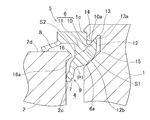
- the main lip 7 of the lip portion 9 includes a lip body portion 7b connected to the base portion 6, and a lip protrusion portion 7c protruding from the lip body portion 7b. And have.
- the lip body portion 7b and the lip protruding portion 7c extend as an entire main lip so as to be positioned on the inner side in the axial direction of the bearing space toward the tip.
- the lip protrusion 7c is thinner than the lip body 7b.
- the lip protrusion 7c is formed in a tapered shape of the cross section that decreases in thickness toward the tip, in other words, a wedge shape.
- the main lip 7 is pressed against the seal sliding contact surface portion 2c of the concave raceway, and the base 6 Is pressed against the seal fixing side inclined portion 13a.
- the cross-sectional shape of the base inner side surface 6a facing the bottom of the annular groove 12 of the convex raceway in the base portion 6 of the seal member 5 is a shape made of one convex curve, The rigidity can be increased and local deformation can be prevented. Thereby, reversal of the lip portion 9 can be suppressed, and the seal member 5 can be prevented from falling off the raceway.
- the thickness of the lip portion 9 can be made thinner than the conventional one, and the seal torque during the bearing operation can be reduced. In addition, the sealing performance of the sealing member 5 is maintained. Since the lip protrusion 7c has a tapered cross section, when the internal pressure is applied to the seal member 5, the entire lip protrusion 7c is firmly pressed along the seal sliding contact surface portion 2c. 9 can be more reliably suppressed.
- the seal member 5 is easily fixed to the convex raceway ring. can do. Therefore, the number of assembly steps and the number of parts can be reduced, and the manufacturing cost can be reduced.
- the angle ⁇ 1 of the intersection line connecting the axial inner side surface 7a of the main lip 7 and the base inner side surface 6a of the base 6 is set to 180 degrees or more and 270 degrees or less. 7 can be positively elastically deformed. Thereby, even when the catching amount of the base portion 6 is small with respect to the annular wall portion 14, the seal member 5 can be prevented from coming out on the base portion 6 side.
- the thickness t1 of the main lip 7 is provided thinner than the radial thickness t2 of the seal body 11 of the base 6, and the thickness of the lip protrusion 7c is provided thinner than the thickness of the lip body 7b. Therefore, the sealing torque of the main lip 7 can be reduced, and when the internal pressure is applied to the seal member 5, the main lip 7 can be positively elastically deformed. As a result, the entire lip projecting portion is more firmly pressed along the seal sliding contact surface portion 2c, so that even if the hooking amount of the base portion 6 is small with respect to the annular wall portion 14, the base portion 6 side of the seal member 5 Can be prevented from coming off.
- the seal member 5 includes the auxiliary lip 8 that is in axial contact with the end surface 2d of the outer ring 2, the auxiliary lip 8 further maintains the sealing performance of the seal member 5 and has a sealing torque higher than that of the lip portion that is in radial contact. Reduction can be achieved.
- the cross-sectional shape of the base inner side surface 6a facing the bottom of the annular groove 12 in the base 6 of the seal member 5 is continuous without an inflection point. It is good also as the shape connected with the convex curve Lb, Lc, Ld which was made. These convex curves Lb, Lc, and Ld each form a convex curved surface inward in the radial direction. Also in this case, the rigidity of the entire seal member 5 can be increased and local deformation can be prevented. Thereby, reversal of the lip portion 9 can be suppressed, and the seal member 5 can be prevented from falling off the raceway.
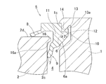
- FIG. 12 shows an application example 3.
- This application example 3 corresponds to the second embodiment shown in FIG. 3 and has the same configuration except that the annular projecting portion 16 and the seal sliding side inclined portion 16a are not provided.
- the effect is also substantially the same as in the second embodiment, and a description thereof is omitted.
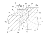
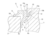
- FIG. 13 shows an application example 4.
- This application example 4 corresponds to the fifth embodiment shown in FIG. 6 and has the same structure except that the annular protrusion 16 and the seal sliding side inclined portion 16a are not provided.
- the effect is also substantially the same as in the fifth embodiment, and the description is omitted.
- the base 6 is not brought into contact with the inner side surface 15 on the axially inner side at the bottom, and the groove bottom 12a and the seal base 6 at the bottom are brought into contact as shown in FIG. 4 showing the third embodiment.
- the base 6 may not be brought into contact with the groove bottom surface 12a, but the inner surface 15 on the inner side in the axial direction at the bottom and the seal base 6 may be brought into contact as shown in FIG. 5 showing the fourth embodiment.
- the friction coefficient between the bottom and the base 6 of the seal member 5 is smaller than in the case of FIG. 13, the base 6 of the seal member 5 is stably fixed and the grease leakage from the annular groove 12 is suppressed. Can be strengthened.
- seal structures and the slewing bearings of the slewing bearings of the application examples 1 to 4 can be applied to the wind turbine of the wind power generator and other uses as in the above embodiments.
- Application examples 1 to 4 that do not have the “annular protrusion 16” as a requirement in each embodiment according to the present invention include the following modes.
- a step that is uneven in the axial direction is provided between the inner and outer rings, and includes an elastic seal member that seals the axial end of the inner and outer rings having the step
- the seal member includes a base fixed to a portion protruding from the concave raceway of the convex raceway that is the convex side of the step, and one or more that are in contact with the concave raceway that is the concave side of the step.
- a lip portion, and one of the lip portions includes a main lip that extends in an inclined manner so as to be located on the inner side in the axial direction of the bearing space toward the tip.
- a seal slidable contact surface portion that slidably contacts the main lip of the seal member;
- An annular groove is provided on the peripheral surface of the convex raceway, and a fixing groove is provided on an outer surface in the axial direction at the bottom of the annular groove, and the base portion of the seal member includes the peripheral surface of the convex raceway and the circumferential surface.
- the cross-sectional shape of the inner surface of the base facing the bottom of the annular groove of the convex raceway of the base of the seal member has an intersection angle of 90 degrees or more and 180 degrees or less. The shape was connected by a plurality of lines.
- the main lip has a lip body part connected to a base part, and a lip protrusion part protruding from the lip body part.
- the lip protrusion part is formed from the lip body part. Also reduced the thickness.
- the angle of the line of intersection connecting the axial inner side surface of the main lip and the base inner side surface of the base portion is set to 180 degrees or more and 270 degrees or less.
- the inner side surface on the inner side in the axial direction at the bottom of the annular groove of the convex bearing ring is inclined so as to be positioned on the side away from the bearing space toward the groove bottom side portion.
- a cross-sectional shape was formed.
- the bottom of the annular groove in the convex race and the base of the seal member are brought into contact with each other.
- the seal member is made of nitrile or chloroprene.
- the seal member includes, as one of the lip portions, a sub lip branched from the base portion separately from the main lip and in contact with the end surface of the concave bearing ring.
- the seal member includes, as one of the lip portions, a sub lip branched from the base portion separately from the main lip and in contact with the end surface of the concave bearing ring.
Landscapes
- Engineering & Computer Science (AREA)
- General Engineering & Computer Science (AREA)
- Mechanical Engineering (AREA)
- Rolling Contact Bearings (AREA)
Abstract
La présente invention a trait à une structure de joint destinée à un support de pivotement, laquelle structure de joint comprend un élément de joint (5) qui est doté d'une partie de base (6) et de parties de lèvre (9), l'une des parties de lèvre (9) incluant une nervure principale (7) qui s'étend suivant une inclinaison. Une partie en saillie annulaire (16) qui fait saillie de façon radiale est prévue de manière à être plus proche de la partie d'extrémité qu'une partie de surface de contact coulissante de joint (2c) sur la surface périphérique d'une bague de roulement côté évidement (2), et une partie inclinée côté coulissant de joint (16a) qui est inclinée vers la pointe en saillie de manière à être positionnée sur la partie extérieure dans la direction axiale est prévue sur la surface intérieure de la partie en saillie annulaire (16) dans la direction radiale. Dans une bague de roulement côté saillie (1), une partie inclinée côté ancrage de joint (13a) qui est inclinée vers une partie côté inférieur de rainure de manière à être positionnée sur la partie extérieure dans la direction axiale est prévue sur la surface intérieure d'une rainure d'ancrage (13) sur la surface côté rainure de la surface périphérique de la partie de base (6).
Applications Claiming Priority (4)
| Application Number | Priority Date | Filing Date | Title |
|---|---|---|---|
| JP2011-060266 | 2011-03-18 | ||
| JP2011060266A JP5606972B2 (ja) | 2011-03-18 | 2011-03-18 | 旋回軸受のシール構造および旋回軸受 |
| JP2012008553A JP5901977B2 (ja) | 2012-01-19 | 2012-01-19 | 旋回軸受 |
| JP2012-008553 | 2012-01-19 |
Publications (1)
| Publication Number | Publication Date |
|---|---|
| WO2012128103A1 true WO2012128103A1 (fr) | 2012-09-27 |
Family
ID=46879256
Family Applications (1)
| Application Number | Title | Priority Date | Filing Date |
|---|---|---|---|
| PCT/JP2012/056278 Ceased WO2012128103A1 (fr) | 2011-03-18 | 2012-03-12 | Structure de joint destinée à un support de pivotement, et support de pivotement |
Country Status (1)
| Country | Link |
|---|---|
| WO (1) | WO2012128103A1 (fr) |
Cited By (5)
| Publication number | Priority date | Publication date | Assignee | Title |
|---|---|---|---|---|
| US20150098669A1 (en) * | 2013-09-27 | 2015-04-09 | Aktiebolaget Skf | Rotative Assembly, Method For Dismounting A Sealing Element And Extraction Tool For Dismounting A Sealing Element |
| WO2017091071A1 (fr) * | 2015-11-27 | 2017-06-01 | Itrec B.V. | Palier à éléments de roulement hermétiquement scellés |
| CN112360881A (zh) * | 2020-10-14 | 2021-02-12 | 宁波万丰轴承有限公司 | 一种深沟球轴承 |
| CN118640228A (zh) * | 2024-07-03 | 2024-09-13 | 瓦房店轴承集团国家轴承工程技术研究中心有限公司 | 风电偏变轴承密封结构 |
| WO2025252300A1 (fr) * | 2024-06-04 | 2025-12-11 | Abb Schweiz Ag | Agencement d'étanchéité et robot industriel |
Citations (5)
| Publication number | Priority date | Publication date | Assignee | Title |
|---|---|---|---|---|
| JPS5438748U (fr) * | 1977-08-23 | 1979-03-14 | ||
| JPH07269576A (ja) * | 1994-03-30 | 1995-10-17 | Shin Caterpillar Mitsubishi Ltd | 旋回軸受のシール構造 |
| JPH10213143A (ja) * | 1997-01-27 | 1998-08-11 | Shin Caterpillar Mitsubishi Ltd | 旋回軸受 |
| JP2005308091A (ja) * | 2004-04-21 | 2005-11-04 | Hitachi Constr Mach Co Ltd | 旋回軸受のシール装置 |
| JP2008215560A (ja) * | 2007-03-07 | 2008-09-18 | Komatsu Ltd | 旋回軸受装置 |
-
2012
- 2012-03-12 WO PCT/JP2012/056278 patent/WO2012128103A1/fr not_active Ceased
Patent Citations (5)
| Publication number | Priority date | Publication date | Assignee | Title |
|---|---|---|---|---|
| JPS5438748U (fr) * | 1977-08-23 | 1979-03-14 | ||
| JPH07269576A (ja) * | 1994-03-30 | 1995-10-17 | Shin Caterpillar Mitsubishi Ltd | 旋回軸受のシール構造 |
| JPH10213143A (ja) * | 1997-01-27 | 1998-08-11 | Shin Caterpillar Mitsubishi Ltd | 旋回軸受 |
| JP2005308091A (ja) * | 2004-04-21 | 2005-11-04 | Hitachi Constr Mach Co Ltd | 旋回軸受のシール装置 |
| JP2008215560A (ja) * | 2007-03-07 | 2008-09-18 | Komatsu Ltd | 旋回軸受装置 |
Cited By (6)
| Publication number | Priority date | Publication date | Assignee | Title |
|---|---|---|---|---|
| US20150098669A1 (en) * | 2013-09-27 | 2015-04-09 | Aktiebolaget Skf | Rotative Assembly, Method For Dismounting A Sealing Element And Extraction Tool For Dismounting A Sealing Element |
| US9541136B2 (en) * | 2013-09-27 | 2017-01-10 | Aktiebolaget Skf | Rotative assembly, method for dismounting a sealing element and extraction tool for dismounting a sealing element |
| WO2017091071A1 (fr) * | 2015-11-27 | 2017-06-01 | Itrec B.V. | Palier à éléments de roulement hermétiquement scellés |
| CN112360881A (zh) * | 2020-10-14 | 2021-02-12 | 宁波万丰轴承有限公司 | 一种深沟球轴承 |
| WO2025252300A1 (fr) * | 2024-06-04 | 2025-12-11 | Abb Schweiz Ag | Agencement d'étanchéité et robot industriel |
| CN118640228A (zh) * | 2024-07-03 | 2024-09-13 | 瓦房店轴承集团国家轴承工程技术研究中心有限公司 | 风电偏变轴承密封结构 |
Similar Documents
| Publication | Publication Date | Title |
|---|---|---|
| JP5606972B2 (ja) | 旋回軸受のシール構造および旋回軸受 | |
| US7572061B2 (en) | Locating bearing assembly for wind turbine gearbox shaft | |
| JP5546638B2 (ja) | 遊星歯車機構、及び風力発電装置 | |
| US20120051915A1 (en) | Planetary gear train with improved bearing structure and manufacture method of the same | |
| EP2881631B1 (fr) | Dispositif d'étanchéité | |
| WO2017065238A1 (fr) | Structure de joint d'étanchéité de palier pivotant | |
| JPWO2010007677A1 (ja) | 軸受構造及び風力発電装置 | |
| JP2012112488A (ja) | 旋回軸受のシール構造および旋回軸受 | |
| KR20140020899A (ko) | 특히 풍력 터빈에 사용되는 각-접촉식 롤러 베어링 | |
| EP2899413A1 (fr) | Palier de production d'énergie éolienne/marémotrice | |
| CN203477060U (zh) | 一种专用密封四点接触球轴承 | |
| WO2012128103A1 (fr) | Structure de joint destinée à un support de pivotement, et support de pivotement | |
| JP2009097525A (ja) | 保持器付き転がり軸受 | |
| CA2787163A1 (fr) | Ensemble roulement a rouleaux coniques a deux rangees et turbine eolienne | |
| WO2011013551A1 (fr) | Structure de joint d'un palier d'orientation et dispositif de support d'orientation | |
| JP5868643B2 (ja) | 等速自在継手 | |
| JP2011208662A (ja) | 転がり軸受 | |
| JP5235392B2 (ja) | 複列アンギュラ玉軸受 | |
| US20160032899A1 (en) | One-way clutch for wind power generation device, and wind power generation device | |
| CN209892613U (zh) | 一种组合托架轴承 | |
| JP2016211601A (ja) | 旋回軸受のシール構造および旋回軸受 | |
| JP5901977B2 (ja) | 旋回軸受 | |
| JP2019060465A (ja) | 旋回軸受のシール構造および旋回軸受 | |
| JP2017008990A (ja) | 旋回軸受のシール構造および旋回軸受 | |
| CN101858389A (zh) | 一种双曲面齿联轴器 |
Legal Events
| Date | Code | Title | Description |
|---|---|---|---|
| 121 | Ep: the epo has been informed by wipo that ep was designated in this application |
Ref document number: 12761050 Country of ref document: EP Kind code of ref document: A1 |
|
| NENP | Non-entry into the national phase |
Ref country code: DE |
|
| 122 | Ep: pct application non-entry in european phase |
Ref document number: 12761050 Country of ref document: EP Kind code of ref document: A1 |