WO2012128123A2 - 自動巻線機、空芯コイル及びその巻線方法 - Google Patents
自動巻線機、空芯コイル及びその巻線方法 Download PDFInfo
- Publication number
- WO2012128123A2 WO2012128123A2 PCT/JP2012/056410 JP2012056410W WO2012128123A2 WO 2012128123 A2 WO2012128123 A2 WO 2012128123A2 JP 2012056410 W JP2012056410 W JP 2012056410W WO 2012128123 A2 WO2012128123 A2 WO 2012128123A2
- Authority
- WO
- WIPO (PCT)
- Prior art keywords
- core
- winding
- unit
- coil
- air
- Prior art date
- Legal status (The legal status is an assumption and is not a legal conclusion. Google has not performed a legal analysis and makes no representation as to the accuracy of the status listed.)
- Ceased
Links
Images


Classifications
-
- H—ELECTRICITY
- H01—ELECTRIC ELEMENTS
- H01F—MAGNETS; INDUCTANCES; TRANSFORMERS; SELECTION OF MATERIALS FOR THEIR MAGNETIC PROPERTIES
- H01F27/00—Details of transformers or inductances, in general
- H01F27/28—Coils; Windings; Conductive connections
- H01F27/2823—Wires
-
- H—ELECTRICITY
- H01—ELECTRIC ELEMENTS
- H01F—MAGNETS; INDUCTANCES; TRANSFORMERS; SELECTION OF MATERIALS FOR THEIR MAGNETIC PROPERTIES
- H01F27/00—Details of transformers or inductances, in general
- H01F27/28—Coils; Windings; Conductive connections
-
- H—ELECTRICITY
- H01—ELECTRIC ELEMENTS
- H01F—MAGNETS; INDUCTANCES; TRANSFORMERS; SELECTION OF MATERIALS FOR THEIR MAGNETIC PROPERTIES
- H01F5/00—Coils
-
- B—PERFORMING OPERATIONS; TRANSPORTING
- B21—MECHANICAL METAL-WORKING WITHOUT ESSENTIALLY REMOVING MATERIAL; PUNCHING METAL
- B21F—WORKING OR PROCESSING OF METAL WIRE
- B21F3/00—Coiling wire into particular forms
- B21F3/02—Coiling wire into particular forms helically
- B21F3/04—Coiling wire into particular forms helically externally on a mandrel or the like
-
- H—ELECTRICITY
- H01—ELECTRIC ELEMENTS
- H01F—MAGNETS; INDUCTANCES; TRANSFORMERS; SELECTION OF MATERIALS FOR THEIR MAGNETIC PROPERTIES
- H01F41/00—Apparatus or processes specially adapted for manufacturing or assembling magnets, inductances or transformers; Apparatus or processes specially adapted for manufacturing materials characterised by their magnetic properties
- H01F41/02—Apparatus or processes specially adapted for manufacturing or assembling magnets, inductances or transformers; Apparatus or processes specially adapted for manufacturing materials characterised by their magnetic properties for manufacturing cores, coils, or magnets
- H01F41/04—Apparatus or processes specially adapted for manufacturing or assembling magnets, inductances or transformers; Apparatus or processes specially adapted for manufacturing materials characterised by their magnetic properties for manufacturing cores, coils, or magnets for manufacturing coils
- H01F41/06—Coil winding
- H01F41/082—Devices for guiding or positioning the winding material on the former
-
- H—ELECTRICITY
- H01—ELECTRIC ELEMENTS
- H01F—MAGNETS; INDUCTANCES; TRANSFORMERS; SELECTION OF MATERIALS FOR THEIR MAGNETIC PROPERTIES
- H01F41/00—Apparatus or processes specially adapted for manufacturing or assembling magnets, inductances or transformers; Apparatus or processes specially adapted for manufacturing materials characterised by their magnetic properties
- H01F41/02—Apparatus or processes specially adapted for manufacturing or assembling magnets, inductances or transformers; Apparatus or processes specially adapted for manufacturing materials characterised by their magnetic properties for manufacturing cores, coils, or magnets
- H01F41/04—Apparatus or processes specially adapted for manufacturing or assembling magnets, inductances or transformers; Apparatus or processes specially adapted for manufacturing materials characterised by their magnetic properties for manufacturing cores, coils, or magnets for manufacturing coils
- H01F41/06—Coil winding
- H01F41/098—Mandrels; Formers
Definitions
- the present invention relates to an automatic winding machine for producing an air-core coil that can be inserted into a core equipped in a rectifier circuit, a noise prevention circuit, a resonance circuit, etc. in various AC devices.
- the present invention also relates to an air-core coil comprising a plurality of coil layers and a winding method thereof.
- Coil devices installed in AC device rectifier circuits, noise prevention circuits, resonance circuits, etc. are formed by winding a coil around a core.
- Patent Document 1 a method of manufacturing a coil device by inserting an air-core coil wound in advance in a spiral shape into a core having a gap opened in a tangential direction from the gap.
- the automatic winding machine disclosed in Patent Document 1 includes a pair of core members having a substantially rectangular cross section that rotate integrally with a rotation drive mechanism, and rotates while changing the interval between the core members, so that the winding member directly By winding the conducting wire, air core coils having different inner peripheral lengths on the inner peripheral side of the core and outer peripheral lengths on the outer peripheral side of the core are produced.
- Patent Document 2 As a method of producing air core coils having different inner and outer peripheral lengths, a method using a stepped winding jig corresponding to the cavity shape of the air core coil (Patent Document 2), There is known an automatic winding machine that winds a conductive wire around the core member while changing the form of the core member for each winding process (Patent Document 3).
- the conductor wire on the inner peripheral side of the core can be partially overlapped in the radial direction and the conductor wire can be tightly wound.
- an air-core coil (200) in which unit coil portions (23) formed by winding a conducting wire (22) in a spiral shape are repeatedly arranged in the winding axis direction.
- a winding method of such an air core coil (200) as shown in FIG.
- a first unit winding portion (25) having different inner peripheral lengths by winding a conducting wire in a spiral shape
- the second unit winding part (26) and the third unit winding part (27) are continuously formed in the winding axis direction
- a unit coil part comprising the plurality of unit winding parts (25) (26) (27) Are formed continuously in the winding axis direction to produce an intermediate product of an air-core coil, and then the intermediate product is compressed in the winding axis direction, as shown in FIG.
- Patent Document 2 A method for obtaining a finished product of an air-core coil composed of a plurality of coil layers (three layers in the illustrated example) is known (Patent Document 2).
- the starting end of the conducting wire constituting the air-core coil is attached to the rotation drive mechanism side of the winding core member, and the winding is sequentially wound in a direction away from the rotation drive mechanism. For this reason, after an air-core coil is produced, the operation
- the air-core coil produced by the automatic winding machine not only has a different inner peripheral length, but also changes the outer peripheral length according to the inner peripheral length. Accordingly, when the coil is wound around the core, the coil outer peripheral side conductor may not be in close contact with the coil and the sagging may occur.
- the first object of the present invention is to provide an automatic winding machine capable of producing an air-core coil having unit winding portions having different inner peripheral lengths but the same outer peripheral length.
- the bent portions (25c), (26c), and (27c) of the plurality of unit winding portions (25), (26), and (27) that constitute the above-described air-core coil are formed. Since the plurality of bent portions (25c) (26c) (27c) to be formed by the corner portion (30a) have an arc shape with the same radius of curvature, the bent portions of the inner and outer unit winding portions A gap G is generated between them. As a result, there has been a problem that the space factor of the conductive wire in the air-core coil is reduced.
- the first unit winding (25), the second unit winding (26) and the third unit winding are provided at each corner (23c) of the air-core coil.
- the bent portions (25c), (26c) and (27c) of (27) are formed in an arc shape having the same curvature center S and having a radius of curvature that increases by the diameter of the conducting wire from the inner peripheral side toward the outer peripheral side. Can be considered.
- the bent portions of the unit winding portions on the inner peripheral side and the outer peripheral side are in close contact with each other, and the space factor of the conducting wire is increased.
- a second object of the present invention is to provide an air-core coil that can increase the space factor of the conductive wire as compared with the conventional one, and a winding method that can easily manufacture such an air-core coil. It is.
- the automatic winding machine of the present invention is: Unit coil portions formed by spirally winding at least one conducting wire are repeatedly arranged in the winding axis direction, and each unit coil portion is formed from a plurality of unit winding portions having different inner circumferential lengths.
- This is an automatic winding machine for producing an air-core coil in which at least a part of a unit winding with a small inner peripheral length is pushed inside a unit winding with a large inner peripheral length when inserted into a core having a gap.
- a rotation drive mechanism Projecting from the rotational drive mechanism, rotating integrally with the rotational center of the rotational drive mechanism, and having an axis of four core shafts parallel to the rotational center; A first position where the axis of the core axis is a substantially rectangular apex position where the axis of the core axis surrounds the rotation center, and two opposite sides connecting between the core axes are an inner circumference length and an outer circumference length; and A reciprocating mechanism that reciprocally moves the core shaft between a first position and a second position that is the same as the outer peripheral length and a substantially trapezoidal apex position having a long inner peripheral length; At least one presser roller biased in a direction approaching the rotation transition path of the core shaft from the outer peripheral side; A conductor supply mechanism for continuously supplying a conductor between the winding core shaft and the presser roller; Have
- the conductor wire supplied from the conductor supply mechanism is disposed closer to the front side in the rotational direction than the position where the conductor wire shaft first comes into contact with any one of the core shafts, and the conductor wound around the core shaft is provided. It is desirable to provide a pusher member that pushes to the free end side of the core shaft.
- unit coil portions formed by winding at least one conductive wire in a spiral shape are repeatedly arranged in the winding axis direction, Each unit coil portion is formed of a plurality of unit winding portions having different inner peripheral lengths, and at least a part of the unit winding portion having a smaller inner peripheral length is pushed inside the unit winding portion having a larger inner peripheral length.
- each of the plurality of unit winding portions forming each unit coil portion has a polygonal shape having a plurality of corner portions, and each of the plurality of corner portions has a plurality of bent portions obtained by bending the conducting wire to an obtuse angle, and It is comprised from 1 or several connection part which connects adjacent bending parts.
- the plurality of bent portions that overlap each other at the same phase position are arranged on a single straight line extending from the inside to the outside of the unit coil portion.
- the air-core coil is not limited to a coil that does not have a core in the space in the center of the coil as a final product, and a coil in a core that has a core in the space in the center of the coil (coil device) as a final product It is a concept that includes.
- each corner portion a straight line formed by a plurality of unit winding portions and overlapping a plurality of bent portions at the first phase position is formed, and a plurality of unit winding portions are formed by a plurality of unit winding portions.
- a single straight line in which a plurality of bent portions overlapping at two phase positions are arranged intersects at one point inside the unit coil portion.
- the air core coil winding method of the present invention is the air core coil winding method of the present invention described above, and coincides with the number of corners of the polygonal shape around the rotating shaft serving as the winding shaft.
- a plurality of core mechanisms that are rotationally driven around the rotating shaft, and each core mechanism is equipped with a plurality of core pieces that can be driven to reciprocate in a direction crossing the winding shaft,
- the plurality of unit winding portions constituting one unit coil portion are formed by repeating the positions of the plurality of winding core pieces while changing the position in the direction away from the rotation shaft or in the opposite direction.
- the unit winding portion is connected to a plurality of core pieces by a conductive wire that becomes the second unit winding portion.
- the second unit winding portion is formed by winding the conductive wire serving as the second unit winding portion around the outer peripheral surface of the plurality of core pieces while extruding from the outer peripheral surface.
- the coil portion having the unit coil portion composed of the unit winding portions having different inner peripheral lengths can be continuously produced. Can do.
- the coil portion produced by the automatic winding machine of the present invention can form a substantially trapezoidal unit winding portion with a changed inner peripheral length while keeping the outer peripheral length the same as the substantially rectangular unit winding portion,
- the obtained coil part is inserted into a core with a gap, not only can a part of the conducting wire be overlapped on the inner peripheral surface of the core, but the outer peripheral length is the same, so that the outer periphery of the core is denser than before.
- the conductor can be wound around.
- the produced unit winding part is sequentially pushed out to the free end side of the core shaft by the pusher member, so that the automatic winding machine is stopped and the coil part is removed and the conductor is automatically wound again as before.
- the work to attach to the machine can be omitted.
- the air-core coil of the present invention is an ideal structure in which each corner has an arc shape with a plurality of bent portions of a plurality of unit winding portions, and the arc shape is approximated by a polygonal shape (a polygonal line). Therefore, the gap between the bent portions at each corner becomes smaller than the conventional one, and the space factor of the conducting wire becomes large.
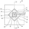
- FIG. 1 is a perspective view showing a main part of an automatic winding machine according to a first embodiment of the present invention.
- FIG. 2 is a perspective view showing a state in which a plurality of core shafts are moved and rotated from the state of FIG. 1 in the automatic winding machine.
- FIG. 3 is a front view showing a main part of the automatic winding machine. 4 is a cross-sectional view taken along line AA in FIG.
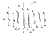
- FIG. 5 is a series of front views showing a winding process using the automatic winding machine.
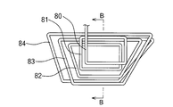
- FIG. 6 is a front view of an air-core coil manufactured by the automatic winding machine.
- FIG. 7 is a sectional view taken along line BB in FIG.
- FIG. 8A to 8C are cross-sectional views taken along lines aa, bb, and cc of FIG. 7, respectively.
- FIG. 9 is an explanatory view showing a state where an air-core coil is inserted into the core.
- FIG. 10 is an enlarged view of a main part of the coil device.
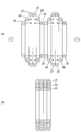
- FIG. 11 is a front view of an air-core coil according to the second embodiment of the present invention.
- FIG. 12 is a front view showing the main structure of an automatic winding machine for manufacturing an air core coil according to the second embodiment of the present invention and the operation of a plurality of core pieces.
- FIG. 13 is a diagram showing gaps formed between bent portions of a plurality of unit winding portions in a conventional air-core coil.
- FIG. 14 is a diagram showing a close state in an ideal structure in which bent portions of a plurality of unit winding portions are formed in a plurality of arcs having different radii of curvature.
- FIG. 15 is a perspective view of a conventional air-core coil.
- FIG. 16 is a diagram illustrating a compression process of the air-core coil.
- FIG. 1 and 2 a first enlarged perspective view showing a main part of an automatic winding machine (10) which is an embodiment of the present invention
- FIG. 3 an automatic winding machine (10)
- FIG. 4 is a cross-sectional view taken along line AA in FIG.
- the automatic winding machine (10) has a central base shaft (20) that rotates counterclockwise as shown by the arrow in FIG. 1 by a rotational drive mechanism (not shown) such as a motor.
- Four core shafts (31), (32), (33), and (34) that rotate integrally with the central base shaft (20) are arranged around (20).
- the core shafts (31), (32), (33), and (34) are arranged so as to be rotatable integrally with the central base shaft (20), and slide blocks (41) that slide toward and away from the central base shaft (20). ) (42) (43) (44). More specifically, the core shaft (31) (32) (33) (34) is attached to the corner of the slide block (41) (42) (43) (44) on the central base shaft (20) side. The tip protrudes from the slide blocks (41) (42) (43) (44).
- the core shafts (31), (32), (33), and (34) can be prisms with the central base shaft (20) side cut out, and as will be described later, slide blocks (41), (42), (43) ( The core shafts (31), (32), (33) and (34) can be moved toward and away from each other by sliding the shaft 44 in parallel with the central base shaft (20).
- the tip of the core shaft (31) (32) (33) (34) is slightly smaller than the diameter of the conductor (70) from the tip surface (45) of the slide block (41) (42) (43) (44). It protrudes to become longer.
- the projecting length of the core shafts (31), (32), (33) and (34) is preferably 1 to 3 mm longer than the diameter of the conductor (70), and specifically the projecting length is 2 to 2 mm. It is desirable to be about 5 mm.
- presser rollers (51) (52) (53) are arranged on the outer periphery of the rotation transition path of the core shafts (31) (32) (33) (34).
- three presser rollers (51), (52) and (53) are provided every 90 ° on the upper and lower sides and on the left side of the central base shaft (20). It is urged from a non-rotating casing (not shown) by a biasing means such as a spring in a direction approaching the rotation transition path of the core shafts (31) (32) (33) (34).
- the presser rollers (51) (52) (53) are thin cylindrical presser body portions on the slide blocks (41) (42) (43) (44) side. (55) and a disc-shaped presser plate (56) formed on the front side of the presser body part (55) and having a diameter larger than that of the presser body part (55). It is desirable that the width of the presser body portion (55) is substantially the same as the protruding length of the core shafts (31), (32), (33), and (34).
- the presser body portion (55) and the presser plate (56) can be integrally formed, and the presser body portion (55) and the presser plate (56) are provided with a shaft hole (57) penetrating through the center.
- An urging means for urging the shaft hole (57) in a direction approaching the rotation transition path is connected to the shaft hole (57).
- a lead wire (70) forming an air-core coil is supplied from the upstream side in the rotation direction of the core shaft (31).
- the conducting wire (70) can be supplied by a conducting wire supply mechanism (not shown), and the conducting wire supply mechanism passes the plurality of guide rollers (not shown) through the plurality of guide rollers (not shown), and the presser roller whose tip is on the upper side.
- a configuration in which a cylindrical guide (76) that opens between the shaft 51 (51) and the rotation transition path of the core shafts (31), (32), (33), and (34) is sequentially supplied can be exemplified.
- the lead wire (70) wound around the core shaft (31) (32) (33) (34) is connected to the core shaft (31 ) (32), (33), and a pusher member (77) pushed out to the free end side of (34).
- the pusher member (77) is disposed in a non-rotating casing (not shown) of the automatic winding machine (10), and approaches the rotation transition path of the core shafts (31) (32) (33) (34). Deployed.
- the urging means or the like urges the core shafts (31), (32), (33), and (34) to approach the rotation transition path. It is desirable to keep it.
- a winding auxiliary member (21) into which the unit winding portions pushed out by the pusher member (77) are sequentially inserted is detachably fitted to the central base shaft (20).
- the winding auxiliary member (21) can be exemplified by a resin, and the cross-sectional shape can be exemplified by a substantially cross-sectional rectangular shape to which the unit winding portion to be formed fits with a margin.
- the winding auxiliary member (21) can be about 30 cm in length.
- the automatic winding machine (10) configured as described above has a reciprocating mechanism constituted by a cam mechanism or the like, and the rotating slide blocks (41) (42) (43) (44) are wound around the core shaft (31) ( 32) It is slidable in the approach and separation directions within the plane orthogonal to the axis of (33) and (34). More specifically, as shown in FIG. 5 (a), the reciprocating mechanism has a state in which the core shafts (31), (32), (33), and (34) are positioned at the vertices of a rectangle, and FIG. ), While the core shaft (31) (32) (33) (34) is located at the apex of the trapezoid, the slide block (41) (42) (43) (44) is made slidable.
- the lead wire supply mechanism (not shown) is manually operated by the user with the core shafts (31), (32), (33) and (34) positioned in advance at the vertices of the rectangle.
- the lead wire (70) is pulled out from the lead wire, and the tip of the lead wire (70) is bent into a U-shape and hooked on the outer periphery of the core shaft (31) (32) (33) (34).
- the lead wire (70) is connected to the leading end surfaces (31), (32), (33), and (34) of the core shafts (41), (42), (43), and (44). 45) and the presser body (55) and presser plate (56) of the presser rollers (51), (52) and (53) are surrounded by the presser rollers (51), (52) and (53) and will not fall off.
- the winding core shaft (31) (32) (33) (34) rotates about 270 ° from the beginning of winding of the conducting wire (70), as shown in FIG. 5 (b), the conducting wire (70) becomes the pusher member (77). At this time, it is pushed out to the free end side of the core shafts (31), (32), (33) and (34) and inserted into the winding auxiliary member (21) (see FIG. 4).
- the conductive wire (70) becomes a substantially rectangular unit winding portion (80) (81) that is rotated twice.
- the core shaft (31) that matches the vertex of one of the long sides of the rectangle is set as the central base axis.
- the core shafts (31), (32), (33) and (34) are rotated while being moved away from (20).
- the core shafts (31), (32), (33), and (34) are moved at positions that oppose the guide (76) that supplies the conducting wire (70). The reason is that if the core shaft around which the conducting wire (70) is wound is moved, the conducting wire (70) may be pulled and cut.
- the lead wire (70) is also moved by the pusher member (77) for the core shaft (34) on the other long side as shown in FIG. 5 (d). Extruded and moved away from the central base axis (20). Similarly, as shown in FIG. 5 (e), the core shafts (31), (32), (33), and (34) at the apexes of the long sides of the other side of the rectangle. , While being rotated, is moved in a direction away from the central base shaft (20), although the distance is shorter than the core shaft (31) (34). Note that the position of the core shaft (31) (32) (33) (34) at this time is referred to as an intermediate position.
- the core shaft (31) (32) (33) (34) is further away from the central base shaft (20) from the intermediate position.
- the core shaft (31) (32) (33) (34) is moved to the position that is the apex of the substantially trapezoidal shape while moving the core shaft (31) (32) (33) (34).
- the lead wire (70) forms a substantially trapezoidal unit winding portion (83) (84) having an outer peripheral length and an inner peripheral length longer than the intermediate position. .
- the lead wire (70) has a substantially trapezoidal two-turn unit winding portion (83) (84). Become.
- the core shafts (31), (32), (33), and (34) are rotated while sequentially returning to the intermediate position, and the core shafts (31), (32), (33), (34) are further rotated as described above.
- a unit coil part (79) in which (80) (81) (82) (83) (84) is continuous is wound around the winding auxiliary member (21) to form an air-core coil.
- the automatic winding machine (10) is once stopped, and the lead wire (70) can be cut on the winding auxiliary member (21) to obtain an air core coil. .
- the air core coil is continuously produced by operating the automatic winding machine (10) again.
- the air-core coil has three unit winding portions (80) (82) having different inner peripheral lengths located on the inner peripheral side of the core (87) and different outer peripheral lengths located on the outer peripheral side of the core (87). ) (83), the substantially rectangular unit winding part (80) (81) has two rounds, the substantially trapezoidal unit winding part (83) (84) has two rounds, and the unit winding part is formed at an intermediate position. (82) has a shape that is wound by one turn between (81) and (83) and between (82) and (80) of both unit winding portions.
- the produced air-core coil is inserted from the gap (86) into the core (87) having the gap (86) opened in the connecting direction as shown in FIG.
- the air-core coil is formed of unit winding portions (80), (82) and (83) having different inner peripheral lengths, as shown in FIG. 10, the unit winding portions (83) and (84) having a long inner peripheral length.
- the unit winding portions (83) and (84) having a long inner peripheral length.
- FIG. 11 shows an air-core coil (2) according to the present invention.
- the air-core coil (2) according to the present invention has basically the same winding structure as that of the air-core coil (200) shown in FIG. 15, and a single conductor (22) is wound as shown in FIG.
- a unit coil portion (23) formed by spirally winding along a plane orthogonal to the axis is formed continuously in the direction of the winding axis, thereby forming an air-core coil composed of three coil layers. ing.
- each unit coil portion (23) has a substantially rectangular shape having four corner portions (23a) (23a) (23a) (23a) as a whole.
- the first unit winding portion (25) is pushed into the second unit winding portion (26) by the substantially entire length thereof, and the second unit winding portion (26) has a substantially entire length of the third unit. It is pushed inside the winding part (27).
- the first unit winding portion (25) has two bending portions (25a) (25a), and the second unit winding portion (26) has two bending portions.
- the third unit winding portion (27) has two bent portions (27a) and (27a), and the bent angle of each bent portion is set to 45 degrees.
- each corner portion (23a) the two bent portions (25a) and (25a) of the first unit winding portion (25) are connected to each other by a linear connecting portion (25b), and the second unit winding portion (26) is connected.
- the two bent portions (26a) and (26a) are connected to each other by a linear connecting portion (26b), and the two bent portions (27a) and (27a) of the third unit winding portion (27) are linear connecting portions ( They are connected to each other by 27b).
- each corner portion (23a) the lead wire of the first unit winding portion (25) and the lead wire of the second unit winding portion (26) are in contact with each other over substantially the entire length, and the second unit winding portion.
- the lead wire (26) and the lead wire of the third unit winding portion (27) are in contact with each other over substantially the entire length.
- the corner portion (23a) of the air-core coil (2) according to the present invention includes the first unit winding portion (25), the second unit winding portion (26), and the third unit winding portion (shown in FIG. This corresponds to an approximation of the arc shape of the three bent portions (25c), (26c) and (27c) of (27) by two or more polygonal shapes (polygonal lines).
- the air-core coil (2) according to the present invention has an intermediate configuration between the conventional air-core coil (200) shown in FIG. 13 and the ideal air-core coil shown in FIG. The gap between the bends at the corners is smaller than in the prior art.
- the air-core coil (2) according to the present invention has a larger space factor than the conventional air-core coil (200) shown in FIG.
- the air-core coil (2) according to the present invention can be easily manufactured by using a modification of the automatic winding machine (10) used in the first embodiment shown in FIGS. .
- the air-core coil produced using the automatic winding machine (10) of the first embodiment has a first unit winding part (25), a second unit winding part (26) and a third unit as shown in FIG. A gap G is generated between the bent portions of the winding portion (27).
- the automatic winding machine (1) shown in FIG. instead of the automatic winding machine (10) having the core shafts (31), (32), (33) and (34) shown in FIG. 1, the automatic winding machine (1) shown in FIG. ).
- the automatic winding machine (1) is rotationally driven in a counterclockwise direction as indicated by an arrow in the drawing by a motor (not shown), and has four core mechanisms (11) ( 12) (13) (14) are deployed.
- the first core mechanism (11) is a first core piece that is reciprocated along a straight line A1 extending outward from one point S1 on the center base shaft (20) side. (61) and a second core piece (62) reciprocally driven along a straight line A2 extending outward from the one point S1, and the first core piece (61) and the second core piece (62) are The function corresponding to the first core shaft (31) of the first embodiment is exhibited.
- the second core mechanism (12) includes a first core piece (63) reciprocatingly driven along a straight line A3 extending outward from one point S2 on the central base shaft (20) side, and outward from the one point S2.
- a second core piece (64) reciprocally driven along the extending straight line A4, and the first core piece (63) and the second core piece (64) are the second core shaft of the first embodiment ( Exhibit the function corresponding to 32).
- the third core mechanism (13) includes a first core piece (65) reciprocally driven along a straight line A5 extending outward from one point S3 on the central base shaft (20) side, and outward from the one point S3.
- a second core piece (66) that is reciprocally driven along the extending straight line A6, and the first core piece (65) and the second core piece (66) are the third core shaft of the first embodiment ( Exhibits the function corresponding to 33).
- the fourth core mechanism (14) includes a first core piece (67) reciprocally driven along a straight line A7 extending outward from one point S4 on the central base shaft (20) side, and outward from the one point S3.
- a second core piece (68) reciprocally driven along the extending straight line A8, and the first core piece (67) and the second core piece (68) are the fourth core shaft of the first embodiment ( Exhibit functions corresponding to 34).
- the reciprocating drive of the above eight core pieces (61) to (68) can be performed, for example, by equipping each core mechanism with a reciprocating drive mechanism such as a solenoid for each core piece.
- Each of the eight core pieces (61) to (68) has a chevron with a vertex angle of 135 degrees on the surface on which the conductive wire (22) is wound. Therefore, when the conducting wire (22) is wound around two pairs of winding core pieces, two bends of the first unit winding portion (25) to form each corner of the air core coil (2) shown in FIG. Parts (25a) (25a), two bent parts (26a) (26a) of the second unit winding part (26), and two bent parts (27a) (27a) of the third unit winding part (27), Will be formed.
- the loop shape defined by the surfaces of the eight core pieces (61) to (68) is the loop of each unit winding part (25) (26) (27) of the air core coil (2) shown in FIG. It corresponds to the shape.
- the other configuration of the automatic winding machine (1) of the air-core coil (2) according to the second embodiment is the same as that of the automatic winding machine (10) of the first embodiment shown in FIGS. It is.
- the conducting wire (22) of the unit winding part is replaced by the conducting wire (22) serving as the second unit winding part. While extruding from the outer peripheral surface of the eight core pieces (61) to (68), the conductor (22) as the second unit winding portion is wound around the outer peripheral surface of the eight core pieces (61) to (68). A second unit winding is formed.
- an air core coil intermediate product shown in FIG. 11 is obtained.
- the intermediate product is compressed in the direction of the winding axis so that the second unit winding portion 26 is pushed inside the third unit winding portion 27 and the second unit winding portion 26 is pushed.
- the first unit winding part (25) is pushed into the inside of the two unit winding part (26) to obtain a completed product of the air-core coil (2) shown in FIG.
- the air-core coil (2) obtained in this way has a conductor of the first unit winding (25) and a conductor of the second unit winding (26) at each corner (23a).
- the conductors of the second unit winding part (26) and the conductors of the third unit winding part (27) are in contact with each other over substantially the entire length. Accordingly, the air-core coil (2) has a larger space factor than the conventional air-core coil (200) shown in FIG.
- each part structure of this invention is not restricted to the said embodiment, A various deformation
- the type of unit winding part and the number of windings are of course not limited to the above.
- the unit winding portion can be set in various ways such as two types of the above-described substantially rectangular shape and substantially trapezoidal shape, and the number of windings can be one round, two rounds, and three rounds.
- the number of bending portions of each unit winding portion at each corner of the air-core coil is not limited to two, and may be three or more.
- the conducting wire (22) is not limited to a round wire with a circular cross section, but may be a square wire with a rectangular cross section.
Landscapes
- Engineering & Computer Science (AREA)
- Power Engineering (AREA)
- Manufacturing & Machinery (AREA)
- Mechanical Engineering (AREA)
- Manufacture Of Motors, Generators (AREA)
- Coil Winding Methods And Apparatuses (AREA)
- Wire Processing (AREA)
- Storage Of Web-Like Or Filamentary Materials (AREA)
- Coils Of Transformers For General Uses (AREA)
Abstract
Description
このような空芯コイル(200)の巻線方法として、図16(a)の如く、導線を渦巻き状に巻回することにより、互いに異なる内周長を有する第1単位巻部(25)、第2単位巻部(26)及び第3単位巻部(27)を、巻き軸方向に連続して形成すると共に、これら複数の単位巻部(25)(26)(27)からなる単位コイル部を、巻き軸方向に連続して形成して、空芯コイルの中間製品を作製した後、該中間製品を巻き軸方向に圧縮して、図16(b)の如く、第3単位巻部(27)の内側に第2単位巻部(26)の少なくとも一部を押し込むと共に、該第2単位巻部(26)の内側に第1単位巻部(25)の少なくとも一部を押し込むことにより、複数のコイル層(図示する例では3層)からなる空芯コイルの完成品を得る方法が知られている(特許文献2)。
これによって、空芯コイルにおける導線の占積率が低下する問題があった。
これによって、内周側と外周側の単位巻部の屈曲部どうしが密接し、導線の占積率が増大する。
少なくとも1本の導線を渦巻き状に巻回して形成される単位コイル部が、巻き軸方向に繰り返し並んでおり、各単位コイル部は、互いに内周長の異なる複数の単位巻部から形成され、ギャップを有するコアに挿入したときに、内周長の大きな単位巻部の内側に内周長の小さな単位巻部の少なくとも一部が押し込まれる空芯コイルを作製するための自動巻線機であって、
回転駆動機構と、
該回転駆動機構から突設され、回転駆動機構の回転中心と一体に回転し、軸心が前記回転中心と平行な4本の巻芯軸を有し、
巻芯軸を、該巻芯軸の軸心が前記回転中心を囲む略矩形の頂点位置となり、巻芯軸間を結ぶ対向する2辺が内周長及び外周長となる第1位置と、該第1位置と外周長は同じで、内周長の長い略台形の頂点位置となる第2位置と、の間で巻芯軸を往復移動させる往復移動機構と、
外周側から巻芯軸の回転移行路に接近する方向に付勢された少なくとも1つの押えローラと、
巻芯軸と押えローラとの間に導線を連続供給する導線供給機構と、
を有する。
ここで、各単位コイル部を形成する複数の単位巻部はそれぞれ、複数の角部を有する多角形状を呈し、該複数の角部はそれぞれ、導線を鈍角に屈曲させた複数の屈曲部と、隣接する屈曲部どうしを繋ぐ1又は複数の連絡部とから構成される。
各単位コイルを構成する複数の単位巻部の角部において、同じ位相位置で互いに重なる複数の屈曲部は、単位コイル部の内側から外側へ向けて延びる1本の直線上に並んでいる。
各巻芯機構の複数の巻芯片を所定位置に設定する第1工程と、
前記複数の巻芯片が所定位置に設定された状態で、前記複数の巻芯機構を回転させることにより、これらの巻芯機構を構成する複数の巻芯片の周囲に導線を巻き付ける第2工程
とを、複数の巻芯片の位置を前記回転軸から離間する方向若しくはその逆方向へ変更しつつ繰り返すことにより、1つの単位コイル部を構成する複数の単位巻部を形成する。
第1実施例
図1及び図2は、本発明の第1の実施例である自動巻線機(10)の要部を拡大して示す斜視図、図3は、自動巻線機(10)の平面図、図4は、図3の線A-Aに沿う断面図である。
自動巻線機(10)は、モータ等の回転駆動機構(図示せず)により図1中矢印方向で示すように反時計回りに回転する中心基軸(20)を有しており、該中心基軸(20)の周囲には、中心基軸(20)と一体に回転する4本の巻芯軸(31)(32)(33)(34)が配備されている。
より具体的には、巻芯軸(31)(32)(33)(34)は、スライドブロック(41)(42)(43)(44)の中心基軸(20)側の角に取り付けられており、先端がスライドブロック(41)(42)(43)(44)から臨出している。
巻芯軸(31)(32)(33)(34)は、中心基軸(20)側が切り欠かれた角柱とすることができ、後述するとおり、スライドブロック(41)(42)(43)(44)を中心基軸(20)に対して平行にスライドさせることにより、巻芯軸(31)(32)(33)(34)は、互いに接近、離間可能となっている。
より具体的には、往復移動機構は、図5(a)に示すように、巻芯軸(31)(32)(33)(34)が長方形の頂点に位置する状態と、図5(f)に示すように、巻芯軸(31)(32)(33)(34)が台形の頂点に位置する状態との間を中心基軸(20)周りに一体回転させつつ、スライドブロック(41)(42)(43)(44)をスライド可能としている。
まず、図5(a)に示すように、予め巻芯軸(31)(32)(33)(34)が長方形の頂点に位置する状態で、ユーザにより手動で導線供給機構(図示せず)から導線(70)を引き出し、導線(70)の先端をコ字状に曲げて、巻芯軸(31)(32)(33)(34)の外周に引っ掛ける。
次に、回転駆動機構を作動させつつ、往復移動機構を作動させることにより、図5(c)に示すように、長方形の一方の長辺の頂点に合った巻芯軸(31)を中心基軸(20)から遠ざかる方向に移動させながら、巻芯軸(31)(32)(33)(34)を回転させる。
なお、巻芯軸(31)(32)(33)(34)は、導線(70)を供給するガイド(76)に対向する位置にあるものを移動させる。この理由は、既に導線(70)が巻回されている巻芯軸を移動させると、導線(70)が引っ張られて切断等することがあるからである。
次に、本発明の第2の実施例である自動巻線機(1)につき、図面に沿って具体的に説明する。図11は、本発明に係る空芯コイル(2)を示している。
本発明に係る空芯コイル(2)は、図15に示す空芯コイル(200)と基本的に同一の巻線構造を有しており、図15の如く1本の導線(22)を巻き軸と直交する面に沿って渦巻き状に巻回して形成される単位コイル部(23)が、巻き軸方向に連続して形成され、これによって3層のコイル層からなる空芯コイルが構成されている。
この結果、本発明に係る空芯コイル(2)は、図15に示す従来の空芯コイル(200)よりも導線の占積率が大きくなる。
該自動巻線機(1)は、図示省略するモータによって図中の矢印で示すように反時計方向に回転駆動されるものであって、その四隅には、4つの巻芯機構(11)(12)(13)(14)が配備されている。
8つの巻芯片(61)~(68)の各表面に導線(22)が順次巻き付けられることによって、第2単位巻部(26)の8つの屈曲部(26a)~(26a)が順次形成され、各屈曲部の屈曲角度が45度に規定されることになる。
8つの巻芯片(61)~(68)の各表面に導線(22)が順次巻き付けられることによって、第2単位巻部(26)の8つの屈曲部(26a)~(26a)が順次形成され、各屈曲部の屈曲角度が45度に規定されることになる。
8つの巻芯片(61)~(68)の各表面に導線(22)が順次巻き付けられることによって、第3単位巻部(27)の8つの屈曲部(27a)~(27a)が順次形成され、各屈曲部の屈曲角度が45度に規定されることになる。
従って、該空芯コイル(2)は、図15に示す従来の空芯コイル(200)よりも導線の占積率が大きくなる。
また、導線(22)は断面円形の丸線に限らず、断面矩形の角線であってもよい。
(2)(60) 空芯コイル
(11)-(14) 巻芯機構
(20) 中心基軸
(21) 巻線補助部材
(23) 単位コイル部
(31)-(34) 巻芯軸
(41)-(44) スライドロック
(51)-(53) 押えローラ
(55) 押え胴部
(56) 押え板
(57) 軸孔
(61)(63)(65)(67) 第1巻芯片
(62)(64)(66)(68) 第2巻芯片
(70) 導線
(76) ガイド
(77) プッシャー部材
(80)-(84) 単位巻部
Claims (11)
- 少なくとも1本の導線を渦巻き状に巻回して形成される単位コイル部が、巻き軸方向に繰り返し並んでおり、各単位コイル部は、互いに内周長の異なる複数の単位巻部から形成され、ギャップを有するコアに挿入したときに、内周長の大きな単位巻部の内側に内周長の小さな単位巻部の少なくとも一部が押し込まれる空芯コイルを作製するための自動巻線機であって、
回転駆動機構と、
該回転駆動機構から突設され、回転駆動機構の回転中心と一体に回転し、軸心が前記回転中心と平行な4本の巻芯軸を有し、
巻芯軸を、該巻芯軸の軸心が前記回転中心を囲む略矩形の頂点位置となり、巻芯軸間を結ぶ対向する2辺が内周長及び外周長となる第1位置と、該第1位置と外周長は同じで、内周長の長い略台形の頂点位置となる第2位置と、の間で巻芯軸を往復移動させる往復移動機構と、
外周側から巻芯軸の回転移行路に接近する方向に付勢された少なくとも1つの押えローラと、
巻芯軸と押えローラとの間に導線を連続供給する導線供給機構と、
を有することを特徴とする自動巻線機。 - 導線供給機構から供給される導線が何れかの巻芯軸に最初に当接する位置よりも回転方向手前側に近接して配備され、巻芯軸に巻回された導線を巻芯軸の自由端側に押し出すプッシャー部材を具える請求項1に記載の自動巻線機。
- 回転駆動機構の回転中心には、巻芯軸より突出して中心基軸が形成されており、該中心基軸は、断面略矩形の巻線補助部材が着脱可能に嵌められる請求項1又は請求項2に記載の自動巻線機。
- 少なくとも1本の導線を渦巻き状に巻回して形成される単位コイル部が、巻き軸方向に繰り返し並んでおり、各単位コイル部は、互いに内周長の異なる複数の単位巻部から形成され、内周長の大きな単位巻部の内側に内周長の小さな単位巻部の少なくとも一部が押し込まれている空芯コイルにおいて、
各単位コイル部を形成する複数の単位巻部はそれぞれ、複数の角部を有する多角形状を呈し、該複数の角部はそれぞれ、導線を鈍角に屈曲させた複数の屈曲部と、隣接する屈曲部どうしを繋ぐ1又は複数の連絡部とから構成され、
各単位コイルを構成する複数の単位巻部の角部において、同じ位相位置で互いに重なる複数の屈曲部は、単位コイル部の内側から外側へ向けて延びる1本の直線上に並んでいることを特徴とする空芯コイル。 - 各角部において、複数の単位巻部に形成されて第1の位相位置で重なる複数の屈曲部が並んでいる1本の直線と、複数の単位巻部に形成されて第2の位相位置で重なる複数の屈曲部が並んでいる1本の直線とは、単位コイル部の内側の1点で交わっている請求項4に記載の空芯コイル。
- 各角部において、複数の単位巻部はそれぞれ、前記1点を中心とする円弧を2以上の多角形状によって近似した経路に沿って延びている請求項5に記載の空芯コイル。
- 前記連絡部は、直線状若しくは円弧状に形成される請求項4乃至請求項6の何れかに記載の空芯コイル。
- 少なくとも1本の導線を渦巻き状に巻回して形成される単位コイル部が、巻き軸方向に繰り返し並んでおり、各単位コイル部は、互いに内周長の異なる複数の単位巻部から形成され、内周長の大きな単位巻部の内側に内周長の小さな単位巻部の少なくとも一部が押し込まれており、各単位コイル部を形成する複数の単位巻部はそれぞれ、複数の角部を有する多角形状を呈している空芯コイルの巻線方法において、
前記巻き軸となる回転軸の周囲に、前記多角形状の角部の数に一致する複数の巻芯機構を、前記回転軸を中心として回転駆動可能に配備し、各巻芯機構には、前記巻き軸と交叉する方向に往復駆動可能な複数の巻芯片を装備し、
各巻芯機構の複数の巻芯片を所定位置に設定する第1工程と、
前記複数の巻芯片が所定位置に設定された状態で、前記複数の巻芯機構を回転させることにより、これらの巻芯機構を構成する複数の巻芯片の周囲に導線を巻き付ける第2工程
とを有し、複数の巻芯片の位置を前記回転軸から離間する方向若しくはその逆方向へ変更しつつ第1工程と第2工程を繰り返すことにより、1つの単位コイル部を構成する複数の単位巻部を形成することを特徴とする空芯コイルの巻線方法。 - 連続する第1及び第2の単位巻部の形成においては、第1の単位巻部の形成後、該単位巻部を、第2の単位巻部となる導線によって複数の巻芯片の外周面から押し出しつつ、第2の単位巻部となる導線を複数の巻芯片の外周面に巻き付けて、第2の単位巻部を形成する請求項8に記載の空芯コイルの巻線方法。
- 前記第1工程と第2工程を繰り返すことによって複数の単位コイル部を形成した後、これらの単位コイル部を巻き軸方向に圧縮することにより、内周長の大きな単位巻部の内側に内周長の小さな単位巻部の少なくとも一部を押し込んで、複数のコイル層からなる空芯コイルを完成する請求項8又は請求項9に記載の空芯コイルの巻線方法。
- 各巻芯片の導線が巻き付けられるべき表面は、鈍角の頂角を有する山形に形成されている請求項8乃至請求項10の何れかに記載の空芯コイルの巻線方法。
Priority Applications (4)
| Application Number | Priority Date | Filing Date | Title |
|---|---|---|---|
| CN201280014015.2A CN103430259B (zh) | 2011-03-18 | 2012-03-13 | 自动卷线机、空芯线圈及其卷线方法 |
| KR1020137025236A KR101715991B1 (ko) | 2011-03-18 | 2012-03-13 | 자동 권선기, 공심 코일 및 그 권선 방법 |
| US14/029,530 US9082547B2 (en) | 2011-03-18 | 2013-09-17 | Automatic winding machine, air core coil, and winding method of the same |
| US14/731,952 US20160035479A1 (en) | 2011-03-18 | 2015-06-05 | Automatic winding machine, air core coil, and winding method of the same |
Applications Claiming Priority (4)
| Application Number | Priority Date | Filing Date | Title |
|---|---|---|---|
| JP2011060706A JP5244204B2 (ja) | 2011-03-18 | 2011-03-18 | 自動巻線機 |
| JP2011-060706 | 2011-03-18 | ||
| JP2011-240798 | 2011-11-02 | ||
| JP2011240798A JP5244223B2 (ja) | 2011-11-02 | 2011-11-02 | 空芯コイル及びその巻線方法 |
Related Child Applications (1)
| Application Number | Title | Priority Date | Filing Date |
|---|---|---|---|
| US14/029,530 Continuation US9082547B2 (en) | 2011-03-18 | 2013-09-17 | Automatic winding machine, air core coil, and winding method of the same |
Publications (2)
| Publication Number | Publication Date |
|---|---|
| WO2012128123A2 true WO2012128123A2 (ja) | 2012-09-27 |
| WO2012128123A3 WO2012128123A3 (ja) | 2012-11-15 |
Family
ID=46879834
Family Applications (1)
| Application Number | Title | Priority Date | Filing Date |
|---|---|---|---|
| PCT/JP2012/056410 Ceased WO2012128123A2 (ja) | 2011-03-18 | 2012-03-13 | 自動巻線機、空芯コイル及びその巻線方法 |
Country Status (5)
| Country | Link |
|---|---|
| US (2) | US9082547B2 (ja) |
| KR (1) | KR101715991B1 (ja) |
| CN (2) | CN105185569B (ja) |
| TW (2) | TWI562178B (ja) |
| WO (1) | WO2012128123A2 (ja) |
Cited By (1)
| Publication number | Priority date | Publication date | Assignee | Title |
|---|---|---|---|---|
| CN116022579A (zh) * | 2022-07-05 | 2023-04-28 | 东部超导科技(苏州)有限公司 | 基于磁力驱动导轮的四轴主驱动紧凑型螺旋卷绕装置 |
Families Citing this family (9)
| Publication number | Priority date | Publication date | Assignee | Title |
|---|---|---|---|---|
| CN107321881B (zh) * | 2015-11-12 | 2018-11-02 | 江苏宁江文化科技有限公司 | 一种传动稳定的无芯绕丝机 |
| CN105499437B (zh) * | 2016-01-06 | 2017-09-26 | 山西一建集团有限公司 | 可调式环形钢筋成型模具 |
| JP7015650B2 (ja) * | 2017-07-03 | 2022-02-03 | 太陽誘電株式会社 | コイル部品 |
| JP6787275B2 (ja) * | 2017-08-10 | 2020-11-18 | トヨタ自動車株式会社 | 巻線装置 |
| JP7083705B2 (ja) * | 2018-06-25 | 2022-06-13 | Nittoku株式会社 | 巻線装置及びそれを用いた巻線方法 |
| KR102326751B1 (ko) * | 2021-04-19 | 2021-11-17 | 김성훈 | 변압기 코일 권취용 가변형 지그 장치 |
| CN113895737A (zh) * | 2021-09-30 | 2022-01-07 | 董研顺 | 一种大直径橡胶圈收叠机 |
| CN116013682B (zh) * | 2023-01-31 | 2023-06-23 | 北京铁科世纪科技有限公司 | 一种软管型传感元器件的绕制设备及绕制方法 |
| KR102820543B1 (ko) | 2025-03-19 | 2025-06-12 | 김진환 | Ac 모터용 코일 권선 장치 |
Family Cites Families (23)
| Publication number | Priority date | Publication date | Assignee | Title |
|---|---|---|---|---|
| US2251776A (en) * | 1938-12-30 | 1941-08-05 | Rca Corp | Method and means for winding coils |
| US2426090A (en) * | 1944-04-17 | 1947-08-19 | Bendix Aviat Corp | Coil winding method |
| US2640451A (en) * | 1948-05-03 | 1953-06-02 | Titeflex Inc | Tube winding machine |
| US2683474A (en) * | 1950-02-25 | 1954-07-13 | Keystone Steel & Wire Co | Method of and apparatus for forming polygonal brackets |
| US3525147A (en) * | 1967-02-27 | 1970-08-25 | Wagner Electric Corp | Method of making a field member for a dynamoelectric device |
| US3538959A (en) * | 1968-12-13 | 1970-11-10 | Fort Wayne Tool & Die Inc | Apparatus for winding multiturn,single layer coils |
| JPS535088Y2 (ja) * | 1973-01-24 | 1978-02-08 | ||
| US4139932A (en) * | 1975-10-18 | 1979-02-20 | Benteler-Werke Ag | Method for winding and forming of cooling coils |
| US4355478A (en) * | 1980-06-19 | 1982-10-26 | Armstrong Joe W | Method for making framed structures |
| US4870742A (en) * | 1987-01-02 | 1989-10-03 | Cooper Power Systems, Inc. | Coil winding machine |
| JPH07183152A (ja) * | 1993-12-22 | 1995-07-21 | Toshiba Corp | コイル巻線装置 |
| US5881778A (en) * | 1997-03-18 | 1999-03-16 | Polytool S.R.L. | Method and apparatus for forming a multi-lobed winding for the stator of an alternator, and winding obtained thereby |
| US5887632A (en) * | 1997-07-10 | 1999-03-30 | Reliance Electric Industrial Company | Coil winding form |
| AU731628B2 (en) * | 1997-12-23 | 2001-04-05 | Robert Bosch Gmbh | Procedure and device for the manufacture of wave windings for electric motors |
| JP3309372B2 (ja) | 1999-01-18 | 2002-07-29 | 株式会社エス・エッチ・ティ | コイル装置及びその製造方法 |
| EP1414051B1 (en) | 2001-07-03 | 2013-02-13 | SHT Corporation Limited | Method for manufacturing coil device |
| JP3545390B2 (ja) | 2001-07-03 | 2004-07-21 | 株式会社エス・エッチ・ティ | 空芯コイル、コイル装置及びそれらの製造方法 |
| JP4403801B2 (ja) * | 2001-07-31 | 2010-01-27 | アイシン・エィ・ダブリュ株式会社 | モータの製造方法及びコイル挿入装置 |
| JP2004014839A (ja) * | 2002-06-07 | 2004-01-15 | Nagata Seiki Co Ltd | トロイダルコアの巻線機 |
| WO2003105165A1 (ja) | 2002-06-11 | 2003-12-18 | 株式会社エス・エッチ・ティ | 空芯コイル及びその製造方法 |
| JP4739821B2 (ja) * | 2005-06-02 | 2011-08-03 | 株式会社エス・エッチ・ティ | 自動巻線機及びこれを用いた空心コイルの製造方法 |
| EP1926110B1 (en) * | 2006-11-22 | 2011-06-29 | DET International Holding Limited | Winding assembly and method of its manufacture |
| JP4760825B2 (ja) * | 2007-12-26 | 2011-08-31 | トヨタ自動車株式会社 | エッジワイズ巻線方法、及びエッジワイズ巻線装置 |
-
2012
- 2012-03-13 CN CN201510417816.9A patent/CN105185569B/zh active Active
- 2012-03-13 KR KR1020137025236A patent/KR101715991B1/ko active Active
- 2012-03-13 WO PCT/JP2012/056410 patent/WO2012128123A2/ja not_active Ceased
- 2012-03-13 CN CN201280014015.2A patent/CN103430259B/zh active Active
- 2012-03-16 TW TW104134004A patent/TWI562178B/zh active
- 2012-03-16 TW TW101109291A patent/TWI521554B/zh active
-
2013
- 2013-09-17 US US14/029,530 patent/US9082547B2/en active Active
-
2015
- 2015-06-05 US US14/731,952 patent/US20160035479A1/en not_active Abandoned
Cited By (1)
| Publication number | Priority date | Publication date | Assignee | Title |
|---|---|---|---|---|
| CN116022579A (zh) * | 2022-07-05 | 2023-04-28 | 东部超导科技(苏州)有限公司 | 基于磁力驱动导轮的四轴主驱动紧凑型螺旋卷绕装置 |
Also Published As
| Publication number | Publication date |
|---|---|
| TWI562178B (en) | 2016-12-11 |
| TW201603070A (zh) | 2016-01-16 |
| CN105185569A (zh) | 2015-12-23 |
| US20160035479A1 (en) | 2016-02-04 |
| KR20140007925A (ko) | 2014-01-20 |
| WO2012128123A3 (ja) | 2012-11-15 |
| TWI521554B (zh) | 2016-02-11 |
| CN103430259A (zh) | 2013-12-04 |
| US20140028432A1 (en) | 2014-01-30 |
| TW201250736A (en) | 2012-12-16 |
| KR101715991B1 (ko) | 2017-03-13 |
| CN105185569B (zh) | 2017-06-09 |
| CN103430259B (zh) | 2016-05-11 |
| US9082547B2 (en) | 2015-07-14 |
Similar Documents
| Publication | Publication Date | Title |
|---|---|---|
| WO2012128123A2 (ja) | 自動巻線機、空芯コイル及びその巻線方法 | |
| JP5131561B2 (ja) | コイル製造方法、コイル製造装置、及びコイル | |
| JP5131560B2 (ja) | コイル製造方法及びコイル製造装置 | |
| WO2011111682A1 (ja) | 回転電機のステータ、ステータの製造方法、及びステータにおけるコイル製造方法 | |
| JP6180552B2 (ja) | 固定子巻線用コイルの製造方法 | |
| JP5244204B2 (ja) | 自動巻線機 | |
| JPWO2021033496A1 (ja) | ステータと回転電機、およびそれらの製造方法 | |
| JP5535141B2 (ja) | 空芯コイルの巻線方法及び巻線装置 | |
| JP2012151996A (ja) | コイルセグメント環状配列方法、コイルセグメント環状配列装置、及びステータ | |
| JP4739821B2 (ja) | 自動巻線機及びこれを用いた空心コイルの製造方法 | |
| JP5244223B2 (ja) | 空芯コイル及びその巻線方法 | |
| JP2014183252A (ja) | コイル巻回治具及びこれを用いたコイル巻回装置 | |
| JP5490186B2 (ja) | コイルの巻線方法及び変圧器 | |
| JP6811781B2 (ja) | 回転電機のステータ、および、その製造方法 | |
| JP2014116425A (ja) | コイル製造装置およびそれを用いたコイルの製造方法 | |
| CN111525760B (zh) | 电机绕组线圈的绕制工艺和电机绕组线圈 | |
| JP4949941B2 (ja) | 巻線装置及び回転電機の製造方法 | |
| CN109804531A (zh) | 旋转电机的定子及其制造方法 | |
| JP2008148521A (ja) | チャック装置 |
Legal Events
| Date | Code | Title | Description |
|---|---|---|---|
| WWE | Wipo information: entry into national phase |
Ref document number: 201280014015.2 Country of ref document: CN |
|
| 121 | Ep: the epo has been informed by wipo that ep was designated in this application |
Ref document number: 12760606 Country of ref document: EP Kind code of ref document: A2 |
|
| DPE1 | Request for preliminary examination filed after expiration of 19th month from priority date (pct application filed from 20040101) | ||
| NENP | Non-entry into the national phase |
Ref country code: DE |
|
| ENP | Entry into the national phase |
Ref document number: 20137025236 Country of ref document: KR Kind code of ref document: A |
|
| 122 | Ep: pct application non-entry in european phase |
Ref document number: 12760606 Country of ref document: EP Kind code of ref document: A2 |