WO2012128248A1 - レンズ装置 - Google Patents
レンズ装置 Download PDFInfo
- Publication number
- WO2012128248A1 WO2012128248A1 PCT/JP2012/057011 JP2012057011W WO2012128248A1 WO 2012128248 A1 WO2012128248 A1 WO 2012128248A1 JP 2012057011 W JP2012057011 W JP 2012057011W WO 2012128248 A1 WO2012128248 A1 WO 2012128248A1
- Authority
- WO
- WIPO (PCT)
- Prior art keywords
- lens
- image sensor
- main body
- shaft
- support holes
- Prior art date
- Legal status (The legal status is an assumption and is not a legal conclusion. Google has not performed a legal analysis and makes no representation as to the accuracy of the status listed.)
- Ceased
Links
Images





Classifications
-
- G—PHYSICS
- G02—OPTICS
- G02B—OPTICAL ELEMENTS, SYSTEMS OR APPARATUS
- G02B7/00—Mountings, adjusting means, or light-tight connections, for optical elements
- G02B7/02—Mountings, adjusting means, or light-tight connections, for optical elements for lenses
- G02B7/04—Mountings, adjusting means, or light-tight connections, for optical elements for lenses with mechanism for focusing or varying magnification
-
- G—PHYSICS
- G02—OPTICS
- G02B—OPTICAL ELEMENTS, SYSTEMS OR APPARATUS
- G02B7/00—Mountings, adjusting means, or light-tight connections, for optical elements
- G02B7/02—Mountings, adjusting means, or light-tight connections, for optical elements for lenses
-
- G—PHYSICS
- G02—OPTICS
- G02B—OPTICAL ELEMENTS, SYSTEMS OR APPARATUS
- G02B7/00—Mountings, adjusting means, or light-tight connections, for optical elements
- G02B7/02—Mountings, adjusting means, or light-tight connections, for optical elements for lenses
- G02B7/021—Mountings, adjusting means, or light-tight connections, for optical elements for lenses for more than one lens
Definitions
- the present invention relates to a lens apparatus in which a lens holding frame can move along a plurality of guide shafts.
- Optical cameras such as surveillance cameras and broadcast cameras, have a lens device attached to the camera body.
- a lens apparatus having a focus adjustment function and a zoom function
- movable lenses such as a focus lens and a variable power lens are provided so as to be movable in the optical axis direction.
- a movable lens moving mechanism there is known a mechanism including a lens holding frame that holds a movable lens and two guide shafts that extend in the optical axis direction in order to support the lens holding frame in a movable manner.
- the lens holding frame is formed with a guide portion in which a shaft hole is formed and a fork-shaped rotation stop portion, and is slidably fitted to each guide shaft.
- the guide portion is longer than the rotation stop portion to prevent rattling. Further, in order to allow two adjacent lens holding frames to be close to each other, each guide portion is fitted to a separate guide shaft.
- Patent Document 1 describes a lens device in which a box-shaped lens barrel is used and two guide shafts are attached thereto.
- the lens barrel has a front plate and a rear plate orthogonal to the optical axis.
- the front plate is formed with two small rectangular holes
- the rear plate is formed with two large rectangular holes.
- the tip ends of the two guide shafts are inserted from the rectangular holes in the rear plate, and are pressed into the rectangular holes in the front plate.
- a pressing member is fitted into the rectangular hole of the rear plate, and the guide shaft is positioned by pressing the rear end of the guide shaft against the two sides of the rectangular hole.
- the pressing member for positioning the guide shaft is inserted into the back side of the engaging portion of the lens barrel by elastically deforming the engaging protrusion at the upper end. Since this presser member is not firmly fixed to the lens barrel, there is a risk that the presser member may fall off the lens barrel while the lens device is being transported alone before being assembled into the camera body. It was.
- An object of the present invention is to provide a lens device in which a pressing member is not dropped from a lens barrel without using a special fixing member.
- the present invention is formed on a lens barrel having a plurality of lens holding frames for holding a lens, a plurality of guide shafts, a front plate and a rear plate, and the rear plate.
- the plurality of guide shafts are arranged in parallel along the optical axis direction of the lens, and support the lens holding frame in a movable manner.
- the plurality of first support holes are larger in size than the guide shaft.
- the plurality of second support holes are press-fitted so that the tips of the guide shafts inserted through the first support holes do not come out.
- the plurality of shaft pressing members are inserted into the first support holes, contact the rear end surface of the guide shaft, and press the outer periphery of the guide shaft in a direction perpendicular to the optical axis.
- the imaging element holding member holds an imaging element that captures an image formed by the plurality of lenses, and is fixed to the rear plate in a state where the imaging element holding member overlaps the shaft pressing members.
- the shaft pressing member has a main body and a protrusion protruding from the main body, a part of the main body abuts on the rear end surface of the guide shaft, and a part of the protrusion is perpendicular to the optical axis on the outer periphery of the guide shaft. It is desirable to press in the direction. Moreover, it is desirable that the first support hole has a recess in which the edge of the main body is fitted and a rectangular through hole into which the protrusion is inserted.
- the protrusion has an A shape, and it is desirable to press a part of the outer periphery of the guide shaft with the connecting piece and press the other part of the outer periphery of the guide shaft against the two sides of the rectangular through hole. It is desirable that the main body of the shaft pressing member be flush with the rear plate when the edge thereof is fitted in the recess of the first support hole.
- the shaft pressing member is made of plastic having elasticity.
- the main body of the shaft pressing member has a receiving portion whose part is folded back into a U shape, and when this receiving portion is pressed by the image sensor holding member, it can be deformed to absorb an excessive pressing force. desirable.
- the receiving portion is formed with a plurality of circular bosses for receiving the image sensor holding member.
- the image sensor holding member is preferably an aluminum plate to which the image sensor is attached.
- the image sensor holding member may be a circuit board to which the image sensor is connected.
- the shaft pressing member since the image sensor holding member attached to the lens barrel presses the back of the shaft pressing member, the shaft pressing member does not fall off during transportation of the lens device. Further, since no special parts are required to prevent the shaft pressing member from falling off, the structure is simple and the cost can be reduced.
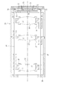
- FIG. 1 is a cross-sectional view showing a configuration of a lens apparatus according to the present invention.
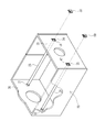
- FIG. 2 is a perspective view showing the lens barrel body.
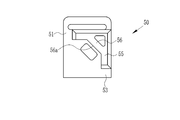
- FIG. 3 is a rear view of the shaft pressing member.
- FIG. 4 is a perspective view of the shaft pressing member viewed from the back side.
- FIG. 5 is a perspective view of the shaft pressing member viewed from the front side.
- FIG. 6 is an explanatory view showing a fixed state of the guide shaft by the shaft pressing member when viewed from the rear plate side.
- FIG. 7 is a cross-sectional view showing the configuration of the lens apparatus of the second embodiment.
- FIG. 8 is a cross-sectional view showing the configuration of the lens apparatus of the third embodiment.
- FIG. 9 is a perspective view showing a shaft pressing member used in the third embodiment.
- a lens apparatus 10 is used for a surveillance camera, and includes three first to third lens groups (hereinafter referred to as lenses) 12, 13, and 14 constituting an imaging optical system. I have. These first to third lenses are depicted as one lens element in the drawing, but are actually composed of a plurality of lens elements.
- the first lens 12 is a variator lens that changes the focal length
- the third lens 14 is a focus lens that adjusts the focus. These first and third lenses move along the optical axis 28.
- the second lens 13 is a relay lens and is fixed so as not to move. At the time of zooming, the first lens 12 moves to change the image magnification.
- the third lens 14 moves during focus adjustment. In the case of zooming, the first lens 12 and the third lens 4 move.
- the first to third lenses 12 to 14 are held by lens holding frames 16, 17 and 18. These lens holding frames 16 to 18 are accommodated in the lens barrel 20.
- the lens holding frame 17 is fixed to the lens barrel 20.
- Two guide shafts 25 and 26 parallel to the optical axis 28 are attached to the lens barrel 20.
- the lens holding frames 16 and 18 are formed with guide holes 21 and 22 each having a predetermined length and guide grooves 23 and 24 for preventing rotation.
- the guide holes 21 and 22 and the guide grooves 23 and 24 for rotation prevention are fitted to the guide shafts 25 and 26 so as to be movable in the optical axis direction.
- a lens holding frame moving mechanism is provided for each of the lens holding frames 16 and 18.
- Each lens holding frame moving mechanism includes a stepping motor and a feed screw rotated by the stepping motor.
- Each feed screw is screwed with a nut formed on the lens holding frames 16 and 18.
- the stepping motor rotates.
- the lens holding frames 16 and 18 move along the guide shafts 25 and 26 by the combination of the feed screw and the nut.
- the lens holding frames 16 and 18 may be moved by a known cam mechanism.
- the guide shaft 25 is sequentially inserted into a first support hole 34 formed in the rear plate 33 of the lens barrel 20, a hole 36 formed in the lens holding frame 17, and a guide hole 21 formed in the lens holding frame 16. After that, the tip 41 is press-fitted into the second support hole 31 formed in the front plate 30. Before the guide shaft 26 is attached, the guide groove 24 formed in the lens holding frame 18 is engaged with the guide shaft 25. Next, the guide shaft 26 is formed in the first support hole 34 formed in the rear plate 33, the guide hole 22 formed in the lens holding frame 18, the hole 37 formed in the lens holding frame 17, and the lens holding frame 16. After the guide grooves 23 are sequentially inserted, the tip 42 is press-fitted into the second support hole 32 formed in the front plate 30.
- the guide shafts 25 and 26 have front ends 41 and 42 and rear ends 44 and 45.
- Reference numerals 46 and 47 represent end surfaces (rear end surfaces) of the rear ends 44 and 45.
- the length of each side of the second support holes 31 and 33 is set. It is made smaller than the diameter of the guide shafts 25 and 26. And let this shortened area
- the ends 41 and 42 of the guide shafts 25 and 26 are pressed by the elastic force generated by deforming the elastically deforming portions with the guide shafts 25 and 26, and are securely fixed to the front plate 30.
- the shaft pressing member 50 includes a plate-like main body 51 having a front surface 52 and a back surface 53, and an A-shaped protrusion 55 formed on the back surface 53.
- the protrusion 55 is inserted into the first support holes 34 and 35 of the rear plate 33. In this state, a part of the back surface 53 comes into contact with the rear end surfaces 46 and 47 of the guide shafts 25 and 26.
- a connecting piece 65 that connects A-shaped “reverse V” extends obliquely, and the one surface serves as a pressing surface 56 to press the outer periphery of the rear ends 44, 45 of the guide shafts 25, 26.
- the shaft pressing member 50 is made of elastic plastic.
- a material having both moderate rigidity and appropriate elasticity such as urethane, nylon, and polyacetal is preferable.
- the lens barrel 20 is made of aluminum or hard plastic.
- the guide shafts 25 and 26 are made of metal.
- the first support hole 34 includes a recess 61 that fits into the edge of the main body 51 of the shaft pressing member 50 and a rectangular through hole 62 into which the protrusion 55 is inserted.
- the surface 52 of the main body 50 is flush with the rear plate 33.
- the projection 55 is press-fitted into the gap between the adjacent two sides 63 and 64 and the guide shaft 25.
- the outer periphery of the guide shaft 25 is pressed against the two adjacent sides 65 and 66 by the pressing surface 56 of the protrusion 55, and is positioned at a predetermined position.
- the outer peripheral edge of the protrusion 55 is chamfered so that it can be easily inserted into the gap. The same applies to the first support hole 35 and the shaft pressing member 50 fitted in the first support hole 35.
- the infrared cut filter 69 and the image sensor 70 are arranged as shown in FIG.
- the infrared cut filter 69 is driven by an infrared cut filter insertion / removal device (not shown) attached to the lens barrel 20.
- the image sensor 70 is fixed to an aluminum plate 71.
- a circuit board 72 is fixed behind the aluminum plate, and the image sensor 70 is soldered thereto.
- the aluminum plate 71 is fixed to a sensor holder (image sensor holding member) 73.
- the sensor holder 73 has a plate shape, is overlaid on the rear plate 33 of the lens barrel body 20, and is screwed from above.
- the sensor holder 73 is provided with a drop-off preventing surface 74 at a position covering the shaft pressing member 50, and is in contact with the surface 52 of the shaft pressing member 50.
- FIG. 7 shows a second embodiment of the lens apparatus.
- a circuit board 76 is fixed to an aluminum plate (image sensor holding member) 75.
- the image sensor 70 is fixed to the aluminum plate 75 and connected to the circuit board 76.
- a sensor cover 77 covering the image sensor 70 is fixed to the aluminum plate 75.
- the aluminum plate 75 is screwed (not shown) to the rear plate 33 of the lens barrel 20.
- the aluminum plate 75 is provided with a drop-off preventing surface 78 at a position covering the shaft pressing member 50.
- the drop prevention surface 78 abuts on the surface 52 of the main body 55 of the shaft pressing member 50 to prevent the drop off from the first support holes 34 and 35.
- the image sensor 70 is fixed to the aluminum plate 81.
- the aluminum plate 81 is fixed to a circuit board (image sensor holding member) 82.
- a sensor cover 83 that covers the image sensor 70 is fixed to the circuit board 82.
- the circuit board 82 is screwed (not shown) to the rear plate 33 of the lens barrel body 20.
- the circuit board 82 is provided with a drop-off preventing surface 84 at a position covering the shaft pressing member 80, abutting against the pressing receiving portion 85 of the shaft pressing member 80, and from the first support holes 34 and 35 of the shaft pressing member 80. Is preventing the dropout.
- the above-described shaft pressing member 50 may be used.
- the shaft pressing member 80 may be employed in the first and second embodiments.
- the shaft pressing member 80 has a receiving portion 85 that comes into contact with the drop-off prevention surface 84.
- the receiving portion 85 is a plate-like portion (extension portion) in which one end side of the main body 86 is folded back into a U shape, and is pressed by the drop prevention surface 84.
- a plurality of small spherical bosses 88 are formed on the flat surface of the receiving portion 85 and come into contact with the drop-off preventing surface 84.
- the receiving portion 85 is elastically deformed by a U-shaped curved portion when pressed by the drop-off prevention surface 84, and absorbs excessive pressing force received from the drop-off prevention surface 84, so that the circuit board 82, the guide shafts 25, 26, etc. This prevents unnecessary forces from acting on the machine.
- the front plate and the rear plate are integrally formed with the barrel main body, but the front plate and the rear plate may be fixed to the barrel main body. Also.
- the lens device of the present invention can be used for a broadcast camera, an automobile accident recording camera, and the like in addition to the monitoring camera described above.
Landscapes
- Physics & Mathematics (AREA)
- General Physics & Mathematics (AREA)
- Optics & Photonics (AREA)
- Lens Barrels (AREA)
- Accessories Of Cameras (AREA)
- Studio Devices (AREA)
Priority Applications (4)
| Application Number | Priority Date | Filing Date | Title |
|---|---|---|---|
| JP2013505964A JPWO2012128248A1 (ja) | 2011-03-24 | 2012-03-19 | レンズ装置 |
| CN2012800146750A CN103443684A (zh) | 2011-03-24 | 2012-03-19 | 镜头设备 |
| EP12761516.9A EP2690476A4 (de) | 2011-03-24 | 2012-03-19 | Linsenvorrichtung |
| US14/032,843 US20140022654A1 (en) | 2011-03-24 | 2013-09-20 | Lens apparatus |
Applications Claiming Priority (2)
| Application Number | Priority Date | Filing Date | Title |
|---|---|---|---|
| JP2011-065329 | 2011-03-24 | ||
| JP2011065329 | 2011-03-24 |
Related Child Applications (1)
| Application Number | Title | Priority Date | Filing Date |
|---|---|---|---|
| US14/032,843 Continuation US20140022654A1 (en) | 2011-03-24 | 2013-09-20 | Lens apparatus |
Publications (1)
| Publication Number | Publication Date |
|---|---|
| WO2012128248A1 true WO2012128248A1 (ja) | 2012-09-27 |
Family
ID=46879395
Family Applications (1)
| Application Number | Title | Priority Date | Filing Date |
|---|---|---|---|
| PCT/JP2012/057011 Ceased WO2012128248A1 (ja) | 2011-03-24 | 2012-03-19 | レンズ装置 |
Country Status (5)
| Country | Link |
|---|---|
| US (1) | US20140022654A1 (de) |
| EP (1) | EP2690476A4 (de) |
| JP (1) | JPWO2012128248A1 (de) |
| CN (1) | CN103443684A (de) |
| WO (1) | WO2012128248A1 (de) |
Cited By (3)
| Publication number | Priority date | Publication date | Assignee | Title |
|---|---|---|---|---|
| CN103713370A (zh) * | 2012-10-09 | 2014-04-09 | 南京理工大学 | 一种使用三坐标测量仪装调近红外大型长焦距镜头的方法 |
| JP2014174183A (ja) * | 2013-03-06 | 2014-09-22 | Konica Minolta Inc | レンズ鏡筒及び撮像装置 |
| JP2021067818A (ja) * | 2019-10-24 | 2021-04-30 | 新思考電機有限公司 | レンズ駆動装置、カメラ装置及び電子機器 |
Families Citing this family (3)
| Publication number | Priority date | Publication date | Assignee | Title |
|---|---|---|---|---|
| KR102527790B1 (ko) * | 2018-01-30 | 2023-04-28 | 엘지이노텍 주식회사 | 카메라 모듈 |
| CN112540441B (zh) * | 2019-09-06 | 2025-05-27 | 新思考电机有限公司 | 透镜驱动装置、照相机装置以及电子设备 |
| CN111123461B (zh) * | 2020-01-10 | 2025-03-21 | 中山联合光电科技股份有限公司 | 一种光学镜头结构 |
Citations (4)
| Publication number | Priority date | Publication date | Assignee | Title |
|---|---|---|---|---|
| JP2000266982A (ja) * | 1999-03-15 | 2000-09-29 | Sony Corp | レンズ鏡筒 |
| JP2005257784A (ja) * | 2004-03-09 | 2005-09-22 | Olympus Corp | カメラ及びレンズ装置及び携帯型情報機器 |
| JP2007178779A (ja) * | 2005-12-28 | 2007-07-12 | Seiko Instruments Inc | レンズ移動装置及びカメラモジュール |
| JP2010066713A (ja) | 2008-09-12 | 2010-03-25 | Fujinon Corp | レンズ装置 |
Family Cites Families (5)
| Publication number | Priority date | Publication date | Assignee | Title |
|---|---|---|---|---|
| US7061699B2 (en) * | 2002-03-28 | 2006-06-13 | Seiko Epson Corporation | Projection lens, producing method of projection lens and projector having projection lens |
| JP4487531B2 (ja) * | 2003-10-02 | 2010-06-23 | ソニー株式会社 | レンズ鏡筒 |
| JP2006163006A (ja) * | 2004-12-08 | 2006-06-22 | Nec Access Technica Ltd | カメラモジュール固定構造及びその固定方法並びにそれを用いた携帯端末 |
| US7848638B2 (en) * | 2005-10-11 | 2010-12-07 | Fujiflim Corporation | Lens assembly, lens moving device and assembling method |
| CN201096944Y (zh) * | 2007-08-21 | 2008-08-06 | 三星高新电机(天津)有限公司 | 支撑定位无调焦的手机摄像头 |
-
2012
- 2012-03-19 EP EP12761516.9A patent/EP2690476A4/de not_active Withdrawn
- 2012-03-19 CN CN2012800146750A patent/CN103443684A/zh active Pending
- 2012-03-19 WO PCT/JP2012/057011 patent/WO2012128248A1/ja not_active Ceased
- 2012-03-19 JP JP2013505964A patent/JPWO2012128248A1/ja not_active Abandoned
-
2013
- 2013-09-20 US US14/032,843 patent/US20140022654A1/en not_active Abandoned
Patent Citations (4)
| Publication number | Priority date | Publication date | Assignee | Title |
|---|---|---|---|---|
| JP2000266982A (ja) * | 1999-03-15 | 2000-09-29 | Sony Corp | レンズ鏡筒 |
| JP2005257784A (ja) * | 2004-03-09 | 2005-09-22 | Olympus Corp | カメラ及びレンズ装置及び携帯型情報機器 |
| JP2007178779A (ja) * | 2005-12-28 | 2007-07-12 | Seiko Instruments Inc | レンズ移動装置及びカメラモジュール |
| JP2010066713A (ja) | 2008-09-12 | 2010-03-25 | Fujinon Corp | レンズ装置 |
Cited By (5)
| Publication number | Priority date | Publication date | Assignee | Title |
|---|---|---|---|---|
| CN103713370A (zh) * | 2012-10-09 | 2014-04-09 | 南京理工大学 | 一种使用三坐标测量仪装调近红外大型长焦距镜头的方法 |
| JP2014174183A (ja) * | 2013-03-06 | 2014-09-22 | Konica Minolta Inc | レンズ鏡筒及び撮像装置 |
| JP2021067818A (ja) * | 2019-10-24 | 2021-04-30 | 新思考電機有限公司 | レンズ駆動装置、カメラ装置及び電子機器 |
| CN112799204A (zh) * | 2019-10-24 | 2021-05-14 | 新思考电机有限公司 | 透镜驱动装置、照相装置以及电子设备 |
| JP7183135B2 (ja) | 2019-10-24 | 2022-12-05 | 新思考電機有限公司 | レンズ駆動装置、カメラ装置及び電子機器 |
Also Published As
| Publication number | Publication date |
|---|---|
| EP2690476A4 (de) | 2014-11-05 |
| CN103443684A (zh) | 2013-12-11 |
| US20140022654A1 (en) | 2014-01-23 |
| EP2690476A1 (de) | 2014-01-29 |
| JPWO2012128248A1 (ja) | 2014-07-24 |
Similar Documents
| Publication | Publication Date | Title |
|---|---|---|
| US8559803B2 (en) | Photographing module | |
| WO2012128248A1 (ja) | レンズ装置 | |
| US8734032B2 (en) | Lens barrel having shutter flexible circuit board and image pickup apparatus having the same | |
| US8861103B2 (en) | Lens driving apparatus and optical apparatus having the same | |
| JP5109232B2 (ja) | レンズ鏡筒 | |
| JP4890040B2 (ja) | 像振れ補正装置 | |
| US8462451B2 (en) | Lens barrel and image pickup apparatus | |
| JP2017090648A (ja) | レンズユニット及び撮像装置 | |
| JP2008089803A (ja) | 撮像装置 | |
| US20200280665A1 (en) | Image blur correction device that reduces image blur of optical image, and image capture apparatus | |
| KR101594301B1 (ko) | 렌즈 이동 장치 | |
| WO2015045728A1 (ja) | レンズユニット及び撮像装置 | |
| JP6540991B2 (ja) | カム機構及び光学機器 | |
| JP2008089804A (ja) | 撮像装置 | |
| US9124790B2 (en) | Lens apparatus and image pickup apparatus | |
| JP2010032831A (ja) | 光学フィルタ保持機構、レンズ装置および撮像装置 | |
| US20190064473A1 (en) | Lens barrel and imaging apparatus | |
| US7684135B2 (en) | Lens device | |
| KR101624653B1 (ko) | 렌즈 구동 장치 | |
| JP5824658B2 (ja) | 光学機器 | |
| JP2006243147A (ja) | 光学ユニット、レンズ駆動装置、及びカメラモジュール | |
| JP2003222924A (ja) | カメラ | |
| JP5026358B2 (ja) | 撮像素子支持機構 | |
| JP2005352395A (ja) | 光学素子の挿脱装置 | |
| US20120081756A1 (en) | Mirror support device and image reader |
Legal Events
| Date | Code | Title | Description |
|---|---|---|---|
| 121 | Ep: the epo has been informed by wipo that ep was designated in this application |
Ref document number: 12761516 Country of ref document: EP Kind code of ref document: A1 |
|
| ENP | Entry into the national phase |
Ref document number: 2013505964 Country of ref document: JP Kind code of ref document: A |
|
| WWE | Wipo information: entry into national phase |
Ref document number: 2012761516 Country of ref document: EP |
|
| NENP | Non-entry into the national phase |
Ref country code: DE |