WO2012131908A1 - Heads-up display and method of attaching same - Google Patents
Heads-up display and method of attaching same Download PDFInfo
- Publication number
- WO2012131908A1 WO2012131908A1 PCT/JP2011/057834 JP2011057834W WO2012131908A1 WO 2012131908 A1 WO2012131908 A1 WO 2012131908A1 JP 2011057834 W JP2011057834 W JP 2011057834W WO 2012131908 A1 WO2012131908 A1 WO 2012131908A1
- Authority
- WO
- WIPO (PCT)
- Prior art keywords
- display
- light source
- head
- light
- attachment
- Prior art date
- Legal status (The legal status is an assumption and is not a legal conclusion. Google has not performed a legal analysis and makes no representation as to the accuracy of the status listed.)
- Ceased
Links
Images



Classifications
-
- G—PHYSICS
- G02—OPTICS
- G02B—OPTICAL ELEMENTS, SYSTEMS OR APPARATUS
- G02B27/00—Optical systems or apparatus not provided for by any of the groups G02B1/00 - G02B26/00, G02B30/00
- G02B27/01—Head-up displays
-
- B—PERFORMING OPERATIONS; TRANSPORTING
- B60—VEHICLES IN GENERAL
- B60K—ARRANGEMENT OR MOUNTING OF PROPULSION UNITS OR OF TRANSMISSIONS IN VEHICLES; ARRANGEMENT OR MOUNTING OF PLURAL DIVERSE PRIME-MOVERS IN VEHICLES; AUXILIARY DRIVES FOR VEHICLES; INSTRUMENTATION OR DASHBOARDS FOR VEHICLES; ARRANGEMENTS IN CONNECTION WITH COOLING, AIR INTAKE, GAS EXHAUST OR FUEL SUPPLY OF PROPULSION UNITS IN VEHICLES
- B60K35/00—Instruments specially adapted for vehicles; Arrangement of instruments in or on vehicles
- B60K35/20—Output arrangements, i.e. from vehicle to user, associated with vehicle functions or specially adapted therefor
- B60K35/21—Output arrangements, i.e. from vehicle to user, associated with vehicle functions or specially adapted therefor using visual output, e.g. blinking lights or matrix displays
- B60K35/23—Head-up displays [HUD]
-
- B—PERFORMING OPERATIONS; TRANSPORTING
- B60—VEHICLES IN GENERAL
- B60K—ARRANGEMENT OR MOUNTING OF PROPULSION UNITS OR OF TRANSMISSIONS IN VEHICLES; ARRANGEMENT OR MOUNTING OF PLURAL DIVERSE PRIME-MOVERS IN VEHICLES; AUXILIARY DRIVES FOR VEHICLES; INSTRUMENTATION OR DASHBOARDS FOR VEHICLES; ARRANGEMENTS IN CONNECTION WITH COOLING, AIR INTAKE, GAS EXHAUST OR FUEL SUPPLY OF PROPULSION UNITS IN VEHICLES
- B60K35/00—Instruments specially adapted for vehicles; Arrangement of instruments in or on vehicles
- B60K35/50—Instruments characterised by their means of attachment to or integration in the vehicle
-
- B—PERFORMING OPERATIONS; TRANSPORTING
- B60—VEHICLES IN GENERAL
- B60K—ARRANGEMENT OR MOUNTING OF PROPULSION UNITS OR OF TRANSMISSIONS IN VEHICLES; ARRANGEMENT OR MOUNTING OF PLURAL DIVERSE PRIME-MOVERS IN VEHICLES; AUXILIARY DRIVES FOR VEHICLES; INSTRUMENTATION OR DASHBOARDS FOR VEHICLES; ARRANGEMENTS IN CONNECTION WITH COOLING, AIR INTAKE, GAS EXHAUST OR FUEL SUPPLY OF PROPULSION UNITS IN VEHICLES
- B60K35/00—Instruments specially adapted for vehicles; Arrangement of instruments in or on vehicles
- B60K35/60—Instruments characterised by their location or relative disposition in or on vehicles
-
- G—PHYSICS
- G02—OPTICS
- G02B—OPTICAL ELEMENTS, SYSTEMS OR APPARATUS
- G02B27/00—Optical systems or apparatus not provided for by any of the groups G02B1/00 - G02B26/00, G02B30/00
- G02B27/01—Head-up displays
- G02B27/0101—Head-up displays characterised by optical features
-
- B—PERFORMING OPERATIONS; TRANSPORTING
- B60—VEHICLES IN GENERAL
- B60K—ARRANGEMENT OR MOUNTING OF PROPULSION UNITS OR OF TRANSMISSIONS IN VEHICLES; ARRANGEMENT OR MOUNTING OF PLURAL DIVERSE PRIME-MOVERS IN VEHICLES; AUXILIARY DRIVES FOR VEHICLES; INSTRUMENTATION OR DASHBOARDS FOR VEHICLES; ARRANGEMENTS IN CONNECTION WITH COOLING, AIR INTAKE, GAS EXHAUST OR FUEL SUPPLY OF PROPULSION UNITS IN VEHICLES
- B60K2360/00—Indexing scheme associated with groups B60K35/00 or B60K37/00 relating to details of instruments or dashboards
- B60K2360/20—Optical features of instruments
- B60K2360/27—Optical features of instruments using semi-transparent optical elements
-
- B—PERFORMING OPERATIONS; TRANSPORTING
- B60—VEHICLES IN GENERAL
- B60K—ARRANGEMENT OR MOUNTING OF PROPULSION UNITS OR OF TRANSMISSIONS IN VEHICLES; ARRANGEMENT OR MOUNTING OF PLURAL DIVERSE PRIME-MOVERS IN VEHICLES; AUXILIARY DRIVES FOR VEHICLES; INSTRUMENTATION OR DASHBOARDS FOR VEHICLES; ARRANGEMENTS IN CONNECTION WITH COOLING, AIR INTAKE, GAS EXHAUST OR FUEL SUPPLY OF PROPULSION UNITS IN VEHICLES
- B60K2360/00—Indexing scheme associated with groups B60K35/00 or B60K37/00 relating to details of instruments or dashboards
- B60K2360/20—Optical features of instruments
- B60K2360/33—Illumination features
- B60K2360/334—Projection means
-
- B—PERFORMING OPERATIONS; TRANSPORTING
- B60—VEHICLES IN GENERAL
- B60K—ARRANGEMENT OR MOUNTING OF PROPULSION UNITS OR OF TRANSMISSIONS IN VEHICLES; ARRANGEMENT OR MOUNTING OF PLURAL DIVERSE PRIME-MOVERS IN VEHICLES; AUXILIARY DRIVES FOR VEHICLES; INSTRUMENTATION OR DASHBOARDS FOR VEHICLES; ARRANGEMENTS IN CONNECTION WITH COOLING, AIR INTAKE, GAS EXHAUST OR FUEL SUPPLY OF PROPULSION UNITS IN VEHICLES
- B60K2360/00—Indexing scheme associated with groups B60K35/00 or B60K37/00 relating to details of instruments or dashboards
- B60K2360/77—Instrument locations other than the dashboard
- B60K2360/771—Instrument locations other than the dashboard on the ceiling
-
- B—PERFORMING OPERATIONS; TRANSPORTING
- B60—VEHICLES IN GENERAL
- B60Y—INDEXING SCHEME RELATING TO ASPECTS CROSS-CUTTING VEHICLE TECHNOLOGY
- B60Y2304/00—Optimising design; Manufacturing; Testing
- B60Y2304/09—Testing or calibrating during manufacturing
Definitions
- the present invention relates to a head-up display installed on a moving body.
- Patent Document 1 discloses a head-up display that includes a display device and a combiner and is installed on a vehicle interior ceiling.
- an optical element such as a light source unit including a light source and a combiner is fixed to a vehicle body side using screws or the like at a ceiling portion of a passenger compartment.
- the ceiling of the passenger compartment is not necessarily flat and may have protrusions such as lining.
- the light beam emitted from the light source unit to the optical element may be blocked by the protrusions protruding from the ceiling, so that the optical element cannot be correctly irradiated with the light beam.
- An object of the present invention is to provide a head-up display that can be easily installed in a state where light emitted from a light source unit is not blocked by protrusions or the like on the ceiling of a vehicle compartment.
- the invention according to claim 1 is a head-up display mounted on a moving body, wherein a light source unit on which a light source for irradiating light is mounted to form a virtual image, and light from the light source is irradiated.
- a display unit having an optical element, and a connection member that connects the light source unit and the display unit, and at least a part of the connection member includes the light source unit and the display unit to which the moving body is attached.
- a suppressing part is formed that suppresses an optical path region formed between the light source part and the display part from being blocked by the attachment target part.
- the invention according to claim 9 is an attachment method for attaching the head-up display to the attachment target portion of the moving body, and includes a light source unit on which a light source that emits light to form a virtual image is mounted;
- the connecting step of connecting a display unit having an optical element irradiated with light by a connecting member, and the optical path region formed between the light source unit and the display unit so as not to be blocked by the attachment target site
- the invention according to claim 10 is a head-up display, in which a light source unit on which light is emitted to form a virtual image having a vertical direction is mounted, and an optical element on which light from the light source is irradiated And a connecting member that connects the light source unit and the display unit, and at least a part of the connecting member is configured such that the light for forming the virtual image is the light source unit and the display unit.
- the optical path region is formed so as to exist above the uppermost end of the optical path region formed therebetween.
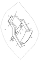
- FIG. 1 It is a figure which shows typically the state which installed the head up display which concerns on an Example in the vehicle interior. It is the perspective view which looked at the head-up display from diagonally downward. It is a figure which shows typically the optical path area
- a head-up display mounted on a moving body is irradiated with light from a light source unit on which a light source that emits light to form a virtual image is mounted, and light from the light source.
- a display unit having an optical element, and a connection member that connects the light source unit and the display unit, and at least a part of the connection member includes the light source unit and the display unit to which the moving body is attached.
- a suppressing part is formed that suppresses an optical path region formed between the light source part and the display part from being blocked by the attachment target part.
- the light source unit and the display unit are connected by the connecting member, and the light emitted from the light source is irradiated onto the optical element of the display unit.
- the suppression part formed in at least a part of the connection member suppresses that the optical path region formed between the light source part and the display part by the light from the light source is blocked by the attachment target part of the moving body. To do. Therefore, when the head-up display is attached to the moving body, the light from the light source is prevented from being blocked by the attachment target portion of the moving body, and a part of the display image is not lost.
- the suppressing portion is formed by projecting a part of the connection member toward the mounting surface from the optical path region.
- the virtual image has a vertical direction, and as the suppressing portion, at least a part of the connection member exists above the uppermost end of the optical path region. Is formed. Thereby, in a state where at least a part of the connection member is in contact with the attachment target part, the attachment target part is located above the uppermost end of the optical path area, and the optical path area is not blocked.
- head-up display further includes an attachment member for attaching the head-up display close to a part of the attachment surface of the moving body as the attachment target part, and the suppression unit Restricts the optical path region from approaching the attachment surface when the head-up display is attached to the moving body by the attachment member. Thereby, it is prevented that an optical path area
- connection member connects the light source unit and the display unit in at least one of the left and right directions of the virtual image, and the connection in the upward direction of the virtual image as the suppression unit.
- the end portion of the member is formed so as to exist above the uppermost end of the optical path region.
- head-up display has a bridge portion that is located above the uppermost end of the optical path region and extends in the left-right direction of the virtual image.
- the attachment aspect part in a state where the bridge portion is in contact with the attachment target part, the attachment aspect part is above the uppermost end of the optical path area, and the optical path area is not blocked.
- the bridge portion is configured to be detachable. Therefore, after attaching a head-up display to a moving body using a bridge part, a bridge part can be removed.
- the head-up display has an attachment member for attaching the head-up display to the moving body, and the side on which the attachment member is formed with respect to the display unit is defined as an upward direction in the virtual image.
- an attachment method for attaching the head-up display to the attachment target part of the moving body includes: a light source unit on which a light source that emits light to form a virtual image is mounted; The connecting step of connecting a display unit having an optical element irradiated with light by a connecting member, and the optical path region formed between the light source unit and the display unit so as not to be blocked by the attachment target site; An attachment step of disposing a suppressing portion provided on at least a part of a connection member with respect to the attachment target site, and attaching the light source unit and the display unit connected by the connection member to the attachment target site;
- the suppression part provided in at least a part of the connection member is arranged with respect to the attachment target part so that the optical path region formed between the light source part and the display part is not blocked by the attachment target part.
- the head-up display is arranged and attached to the attachment target part of the moving body.
- the head-up display includes a light source unit on which a light source that emits light to form a virtual image having a vertical direction is mounted, and an optical element that is irradiated with light from the light source And a connecting member that connects the light source unit and the display unit, and at least a part of the connecting member is configured such that the light for forming the virtual image is the light source unit and the display unit. Is formed so as to exist above the uppermost end of the optical path region formed between the two.
- the light source unit and the display unit are connected by the connecting member, and the light emitted from the light source is irradiated onto the optical element of the display unit.
- the connection member is formed such that the light for forming a virtual image exists above the uppermost end of the optical path region formed between the light source unit and the display unit. Therefore, when the head-up display is attached to the moving body, the light from the light source is prevented from being blocked by the attachment target portion of the moving body, and a part of the display image is not lost.
- FIG. 1 schematically shows a state in which the head-up display according to the embodiment is installed in a vehicle cabin.
- FIG. 1 is a side view of the driver's seat of the vehicle 1, and the driver 7 sits on the seat 5 in the passenger compartment.
- a windshield 4 of the vehicle 1 is located in front of the driver 7.
- the head-up display 10 is installed diagonally upward in front of the driver 7. Although details will be described later, the head-up display 10 includes a light source unit 11 and a combiner 12. As indicated by a broken line, the light emitted from the light source unit 11 is reflected by the combiner 12 and reaches the eyes of the driver 7. Accordingly, the driver 7 visually recognizes the virtual image 30 at a position in front of the vehicle. Note that the tip of the arrow of the virtual image 30 indicates the upward direction.
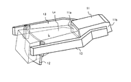
- FIG. 2 is a perspective view of the head-up display 10 as viewed obliquely from below.
- the head-up display 10 includes a light source unit 11, a combiner 12, a pair of arms 13, and an attachment stay 14.
- the mounting stay 14 is a member that serves as a base when the head-up display 10 is attached to the vehicle.
- the mounting stay 14 is a T-shaped flat plate and has a plurality of elongated holes 14a.
- the mounting stay 14 is fixed to the mounting hole provided in the ceiling 3 of the passenger compartment by screws 15.
- the light source unit 11 is equipped with a light source (not shown) such as a laser diode.
- the light emitted from the light source unit 11 is projected to the combiner 12.
- the combiner 12 reflects the light emitted from the light source unit 11 toward the eyes of the driver 7.
- the light source unit 11 is fixed to the mounting stay 14 with, for example, screws.
- a pair of arms 13 are attached to the side surface 11 b of the light source unit 11.
- a pair of combiner holding portions 16 that hold the combiner 12 is provided near the tip of the arm 13, that is, near the end opposite to the light source portion 11.
- the pair of combiner holding portions 16 holds the combiner 12 from the left and right.
- the combiner 12 is an example of the optical element of the present invention
- the arm 13 is an example of a connection member
- the attachment stay 14 is an example of an attachment member.
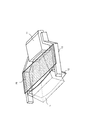
- FIG. 3 is a perspective view of the head-up display 10 as viewed obliquely from above.
- the illustration of the mounting stay 14 is omitted.
- Projection light emitted from a light source provided inside the light source unit 11 forms an effective projection shape L.
- the effective projection shape L is also referred to as “optical path region L”.
- the intermediate image is displayed on the intermediate image display unit 11 a provided in front of the light source unit 11 by the light emitted from the light source.
- FIG. 4 shows the positional relationship between the head-up display and the optical path region L when a part of the ceiling 3 (hereinafter referred to as a “projecting portion”) 3x projects downward.
- the protruding portion 3x is located in the optical path region L of the projection light emitted from the light source unit 11. A part of the projection light is blocked by the protruding portion 3x, and a part of the virtual image 30 visually recognized by the driver 7 is lost.
- the head-up display when the head-up display is attached to the passenger compartment, it is still not possible to irradiate the projection light from the light source unit, so that the person performing the attachment (hereinafter simply referred to as “user”) extends to the optical path region L. I can not know. Therefore, it is not uncommon for the projection light 3 to be interrupted by the protruding portion 3x only after the attachment of the head-up display 10 is completed and the light source is driven.
- the combiner 12 is held by the pair of arms 13 from the left and right, and the upper surface of the arm 13 is positioned above the upper surface of the optical path region L, that is, the uppermost end.
- the “upward direction” is the upward direction of the virtual image 30 shown in FIG. 1 and refers to the side on which the mounting stay 14 is located with reference to the combiner 12 as a display unit.
- the upper surface 13x of the arm 13 corresponds to a suppressing portion of the present invention.
- the upper surface 13x of the arm 13 is extended to the protruding portion 3x. Therefore, the head-up display 10 cannot be attached above it. Since the upper surface Lx of the optical path region L is below the upper surface 13x of the arm 13, the protruding portion 3x of the ceiling 3 does not block the optical path region L. In other words, the upper surface 13x of the arm 13 has a role of restricting the optical path region L from approaching the ceiling 3 any more by hitting the protruding portion 3x of the ceiling 3.
- the protruding portion 3 x may block the optical path region L. Is prevented.
- the user can easily attach the head-up display 10 to an appropriate position without being aware of the optical path region L and without actually operating the light source unit 11 to emit projection light.
- the user attaches the pair of arms 13 to the side surface 11 b of the light source unit 11 and attaches the combiner 12 to the arm 13 using the combiner holding unit 16. That is, the light source unit 11 and the combiner 12 are connected by the arm 13.
- the user adjusts the mounting position and mounting angle of the arm 13 with respect to the light source unit 11 so that the upper surface 13x of the arm 13 is positioned above the upper surface Lx of the optical path region L, as shown in FIG. To do.
- the user when the projection light is emitted perpendicularly to the surface of the intermediate image display unit 11a of the light source unit 11, the user can position the upper surface 13x of the arm 13 above the upper end of the intermediate image display unit 11a.
- the arm 13 is attached to the light source unit 11 so that the upper surface 13x of the arm 13 is substantially perpendicular to the surface of the display unit 11a. In this way, the light source unit 11, the combiner 12, and the arm 13 are integrated.
- the user attaches the attachment stay 14 to the ceiling 3 of the vehicle. Then, the user attaches the light source unit 11 integrated with the combiner 12 and the arm 13 to the attachment stay 14. At this time, the user sets the position where the upper surface 13x of the arm 13 hits the ceiling 3 as the upper limit, that is, the position closest to the ceiling 3. This prevents the protruding portion 3x of the ceiling 3 from blocking the optical path region L.
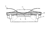
- the head-up display 10 When the head-up display 10 is attached, the work is performed with the bridge portion 20 attached to the arm 13. In this case, since the bridge portion 20 hits the protruding portion 3x of the ceiling 3 of the passenger compartment, the user cannot attach the head-up display 10 closer to the ceiling 3 any more. Since the upper surface Lx of the optical path region L is below the upper surface 13x of the arm 13, the protruding portion 3x of the ceiling 3 does not block the optical path region L. In other words, in the above embodiment, the left and right arms 13 restrict the protruding portion 3x of the ceiling 3 from entering the optical path region L with a pair of lines, whereas in the modified example, the protruding portion 3x of the ceiling 3 has the optical path. The bridge portion 20 restricts entry into the region L by the surface.
- the bridge 20 is not necessary, but rather it gives a feeling of pressure if left on the user's head. Therefore, it is preferable that the user removes the bridge portion 20 from the arm 13 after attaching the head-up display 10.
- the present invention can be used for a head-up display installed on a moving body such as a vehicle.
Landscapes
- Engineering & Computer Science (AREA)
- Physics & Mathematics (AREA)
- Chemical & Material Sciences (AREA)
- Combustion & Propulsion (AREA)
- Transportation (AREA)
- Mechanical Engineering (AREA)
- General Physics & Mathematics (AREA)
- Optics & Photonics (AREA)
- Instrument Panels (AREA)
Abstract
Description
本発明は、移動体に設置されるヘッドアップディスプレイに関する。 The present invention relates to a head-up display installed on a moving body.
車両の運転席近傍に取り付けられるヘッドアップディスプレイが知られている。例えば、特許文献1は、表示装置とコンバイナとを備え、車両の室内天井部に設置されるヘッドアップディスプレイを開示している。 A head-up display that is installed near the driver's seat of a vehicle is known. For example, Patent Document 1 discloses a head-up display that includes a display device and a combiner and is installed on a vehicle interior ceiling.
一般的に、光源を備える光源ユニット及びコンバイナなどの光学素子は、車室の天井部において車体側にネジなどを用いて固定される。 Generally, an optical element such as a light source unit including a light source and a combiner is fixed to a vehicle body side using screws or the like at a ceiling portion of a passenger compartment.
しかし、車室の天井部は平坦であるとは限らず、内張りなどの突起物が設けられている場合がある。この場合、光源ユニットから光学素子へと出射された光線が、天井から張り出した突起物により遮られてしまい、光学素子に光線を正しく照射できないという不具合が起こりうる。 However, the ceiling of the passenger compartment is not necessarily flat and may have protrusions such as lining. In this case, the light beam emitted from the light source unit to the optical element may be blocked by the protrusions protruding from the ceiling, so that the optical element cannot be correctly irradiated with the light beam.
本発明が解決しようとする課題としては、上記のものが例として挙げられる。本発明は、光源部から出射した光線が車室天井部の突起物などにより遮られない状態で容易に設置可能なヘッドアップディスプレイを提供することを目的とする。 The above are examples of problems to be solved by the present invention. An object of the present invention is to provide a head-up display that can be easily installed in a state where light emitted from a light source unit is not blocked by protrusions or the like on the ceiling of a vehicle compartment.
請求項1に記載の発明は、移動体に搭載されるヘッドアップディスプレイであって、虚像を形成させるために光を照射する光源が搭載された光源部と、前記光源からの光が照射される光学素子を有する表示部と、前記光源部と前記表示部とを繋ぐ接続部材と、を備え、前記接続部材の少なくとも一部には、前記光源部と前記表示部とが前記移動体の取付対象部位に取り付けられる際に、当該光源部と当該表示部との間に形成される光路領域が前記取付対象部位によって遮られることを抑制する抑制部が形成されていることを特徴とする。 The invention according to claim 1 is a head-up display mounted on a moving body, wherein a light source unit on which a light source for irradiating light is mounted to form a virtual image, and light from the light source is irradiated. A display unit having an optical element, and a connection member that connects the light source unit and the display unit, and at least a part of the connection member includes the light source unit and the display unit to which the moving body is attached. When being attached to a part, a suppressing part is formed that suppresses an optical path region formed between the light source part and the display part from being blocked by the attachment target part.
請求項9に記載の発明は、ヘッドアップディスプレイを移動体の取付対象部位に取り付ける取付方法であって、虚像を形成させるために光を照射する光源が搭載された光源部と、前記光源からの光が照射される光学素子を有する表示部とを、接続部材によって繋ぐ接続工程と、前記光源部と前記表示部との間に形成される光路領域が前記取付対象部位によって遮られないように前記接続部材の少なくとも一部に設けられた抑制部を前記取付対象部位に対して配置し、前記接続部材により繋がれた前記光源部及び前記表示部を前記取付対象部位に対して取り付ける取付工程と、を有することを特徴とする。 The invention according to claim 9 is an attachment method for attaching the head-up display to the attachment target portion of the moving body, and includes a light source unit on which a light source that emits light to form a virtual image is mounted; The connecting step of connecting a display unit having an optical element irradiated with light by a connecting member, and the optical path region formed between the light source unit and the display unit so as not to be blocked by the attachment target site An attachment step of disposing a suppressing portion provided on at least a part of a connection member with respect to the attachment target site, and attaching the light source unit and the display unit connected by the connection member to the attachment target site; It is characterized by having.
請求項10に記載の発明は、ヘッドアップディスプレイであって、上下方向を有する虚像を形成させるために光を照射する光源が搭載された光源部と、前記光源からの光が照射される光学素子を有する表示部と、前記光源部と前記表示部とを繋ぐ接続部材と、を有し、前記接続部材の少なくとも一部は、前記虚像を形成するための前記光が前記光源部と前記表示部との間で形成する光路領域の最上端よりも上方向に存在するように形成されていることを特徴とする。 The invention according to claim 10 is a head-up display, in which a light source unit on which light is emitted to form a virtual image having a vertical direction is mounted, and an optical element on which light from the light source is irradiated And a connecting member that connects the light source unit and the display unit, and at least a part of the connecting member is configured such that the light for forming the virtual image is the light source unit and the display unit. The optical path region is formed so as to exist above the uppermost end of the optical path region formed therebetween.
本発明の1つの好適な実施形態では、移動体に搭載されるヘッドアップディスプレイは、虚像を形成させるために光を照射する光源が搭載された光源部と、前記光源からの光が照射される光学素子を有する表示部と、前記光源部と前記表示部とを繋ぐ接続部材と、を備え、前記接続部材の少なくとも一部には、前記光源部と前記表示部とが前記移動体の取付対象部位に取り付けられる際に、当該光源部と当該表示部との間に形成される光路領域が前記取付対象部位によって遮られることを抑制する抑制部が形成されている。 In one preferred embodiment of the present invention, a head-up display mounted on a moving body is irradiated with light from a light source unit on which a light source that emits light to form a virtual image is mounted, and light from the light source. A display unit having an optical element, and a connection member that connects the light source unit and the display unit, and at least a part of the connection member includes the light source unit and the display unit to which the moving body is attached. When attached to the part, a suppressing part is formed that suppresses an optical path region formed between the light source part and the display part from being blocked by the attachment target part.
上記のヘッドアップディスプレイによれば、光源部と表示部とが接続部材により接続され、光源から出射された光が表示部の光学素子へ照射される。ここで、接続部材の少なくとも一部に形成された抑制部は、光源からの光によって光源部と表示部との間に形成される光路領域が、移動体の取付対象部位によって遮られることを抑制する。よって、ヘッドアップディスプレイを移動体に取り付けたときに、光源からの光が移動体の取付対象部位により遮られることが防止され、表示画像の一部が欠けたりすることがなくなる。 According to the above head-up display, the light source unit and the display unit are connected by the connecting member, and the light emitted from the light source is irradiated onto the optical element of the display unit. Here, the suppression part formed in at least a part of the connection member suppresses that the optical path region formed between the light source part and the display part by the light from the light source is blocked by the attachment target part of the moving body. To do. Therefore, when the head-up display is attached to the moving body, the light from the light source is prevented from being blocked by the attachment target portion of the moving body, and a part of the display image is not lost.
上記のヘッドアップディスプレイの一態様では、前記抑制部は、前記接続部材の一部を、前記光路領域よりも前記取付面側へ突出させて形成されている。 In one aspect of the above-described head-up display, the suppressing portion is formed by projecting a part of the connection member toward the mounting surface from the optical path region.
上記のヘッドアップディスプレイの他の一態様では、前記虚像は上下方向を有し、前記抑制部として、前記接続部材の少なくとも一部が、前記光路領域の最上端よりも上方向に存在するように形成されている。これにより、接続部材の少なくとも一部が取付対象部位に当たっている状態で、取付対象部位は光路領域の最上端より上方向にあり、光路領域が遮られることがない。 In another aspect of the head-up display, the virtual image has a vertical direction, and as the suppressing portion, at least a part of the connection member exists above the uppermost end of the optical path region. Is formed. Thereby, in a state where at least a part of the connection member is in contact with the attachment target part, the attachment target part is located above the uppermost end of the optical path area, and the optical path area is not blocked.
上記のヘッドアップディスプレイの他の一態様は、前記ヘッドアップディスプレイを、前記取付対象部位としての前記移動体の一部の取付面に近接させて取り付けるための取付部材を更に有し、前記抑制部は、前記ヘッドアップディスプレイが前記取付部材によって前記移動体に対して取り付けられる際に、前記光路領域が前記取付面に対して近接するのを規制する。これにより、光路領域が取付対象部位により遮られることが防止される。 Another aspect of the above-described head-up display further includes an attachment member for attaching the head-up display close to a part of the attachment surface of the moving body as the attachment target part, and the suppression unit Restricts the optical path region from approaching the attachment surface when the head-up display is attached to the moving body by the attachment member. Thereby, it is prevented that an optical path area | region is obstruct | occluded by the attachment object site | part.
上記のヘッドアップディスプレイの他の一態様では、前記接続部材は、前記虚像の左右方向の少なくとも一方において前記光源部と前記表示部とを繋ぎ、前記抑制部として、前記虚像の上方向における前記接続部材の端部が、前記光路領域の最上端よりも上方向に存在するように形成されている。これにより、接続部材の端部が取付対象部位に当たっている状態で、取付対象部位は光路領域の最上端より上方向にあり、光路領域が遮られることがない。 In another aspect of the head-up display, the connection member connects the light source unit and the display unit in at least one of the left and right directions of the virtual image, and the connection in the upward direction of the virtual image as the suppression unit. The end portion of the member is formed so as to exist above the uppermost end of the optical path region. Thereby, in a state where the end portion of the connection member is in contact with the attachment target portion, the attachment target portion is above the uppermost end of the optical path region, and the optical path region is not blocked.
上記のヘッドアップディスプレイの他の一態様は、前記光路領域の最上端よりも上方向に位置し、前記虚像の左右方向に延在するブリッジ部を有する。この態様では、ブリッジ部が取付対象部位に当たっている状態で、取付態様部位は光路領域の最上端より上方向にあり、光路領域が遮られることがない。 Another embodiment of the head-up display has a bridge portion that is located above the uppermost end of the optical path region and extends in the left-right direction of the virtual image. In this aspect, in a state where the bridge portion is in contact with the attachment target part, the attachment aspect part is above the uppermost end of the optical path area, and the optical path area is not blocked.
この場合の好適な例では、前記ブリッジ部は、着脱可能に構成されている。よって、ブリッジ部を用いてヘッドアップディスプレイを移動体に取り付けた後、ブリッジ部を取り外すことができる。 In a preferred example in this case, the bridge portion is configured to be detachable. Therefore, after attaching a head-up display to a moving body using a bridge part, a bridge part can be removed.
上記のヘッドアップディスプレイは、前記ヘッドアップディスプレイを前記移動体に対して取り付けるための取付部材を有し、前記表示部を基準として前記取付部材が形成されている側が前記虚像における上方向と規定される。 The head-up display has an attachment member for attaching the head-up display to the moving body, and the side on which the attachment member is formed with respect to the display unit is defined as an upward direction in the virtual image. The
本発明の他の好適な実施形態では、ヘッドアップディスプレイを移動体の取付対象部位に取り付ける取付方法は、虚像を形成させるために光を照射する光源が搭載された光源部と、前記光源からの光が照射される光学素子を有する表示部とを、接続部材によって繋ぐ接続工程と、前記光源部と前記表示部との間に形成される光路領域が前記取付対象部位によって遮られないように前記接続部材の少なくとも一部に設けられた抑制部を前記取付対象部位に対して配置し、前記接続部材により繋がれた前記光源部及び前記表示部を前記取付対象部位に対して取り付ける取付工程と、を有する。 In another preferred embodiment of the present invention, an attachment method for attaching the head-up display to the attachment target part of the moving body includes: a light source unit on which a light source that emits light to form a virtual image is mounted; The connecting step of connecting a display unit having an optical element irradiated with light by a connecting member, and the optical path region formed between the light source unit and the display unit so as not to be blocked by the attachment target site An attachment step of disposing a suppressing portion provided on at least a part of a connection member with respect to the attachment target site, and attaching the light source unit and the display unit connected by the connection member to the attachment target site; Have
この方法によれば、光源部と表示部との間に形成される光路領域が取付対象部位によって遮られないように接続部材の少なくとも一部に設けられた抑制部を前記取付対象部位に対して配置してヘッドアップディスプレイが移動体の取付対象部位に取り付けられる。 According to this method, the suppression part provided in at least a part of the connection member is arranged with respect to the attachment target part so that the optical path region formed between the light source part and the display part is not blocked by the attachment target part. The head-up display is arranged and attached to the attachment target part of the moving body.
本発明の他の好適な実施形態では、ヘッドアップディスプレイは、上下方向を有する虚像を形成させるために光を照射する光源が搭載された光源部と、前記光源からの光が照射される光学素子を有する表示部と、前記光源部と前記表示部とを繋ぐ接続部材と、を有し、前記接続部材の少なくとも一部は、前記虚像を形成するための前記光が前記光源部と前記表示部との間で形成する光路領域の最上端よりも上方向に存在するように形成されている。 In another preferred embodiment of the present invention, the head-up display includes a light source unit on which a light source that emits light to form a virtual image having a vertical direction is mounted, and an optical element that is irradiated with light from the light source And a connecting member that connects the light source unit and the display unit, and at least a part of the connecting member is configured such that the light for forming the virtual image is the light source unit and the display unit. Is formed so as to exist above the uppermost end of the optical path region formed between the two.
上記のヘッドアップディスプレイによれば、光源部と表示部とが接続部材により接続され、光源から出射された光が表示部の光学素子へ照射される。ここで、接続部材の少なくとも一部は、虚像を形成するための前記光が光源部と表示部との間で形成する光路領域の最上端よりも上方向に存在するように形成されている。よって、ヘッドアップディスプレイを移動体に取り付けたときに、光源からの光が移動体の取付対象部位により遮られることが防止され、表示画像の一部が欠けたりすることがなくなる。 According to the above head-up display, the light source unit and the display unit are connected by the connecting member, and the light emitted from the light source is irradiated onto the optical element of the display unit. Here, at least a part of the connection member is formed such that the light for forming a virtual image exists above the uppermost end of the optical path region formed between the light source unit and the display unit. Therefore, when the head-up display is attached to the moving body, the light from the light source is prevented from being blocked by the attachment target portion of the moving body, and a part of the display image is not lost.
以下、図面を参照して本発明の好適な実施例について説明する。 Hereinafter, preferred embodiments of the present invention will be described with reference to the drawings.
図1は、実施例に係るヘッドアップディスプレイを車両の車室内に設置した状態を模式的に示す。図1は、車両1の運転席を側方から見た図であり、運転者7は車室内のシート5に座っている。運転者7の頭上には車両のルーフ2があり、その下方には車室の天井3がある。また、運転者7の前方には車両1のフロントガラス4がある。
FIG. 1 schematically shows a state in which the head-up display according to the embodiment is installed in a vehicle cabin. FIG. 1 is a side view of the driver's seat of the vehicle 1, and the driver 7 sits on the seat 5 in the passenger compartment. There is a roof 2 of the vehicle above the driver 7 and a
ヘッドアップディスプレイ10は、運転者7の前方斜め上方向に設置される。詳細は後述するが、ヘッドアップディスプレイ10は、光源部11とコンバイナ12とを備える。破線で示すように、光源部11から出射された光は、コンバイナ12で反射され、運転者7の目に至る。これにより、運転者7は車両前方の位置に虚像30を視認する。なお、虚像30は矢印の先端が上方向を示す。
The head-up display 10 is installed diagonally upward in front of the driver 7. Although details will be described later, the head-up display 10 includes a
図2は、ヘッドアップディスプレイ10を斜め下方向から見た斜視図である。ヘッドアップディスプレイ10は、光源部11と、コンバイナ12と、一対のアーム13と、取付ステー14とを備える。
FIG. 2 is a perspective view of the head-up display 10 as viewed obliquely from below. The head-up display 10 includes a
取付ステー14は、ヘッドアップディスプレイ10を車両に取り付ける際の土台となる部材である。本実施例では、取付ステー14はT字型の平板であり、複数の長穴14aが形成されている。取付ステー14は、車室の天井3に設けられた取付穴に対してネジ15により固定される。
The mounting
光源部11には、レーザダイオードなどの光源(図示せず)が搭載されている。光源部11から出射した光はコンバイナ12へ投射される。コンバイナ12は、光源部11から出射された光を運転者7の目の方向へ反射する。光源部11は、取付ステー14に対して例えばネジなどにより固定されている。
The
光源部11の側面11bには、一対のアーム13が取り付けられている。アーム13の先端付近、即ち、光源部11と反対側の端部付近にはコンバイナ12を保持する一対のコンバイナ保持部16が設けられている。一対のコンバイナ保持部16は、左右からコンバイナ12を保持する。
A pair of
以上の構成において、コンバイナ12は本発明の光学素子の一例であり、アーム13は接続部材の一例であり、取付ステー14は取付部材の一例である。
In the above configuration, the
図3は、ヘッドアップディスプレイ10を斜め上方向から見た斜視図である。なお、便宜上、取付ステー14の図示を省略してある。光源部11内部に設けられた光源から出射された投射光は有効投影形状Lを形成する。以下、有効投影形状Lを「光路領域L」とも呼ぶ。光源から出射した光により、光源部11の前面に設けられた中間像表示部11aには中間像が表示される。
FIG. 3 is a perspective view of the head-up display 10 as viewed obliquely from above. For convenience, the illustration of the mounting
次に、アームを有しないヘッドアップディスプレイを車両に取り付けた例を説明する。車両の種類によっては、車室の天井3の内張りなどの一部が下方に突出した形状となっている場合がある。図4は、天井3の一部(以下、「突出部分」と呼ぶ。)3xが下方に突出している場合のヘッドアップディスプレイと光路領域Lとの位置関係を示す。
Next, an example in which a head-up display without an arm is attached to a vehicle will be described. Depending on the type of vehicle, a part of the lining of the
図示のように、アームを有しないヘッドアップディスプレイを、車室の天井3に最も接近させて取り付けた場合、光源部11から出射された投射光の光路領域L内に突出部分3xが位置するため、投射光の一部が突出部分3xにより遮られてしまい、運転者7が視認する虚像30の一部が欠けてしまう。
As shown in the drawing, when a head-up display without an arm is attached closest to the
通常、ヘッドアップディスプレイを車室に取り付ける際には、未だ光源部から投射光を照射することはできないので、取り付けを行う者(以下、単に「ユーザ」と呼ぶ。)は光路領域Lがどこまで及ぶのかを知ることができない。よって、ヘッドアップディスプレイ10の取り付けを完了し、光源を駆動してみて初めて投射光が突出部分3xにより遮られてしまうことがわかるということも少なくない。
Usually, when the head-up display is attached to the passenger compartment, it is still not possible to irradiate the projection light from the light source unit, so that the person performing the attachment (hereinafter simply referred to as “user”) extends to the optical path region L. I can not know. Therefore, it is not uncommon for the
そこで、本実施例では、一対のアーム13により左右からコンバイナ12を保持する構造とし、かつ、アーム13の上面が光路領域Lの上面、即ち最上端よりも上方向に位置するようにした。具体的には、図5(a)に示すように、光路領域Lの上面Lxよりも、アーム13の上面13xが上方向に位置するように、光源部11、コンバイナ12、アーム13及びコンバイナ保持部16を組み立てる。ここで、「上方向」とは、図1に示す虚像30の上方向であり、表示部としてのコンバイナ12を基準として取付ステー14が位置する側をいう。なお、アーム13の上面13xは本発明の抑制部に相当する。
Therefore, in this embodiment, the
これにより、図5(b)に示すように、車室の天井3の突出部分3xが下方に突出している場合でも、ヘッドアップディスプレイ10を取り付ける際には、アーム13の上面13xが突出部分3xに当たるので、それより上方にヘッドアップディスプレイ10を取り付けることはできない。光路領域Lの上面Lxはアーム13の上面13xよりも下方にあるので、天井3の突出部分3xが光路領域Lを遮ることはない。言い換えると、アーム13の上面13xは、天井3の突出部分3xに当たることにより、光路領域Lがそれ以上天井3に近接するのを規制する役割を有する。
Accordingly, as shown in FIG. 5B, even when the protruding
こうして、ヘッドアップディスプレイ10を天井3に対して最も近い位置に、即ち、アーム13の上面13xが天井3の突出部分3xに当たる位置に取り付けた場合でも、突出部分3xが光路領域Lを遮ることが防止される。ユーザは、特に光路領域Lを意識することなく、また、実際に光源部11を動作させて投射光を出射する必要なく、容易にヘッドアップディスプレイ10を適正な位置に取り付けることができる。
Thus, even when the head-up display 10 is attached to the position closest to the
[取り付け方法]
次に、ヘッドアップディスプレイ10の取り付け方法について説明する。まず、ユーザは、光源部11の側面11bに一対のアーム13を取り付けるとともに、コンバイナ保持部16を利用してコンバイナ12をアーム13に取り付ける。即ち、アーム13により光源部11とコンバイナ12とを接続する。この際、ユーザは、図5(a)に示すように、アーム13の上面13xが光路領域Lの上面Lxより上方向に位置するように光源部11に対するアーム13の取付位置及び取付角度を調整する。例えば、投射光が光源部11の中間像表示部11aの面に対して垂直に出射される場合、ユーザはアーム13の上面13xが中間像表示部11aの上端より上方向に位置するように、かつ、アーム13の上面13xが表示部11aの面と略垂直となるように、アーム13を光源部11に対して取り付ける。こうして、光源部11、コンバイナ12及びアーム13が一体となる。
[installation method]
Next, a method for attaching the head-up display 10 will be described. First, the user attaches the pair of
次に、ユーザは、取付ステー14を車両の天井3に取り付ける。そして、ユーザは、コンバイナ12及びアーム13と一体となった光源部11を取付ステー14に取り付ける。この際、ユーザは、アーム13の上面13xが天井3に当たる位置を上限、即ち天井3に対して最も近接させた位置とする。これにより、天井3の突出部分3xが光路領域Lを遮ることが防止される。
Next, the user attaches the attachment stay 14 to the
[変形例]
次に、本実施例の変形例について説明する。上記の実施例は、コンバイナ12を左右のアーム13で保持する構成としている。このため、図6(a)に示すように、車室の天井3が左右のアーム13の間で局部的に下方へ突出した突出部分3xを有する場合、光路領域Lが遮られてしまう可能性がある。そこで、変形例では、図7及び8に示すように、アーム13の上面13xに平板形状のブリッジ部20を設ける。ブリッジ部20は、アーム13に対して着脱可能とする。
[Modification]
Next, a modification of the present embodiment will be described. In the above embodiment, the
ヘッドアップディスプレイ10の取り付け時には、ブリッジ部20をアーム13に取り付けた状態で作業を行う。こうすると、ブリッジ部20が車室の天井3の突出部分3xに当たるので、ユーザはヘッドアップディスプレイ10をそれ以上天井3に近接して取り付けることはできない。光路領域Lの上面Lxはアーム13の上面13xより下方にあるので、天井3の突出部分3xが光路領域Lを遮ることはない。言い換えると、上記の実施例では天井3の突出部分3xが光路領域Lに入ることを左右のアーム13が一対の線で規制しているのに対し、変形例では天井3の突出部分3xが光路領域Lに入ることをブリッジ部20が面で規制する。
When the head-up display 10 is attached, the work is performed with the
なお、ヘッドアップディスプレイ10の取り付け後は、ブリッジ20は不要となり、むしろユーザの頭上に残しておくと圧迫感を与えることになる。よって、ヘッドアップディスプレイ10を取り付けた後、ユーザはブリッジ部20をアーム13から取り外すことが好ましい。
It should be noted that after the head-up display 10 is attached, the
本発明は、車両などの移動体に設置するヘッドアップディスプレイに利用することができる。 The present invention can be used for a head-up display installed on a moving body such as a vehicle.
1 車両
3 天井
4 フロントガラス
7 運転者
10 ヘッドアップディスプレイ
11 光源部
12 コンバイナ
13 アーム
14 取付ステー
20 ブリッジ部
30 虚像
DESCRIPTION OF SYMBOLS 1
Claims (10)
虚像を形成させるために光を照射する光源が搭載された光源部と、
前記光源からの光が照射される光学素子を有する表示部と、
前記光源部と前記表示部とを繋ぐ接続部材と、を備え、
前記接続部材の少なくとも一部には、前記光源部と前記表示部とが前記移動体の取付対象部位に取り付けられる際に、当該光源部と当該表示部との間に形成される光路領域が前記取付対象部位によって遮られることを抑制する抑制部が形成されていることを特徴とするヘッドアップディスプレイ。 A head-up display mounted on a moving body,
A light source unit equipped with a light source that emits light to form a virtual image;
A display unit having an optical element irradiated with light from the light source;
A connection member connecting the light source unit and the display unit,
At least a part of the connection member has an optical path region formed between the light source part and the display part when the light source part and the display part are attached to the attachment target part of the moving body. A head-up display, wherein a suppression portion that suppresses blockage by an attachment target site is formed.
前記抑制部として、前記接続部材の少なくとも一部が、前記光路領域の最上端よりも上方向に存在するように形成されていることを特徴とする請求項2に記載のヘッドアップディスプレイ。 The virtual image has a vertical direction;
3. The head-up display according to claim 2, wherein at least a part of the connection member is formed as an upper portion of the optical path region as the suppression portion.
前記抑制部は、前記ヘッドアップディスプレイが前記取付部材によって前記移動体に対して取り付けられる際に、前記光路領域が前記取付面に対して近接するのを規制することを特徴とする請求項1に記載のヘッドアップディスプレイ。 An attachment member for attaching the head-up display close to a part of the attachment surface of the moving body as the attachment target site;
The said suppression part controls that the said optical path area | region adjoins with respect to the said attachment surface, when the said head-up display is attached with respect to the said mobile body by the said attachment member. The head-up display described.
前記抑制部として、前記虚像の上方向における前記接続部材の端部が、前記光路領域の最上端よりも上方向に存在するように形成されていることを特徴とする請求項3に記載のヘッドアップディスプレイ。 The connecting member connects the light source unit and the display unit in at least one of the left and right directions of the virtual image,
4. The head according to claim 3, wherein an end portion of the connection member in the upward direction of the virtual image is formed as the suppression portion so as to exist in an upward direction with respect to the uppermost end of the optical path region. Up display.
前記表示部を基準として前記取付部材が形成されている側が前記虚像における上方向と規定されることを特徴とする請求項7に記載のヘッドアップディスプレイ。 An attachment member for attaching the head-up display to the moving body;
The head-up display according to claim 7, wherein a side on which the attachment member is formed with respect to the display unit is defined as an upward direction in the virtual image.
虚像を形成させるために光を照射する光源が搭載された光源部と、前記光源からの光が照射される光学素子を有する表示部とを、接続部材によって繋ぐ接続工程と、
前記光源部と前記表示部との間に形成される光路領域が前記取付対象部位によって遮られないように前記接続部材の少なくとも一部に設けられた抑制部を前記取付対象部位に対して配置し、前記接続部材により繋がれた前記光源部及び前記表示部を前記取付対象部位に対して取り付ける取付工程と、を有することを特徴とするヘッドアップディスプレイの取付方法。 An attachment method for attaching a head-up display to an attachment target part of a moving body,
A connecting step of connecting a light source unit equipped with a light source for irradiating light to form a virtual image and a display unit having an optical element irradiated with light from the light source by a connecting member;
A restraining portion provided on at least a part of the connection member is arranged with respect to the attachment target part so that an optical path region formed between the light source part and the display part is not blocked by the attachment target part. An attachment step of attaching the light source part and the display part connected by the connection member to the attachment target part.
前記光源からの光が照射される光学素子を有する表示部と、
前記光源部と前記表示部とを繋ぐ接続部材と、を有し、
前記接続部材の少なくとも一部は、前記虚像を形成するための前記光が前記光源部と前記表示部との間で形成する光路領域の最上端よりも上方向に存在するように形成されていることを特徴とするヘッドアップディスプレイ。 A light source unit equipped with a light source that emits light to form a virtual image having a vertical direction;
A display unit having an optical element irradiated with light from the light source;
A connection member connecting the light source unit and the display unit,
At least a part of the connection member is formed so that the light for forming the virtual image exists above the uppermost end of the optical path region formed between the light source unit and the display unit. A head-up display.
Priority Applications (2)
| Application Number | Priority Date | Filing Date | Title |
|---|---|---|---|
| JP2011546353A JP5027949B1 (en) | 2011-03-29 | 2011-03-29 | Head-up display and mounting method thereof |
| PCT/JP2011/057834 WO2012131908A1 (en) | 2011-03-29 | 2011-03-29 | Heads-up display and method of attaching same |
Applications Claiming Priority (1)
| Application Number | Priority Date | Filing Date | Title |
|---|---|---|---|
| PCT/JP2011/057834 WO2012131908A1 (en) | 2011-03-29 | 2011-03-29 | Heads-up display and method of attaching same |
Publications (1)
| Publication Number | Publication Date |
|---|---|
| WO2012131908A1 true WO2012131908A1 (en) | 2012-10-04 |
Family
ID=46929740
Family Applications (1)
| Application Number | Title | Priority Date | Filing Date |
|---|---|---|---|
| PCT/JP2011/057834 Ceased WO2012131908A1 (en) | 2011-03-29 | 2011-03-29 | Heads-up display and method of attaching same |
Country Status (2)
| Country | Link |
|---|---|
| JP (1) | JP5027949B1 (en) |
| WO (1) | WO2012131908A1 (en) |
Families Citing this family (1)
| Publication number | Priority date | Publication date | Assignee | Title |
|---|---|---|---|---|
| JP4654317B1 (en) | 2009-07-16 | 2011-03-16 | 株式会社神戸製鋼所 | Reactor |
Citations (4)
| Publication number | Priority date | Publication date | Assignee | Title |
|---|---|---|---|---|
| JPH0577657A (en) * | 1991-09-20 | 1993-03-30 | Fujitsu Ltd | Vehicle display |
| JPH0986225A (en) * | 1995-09-28 | 1997-03-31 | Fujitsu Ten Ltd | Head up display unit |
| JPH1172742A (en) * | 1997-08-29 | 1999-03-16 | Shimadzu Corp | Head-up display |
| JP2001051228A (en) * | 1999-08-07 | 2001-02-23 | Bae Systems Electronics Ltd | Combiner assembly |
-
2011
- 2011-03-29 WO PCT/JP2011/057834 patent/WO2012131908A1/en not_active Ceased
- 2011-03-29 JP JP2011546353A patent/JP5027949B1/en not_active Expired - Fee Related
Patent Citations (4)
| Publication number | Priority date | Publication date | Assignee | Title |
|---|---|---|---|---|
| JPH0577657A (en) * | 1991-09-20 | 1993-03-30 | Fujitsu Ltd | Vehicle display |
| JPH0986225A (en) * | 1995-09-28 | 1997-03-31 | Fujitsu Ten Ltd | Head up display unit |
| JPH1172742A (en) * | 1997-08-29 | 1999-03-16 | Shimadzu Corp | Head-up display |
| JP2001051228A (en) * | 1999-08-07 | 2001-02-23 | Bae Systems Electronics Ltd | Combiner assembly |
Also Published As
| Publication number | Publication date |
|---|---|
| JP5027949B1 (en) | 2012-09-19 |
| JPWO2012131908A1 (en) | 2014-07-24 |
Similar Documents
| Publication | Publication Date | Title |
|---|---|---|
| US20200361398A1 (en) | External sensor attachment portion structure | |
| BR102015016572B1 (en) | FIXING STRUCTURE FOR CAMERA IN VEHICLE | |
| JP4945702B1 (en) | Image display device and its mounting position adjustment method | |
| CN107856607B (en) | Display device and door for vehicle | |
| EP2127947A2 (en) | Vehicle lighting apparatus | |
| JP2015209075A (en) | Vehicle seat | |
| JP2008290508A (en) | Vehicular equipment mounting structure | |
| WO2010143473A1 (en) | Device for viewing front-lateral area of vehicle | |
| JP6887732B2 (en) | Head-up display device | |
| JP5027949B1 (en) | Head-up display and mounting method thereof | |
| JP2009292245A (en) | Lamp fitting for vehicle | |
| JP2015045690A (en) | Head-up display and projection device | |
| JP6318993B2 (en) | Driving assistance device | |
| KR100969307B1 (en) | Car rearview mirror | |
| JP5556006B2 (en) | Vehicle door structure | |
| JP7587453B2 (en) | Light guide for vehicle and vehicle lamp | |
| JP5279623B2 (en) | Body side structure | |
| WO2013001602A1 (en) | Mounting and adjusting mechanism for head-up display | |
| JP2013063681A (en) | Vehicle door mirror device | |
| JP7733698B2 (en) | Vehicle front structure | |
| KR20160069032A (en) | Head-up display device | |
| JP3108189U (en) | Light guide cover | |
| JP6045071B2 (en) | Vehicle display device | |
| JP6038669B2 (en) | Vehicle lighting | |
| JP2009184610A (en) | Driving support device and infrared projector |
Legal Events
| Date | Code | Title | Description |
|---|---|---|---|
| ENP | Entry into the national phase |
Ref document number: 2011546353 Country of ref document: JP Kind code of ref document: A |
|
| 121 | Ep: the epo has been informed by wipo that ep was designated in this application |
Ref document number: 11862297 Country of ref document: EP Kind code of ref document: A1 |
|
| NENP | Non-entry into the national phase |
Ref country code: DE |
|
| 122 | Ep: pct application non-entry in european phase |
Ref document number: 11862297 Country of ref document: EP Kind code of ref document: A1 |