WO2012131950A1 - Système de commande d'injection de carburant pour moteur à combustion interne - Google Patents
Système de commande d'injection de carburant pour moteur à combustion interne Download PDFInfo
- Publication number
- WO2012131950A1 WO2012131950A1 PCT/JP2011/058087 JP2011058087W WO2012131950A1 WO 2012131950 A1 WO2012131950 A1 WO 2012131950A1 JP 2011058087 W JP2011058087 W JP 2011058087W WO 2012131950 A1 WO2012131950 A1 WO 2012131950A1
- Authority
- WO
- WIPO (PCT)
- Prior art keywords
- injection
- amount
- fuel
- fuel injection
- combustion
- Prior art date
- Legal status (The legal status is an assumption and is not a legal conclusion. Google has not performed a legal analysis and makes no representation as to the accuracy of the status listed.)
- Ceased
Links
Images





Classifications
-
- F—MECHANICAL ENGINEERING; LIGHTING; HEATING; WEAPONS; BLASTING
- F02—COMBUSTION ENGINES; HOT-GAS OR COMBUSTION-PRODUCT ENGINE PLANTS
- F02D—CONTROLLING COMBUSTION ENGINES
- F02D41/00—Electrical control of supply of combustible mixture or its constituents
- F02D41/30—Controlling fuel injection
- F02D41/38—Controlling fuel injection of the high pressure type
- F02D41/40—Controlling fuel injection of the high pressure type with means for controlling injection timing or duration
- F02D41/402—Multiple injections
- F02D41/403—Multiple injections with pilot injections
-
- F—MECHANICAL ENGINEERING; LIGHTING; HEATING; WEAPONS; BLASTING
- F02—COMBUSTION ENGINES; HOT-GAS OR COMBUSTION-PRODUCT ENGINE PLANTS
- F02D—CONTROLLING COMBUSTION ENGINES
- F02D41/00—Electrical control of supply of combustible mixture or its constituents
- F02D41/30—Controlling fuel injection
- F02D41/3011—Controlling fuel injection according to or using specific or several modes of combustion
- F02D41/3017—Controlling fuel injection according to or using specific or several modes of combustion characterised by the mode(s) being used
- F02D41/3035—Controlling fuel injection according to or using specific or several modes of combustion characterised by the mode(s) being used a mode being the premixed charge compression-ignition mode
-
- Y—GENERAL TAGGING OF NEW TECHNOLOGICAL DEVELOPMENTS; GENERAL TAGGING OF CROSS-SECTIONAL TECHNOLOGIES SPANNING OVER SEVERAL SECTIONS OF THE IPC; TECHNICAL SUBJECTS COVERED BY FORMER USPC CROSS-REFERENCE ART COLLECTIONS [XRACs] AND DIGESTS
- Y02—TECHNOLOGIES OR APPLICATIONS FOR MITIGATION OR ADAPTATION AGAINST CLIMATE CHANGE
- Y02T—CLIMATE CHANGE MITIGATION TECHNOLOGIES RELATED TO TRANSPORTATION
- Y02T10/00—Road transport of goods or passengers
- Y02T10/10—Internal combustion engine [ICE] based vehicles
- Y02T10/40—Engine management systems
Definitions
- the present invention relates to a fuel injection control device for a compression ignition type internal combustion engine represented by a diesel engine.
- the fuel injection timing or fuel injection amount from a fuel injection valve (hereinafter also referred to as an injector) according to the engine speed, accelerator operation amount, cooling water temperature, intake air temperature, etc.
- the combustion mode in the combustion chamber (cylinder) is controlled by adjusting the above.
- the combustion of the diesel engine is mainly composed of premixed combustion and diffusion combustion as disclosed in Patent Document 1 below.
- a combustible air-fuel mixture is first generated by vaporization and diffusion of fuel (ignition delay period).
- ignition delay period a combustible air-fuel mixture self-ignites almost simultaneously in several places in the combustion chamber, and the combustion proceeds rapidly (premixed combustion).
- fuel injection into the combustion chamber is continued, and combustion is continuously performed (diffusion combustion). Thereafter, since unburned fuel exists even after the fuel injection is completed, heat generation is continued for a while (afterburn period).
- fuel injection control is known in which sub-injection (pilot injection) is performed prior to main injection (main injection) (see, for example, Patent Document 2 below).
- main injection main injection
- the combustion in the previous sub-injection is premixed combustion
- the combustion in the main injection is diffusion combustion
- emission can be improved by controlling the premixed combustion. it can.
- the present invention has been made in view of such circumstances, and in a fuel injection control device for a compression auto-ignition internal combustion engine capable of executing main injection and sub-injection prior to the main injection, the emission can be reduced. And it aims at realizing the control which can ensure the stability of combustion.
- the solution principle of the present invention taken in order to achieve the above object is to set the injection start timing of the sub-injection at an early stage before the compression top dead center, and perform premix combustion by the sub-injection and diffusion combustion by the main injection.
- the premix combustion period before the compression top dead center can be expanded and a sufficient amount of premix combustion can be secured. So that.
- the present invention is applied to control of a compression self-ignition internal combustion engine in which fuel injected from a fuel injection valve into a cylinder burns in the cylinder, and at least as fuel injection operation from the fuel injection valve into the cylinder, A main injection that performs combustion mainly with diffusion combustion in the cylinder and a sub-injection that is performed prior to the main injection and that mainly performs premixed combustion in the cylinder are executed.
- a fuel injection control device for an internal combustion engine that can be used, and in such a fuel injection control device, a required amount of low-temperature oxidation reaction is ensured, and a premixed combustion amount before compression top dead center (BTDC premixed combustion amount) ) Is set to the lower limit of the amount of fuel necessary to ensure 1000K or more during the main injection, and the fuel injection amount of the sub-injection is set and the in-cylinder gas temperature is low.
- Oxidation reaction start temperature Time to ignition (start oxidation reaction) in made is characterized in that it comprises a fuel injection control means for setting an injection timing of the auxiliary injection.
- the sub-injection fuel injection is performed by single injection (early mass single injection).
- the compression top dead center is set.
- the previous (BTDC) premixed combustion can be separated into a low temperature oxidation reaction and a high temperature oxidation reaction. This will be described below.
- light oil which is a fuel for diesel engines, contains a low-temperature oxidation reaction component (a fuel having a linear single bond composition such as normal cetane).
- This low-temperature oxidation reaction component starts an oxidation reaction (combustion) at 750K.
- Most of the components other than the low-temperature oxidation reaction component start an oxidation reaction (high-temperature oxidation reaction) at 900K.
- the present invention pays attention to such a point, that is, the temperature difference between the low temperature oxidation reaction start temperature and the high temperature oxidation reaction start temperature, and the fuel injected by the sub-injection has the in-cylinder gas temperature of the low temperature oxidation reaction start temperature (750 K).
- the injection timing of the sub-injection is set so as to ignite (start oxidation reaction) at the point of time.
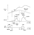
- the BTDC premixed combustion in the present invention is a combustion that realizes early ignition (early injection) as described below. Therefore, even if a decrease in the high-temperature oxidation reaction rate or an ignition delay occurs, there is a margin to TDC. The margin can absorb the decrease in the high-temperature oxidation reaction rate and the ignition delay. Even if the ignition delay occurs, the in-cylinder gas temperature continues to rise (see FIG. 5), and the ignitability of the combustion field is improved. As a result, the ignition timing of diffusion combustion is stabilized and combustion with high robustness can be realized. Moreover, combustion noise can be suppressed.
- the fuel injection (sub-injection) that starts the low-temperature oxidation reaction when the compressed gas temperature reaches 750K in the compression process is an early injection before the compression top dead center (for example, BTDC 40 to 25 ° CA).
- the compression top dead center for example, BTDC 40 to 25 ° CA.
- Premixed combustion is slow combustion that follows a gradual temperature rise. As a result, it is possible to realize combustion in which the amount of NOx generated, the amount of smoke generated, and the combustion noise are suppressed.
- loss (negative work amount) during the compression stroke can be reduced.
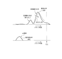
- the low-temperature oxidation reaction is hardly affected by the change in the fuel composition because it starts combustion at a temperature-controlled rate (see FIG. 6). Therefore, the ignition field for the high-temperature oxidation reaction can always be created stably by the low-temperature oxidation reaction, and there is an advantage that it is hardly affected by changes in the fuel composition.
- the required amount of the low-temperature oxidation reaction component is, for example, 1.5 to 2 mm 3 . Further, since the content of the low temperature oxidation reaction component in the light oil fuel is about 15%, the fuel injection amount (sub injection amount) required for the low temperature oxidation reaction is 10 to 13 mm 3 .
- the fuel injection amount can ensure such a low-temperature oxidation reaction amount
- the high-temperature oxidation reaction component when the high-temperature oxidation reaction component is small (when the fuel injection amount of the sub-injection is small), the in-cylinder gas temperature reaches 900K.
- the fuel is overdispersed, and the premixed combustion amount (premixed combustion amount for satisfying the required ignition temperature (for example, 1000 K) of diffusion combustion) before TDC cannot be secured.
- the high-temperature oxidation reaction is decisive for the amount of radicals and hydrogen peroxide that promote H desorption in the vicinity of hydrocarbon molecules, so the high-temperature oxidation reaction requires a certain fuel density (spatial density).
- the fuel injection amount is small, it becomes impossible to generate a spray distribution with a density sufficient for radicals, hydrogen peroxide, and oxygen by 900K, and the BTDC premixed combustion amount cannot be secured. Therefore, it is necessary to define the lower limit amount of the fuel injection amount of the sub-injection in consideration of such points. Further, in the present invention, in order to ensure a premixed combustion amount necessary until TDC, a large amount of fuel equal to or greater than the lower limit amount is quickly and rapidly injected.
- the lower limit amount of the fuel injection amount of the sub-injection for example, in order to secure the necessary amount of the low-temperature oxidation reaction component and the premixed combustion amount using the operating state (engine speed and engine torque) of the internal combustion engine as parameters. What is necessary is just to obtain
- the amount of the low temperature oxidation reaction component contained in the fuel is also increased, so that the period of the low temperature oxidation reaction becomes longer. If the low-temperature oxidation reaction period becomes long and the low-temperature oxidation reaction cannot be completed before reaching the high-temperature oxidation reaction start temperature (900K), the high-temperature oxidation reaction is combined. In such a situation (a situation where the low-temperature oxidation reaction and the high-temperature oxidation reaction are combined), combustion becomes a problem because combustion becomes steep.
- the upper limit amount of the fuel injection amount is taken into consideration by the operation state (engine speed and engine torque) of the internal combustion engine, taking into account the combustion noise. You may ask for it.
- the fuel injection amount of the sub-injection is set to a fuel amount equal to or greater than the above lower limit amount (the upper limit is limited by the above upper limit amount) and performing the above-described early mass single injection, the low temperature oxidation reaction and the high temperature oxidation reaction And the above-described premixed combustion with slow combustion and reduced combustion noise can be realized.
- the injection timing of the secondary injection may be a timing at which the fuel injected by the secondary injection ignites (oxidation reaction start) when the in-cylinder gas temperature reaches 750K (low temperature oxidation reaction start temperature). More preferably, the time when all the fuel spray capable of securing the necessary amount of the low-temperature oxidation reaction is vaporized before the in-cylinder gas temperature reaches 750K is good.
- the fuel injection (sub-injection) for starting the low-temperature oxidation reaction when the compressed gas temperature reaches 750K is the BTDC early injection, and the more advanced the injection timing, the wider the space.
- unburned HC Hydrocarbons
- the advance guard value may be determined by experiment / simulation in consideration of the amount of unburned HC generated.
- diffusion combustion by main injection when importance is attached to emission reduction and the generation amount of NOx and smoke is suppressed, diffusion combustion by main injection may be retarded and the fuel injection amount of main injection may be reduced.
- NOx is retarded by retarding the injection timing of the main injection for diffusion combustion with respect to TDC and retarding diffusion combustion. Limit the volume to the required value.
- it is necessary to retard the injection timing of the main injection for diffusion combustion to reduce the fuel injection amount of the diffusion combustion injection.
- the present invention in order to suppress a decrease in torque due to a retard angle (diffuse combustion retard angle) with respect to the TDC of main injection and to suppress the occurrence of smoke due to a reduction in oxygen concentration, according to the required amount of NOx.
- the amount of fuel combustible by the retarded diffusion combustion (the upper limit fuel amount at which smoke is not generated by the retarded diffusion combustion) is the fuel injection amount of the main injection
- the upper limit of the fuel injection amount of the main injection is not excessively injected, so that the occurrence of smoke in diffusion combustion can be suppressed.
- the fuel injection amount of the sub-injection for premixed combustion is determined based on the fuel injection amount and the total fuel injection amount of the main injection that performs the retardation (for example, the fuel injection amount of the main injection by the retardation)
- the fuel injection amount of the secondary injection is increased by the amount reduced.)
- the upper limit amount of the fuel injection amount of the sub-injection is limited in consideration of this point. In this case, when the fuel injection amount of the sub-injection is larger than the upper limit amount, the surplus fuel amount is injected (after injection) after the main injection for diffusion combustion to secure the generated torque.
- the present invention it is possible to execute a main injection that performs combustion mainly using diffusion combustion and a sub-injection that is performed prior to the main injection and that mainly performs premixed combustion.
- a fuel injection control device for a compression-ignition internal combustion engine the premixed combustion by sub-injection is separated into a low temperature oxidation reaction and a high temperature oxidation reaction, so the premix combustion period can be lengthened and premixing A sufficient amount of combustion can be secured.
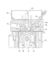
- FIG. 1 is a schematic configuration diagram of an engine to which the present invention is applied and a control system thereof. It is sectional drawing which shows the combustion chamber of a diesel engine, and its peripheral part. It is a block diagram which shows the structure of control systems, such as ECU. It is a schematic diagram of the intake / exhaust system and the combustion chamber for explaining the outline of the combustion mode in the combustion chamber. Change in heat generation rate (heat generation amount per unit rotation angle of crankshaft), change in fuel injection rate (fuel injection amount per unit rotation angle of crankshaft), and in-cylinder gas temperature during the compression / expansion stroke It is a wave form diagram which shows each change of. It is a wave form diagram which shows the change of the heat release rate when a fuel composition changes.
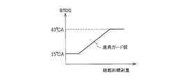
- FIG. 6 also shows a waveform diagram of the fuel injection rate. It is a PV diagram of a diesel engine to which the present invention is applied. It is a figure which shows the setting map of the advance angle guard value of sub injection. It is a graph which shows the relationship between the ignition temperature of the air-fuel
- FIG. 1 is a schematic configuration diagram of the engine 1 and its control system.
- FIG. 2 is a cross-sectional view showing the combustion chamber 3 of the diesel engine and its periphery.
- the engine 1 of this example is configured as a diesel engine system having a fuel supply system 2, a combustion chamber 3, an intake system 6, an exhaust system 7 and the like as main parts.
- the fuel supply system 2 includes a supply pump 21, a common rail 22, an injector (fuel injection valve) 23, a shutoff valve 24, a fuel addition valve 26, an engine fuel passage 27, an addition fuel passage 28, and the like.
- the supply pump 21 pumps fuel from the fuel tank, makes the pumped fuel high pressure, and supplies it to the common rail 22 via the engine fuel passage 27.
- the common rail 22 has a function as a pressure accumulation chamber that holds (accumulates) the high-pressure fuel supplied from the supply pump 21 at a predetermined pressure, and distributes the accumulated fuel to the injectors 23.
- the injector 23 includes a piezoelectric element (piezo element) therein, and is configured by a piezo injector that is appropriately opened to supply fuel into the combustion chamber 3. Details of the fuel injection control from the injector 23 will be described later.
- the supply pump 21 supplies a part of the fuel pumped up from the fuel tank to the fuel addition valve 26 via the addition fuel passage 28.
- the added fuel passage 28 is provided with the shutoff valve 24 for shutting off the added fuel passage 28 and stopping fuel addition in an emergency.
- the fuel addition valve 26 is configured so that the fuel addition amount to the exhaust system 7 becomes a target addition amount (addition amount that makes the exhaust A / F become the target A / F) by an addition control operation by the ECU 100 described later.
- it is constituted by an electronically controlled on-off valve whose valve opening timing is controlled so that the fuel addition timing becomes a predetermined timing. That is, a desired fuel is injected and supplied from the fuel addition valve 26 to the exhaust system 7 (from the exhaust port 71 to the exhaust manifold 72) at an appropriate timing.
- the intake system 6 includes an intake manifold 63 connected to an intake port 15a formed in the cylinder head 15 (see FIG. 2), and an intake pipe 64 constituting an intake passage is connected to the intake manifold 63.
- an air cleaner 65, an air flow meter 43, and a throttle valve (intake throttle valve) 62 are arranged in this intake passage sequentially from the upstream side.
- the air flow meter 43 outputs an electrical signal corresponding to the amount of air flowing into the intake passage via the air cleaner 65.
- the intake system 6 is provided with a swirl control valve (swirl speed variable mechanism) 66 for making the swirl flow (horizontal swirl flow) in the combustion chamber 3 variable.
- a swirl control valve swirl speed variable mechanism
- the intake port 15a two systems of a normal port and a swirl port are provided for each cylinder. Of these, a normal valve 15a shown in FIG. A swirl control valve 66 is arranged.
- An actuator (not shown) is connected to the swirl control valve 66, and the flow rate of air passing through the normal port 15a can be changed according to the opening of the swirl control valve 66 adjusted by driving the actuator. Yes.
- the larger the opening of the swirl control valve 66 the greater the amount of air taken into the cylinder from the normal port 15a.
- the swirl generated by the swirl port becomes relatively weak, and the inside of the cylinder becomes low swirl (a state where the swirl speed is low).
- the smaller the opening of the swirl control valve 66 the smaller the amount of air drawn into the cylinder from the normal port 15a. For this reason, the swirl generated by the swirl port is relatively strengthened, and the inside of the cylinder becomes a high swirl (a state where the swirl speed is high).
- the exhaust system 7 includes an exhaust manifold 72 connected to an exhaust port 71 formed in the cylinder head 15, and exhaust pipes 73 and 74 constituting an exhaust passage are connected to the exhaust manifold 72. .
- a maniverter (exhaust gas purification device) 77 including a NOx storage catalyst (NSR catalyst: NOx Storage Reduction catalyst) 75 and a DPNR catalyst (Diesel Particle-NOx Reduction catalyst) 76 is disposed in the exhaust passage. Yes.
- NSR catalyst 75 and the DPNR catalyst 76 will be described.
- the NSR catalyst 75 is an NOx storage reduction catalyst.
- alumina Al 2 O 3
- potassium (K) sodium (Na), lithium (Li), cesium (Cs) is supported on the carrier, for example.
- Alkali metals such as barium (Ba) and calcium (Ca)
- rare earths such as lanthanum (La) and yttrium (Y)
- noble metals such as platinum (Pt) are supported. It becomes the composition.
- the NSR catalyst 75 occludes NOx in a state where a large amount of oxygen is present in the exhaust gas, has a low oxygen concentration in the exhaust gas, and a large amount of reducing component (for example, an unburned component (HC) of the fuel).
- reducing component for example, an unburned component (HC) of the fuel.
- NOx is reduced to NO 2 or NO and released.
- NO NOx released as NO 2 or NO the N 2 is further reduced due to quickly reacting with HC or CO in the exhaust.
- HC and CO are oxidized to H 2 O and CO 2 by reducing NO 2 and NO. That is, by appropriately adjusting the oxygen concentration and HC component in the exhaust gas introduced into the NSR catalyst 75, HC, CO, and NOx in the exhaust gas can be purified.
- the oxygen concentration and HC component in the exhaust gas can be adjusted by the fuel addition operation from the fuel addition valve 26.
- the DPNR catalyst 76 is, for example, a NOx occlusion reduction catalyst supported on a porous ceramic structure, and PM in the exhaust gas is collected when passing through the porous wall. Further, when the air-fuel ratio of the exhaust gas is lean, NOx in the exhaust gas is stored in the NOx storage reduction catalyst, and when the air-fuel ratio becomes rich, the stored NOx is reduced and released. Further, the DPNR catalyst 76 carries a catalyst that oxidizes and burns the collected PM (for example, an oxidation catalyst mainly composed of a noble metal such as platinum).
- a cylinder block 11 constituting a part of the engine body is formed with a cylindrical cylinder bore 12 for each cylinder (four cylinders), and a piston 13 is formed inside each cylinder bore 12. Is accommodated so as to be slidable in the vertical direction.
- the combustion chamber 3 is formed above the top surface 13 a of the piston 13. That is, the combustion chamber 3 is defined by the lower surface of the cylinder head 15 attached to the upper part of the cylinder block 11 via the gasket 14, the inner wall surface of the cylinder bore 12, and the top surface 13 a of the piston 13.
- a cavity (concave portion) 13 b is formed in a substantially central portion of the top surface 13 a of the piston 13, and this cavity 13 b also constitutes a part of the combustion chamber 3.
- the concave dimension is small in the central portion (on the cylinder center line P), and the concave dimension is increased toward the outer peripheral side. That is, as shown in FIG. 2, when the piston 13 is in the vicinity of the compression top dead center, the combustion chamber 3 formed by the cavity 13b is a narrow space with a relatively small volume in the central portion, and on the outer peripheral side. The structure is such that the space is gradually expanded toward the expansion space.
- the piston 13 has a small end portion 18a of a connecting rod 18 connected by a piston pin 13c, and a large end portion of the connecting rod 18 is connected to a crankshaft which is an engine output shaft.
- a glow plug 19 is disposed toward the combustion chamber 3.
- the glow plug 19 functions as a start-up assisting device that is heated red when an electric current is applied immediately before the engine 1 is started and a part of the fuel spray is blown onto the glow plug 19 to promote ignition and combustion.
- the cylinder head 15 is formed with an intake port 15a (normal port and swirl port) for introducing air into the combustion chamber 3 and an exhaust port 71 for discharging exhaust gas from the combustion chamber 3, respectively.
- An intake valve 16 for opening and closing the port 15a and an exhaust valve 17 for opening and closing the exhaust port 71 are provided.
- the intake valve 16 and the exhaust valve 17 are disposed to face each other with the cylinder center line P interposed therebetween. That is, the engine 1 of this example is configured as a cross flow type.
- the cylinder head 15 is provided with the injector 23 that directly injects fuel into the combustion chamber 3.
- the injector 23 is disposed at a substantially upper center of the combustion chamber 3 in a standing posture along the cylinder center line P, and injects fuel introduced from the common rail 22 toward the combustion chamber 3 at a predetermined timing. It has become.
- the engine 1 is provided with a supercharger (turbocharger) 5.
- the turbocharger 5 includes a turbine wheel 52 and a compressor impeller 53 that are connected via a turbine shaft 51.
- the compressor impeller 53 is arranged facing the inside of the intake pipe 64, and the turbine wheel 52 is arranged facing the inside of the exhaust pipe 73. Therefore, the turbocharger 5 performs a so-called supercharging operation in which the compressor impeller 53 is rotated using the exhaust flow (exhaust pressure) received by the turbine wheel 52 to increase the intake pressure.
- the turbocharger 5 in this example is a variable nozzle type turbocharger (VNT), and a variable nozzle vane mechanism 54 is provided on the turbine wheel 52 side, and an opening degree (VN opening degree) of the variable nozzle vane mechanism 54 is adjusted. By doing so, the supercharging pressure of the engine 1 can be adjusted.
- VNT variable nozzle type turbocharger
- VN opening degree opening degree
- the intake pipe 64 of the intake system 6 is provided with an intercooler 61 for forcibly cooling the intake air whose temperature has been raised by supercharging in the turbocharger 5.
- the throttle valve 62 is provided further downstream than the intercooler 61.
- the throttle valve 62 is an electronically controlled on-off valve whose opening degree can be adjusted in a stepless manner. The throttle air flow area of the intake air is reduced under a predetermined condition, and the supply amount of the intake air is adjusted (reduced). ) Function.
- the engine 1 is provided with an exhaust gas recirculation passage (EGR passage) 8 that connects the intake system 6 and the exhaust system 7.
- the EGR passage 8 is configured to reduce the combustion temperature by recirculating a part of the exhaust gas to the intake system 6 and supplying it again to the combustion chamber 3, thereby reducing the amount of NOx generated.
- the EGR passage 8 is opened and closed steplessly by electronic control, and the exhaust gas passing through the EGR passage 8 (recirculating) is cooled by an EGR valve 81 that can freely adjust the exhaust flow rate flowing through the passage.
- An EGR cooler 82 is provided.
- the EGR passage 8, the EGR valve 81, the EGR cooler 82, and the like constitute an EGR device (exhaust gas recirculation device).
- the air flow meter 43 outputs a detection signal corresponding to the flow rate (intake air amount) of the intake air upstream of the throttle valve 62 in the intake system 6.
- the intake air temperature sensor 49 is disposed in the intake manifold 63 and outputs a detection signal corresponding to the temperature of the intake air.
- the intake pressure sensor 48 is disposed in the intake manifold 63 and outputs a detection signal corresponding to the intake air pressure.
- the A / F (air-fuel ratio) sensor 44 outputs a detection signal that continuously changes in accordance with the oxygen concentration in the exhaust gas downstream of the manipulator 77 of the exhaust system 7.
- the exhaust temperature sensor 45 outputs a detection signal corresponding to the temperature of the exhaust gas (exhaust temperature) downstream of the manipulator 77 of the exhaust system 7.
- the rail pressure sensor 41 outputs a detection signal corresponding to the fuel pressure stored in the common rail 22 (hereinafter also referred to as fuel pressure).
- the throttle opening sensor 42 detects the opening of the throttle valve 62.
- the ECU (Electronic Control Unit) 100 includes a CPU (Central Processing Unit) 101, a ROM (Read Only Memory) 102, a RAM (Random Access Memory) 103, a backup RAM 104, and the like.
- the ROM 102 stores various control programs, maps that are referred to when the various control programs are executed, and the like.
- the CPU 101 executes various arithmetic processes based on various control programs and maps stored in the ROM 102.
- the RAM 103 is a memory that temporarily stores calculation results in the CPU 101, data input from each sensor, and the like.
- the backup RAM 104 is a non-volatile memory that stores data to be saved when the engine 1 is stopped, for example.
- the CPU 101, the ROM 102, the RAM 103, and the backup RAM 104 are connected to each other via the bus 107 and to the input interface 105 and the output interface 106.
- the input interface 105 is connected to the rail pressure sensor 41, the throttle opening sensor 42, the air flow meter 43, the A / F sensor 44, the exhaust temperature sensor 45, the intake pressure sensor 48, and the intake temperature sensor 49. Further, the input interface 105 includes a water temperature sensor 46 that outputs a detection signal corresponding to the cooling water temperature of the engine 1, an accelerator opening sensor 47 that outputs a detection signal corresponding to the depression amount of the accelerator pedal, and the engine 1. A crank position sensor 40 that outputs a detection signal (pulse) each time the output shaft (crankshaft) rotates by a certain angle is connected.
- the supply interface 21, the injector 23, the fuel addition valve 26, the throttle valve 62, the variable nozzle vane mechanism 54, the EGR valve 81, and the like are connected to the output interface 106.
- the ECU 100 executes various controls of the engine 1 based on the outputs of the various sensors described above.
- the ECU 100 executes fuel injection control of the injector 23.
- fuel injection control of the injector 23 sub-injection (pilot injection) and main injection (main injection) are executed.
- combustion by sub-injection is premixed combustion main combustion (also referred to as premixed combustion), and main injection combustion is diffusion combustion main combustion (also referred to as diffusion combustion).
- premixed combustion main combustion also referred to as premixed combustion
- diffusion combustion main combustion also referred to as diffusion combustion.
- the main injection is an injection operation (torque generation fuel supply operation) for generating torque of the engine 1.
- the injection amount in the main injection is basically determined so as to obtain the required torque according to the operating state such as the engine speed, the accelerator operation amount, the coolant temperature, the intake air temperature, and the like. For example, the higher the engine speed (the engine speed calculated based on the output signal of the crank position sensor 40), the greater the accelerator operation amount (the amount of depression of the accelerator pedal detected by the accelerator opening sensor 47). As the accelerator opening becomes larger, the required torque value of the engine 1 is obtained higher, and accordingly, the fuel injection amount in the main injection is set larger.
- the sub-injection is an operation for injecting fuel prior to the main injection from the injector 23. Details of this sub-injection will be described later.
- the main injection is performed in a state in which the preheating in the combustion chamber 3 (inside the cylinder) is sufficiently performed by the premixed combustion in the sub injection, so that the combustion is performed in the main injection.
- the fuel injected into the chamber 3 is immediately exposed to a temperature environment equal to or higher than the self-ignition temperature, and pyrolysis proceeds. After the injection, combustion starts immediately.
- fuel ignition delays in diesel engines include physical delays and chemical delays.
- the physical delay is the time required for evaporation / mixing of the fuel droplets and depends on the gas temperature of the combustion field.
- the chemical delay is the time required for chemical bonding / decomposition of fuel vapor and oxidation heat generation.
- the physical delay can be minimized, and as a result, the ignition delay can be minimized. . Therefore, as a combustion mode of the fuel injected by the main injection, premixed combustion is hardly performed, and most of it is diffusion combustion.
- the injection timing and fuel injection amount of the main injection By adjusting the injection timing and fuel injection amount of the main injection, the ignition timing in diffusion combustion, the rate of change of the heat generation rate [J / CA] (the gradient of the heat generation rate waveform), and the peak of the heat generation rate It becomes possible to control the time when the combustion center of gravity is reached.
- the amount of NOx generated can be suppressed by retarding the injection timing of the main injection for diffusion combustion with respect to TDC and retarding diffusion combustion (retarding the combustion center of gravity of diffusion combustion).
- After injection is an injection operation for increasing the exhaust gas temperature. Specifically, after injection is performed at a timing at which most of the combustion energy of the supplied fuel is obtained as thermal energy of the exhaust gas without being converted into torque of the engine 1.
- the post-injection is an injection operation for directly introducing fuel into the exhaust system 7 to increase the temperature of the manipulator 77. For example, when the accumulated amount of PM trapped in the DPNR catalyst 76 exceeds a predetermined amount (for example, detected by detecting a differential pressure before and after the manipulator 77), post injection is performed. .
- the fuel injection pressure when executing the fuel injection is determined by the internal pressure of the common rail 22.
- the target value of the fuel pressure supplied from the common rail 22 to the injector 23, that is, the target rail pressure increases as the engine load (engine load) increases and as the engine speed (engine speed) increases. It is supposed to be expensive. That is, when the engine load is high, the amount of air sucked into the combustion chamber 3 is large. Therefore, a large amount of fuel must be injected from the injector 23 into the combustion chamber 3, and therefore the injection from the injector 23 is performed.
- the pressure needs to be high.
- the target rail pressure is generally set based on the engine load and the engine speed.
- the target rail pressure is set according to a fuel pressure setting map stored in the ROM 102, for example. That is, by determining the fuel pressure according to this fuel pressure setting map, the valve opening period (injection rate waveform) of the injector 23 is controlled, and the fuel injection amount during the valve opening period can be defined.
- the fuel pressure is adjusted between 30 MPa and 200 MPa according to the engine load and the like. That is, as a control range of the fuel pressure, the lower limit value is 30 MPa and the upper limit value is 200 MPa.
- the optimum value of the fuel injection amount varies depending on the temperature conditions of the engine 1 and the intake air.
- the ECU 100 sets the fuel discharge amount of the supply pump 21 so that the common rail pressure becomes equal to the target rail pressure set based on the engine operating state, that is, the fuel injection pressure matches the target injection pressure. Weigh out. Further, the ECU 100 determines the fuel injection amount and the fuel injection mode based on the engine operating state.
- the ECU 100 calculates the engine rotation speed based on the output signal of the crank position sensor 40, and obtains the depression amount (accelerator opening) of the accelerator pedal based on the output signal of the accelerator opening sensor 47, Based on the engine speed and the accelerator opening, the total fuel injection amount (the sum of the injection amount in the secondary injection and the injection amount in the main injection) is determined.
- the ECU 100 controls the opening degree of the EGR valve 81 according to the operating state of the engine 1 and adjusts the exhaust gas recirculation amount (EGR amount) toward the intake manifold 63.
- the EGR amount is set according to an EGR map stored in advance in the ROM 102.
- this EGR map is a map for determining the EGR amount (EGR rate) using the engine speed and the engine load as parameters. Note that this EGR map is created in advance by experiments, simulations, or the like. That is, by applying the engine speed calculated based on the output signal of the crank position sensor 40 and the opening of the throttle valve 62 (corresponding to the engine load) detected by the throttle opening sensor 42 to the EGR map. An EGR amount (opening degree of the EGR valve 81) is obtained.
- the fuel injection control device for an internal combustion engine of the present invention is realized by the program executed by the ECU 100 described above.
- FIG. 4 gas (air) is sucked into one cylinder of the engine 1 through the intake manifold 63 and the intake port 15 a, and combustion is performed by fuel injection from the injector 23 into the combustion chamber 3.
- FIG. 6 is a diagram schematically showing how the subsequent gas is discharged to the exhaust manifold 72 through the exhaust port 71.
- the gas sucked into the cylinder includes fresh air sucked from the intake pipe 64 through the throttle valve 62 and from the EGR passage 8 when the EGR valve 81 is opened.
- Inhaled EGR gas is included.
- the ratio of the amount of EGR gas (that is, the EGR rate) to the sum of the amount of fresh air (mass) to be sucked and the amount of EGR gas (mass) to be sucked is appropriately controlled by the ECU 100 according to the operating state. It changes according to the opening degree of 81.
- the fresh air and EGR gas sucked into the cylinder (combustion chamber 3) in this way are lowered as the piston 13 (not shown in FIG. 4) descends via the intake valve 16 which is opened in the intake stroke. Then, it is sucked into the cylinder and becomes in-cylinder gas.
- This in-cylinder gas is sealed in the cylinder (inside the combustion chamber 3) by closing the intake valve 16 when the valve is closed according to the operating state of the engine 1 (in-cylinder gas confinement state).
- the piston 13 is compressed as it rises.
- the injector 23 is opened for a predetermined time by the injection amount control by the ECU 100 described above, so that the fuel is directly injected into the combustion chamber 3. Specifically, the sub-injection is executed before the piston 13 reaches the top dead center, and after the fuel injection is temporarily stopped, the piston 13 reaches the vicinity of the top dead center after a predetermined interval (or The main injection is executed after compression top dead center).
- the low-temperature oxidation reaction mainly consists of a fuel having a straight single bond composition such as a normal back end, and the order of low-temperature autoignition is [straight chain]> [side chain]> [cyclic], [single crystal]> [Double bond]> [triple bond].
- the normal paraffinic hydrocarbon contained in the light oil fuel is the main component of the low temperature oxidation reactivity, and the longer the straight chain length, the greater the low temperature oxidation reaction.
- the high-temperature oxidation reaction depends on the reaction in which the straight chain hydrocarbon of the polymer becomes a radical having an unpaired electron, the radical accumulated in the reaction that generates hydrogen peroxide, and the density of peroxidation (H 2 O 2 ). The starting temperature and amount of reaction are determined.
- the high-temperature oxidation reaction is decisive for the amount of radicals and hydrogen peroxide that promote H desorption in the vicinity of hydrocarbon molecules, so the high-temperature oxidation reaction has a predetermined fuel density (spatial density). Is required. Therefore, it is necessary to generate a spray distribution with a density sufficient for radicals, hydrogen peroxide and oxygen by the high temperature oxidation start temperature, and it is necessary to secure a fuel injection amount (premixed combustion amount) that satisfies this. There is.
- the sub-injection is set to early mass single injection.
- BTDC early injection compression ratio 15: BTDC 40 to 25 ° CA
- BTDC 25 ° CA wide-area fuel injection into a wider space is achieved, and the combustion field is reduced in temperature and pressure.
- the premixed combustion by the sub-injection becomes a slow combustion that follows a moderate temperature rise. As a result, it is possible to realize combustion while suppressing the generation amount of NOx and the generation amount of smoke. Furthermore, since the premix combustion before the compression top dead center is slowed down, loss (negative work amount) during the compression stroke can be reduced.
- the premix combustion period can be extended and the premix combustion amount can be maximized.
- the premix combustion period can be extended and the premix combustion amount can be maximized.
- the low-temperature oxidation reaction is hardly affected by the change in the fuel composition because it starts combustion at a temperature-controlled rate (see FIG. 6). Therefore, since the ignition field for the high temperature oxidation reaction can be stably created by the low temperature oxidation reaction, there is an advantage that it is difficult to be affected by changes in the fuel composition.
- the sub-injection is performed as a large-scale single injection at an early stage (for example, BTDC 40 ° CA), and the premixed combustion by the subinjection and the diffusion combustion by the main injection are separated, and further, the premixed combustion is performed.
- the center of gravity of the premixed combustion (the center of gravity of the high temperature oxidation reaction region) can be made around BTDC 10 ° CA.
- the volume change per crank angle of 1 ° CA is small and can be regarded as almost constant.
- the in-cylinder gas pressure can be increased by the combustion, so that the isobaric combustion region is extended to the high pressure side as shown in FIG. Can do.
- isobaric combustion is generated, and the pressure of the isobaric combustion is increased, so that the area on the PV line (area surrounded by the thermal cycle), that is, the work amount, is the case of normal control ( Compared with the broken line in FIG.
- multi-stage divided injection for example, three-stage divided injection
- overdispersed spray in the space increases, causing a problem that unburned HC rapidly increases.
- the injection period of the multistage divided injection is long. , Diffusion combustion is likely to occur.
- the injection timing of the second stage injection (2nd injection) or the third stage injection (3rd injection) is later than 900K
- the fuel injected by the 2nd injection or 3rd injection burns at once. Therefore, diffusion combustion may occur, and the diffusion combustion may retreat to the region after compression top dead center (ATDC). From such a point, it is necessary to adopt the above-described early mass single injection for the sub-injection.
- the required amount of the low-temperature oxidation reaction component is, for example, 1.5 to 2 mm 3 . Further, since the content of the low temperature oxidation reaction component in the light oil fuel is about 15%, the fuel injection amount (sub injection amount) required for the low temperature oxidation reaction is 10 to 13 mm 3 .
- the fuel injection amount can ensure such a low-temperature oxidation reaction amount
- the high-temperature oxidation reaction component when the high-temperature oxidation reaction component is small (when the fuel injection amount of the sub-injection is small), the in-cylinder gas temperature reaches 900K.
- the fuel is overdispersed, and the premixed combustion amount (premixed combustion amount for satisfying the required ignition temperature (for example, 1000 K) of diffusion combustion) before TDC cannot be secured. That is, as described above, the high-temperature oxidation reaction is decisive for the amount of radicals and hydrogen peroxide that promote H desorption in the vicinity of the hydrocarbon molecules.
- the fuel injection amount (necessary for securing the necessary amount of the low-temperature oxidation reaction component and the premixed combustion amount) using the operating state (engine speed and required torque) of the engine 1 as parameters.
- the lower limit amount is obtained by experiments and simulations.
- the amount of the low temperature oxidation reaction component contained in the fuel is also increased, so that the period of the low temperature oxidation reaction becomes longer. If the low-temperature oxidation reaction period becomes long and the low-temperature oxidation reaction cannot be completed before reaching the high-temperature oxidation reaction start temperature (900K), the high-temperature oxidation reaction is combined. In such a situation (low temperature oxidation reaction and high temperature oxidation reaction are combined), combustion becomes sharp and combustion noise becomes a problem. Also, if the fuel injection amount of the secondary injection is increased, the high-temperature oxidation reaction component increases and the density (spray density) increases, so the high-temperature oxidation reaction rate becomes rapid and combustion rapidly evolves. Sound is a problem. From such a point, it is necessary to define the upper limit amount of the fuel injection amount of the sub-injection.
- the operating state (engine speed and required torque) of the engine 1 is used as a parameter, and the upper limit amount of the fuel injection amount is obtained by experiment / simulation in consideration of the combustion noise.
- the fuel injection pattern (injection timing / fuel injection amount of sub-injection for premixed combustion and injection timing / fuel injection amount of main injection for diffusion combustion) is adjusted to execute fuel injection from the injector 23
- a specific control procedure in this case will be described with reference to FIG.
- the fuel injection control ([S1] to [S6] and the like) described below is repeatedly executed by the ECU 100 for each predetermined crank angle (each cylinder). Specifically, for example, when one cylinder is described, every time a combustion stroke of the cylinder is executed, fuel injection control is executed prior to the combustion stroke.
- (Reference crank angle Ainj) For a target engine 1 (for example, a diesel engine having a compression ratio of 15), a bench test or a simulation is performed, and a compressed gas obtained by adding (offset) the motoring temperature waveform shown in FIG. Collect the estimated temperature waveform. From the collected compressed gas temperature estimation waveform, a crank angle [° CA] at which the in-cylinder gas temperature (compressed gas temperature) becomes 750K is obtained. The crank angle of 750K collected in this way is set as a base point (reference crank angle Ainj) for controlling the sub-injection at a temperature-controlled rate. The reference crank angle Ainj is acquired and mapped for each operating state (for example, for each grid point of the operating state map using the engine speed and the required torque as parameters) in the above processing, and stored in the ROM 102 of the ECU 100.
- the reference crank angle Ainj is acquired and mapped for each operating state (for example, for each grid point of the operating state map using the engine speed and the required torque as parameters)
- a retard value of the injection timing (injection start timing) of the main injection with respect to the TDC is determined with reference to the map based on the required NOx amount [g / h] required for the engine 1.
- This retard value map is a map for setting the retard value of the injection timing of the main injection with respect to the TDC using the required NOx amount as a parameter, and is created in advance by experiments, simulations, etc. For example, the ROM 102 of the ECU 100 Is remembered. In this retard value map, the retard value of the injection timing (injection start timing) of the main injection is set to be larger as the required NOx amount is smaller. However, if the delay angle of the diffusion combustion by the main injection for diffusion combustion is too large, misfire occurs, and therefore the upper limit of the delay side of the main injection is limited in order to suppress this.
- the retard angle of the main injection may be limited by setting the injection timing such that the combustion center of gravity of the diffusion combustion by the main injection becomes, for example, ATDC 20 ° CA.
- the retard angle of the main injection may be limited by setting the injection timing such that the combustion center of gravity of the fuel by the main injection becomes, for example, ATDC 15 ° CA, as the retard guard value.
- the fuel injection amount of the main injection is a fuel amount that emphasizes emission reduction, and is smaller than the fuel amount in the case of fuel injection that emphasizes performance (emphasis on engine torque, etc.). .
- the required torque is a satisfactory fuel injection amount.
- the injection period (injection start time to injection end time) of the main injection is calculated based on the fuel injection amount of the main injection and the injection characteristics (injection amount per unit time, etc.) of the injector 23. Then, the injection end timing of the main injection shown in FIG. 5 is determined based on the fuel period of the main injection and the injection timing (injection start timing) of the main injection.
- the upper limit fuel amount map used in the processing of [S3] uses the retard value of the injection timing of the main injection with respect to TDC as a parameter, and the upper limit value of the fuel amount that does not cause smoke in diffusion combustion (can be combusted by retarded diffusion combustion). (Fuel amount) is obtained in advance by experiments, simulations, etc., and a value (upper limit fuel amount) adapted based on the result is mapped, and stored in the ROM 102 of the ECU 100, for example. In this upper limit fuel amount map, the upper limit fuel amount in the diffusion combustion is set to be smaller as the retardation value of the injection timing of the main injection is larger.
- the fuel injection amount of the sub-injection calculated in the process of [S4] ([total fuel injection amount] ⁇ [fuel injection amount of main injection]) is to secure and predict the necessary amount of the low-temperature oxidation reaction component described above.
- the fuel amount sufficiently satisfies the fuel injection amount (lower limit amount) necessary for securing the mixed combustion amount (securing 1000K or more at the time of main injection), and is the fuel amount capable of realizing the above-mentioned early mass single injection.
- crank angle Ainj crank angle that becomes 750K
- the reference crank angle Ainj (crank angle that becomes 750K) is obtained with reference to a map based on the current operation state (for example, engine speed and required torque).
- the injection end timing of the sub-injection shown in FIG. 5 is determined.
- the spray of the sub-injection fuel injection amount (a fuel amount that can secure the low-temperature oxidation reaction required amount) obtained in the process of [S4] reaches the reference crank angle Ainj (750K).
- the injection period (injection start time to injection end time) of the sub-injection is calculated based on the fuel injection amount of the sub-injection and the injection characteristics (injection amount per unit time, etc.) of the injector 23.
- the injection start timing (calculated value) of the sub-injection is retarded or advanced than the following advance guard value, and the injection start timing of the sub-injection is the advance guard value If it is more retarded, the fuel injection pattern as shown in FIG. 5 is determined using the injection start timing and injection end timing of the sub-injection calculated in the above process as they are.
- the sub-injection injection timing is set to the advance guard value in order to further slow down the premixed combustion by the sub-injection. You may make it advance to.
- the injection start timing (calculated value) of the secondary injection is on the advance side of the advance guard value
- the injection timing of the secondary injection is limited to the advance guard value.
- the generated torque is secured by injecting the sub-injection with the after-injection after the main injection. To do.
- the advance angle guard value is obtained with reference to the map of FIG. 8 based on the total fuel injection amount of the secondary injection.
- the map in FIG. 8 is a map of values obtained by empirically adapting the advance angle guard value in advance through experiments, simulations, etc., taking the total fuel injection amount of sub-injection as a parameter and considering the amount of unburned HC generated. For example, it is stored in the ROM 102 of the ECU 100.
- Fuel injection from the injector 23 is executed based on the fuel injection pattern determined as described above (subject injection start timing / injection end timing and main injection start timing / injection end timing). .
- the combustion of the heat release rate waveform as shown in FIG. 5, that is, the combustion center of gravity of premixed combustion and the combustion center of gravity of diffusion combustion are separated, and the premixed combustion is performed at a low temperature oxidation reaction. Combustion separated into a high-temperature oxidation reaction can be realized.
- the premixed combustion and the diffusion combustion are separated, and the premixed combustion is further subjected to low-temperature oxidation. Since fuel injection is controlled so as to be separated into a reaction and a high-temperature oxidation reaction, premixed combustion can be made slow. As a result, the premix combustion period until diffusion combustion can be lengthened, and the preheat amount and the premix combustion amount can be sufficiently secured. As a result, the ignition timing of diffusion combustion by main injection is stabilized, and combustion with high robustness can be realized.
- the sub-injection is set to early injection (for example, BTDC 40 ° CA)
- early injection for example, BTDC 40 ° CA
- wide-area fuel injection into a wide space is possible, and a combustion field with a high oxygen concentration can be generated.
- the premixed combustion becomes a slow combustion by separating into a low temperature oxidation reaction and a high temperature oxidation reaction, it is possible to suppress the generation amount of NOx, the generation amount of smoke and the combustion noise in the premix combustion. it can.
- the amount of fuel for diffusion combustion (main injection fuel injection amount) is reduced in consideration of the NOx amount and smoke, and the premixed combustion amount (sub-injection fuel injection amount) is reduced by the reduced amount. Since it is increasing, it is possible to improve the combustion efficiency while reducing emissions and combustion noise.
- FIG. 5 shows an example in which the injection start timing of the main injection is retarded with respect to TDC.
- the present invention is not limited to this, and the injection start timing of the main injection is around TDC. There may be.
- the fuel injection amount of the main injection (for diffusion combustion) is obtained in consideration of the NOx amount, and the fuel injection amount of the sub-injection is determined from the fuel injection amount of the main injection and the total fuel injection amount.
- the present invention is not limited to this.
- the operating state (engine speed and required torque) of the engine 1 is used as a parameter, and the required fuel injection amount of the sub-injection (the preheating amount and the sub-injection amount is within the range from the lower limit amount to the upper limit amount of the fuel injection amount of the sub injection described above.
- a map for calculating the premixed combustion amount) is prepared in advance by experiments, simulations, etc., and the fuel injection amount of the sub-injection is determined with reference to the map based on the actual operating state of the engine 1. May be.
- the premixed combustion amount can be continuously changed according to the engine operating state, so that an appropriate combustion mode according to the engine operating state can be realized.
- the sub-injection is the above-described BTDC early mass single injection, separation of pre-mixed combustion by sub-injection and diffusion combustion by main injection, and pre-mixed combustion by separating low-temperature oxidation reaction and high-temperature oxidation reaction Can be realized.
- the combustion by the sub-injection is controlled at a temperature rate based on the reference crank angle Ainj (crank angle at which the in-cylinder gas temperature becomes 750K) acquired in advance by a bench test, a simulation, or the like.
- Ainj crank angle at which the in-cylinder gas temperature becomes 750K
- the present invention is not limited to this, and other methods may be adopted.
- the in-cylinder gas temperature may be detected or estimated, a reference crank angle Ainj at which the in-cylinder gas temperature reaches 750K is obtained, and combustion by sub-injection may be controlled at a temperature-controlled rate.
- the intake air temperature obtained from the output signal of the intake air temperature sensor 49 when the intake valve 16 is closed may be used.
- the in-cylinder gas temperature may be estimated using a map or a calculation formula for estimating.
- the present invention is applied to a common rail in-cylinder direct injection multi-cylinder (4-cylinder) diesel engine.
- the present invention is not limited to this, and can be applied to a diesel engine having any number of cylinders such as a six-cylinder diesel engine.
- the engine to which the present invention is applicable is not limited to an automobile engine.
- the manipulator 77 is provided with the NSR catalyst 75 and the DPNR catalyst 76, but may be provided with the NSR catalyst 75 and a DPF (Diesel Particle Filter).
- DPF Diesel Particle Filter
- the present invention can be used in a fuel injection control device for an internal combustion engine represented by a diesel engine, and more specifically, a main injection that performs combustion mainly including diffusion combustion, and an injection that is performed prior to the main injection.
- a fuel injection control device for a compression auto-ignition internal combustion engine that can perform sub-injection that performs combustion mainly of premixed combustion.
Landscapes
- Engineering & Computer Science (AREA)
- Chemical & Material Sciences (AREA)
- Combustion & Propulsion (AREA)
- Mechanical Engineering (AREA)
- General Engineering & Computer Science (AREA)
- Electrical Control Of Air Or Fuel Supplied To Internal-Combustion Engine (AREA)
- Combined Controls Of Internal Combustion Engines (AREA)
Abstract
L'invention concerne un moteur à combustion interne à auto allumage par compression dans lequel un carburant injecté en provenance d'une soupape d'injection de carburant dans un cylindre est brûlé à l'intérieur du cylindre, le moteur à combustion interne étant en mesure d'exécuter, sous la forme d'opérations d'injection de carburant en provenance de la soupape d'injection de carburant, une injection primaire qui entraîne une combustion consistant principalement en une combustion à diffusion à l'intérieur du cylindre, et une injection secondaire qui est effectuée avant l'injection primaire et qui entraîne une combustion consistant principalement en une combustion à mélange préalable à l'intérieur du cylindre, la combustion à mélange préalable entraînée par l'injection secondaire étant séparée en une réaction d'oxydation à basse température et une réaction d'oxydation à haute température. Selon cette commande, la période de combustion à mélange préalable peut être prolongée, et une quantité suffisante de combustion à mélange préalable peut être assurée. Ainsi, il est possible de réaliser la commande permettant de réduire les émissions et permettant d'assurer la stabilité de la combustion.
Priority Applications (2)
| Application Number | Priority Date | Filing Date | Title |
|---|---|---|---|
| JP2011532426A JP5115660B2 (ja) | 2011-03-30 | 2011-03-30 | 内燃機関の燃料噴射制御装置 |
| PCT/JP2011/058087 WO2012131950A1 (fr) | 2011-03-30 | 2011-03-30 | Système de commande d'injection de carburant pour moteur à combustion interne |
Applications Claiming Priority (1)
| Application Number | Priority Date | Filing Date | Title |
|---|---|---|---|
| PCT/JP2011/058087 WO2012131950A1 (fr) | 2011-03-30 | 2011-03-30 | Système de commande d'injection de carburant pour moteur à combustion interne |
Publications (1)
| Publication Number | Publication Date |
|---|---|
| WO2012131950A1 true WO2012131950A1 (fr) | 2012-10-04 |
Family
ID=46929773
Family Applications (1)
| Application Number | Title | Priority Date | Filing Date |
|---|---|---|---|
| PCT/JP2011/058087 Ceased WO2012131950A1 (fr) | 2011-03-30 | 2011-03-30 | Système de commande d'injection de carburant pour moteur à combustion interne |
Country Status (2)
| Country | Link |
|---|---|
| JP (1) | JP5115660B2 (fr) |
| WO (1) | WO2012131950A1 (fr) |
Cited By (3)
| Publication number | Priority date | Publication date | Assignee | Title |
|---|---|---|---|---|
| JP2014190250A (ja) * | 2013-03-27 | 2014-10-06 | Toyota Motor Corp | 内燃機関の熱発生率波形作成装置および燃焼状態診断装置 |
| JP2014214647A (ja) * | 2013-04-24 | 2014-11-17 | トヨタ自動車株式会社 | 内燃機関の熱発生率波形作成装置および燃焼状態診断装置 |
| JP2015031191A (ja) * | 2013-08-01 | 2015-02-16 | トヨタ自動車株式会社 | 内燃機関の熱発生率波形作成装置および燃焼状態診断装置 |
Citations (4)
| Publication number | Priority date | Publication date | Assignee | Title |
|---|---|---|---|---|
| JP2001254645A (ja) * | 2000-03-08 | 2001-09-21 | Toyota Motor Corp | ディーゼル機関の燃料噴射装置 |
| JP2002047976A (ja) * | 2000-08-02 | 2002-02-15 | Nissan Motor Co Ltd | ディーゼルエンジンの燃料噴射制御装置 |
| JP2004316557A (ja) * | 2003-04-16 | 2004-11-11 | Isuzu Motors Ltd | 圧縮着火式内燃機関 |
| JP2008031875A (ja) * | 2006-07-26 | 2008-02-14 | Mazda Motor Corp | エンジンの排気浄化装置 |
-
2011
- 2011-03-30 WO PCT/JP2011/058087 patent/WO2012131950A1/fr not_active Ceased
- 2011-03-30 JP JP2011532426A patent/JP5115660B2/ja not_active Expired - Fee Related
Patent Citations (4)
| Publication number | Priority date | Publication date | Assignee | Title |
|---|---|---|---|---|
| JP2001254645A (ja) * | 2000-03-08 | 2001-09-21 | Toyota Motor Corp | ディーゼル機関の燃料噴射装置 |
| JP2002047976A (ja) * | 2000-08-02 | 2002-02-15 | Nissan Motor Co Ltd | ディーゼルエンジンの燃料噴射制御装置 |
| JP2004316557A (ja) * | 2003-04-16 | 2004-11-11 | Isuzu Motors Ltd | 圧縮着火式内燃機関 |
| JP2008031875A (ja) * | 2006-07-26 | 2008-02-14 | Mazda Motor Corp | エンジンの排気浄化装置 |
Cited By (4)
| Publication number | Priority date | Publication date | Assignee | Title |
|---|---|---|---|---|
| JP2014190250A (ja) * | 2013-03-27 | 2014-10-06 | Toyota Motor Corp | 内燃機関の熱発生率波形作成装置および燃焼状態診断装置 |
| US9593634B2 (en) | 2013-03-27 | 2017-03-14 | Toyota Jidosha Kabushiki Kaisha | Heat release rate waveform generating device and combustion state diagnostic system for internal combustion engine |
| JP2014214647A (ja) * | 2013-04-24 | 2014-11-17 | トヨタ自動車株式会社 | 内燃機関の熱発生率波形作成装置および燃焼状態診断装置 |
| JP2015031191A (ja) * | 2013-08-01 | 2015-02-16 | トヨタ自動車株式会社 | 内燃機関の熱発生率波形作成装置および燃焼状態診断装置 |
Also Published As
| Publication number | Publication date |
|---|---|
| JPWO2012131950A1 (ja) | 2014-07-24 |
| JP5115660B2 (ja) | 2013-01-09 |
Similar Documents
| Publication | Publication Date | Title |
|---|---|---|
| JP5136721B2 (ja) | 内燃機関の燃料噴射制御装置 | |
| JP5086887B2 (ja) | 内燃機関の燃料噴射制御装置 | |
| JP4793381B2 (ja) | 内燃機関の燃料噴射制御装置 | |
| CN102057151B (zh) | 用于内燃机的燃料喷射控制装置 | |
| JP5115651B2 (ja) | 内燃機関の制御装置 | |
| JP5278596B2 (ja) | 内燃機関の燃焼制御装置 | |
| WO2010035341A1 (fr) | Dispositif de commande d'injection de carburant pour moteur à combustion interne | |
| WO2010041308A1 (fr) | Dispositif de régulation d’injection de carburant pour moteur à combustion interne | |
| JP2009299490A (ja) | 内燃機関の燃料噴射制御装置 | |
| JP5110208B2 (ja) | 内燃機関の燃焼制御装置 | |
| JP5267746B2 (ja) | 内燃機関の燃焼制御装置 | |
| JP5126421B2 (ja) | 内燃機関の燃焼制御装置 | |
| JP5177326B2 (ja) | 内燃機関の燃料噴射制御装置 | |
| JP5115660B2 (ja) | 内燃機関の燃料噴射制御装置 | |
| JP5240417B2 (ja) | 内燃機関の拡散燃焼開始時期推定装置及び拡散燃焼開始時期制御装置 | |
| JP2012067695A (ja) | 内燃機関の燃焼制御装置 | |
| WO2010082304A1 (fr) | Dispositif de commande d'injection de carburant pour moteur à combustion interne | |
| JP2009293596A (ja) | 内燃機関の燃料噴射制御装置 |
Legal Events
| Date | Code | Title | Description |
|---|---|---|---|
| ENP | Entry into the national phase |
Ref document number: 2011532426 Country of ref document: JP Kind code of ref document: A |
|
| 121 | Ep: the epo has been informed by wipo that ep was designated in this application |
Ref document number: 11862320 Country of ref document: EP Kind code of ref document: A1 |
|
| NENP | Non-entry into the national phase |
Ref country code: DE |
|
| 122 | Ep: pct application non-entry in european phase |
Ref document number: 11862320 Country of ref document: EP Kind code of ref document: A1 |