WO2012131950A1 - 内燃機関の燃料噴射制御装置 - Google Patents
内燃機関の燃料噴射制御装置 Download PDFInfo
- Publication number
- WO2012131950A1 WO2012131950A1 PCT/JP2011/058087 JP2011058087W WO2012131950A1 WO 2012131950 A1 WO2012131950 A1 WO 2012131950A1 JP 2011058087 W JP2011058087 W JP 2011058087W WO 2012131950 A1 WO2012131950 A1 WO 2012131950A1
- Authority
- WO
- WIPO (PCT)
- Prior art keywords
- injection
- amount
- fuel
- fuel injection
- combustion
- Prior art date
- Legal status (The legal status is an assumption and is not a legal conclusion. Google has not performed a legal analysis and makes no representation as to the accuracy of the status listed.)
- Ceased
Links
Images





Classifications
-
- F—MECHANICAL ENGINEERING; LIGHTING; HEATING; WEAPONS; BLASTING
- F02—COMBUSTION ENGINES; HOT-GAS OR COMBUSTION-PRODUCT ENGINE PLANTS
- F02D—CONTROLLING COMBUSTION ENGINES
- F02D41/00—Electrical control of supply of combustible mixture or its constituents
- F02D41/30—Controlling fuel injection
- F02D41/38—Controlling fuel injection of the high pressure type
- F02D41/40—Controlling fuel injection of the high pressure type with means for controlling injection timing or duration
- F02D41/402—Multiple injections
- F02D41/403—Multiple injections with pilot injections
-
- F—MECHANICAL ENGINEERING; LIGHTING; HEATING; WEAPONS; BLASTING
- F02—COMBUSTION ENGINES; HOT-GAS OR COMBUSTION-PRODUCT ENGINE PLANTS
- F02D—CONTROLLING COMBUSTION ENGINES
- F02D41/00—Electrical control of supply of combustible mixture or its constituents
- F02D41/30—Controlling fuel injection
- F02D41/3011—Controlling fuel injection according to or using specific or several modes of combustion
- F02D41/3017—Controlling fuel injection according to or using specific or several modes of combustion characterised by the mode(s) being used
- F02D41/3035—Controlling fuel injection according to or using specific or several modes of combustion characterised by the mode(s) being used a mode being the premixed charge compression-ignition mode
-
- Y—GENERAL TAGGING OF NEW TECHNOLOGICAL DEVELOPMENTS; GENERAL TAGGING OF CROSS-SECTIONAL TECHNOLOGIES SPANNING OVER SEVERAL SECTIONS OF THE IPC; TECHNICAL SUBJECTS COVERED BY FORMER USPC CROSS-REFERENCE ART COLLECTIONS [XRACs] AND DIGESTS
- Y02—TECHNOLOGIES OR APPLICATIONS FOR MITIGATION OR ADAPTATION AGAINST CLIMATE CHANGE
- Y02T—CLIMATE CHANGE MITIGATION TECHNOLOGIES RELATED TO TRANSPORTATION
- Y02T10/00—Road transport of goods or passengers
- Y02T10/10—Internal combustion engine [ICE] based vehicles
- Y02T10/40—Engine management systems
Definitions
- the present invention relates to a fuel injection control device for a compression ignition type internal combustion engine represented by a diesel engine.
- the fuel injection timing or fuel injection amount from a fuel injection valve (hereinafter also referred to as an injector) according to the engine speed, accelerator operation amount, cooling water temperature, intake air temperature, etc.
- the combustion mode in the combustion chamber (cylinder) is controlled by adjusting the above.
- the combustion of the diesel engine is mainly composed of premixed combustion and diffusion combustion as disclosed in Patent Document 1 below.
- a combustible air-fuel mixture is first generated by vaporization and diffusion of fuel (ignition delay period).
- ignition delay period a combustible air-fuel mixture self-ignites almost simultaneously in several places in the combustion chamber, and the combustion proceeds rapidly (premixed combustion).
- fuel injection into the combustion chamber is continued, and combustion is continuously performed (diffusion combustion). Thereafter, since unburned fuel exists even after the fuel injection is completed, heat generation is continued for a while (afterburn period).
- fuel injection control is known in which sub-injection (pilot injection) is performed prior to main injection (main injection) (see, for example, Patent Document 2 below).
- main injection main injection
- the combustion in the previous sub-injection is premixed combustion
- the combustion in the main injection is diffusion combustion
- emission can be improved by controlling the premixed combustion. it can.
- the present invention has been made in view of such circumstances, and in a fuel injection control device for a compression auto-ignition internal combustion engine capable of executing main injection and sub-injection prior to the main injection, the emission can be reduced. And it aims at realizing the control which can ensure the stability of combustion.
- the solution principle of the present invention taken in order to achieve the above object is to set the injection start timing of the sub-injection at an early stage before the compression top dead center, and perform premix combustion by the sub-injection and diffusion combustion by the main injection.
- the premix combustion period before the compression top dead center can be expanded and a sufficient amount of premix combustion can be secured. So that.
- the present invention is applied to control of a compression self-ignition internal combustion engine in which fuel injected from a fuel injection valve into a cylinder burns in the cylinder, and at least as fuel injection operation from the fuel injection valve into the cylinder, A main injection that performs combustion mainly with diffusion combustion in the cylinder and a sub-injection that is performed prior to the main injection and that mainly performs premixed combustion in the cylinder are executed.
- a fuel injection control device for an internal combustion engine that can be used, and in such a fuel injection control device, a required amount of low-temperature oxidation reaction is ensured, and a premixed combustion amount before compression top dead center (BTDC premixed combustion amount) ) Is set to the lower limit of the amount of fuel necessary to ensure 1000K or more during the main injection, and the fuel injection amount of the sub-injection is set and the in-cylinder gas temperature is low.
- Oxidation reaction start temperature Time to ignition (start oxidation reaction) in made is characterized in that it comprises a fuel injection control means for setting an injection timing of the auxiliary injection.
- the sub-injection fuel injection is performed by single injection (early mass single injection).
- the compression top dead center is set.
- the previous (BTDC) premixed combustion can be separated into a low temperature oxidation reaction and a high temperature oxidation reaction. This will be described below.
- light oil which is a fuel for diesel engines, contains a low-temperature oxidation reaction component (a fuel having a linear single bond composition such as normal cetane).
- This low-temperature oxidation reaction component starts an oxidation reaction (combustion) at 750K.
- Most of the components other than the low-temperature oxidation reaction component start an oxidation reaction (high-temperature oxidation reaction) at 900K.
- the present invention pays attention to such a point, that is, the temperature difference between the low temperature oxidation reaction start temperature and the high temperature oxidation reaction start temperature, and the fuel injected by the sub-injection has the in-cylinder gas temperature of the low temperature oxidation reaction start temperature (750 K).
- the injection timing of the sub-injection is set so as to ignite (start oxidation reaction) at the point of time.
- the BTDC premixed combustion in the present invention is a combustion that realizes early ignition (early injection) as described below. Therefore, even if a decrease in the high-temperature oxidation reaction rate or an ignition delay occurs, there is a margin to TDC. The margin can absorb the decrease in the high-temperature oxidation reaction rate and the ignition delay. Even if the ignition delay occurs, the in-cylinder gas temperature continues to rise (see FIG. 5), and the ignitability of the combustion field is improved. As a result, the ignition timing of diffusion combustion is stabilized and combustion with high robustness can be realized. Moreover, combustion noise can be suppressed.
- the fuel injection (sub-injection) that starts the low-temperature oxidation reaction when the compressed gas temperature reaches 750K in the compression process is an early injection before the compression top dead center (for example, BTDC 40 to 25 ° CA).
- the compression top dead center for example, BTDC 40 to 25 ° CA.
- Premixed combustion is slow combustion that follows a gradual temperature rise. As a result, it is possible to realize combustion in which the amount of NOx generated, the amount of smoke generated, and the combustion noise are suppressed.
- loss (negative work amount) during the compression stroke can be reduced.
- the low-temperature oxidation reaction is hardly affected by the change in the fuel composition because it starts combustion at a temperature-controlled rate (see FIG. 6). Therefore, the ignition field for the high-temperature oxidation reaction can always be created stably by the low-temperature oxidation reaction, and there is an advantage that it is hardly affected by changes in the fuel composition.
- the required amount of the low-temperature oxidation reaction component is, for example, 1.5 to 2 mm 3 . Further, since the content of the low temperature oxidation reaction component in the light oil fuel is about 15%, the fuel injection amount (sub injection amount) required for the low temperature oxidation reaction is 10 to 13 mm 3 .
- the fuel injection amount can ensure such a low-temperature oxidation reaction amount
- the high-temperature oxidation reaction component when the high-temperature oxidation reaction component is small (when the fuel injection amount of the sub-injection is small), the in-cylinder gas temperature reaches 900K.
- the fuel is overdispersed, and the premixed combustion amount (premixed combustion amount for satisfying the required ignition temperature (for example, 1000 K) of diffusion combustion) before TDC cannot be secured.
- the high-temperature oxidation reaction is decisive for the amount of radicals and hydrogen peroxide that promote H desorption in the vicinity of hydrocarbon molecules, so the high-temperature oxidation reaction requires a certain fuel density (spatial density).
- the fuel injection amount is small, it becomes impossible to generate a spray distribution with a density sufficient for radicals, hydrogen peroxide, and oxygen by 900K, and the BTDC premixed combustion amount cannot be secured. Therefore, it is necessary to define the lower limit amount of the fuel injection amount of the sub-injection in consideration of such points. Further, in the present invention, in order to ensure a premixed combustion amount necessary until TDC, a large amount of fuel equal to or greater than the lower limit amount is quickly and rapidly injected.
- the lower limit amount of the fuel injection amount of the sub-injection for example, in order to secure the necessary amount of the low-temperature oxidation reaction component and the premixed combustion amount using the operating state (engine speed and engine torque) of the internal combustion engine as parameters. What is necessary is just to obtain
- the amount of the low temperature oxidation reaction component contained in the fuel is also increased, so that the period of the low temperature oxidation reaction becomes longer. If the low-temperature oxidation reaction period becomes long and the low-temperature oxidation reaction cannot be completed before reaching the high-temperature oxidation reaction start temperature (900K), the high-temperature oxidation reaction is combined. In such a situation (a situation where the low-temperature oxidation reaction and the high-temperature oxidation reaction are combined), combustion becomes a problem because combustion becomes steep.
- the upper limit amount of the fuel injection amount is taken into consideration by the operation state (engine speed and engine torque) of the internal combustion engine, taking into account the combustion noise. You may ask for it.
- the fuel injection amount of the sub-injection is set to a fuel amount equal to or greater than the above lower limit amount (the upper limit is limited by the above upper limit amount) and performing the above-described early mass single injection, the low temperature oxidation reaction and the high temperature oxidation reaction And the above-described premixed combustion with slow combustion and reduced combustion noise can be realized.
- the injection timing of the secondary injection may be a timing at which the fuel injected by the secondary injection ignites (oxidation reaction start) when the in-cylinder gas temperature reaches 750K (low temperature oxidation reaction start temperature). More preferably, the time when all the fuel spray capable of securing the necessary amount of the low-temperature oxidation reaction is vaporized before the in-cylinder gas temperature reaches 750K is good.
- the fuel injection (sub-injection) for starting the low-temperature oxidation reaction when the compressed gas temperature reaches 750K is the BTDC early injection, and the more advanced the injection timing, the wider the space.
- unburned HC Hydrocarbons
- the advance guard value may be determined by experiment / simulation in consideration of the amount of unburned HC generated.
- diffusion combustion by main injection when importance is attached to emission reduction and the generation amount of NOx and smoke is suppressed, diffusion combustion by main injection may be retarded and the fuel injection amount of main injection may be reduced.
- NOx is retarded by retarding the injection timing of the main injection for diffusion combustion with respect to TDC and retarding diffusion combustion. Limit the volume to the required value.
- it is necessary to retard the injection timing of the main injection for diffusion combustion to reduce the fuel injection amount of the diffusion combustion injection.
- the present invention in order to suppress a decrease in torque due to a retard angle (diffuse combustion retard angle) with respect to the TDC of main injection and to suppress the occurrence of smoke due to a reduction in oxygen concentration, according to the required amount of NOx.
- the amount of fuel combustible by the retarded diffusion combustion (the upper limit fuel amount at which smoke is not generated by the retarded diffusion combustion) is the fuel injection amount of the main injection
- the upper limit of the fuel injection amount of the main injection is not excessively injected, so that the occurrence of smoke in diffusion combustion can be suppressed.
- the fuel injection amount of the sub-injection for premixed combustion is determined based on the fuel injection amount and the total fuel injection amount of the main injection that performs the retardation (for example, the fuel injection amount of the main injection by the retardation)
- the fuel injection amount of the secondary injection is increased by the amount reduced.)
- the upper limit amount of the fuel injection amount of the sub-injection is limited in consideration of this point. In this case, when the fuel injection amount of the sub-injection is larger than the upper limit amount, the surplus fuel amount is injected (after injection) after the main injection for diffusion combustion to secure the generated torque.
- the present invention it is possible to execute a main injection that performs combustion mainly using diffusion combustion and a sub-injection that is performed prior to the main injection and that mainly performs premixed combustion.
- a fuel injection control device for a compression-ignition internal combustion engine the premixed combustion by sub-injection is separated into a low temperature oxidation reaction and a high temperature oxidation reaction, so the premix combustion period can be lengthened and premixing A sufficient amount of combustion can be secured.
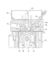
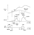
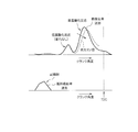
- FIG. 1 is a schematic configuration diagram of an engine to which the present invention is applied and a control system thereof. It is sectional drawing which shows the combustion chamber of a diesel engine, and its peripheral part. It is a block diagram which shows the structure of control systems, such as ECU. It is a schematic diagram of the intake / exhaust system and the combustion chamber for explaining the outline of the combustion mode in the combustion chamber. Change in heat generation rate (heat generation amount per unit rotation angle of crankshaft), change in fuel injection rate (fuel injection amount per unit rotation angle of crankshaft), and in-cylinder gas temperature during the compression / expansion stroke It is a wave form diagram which shows each change of. It is a wave form diagram which shows the change of the heat release rate when a fuel composition changes.
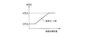
- FIG. 6 also shows a waveform diagram of the fuel injection rate. It is a PV diagram of a diesel engine to which the present invention is applied. It is a figure which shows the setting map of the advance angle guard value of sub injection. It is a graph which shows the relationship between the ignition temperature of the air-fuel
- FIG. 1 is a schematic configuration diagram of the engine 1 and its control system.
- FIG. 2 is a cross-sectional view showing the combustion chamber 3 of the diesel engine and its periphery.
- the engine 1 of this example is configured as a diesel engine system having a fuel supply system 2, a combustion chamber 3, an intake system 6, an exhaust system 7 and the like as main parts.
- the fuel supply system 2 includes a supply pump 21, a common rail 22, an injector (fuel injection valve) 23, a shutoff valve 24, a fuel addition valve 26, an engine fuel passage 27, an addition fuel passage 28, and the like.
- the supply pump 21 pumps fuel from the fuel tank, makes the pumped fuel high pressure, and supplies it to the common rail 22 via the engine fuel passage 27.
- the common rail 22 has a function as a pressure accumulation chamber that holds (accumulates) the high-pressure fuel supplied from the supply pump 21 at a predetermined pressure, and distributes the accumulated fuel to the injectors 23.
- the injector 23 includes a piezoelectric element (piezo element) therein, and is configured by a piezo injector that is appropriately opened to supply fuel into the combustion chamber 3. Details of the fuel injection control from the injector 23 will be described later.
- the supply pump 21 supplies a part of the fuel pumped up from the fuel tank to the fuel addition valve 26 via the addition fuel passage 28.
- the added fuel passage 28 is provided with the shutoff valve 24 for shutting off the added fuel passage 28 and stopping fuel addition in an emergency.
- the fuel addition valve 26 is configured so that the fuel addition amount to the exhaust system 7 becomes a target addition amount (addition amount that makes the exhaust A / F become the target A / F) by an addition control operation by the ECU 100 described later.
- it is constituted by an electronically controlled on-off valve whose valve opening timing is controlled so that the fuel addition timing becomes a predetermined timing. That is, a desired fuel is injected and supplied from the fuel addition valve 26 to the exhaust system 7 (from the exhaust port 71 to the exhaust manifold 72) at an appropriate timing.
- the intake system 6 includes an intake manifold 63 connected to an intake port 15a formed in the cylinder head 15 (see FIG. 2), and an intake pipe 64 constituting an intake passage is connected to the intake manifold 63.
- an air cleaner 65, an air flow meter 43, and a throttle valve (intake throttle valve) 62 are arranged in this intake passage sequentially from the upstream side.
- the air flow meter 43 outputs an electrical signal corresponding to the amount of air flowing into the intake passage via the air cleaner 65.
- the intake system 6 is provided with a swirl control valve (swirl speed variable mechanism) 66 for making the swirl flow (horizontal swirl flow) in the combustion chamber 3 variable.
- a swirl control valve swirl speed variable mechanism
- the intake port 15a two systems of a normal port and a swirl port are provided for each cylinder. Of these, a normal valve 15a shown in FIG. A swirl control valve 66 is arranged.
- An actuator (not shown) is connected to the swirl control valve 66, and the flow rate of air passing through the normal port 15a can be changed according to the opening of the swirl control valve 66 adjusted by driving the actuator. Yes.
- the larger the opening of the swirl control valve 66 the greater the amount of air taken into the cylinder from the normal port 15a.
- the swirl generated by the swirl port becomes relatively weak, and the inside of the cylinder becomes low swirl (a state where the swirl speed is low).
- the smaller the opening of the swirl control valve 66 the smaller the amount of air drawn into the cylinder from the normal port 15a. For this reason, the swirl generated by the swirl port is relatively strengthened, and the inside of the cylinder becomes a high swirl (a state where the swirl speed is high).
- the exhaust system 7 includes an exhaust manifold 72 connected to an exhaust port 71 formed in the cylinder head 15, and exhaust pipes 73 and 74 constituting an exhaust passage are connected to the exhaust manifold 72. .
- a maniverter (exhaust gas purification device) 77 including a NOx storage catalyst (NSR catalyst: NOx Storage Reduction catalyst) 75 and a DPNR catalyst (Diesel Particle-NOx Reduction catalyst) 76 is disposed in the exhaust passage. Yes.
- NSR catalyst 75 and the DPNR catalyst 76 will be described.
- the NSR catalyst 75 is an NOx storage reduction catalyst.
- alumina Al 2 O 3
- potassium (K) sodium (Na), lithium (Li), cesium (Cs) is supported on the carrier, for example.
- Alkali metals such as barium (Ba) and calcium (Ca)
- rare earths such as lanthanum (La) and yttrium (Y)
- noble metals such as platinum (Pt) are supported. It becomes the composition.
- the NSR catalyst 75 occludes NOx in a state where a large amount of oxygen is present in the exhaust gas, has a low oxygen concentration in the exhaust gas, and a large amount of reducing component (for example, an unburned component (HC) of the fuel).
- reducing component for example, an unburned component (HC) of the fuel.
- NOx is reduced to NO 2 or NO and released.
- NO NOx released as NO 2 or NO the N 2 is further reduced due to quickly reacting with HC or CO in the exhaust.
- HC and CO are oxidized to H 2 O and CO 2 by reducing NO 2 and NO. That is, by appropriately adjusting the oxygen concentration and HC component in the exhaust gas introduced into the NSR catalyst 75, HC, CO, and NOx in the exhaust gas can be purified.
- the oxygen concentration and HC component in the exhaust gas can be adjusted by the fuel addition operation from the fuel addition valve 26.
- the DPNR catalyst 76 is, for example, a NOx occlusion reduction catalyst supported on a porous ceramic structure, and PM in the exhaust gas is collected when passing through the porous wall. Further, when the air-fuel ratio of the exhaust gas is lean, NOx in the exhaust gas is stored in the NOx storage reduction catalyst, and when the air-fuel ratio becomes rich, the stored NOx is reduced and released. Further, the DPNR catalyst 76 carries a catalyst that oxidizes and burns the collected PM (for example, an oxidation catalyst mainly composed of a noble metal such as platinum).
- a cylinder block 11 constituting a part of the engine body is formed with a cylindrical cylinder bore 12 for each cylinder (four cylinders), and a piston 13 is formed inside each cylinder bore 12. Is accommodated so as to be slidable in the vertical direction.
- the combustion chamber 3 is formed above the top surface 13 a of the piston 13. That is, the combustion chamber 3 is defined by the lower surface of the cylinder head 15 attached to the upper part of the cylinder block 11 via the gasket 14, the inner wall surface of the cylinder bore 12, and the top surface 13 a of the piston 13.
- a cavity (concave portion) 13 b is formed in a substantially central portion of the top surface 13 a of the piston 13, and this cavity 13 b also constitutes a part of the combustion chamber 3.
- the concave dimension is small in the central portion (on the cylinder center line P), and the concave dimension is increased toward the outer peripheral side. That is, as shown in FIG. 2, when the piston 13 is in the vicinity of the compression top dead center, the combustion chamber 3 formed by the cavity 13b is a narrow space with a relatively small volume in the central portion, and on the outer peripheral side. The structure is such that the space is gradually expanded toward the expansion space.
- the piston 13 has a small end portion 18a of a connecting rod 18 connected by a piston pin 13c, and a large end portion of the connecting rod 18 is connected to a crankshaft which is an engine output shaft.
- a glow plug 19 is disposed toward the combustion chamber 3.
- the glow plug 19 functions as a start-up assisting device that is heated red when an electric current is applied immediately before the engine 1 is started and a part of the fuel spray is blown onto the glow plug 19 to promote ignition and combustion.
- the cylinder head 15 is formed with an intake port 15a (normal port and swirl port) for introducing air into the combustion chamber 3 and an exhaust port 71 for discharging exhaust gas from the combustion chamber 3, respectively.
- An intake valve 16 for opening and closing the port 15a and an exhaust valve 17 for opening and closing the exhaust port 71 are provided.
- the intake valve 16 and the exhaust valve 17 are disposed to face each other with the cylinder center line P interposed therebetween. That is, the engine 1 of this example is configured as a cross flow type.
- the cylinder head 15 is provided with the injector 23 that directly injects fuel into the combustion chamber 3.
- the injector 23 is disposed at a substantially upper center of the combustion chamber 3 in a standing posture along the cylinder center line P, and injects fuel introduced from the common rail 22 toward the combustion chamber 3 at a predetermined timing. It has become.
- the engine 1 is provided with a supercharger (turbocharger) 5.
- the turbocharger 5 includes a turbine wheel 52 and a compressor impeller 53 that are connected via a turbine shaft 51.
- the compressor impeller 53 is arranged facing the inside of the intake pipe 64, and the turbine wheel 52 is arranged facing the inside of the exhaust pipe 73. Therefore, the turbocharger 5 performs a so-called supercharging operation in which the compressor impeller 53 is rotated using the exhaust flow (exhaust pressure) received by the turbine wheel 52 to increase the intake pressure.
- the turbocharger 5 in this example is a variable nozzle type turbocharger (VNT), and a variable nozzle vane mechanism 54 is provided on the turbine wheel 52 side, and an opening degree (VN opening degree) of the variable nozzle vane mechanism 54 is adjusted. By doing so, the supercharging pressure of the engine 1 can be adjusted.
- VNT variable nozzle type turbocharger
- VN opening degree opening degree
- the intake pipe 64 of the intake system 6 is provided with an intercooler 61 for forcibly cooling the intake air whose temperature has been raised by supercharging in the turbocharger 5.
- the throttle valve 62 is provided further downstream than the intercooler 61.
- the throttle valve 62 is an electronically controlled on-off valve whose opening degree can be adjusted in a stepless manner. The throttle air flow area of the intake air is reduced under a predetermined condition, and the supply amount of the intake air is adjusted (reduced). ) Function.
- the engine 1 is provided with an exhaust gas recirculation passage (EGR passage) 8 that connects the intake system 6 and the exhaust system 7.
- the EGR passage 8 is configured to reduce the combustion temperature by recirculating a part of the exhaust gas to the intake system 6 and supplying it again to the combustion chamber 3, thereby reducing the amount of NOx generated.
- the EGR passage 8 is opened and closed steplessly by electronic control, and the exhaust gas passing through the EGR passage 8 (recirculating) is cooled by an EGR valve 81 that can freely adjust the exhaust flow rate flowing through the passage.
- An EGR cooler 82 is provided.
- the EGR passage 8, the EGR valve 81, the EGR cooler 82, and the like constitute an EGR device (exhaust gas recirculation device).
- the air flow meter 43 outputs a detection signal corresponding to the flow rate (intake air amount) of the intake air upstream of the throttle valve 62 in the intake system 6.
- the intake air temperature sensor 49 is disposed in the intake manifold 63 and outputs a detection signal corresponding to the temperature of the intake air.
- the intake pressure sensor 48 is disposed in the intake manifold 63 and outputs a detection signal corresponding to the intake air pressure.
- the A / F (air-fuel ratio) sensor 44 outputs a detection signal that continuously changes in accordance with the oxygen concentration in the exhaust gas downstream of the manipulator 77 of the exhaust system 7.
- the exhaust temperature sensor 45 outputs a detection signal corresponding to the temperature of the exhaust gas (exhaust temperature) downstream of the manipulator 77 of the exhaust system 7.
- the rail pressure sensor 41 outputs a detection signal corresponding to the fuel pressure stored in the common rail 22 (hereinafter also referred to as fuel pressure).
- the throttle opening sensor 42 detects the opening of the throttle valve 62.
- the ECU (Electronic Control Unit) 100 includes a CPU (Central Processing Unit) 101, a ROM (Read Only Memory) 102, a RAM (Random Access Memory) 103, a backup RAM 104, and the like.
- the ROM 102 stores various control programs, maps that are referred to when the various control programs are executed, and the like.
- the CPU 101 executes various arithmetic processes based on various control programs and maps stored in the ROM 102.
- the RAM 103 is a memory that temporarily stores calculation results in the CPU 101, data input from each sensor, and the like.
- the backup RAM 104 is a non-volatile memory that stores data to be saved when the engine 1 is stopped, for example.
- the CPU 101, the ROM 102, the RAM 103, and the backup RAM 104 are connected to each other via the bus 107 and to the input interface 105 and the output interface 106.
- the input interface 105 is connected to the rail pressure sensor 41, the throttle opening sensor 42, the air flow meter 43, the A / F sensor 44, the exhaust temperature sensor 45, the intake pressure sensor 48, and the intake temperature sensor 49. Further, the input interface 105 includes a water temperature sensor 46 that outputs a detection signal corresponding to the cooling water temperature of the engine 1, an accelerator opening sensor 47 that outputs a detection signal corresponding to the depression amount of the accelerator pedal, and the engine 1. A crank position sensor 40 that outputs a detection signal (pulse) each time the output shaft (crankshaft) rotates by a certain angle is connected.
- the supply interface 21, the injector 23, the fuel addition valve 26, the throttle valve 62, the variable nozzle vane mechanism 54, the EGR valve 81, and the like are connected to the output interface 106.
- the ECU 100 executes various controls of the engine 1 based on the outputs of the various sensors described above.
- the ECU 100 executes fuel injection control of the injector 23.
- fuel injection control of the injector 23 sub-injection (pilot injection) and main injection (main injection) are executed.
- combustion by sub-injection is premixed combustion main combustion (also referred to as premixed combustion), and main injection combustion is diffusion combustion main combustion (also referred to as diffusion combustion).
- premixed combustion main combustion also referred to as premixed combustion
- diffusion combustion main combustion also referred to as diffusion combustion.
- the main injection is an injection operation (torque generation fuel supply operation) for generating torque of the engine 1.
- the injection amount in the main injection is basically determined so as to obtain the required torque according to the operating state such as the engine speed, the accelerator operation amount, the coolant temperature, the intake air temperature, and the like. For example, the higher the engine speed (the engine speed calculated based on the output signal of the crank position sensor 40), the greater the accelerator operation amount (the amount of depression of the accelerator pedal detected by the accelerator opening sensor 47). As the accelerator opening becomes larger, the required torque value of the engine 1 is obtained higher, and accordingly, the fuel injection amount in the main injection is set larger.
- the sub-injection is an operation for injecting fuel prior to the main injection from the injector 23. Details of this sub-injection will be described later.
- the main injection is performed in a state in which the preheating in the combustion chamber 3 (inside the cylinder) is sufficiently performed by the premixed combustion in the sub injection, so that the combustion is performed in the main injection.
- the fuel injected into the chamber 3 is immediately exposed to a temperature environment equal to or higher than the self-ignition temperature, and pyrolysis proceeds. After the injection, combustion starts immediately.
- fuel ignition delays in diesel engines include physical delays and chemical delays.
- the physical delay is the time required for evaporation / mixing of the fuel droplets and depends on the gas temperature of the combustion field.
- the chemical delay is the time required for chemical bonding / decomposition of fuel vapor and oxidation heat generation.
- the physical delay can be minimized, and as a result, the ignition delay can be minimized. . Therefore, as a combustion mode of the fuel injected by the main injection, premixed combustion is hardly performed, and most of it is diffusion combustion.
- the injection timing and fuel injection amount of the main injection By adjusting the injection timing and fuel injection amount of the main injection, the ignition timing in diffusion combustion, the rate of change of the heat generation rate [J / CA] (the gradient of the heat generation rate waveform), and the peak of the heat generation rate It becomes possible to control the time when the combustion center of gravity is reached.
- the amount of NOx generated can be suppressed by retarding the injection timing of the main injection for diffusion combustion with respect to TDC and retarding diffusion combustion (retarding the combustion center of gravity of diffusion combustion).
- After injection is an injection operation for increasing the exhaust gas temperature. Specifically, after injection is performed at a timing at which most of the combustion energy of the supplied fuel is obtained as thermal energy of the exhaust gas without being converted into torque of the engine 1.
- the post-injection is an injection operation for directly introducing fuel into the exhaust system 7 to increase the temperature of the manipulator 77. For example, when the accumulated amount of PM trapped in the DPNR catalyst 76 exceeds a predetermined amount (for example, detected by detecting a differential pressure before and after the manipulator 77), post injection is performed. .
- the fuel injection pressure when executing the fuel injection is determined by the internal pressure of the common rail 22.
- the target value of the fuel pressure supplied from the common rail 22 to the injector 23, that is, the target rail pressure increases as the engine load (engine load) increases and as the engine speed (engine speed) increases. It is supposed to be expensive. That is, when the engine load is high, the amount of air sucked into the combustion chamber 3 is large. Therefore, a large amount of fuel must be injected from the injector 23 into the combustion chamber 3, and therefore the injection from the injector 23 is performed.
- the pressure needs to be high.
- the target rail pressure is generally set based on the engine load and the engine speed.
- the target rail pressure is set according to a fuel pressure setting map stored in the ROM 102, for example. That is, by determining the fuel pressure according to this fuel pressure setting map, the valve opening period (injection rate waveform) of the injector 23 is controlled, and the fuel injection amount during the valve opening period can be defined.
- the fuel pressure is adjusted between 30 MPa and 200 MPa according to the engine load and the like. That is, as a control range of the fuel pressure, the lower limit value is 30 MPa and the upper limit value is 200 MPa.
- the optimum value of the fuel injection amount varies depending on the temperature conditions of the engine 1 and the intake air.
- the ECU 100 sets the fuel discharge amount of the supply pump 21 so that the common rail pressure becomes equal to the target rail pressure set based on the engine operating state, that is, the fuel injection pressure matches the target injection pressure. Weigh out. Further, the ECU 100 determines the fuel injection amount and the fuel injection mode based on the engine operating state.
- the ECU 100 calculates the engine rotation speed based on the output signal of the crank position sensor 40, and obtains the depression amount (accelerator opening) of the accelerator pedal based on the output signal of the accelerator opening sensor 47, Based on the engine speed and the accelerator opening, the total fuel injection amount (the sum of the injection amount in the secondary injection and the injection amount in the main injection) is determined.
- the ECU 100 controls the opening degree of the EGR valve 81 according to the operating state of the engine 1 and adjusts the exhaust gas recirculation amount (EGR amount) toward the intake manifold 63.
- the EGR amount is set according to an EGR map stored in advance in the ROM 102.
- this EGR map is a map for determining the EGR amount (EGR rate) using the engine speed and the engine load as parameters. Note that this EGR map is created in advance by experiments, simulations, or the like. That is, by applying the engine speed calculated based on the output signal of the crank position sensor 40 and the opening of the throttle valve 62 (corresponding to the engine load) detected by the throttle opening sensor 42 to the EGR map. An EGR amount (opening degree of the EGR valve 81) is obtained.
- the fuel injection control device for an internal combustion engine of the present invention is realized by the program executed by the ECU 100 described above.
- FIG. 4 gas (air) is sucked into one cylinder of the engine 1 through the intake manifold 63 and the intake port 15 a, and combustion is performed by fuel injection from the injector 23 into the combustion chamber 3.
- FIG. 6 is a diagram schematically showing how the subsequent gas is discharged to the exhaust manifold 72 through the exhaust port 71.
- the gas sucked into the cylinder includes fresh air sucked from the intake pipe 64 through the throttle valve 62 and from the EGR passage 8 when the EGR valve 81 is opened.
- Inhaled EGR gas is included.
- the ratio of the amount of EGR gas (that is, the EGR rate) to the sum of the amount of fresh air (mass) to be sucked and the amount of EGR gas (mass) to be sucked is appropriately controlled by the ECU 100 according to the operating state. It changes according to the opening degree of 81.
- the fresh air and EGR gas sucked into the cylinder (combustion chamber 3) in this way are lowered as the piston 13 (not shown in FIG. 4) descends via the intake valve 16 which is opened in the intake stroke. Then, it is sucked into the cylinder and becomes in-cylinder gas.
- This in-cylinder gas is sealed in the cylinder (inside the combustion chamber 3) by closing the intake valve 16 when the valve is closed according to the operating state of the engine 1 (in-cylinder gas confinement state).
- the piston 13 is compressed as it rises.
- the injector 23 is opened for a predetermined time by the injection amount control by the ECU 100 described above, so that the fuel is directly injected into the combustion chamber 3. Specifically, the sub-injection is executed before the piston 13 reaches the top dead center, and after the fuel injection is temporarily stopped, the piston 13 reaches the vicinity of the top dead center after a predetermined interval (or The main injection is executed after compression top dead center).
- the low-temperature oxidation reaction mainly consists of a fuel having a straight single bond composition such as a normal back end, and the order of low-temperature autoignition is [straight chain]> [side chain]> [cyclic], [single crystal]> [Double bond]> [triple bond].
- the normal paraffinic hydrocarbon contained in the light oil fuel is the main component of the low temperature oxidation reactivity, and the longer the straight chain length, the greater the low temperature oxidation reaction.
- the high-temperature oxidation reaction depends on the reaction in which the straight chain hydrocarbon of the polymer becomes a radical having an unpaired electron, the radical accumulated in the reaction that generates hydrogen peroxide, and the density of peroxidation (H 2 O 2 ). The starting temperature and amount of reaction are determined.
- the high-temperature oxidation reaction is decisive for the amount of radicals and hydrogen peroxide that promote H desorption in the vicinity of hydrocarbon molecules, so the high-temperature oxidation reaction has a predetermined fuel density (spatial density). Is required. Therefore, it is necessary to generate a spray distribution with a density sufficient for radicals, hydrogen peroxide and oxygen by the high temperature oxidation start temperature, and it is necessary to secure a fuel injection amount (premixed combustion amount) that satisfies this. There is.
- the sub-injection is set to early mass single injection.
- BTDC early injection compression ratio 15: BTDC 40 to 25 ° CA
- BTDC 25 ° CA wide-area fuel injection into a wider space is achieved, and the combustion field is reduced in temperature and pressure.
- the premixed combustion by the sub-injection becomes a slow combustion that follows a moderate temperature rise. As a result, it is possible to realize combustion while suppressing the generation amount of NOx and the generation amount of smoke. Furthermore, since the premix combustion before the compression top dead center is slowed down, loss (negative work amount) during the compression stroke can be reduced.
- the premix combustion period can be extended and the premix combustion amount can be maximized.
- the premix combustion period can be extended and the premix combustion amount can be maximized.
- the low-temperature oxidation reaction is hardly affected by the change in the fuel composition because it starts combustion at a temperature-controlled rate (see FIG. 6). Therefore, since the ignition field for the high temperature oxidation reaction can be stably created by the low temperature oxidation reaction, there is an advantage that it is difficult to be affected by changes in the fuel composition.
- the sub-injection is performed as a large-scale single injection at an early stage (for example, BTDC 40 ° CA), and the premixed combustion by the subinjection and the diffusion combustion by the main injection are separated, and further, the premixed combustion is performed.
- the center of gravity of the premixed combustion (the center of gravity of the high temperature oxidation reaction region) can be made around BTDC 10 ° CA.
- the volume change per crank angle of 1 ° CA is small and can be regarded as almost constant.
- the in-cylinder gas pressure can be increased by the combustion, so that the isobaric combustion region is extended to the high pressure side as shown in FIG. Can do.
- isobaric combustion is generated, and the pressure of the isobaric combustion is increased, so that the area on the PV line (area surrounded by the thermal cycle), that is, the work amount, is the case of normal control ( Compared with the broken line in FIG.
- multi-stage divided injection for example, three-stage divided injection
- overdispersed spray in the space increases, causing a problem that unburned HC rapidly increases.
- the injection period of the multistage divided injection is long. , Diffusion combustion is likely to occur.
- the injection timing of the second stage injection (2nd injection) or the third stage injection (3rd injection) is later than 900K
- the fuel injected by the 2nd injection or 3rd injection burns at once. Therefore, diffusion combustion may occur, and the diffusion combustion may retreat to the region after compression top dead center (ATDC). From such a point, it is necessary to adopt the above-described early mass single injection for the sub-injection.
- the required amount of the low-temperature oxidation reaction component is, for example, 1.5 to 2 mm 3 . Further, since the content of the low temperature oxidation reaction component in the light oil fuel is about 15%, the fuel injection amount (sub injection amount) required for the low temperature oxidation reaction is 10 to 13 mm 3 .
- the fuel injection amount can ensure such a low-temperature oxidation reaction amount
- the high-temperature oxidation reaction component when the high-temperature oxidation reaction component is small (when the fuel injection amount of the sub-injection is small), the in-cylinder gas temperature reaches 900K.
- the fuel is overdispersed, and the premixed combustion amount (premixed combustion amount for satisfying the required ignition temperature (for example, 1000 K) of diffusion combustion) before TDC cannot be secured. That is, as described above, the high-temperature oxidation reaction is decisive for the amount of radicals and hydrogen peroxide that promote H desorption in the vicinity of the hydrocarbon molecules.
- the fuel injection amount (necessary for securing the necessary amount of the low-temperature oxidation reaction component and the premixed combustion amount) using the operating state (engine speed and required torque) of the engine 1 as parameters.
- the lower limit amount is obtained by experiments and simulations.
- the amount of the low temperature oxidation reaction component contained in the fuel is also increased, so that the period of the low temperature oxidation reaction becomes longer. If the low-temperature oxidation reaction period becomes long and the low-temperature oxidation reaction cannot be completed before reaching the high-temperature oxidation reaction start temperature (900K), the high-temperature oxidation reaction is combined. In such a situation (low temperature oxidation reaction and high temperature oxidation reaction are combined), combustion becomes sharp and combustion noise becomes a problem. Also, if the fuel injection amount of the secondary injection is increased, the high-temperature oxidation reaction component increases and the density (spray density) increases, so the high-temperature oxidation reaction rate becomes rapid and combustion rapidly evolves. Sound is a problem. From such a point, it is necessary to define the upper limit amount of the fuel injection amount of the sub-injection.
- the operating state (engine speed and required torque) of the engine 1 is used as a parameter, and the upper limit amount of the fuel injection amount is obtained by experiment / simulation in consideration of the combustion noise.
- the fuel injection pattern (injection timing / fuel injection amount of sub-injection for premixed combustion and injection timing / fuel injection amount of main injection for diffusion combustion) is adjusted to execute fuel injection from the injector 23
- a specific control procedure in this case will be described with reference to FIG.
- the fuel injection control ([S1] to [S6] and the like) described below is repeatedly executed by the ECU 100 for each predetermined crank angle (each cylinder). Specifically, for example, when one cylinder is described, every time a combustion stroke of the cylinder is executed, fuel injection control is executed prior to the combustion stroke.
- (Reference crank angle Ainj) For a target engine 1 (for example, a diesel engine having a compression ratio of 15), a bench test or a simulation is performed, and a compressed gas obtained by adding (offset) the motoring temperature waveform shown in FIG. Collect the estimated temperature waveform. From the collected compressed gas temperature estimation waveform, a crank angle [° CA] at which the in-cylinder gas temperature (compressed gas temperature) becomes 750K is obtained. The crank angle of 750K collected in this way is set as a base point (reference crank angle Ainj) for controlling the sub-injection at a temperature-controlled rate. The reference crank angle Ainj is acquired and mapped for each operating state (for example, for each grid point of the operating state map using the engine speed and the required torque as parameters) in the above processing, and stored in the ROM 102 of the ECU 100.
- the reference crank angle Ainj is acquired and mapped for each operating state (for example, for each grid point of the operating state map using the engine speed and the required torque as parameters)
- a retard value of the injection timing (injection start timing) of the main injection with respect to the TDC is determined with reference to the map based on the required NOx amount [g / h] required for the engine 1.
- This retard value map is a map for setting the retard value of the injection timing of the main injection with respect to the TDC using the required NOx amount as a parameter, and is created in advance by experiments, simulations, etc. For example, the ROM 102 of the ECU 100 Is remembered. In this retard value map, the retard value of the injection timing (injection start timing) of the main injection is set to be larger as the required NOx amount is smaller. However, if the delay angle of the diffusion combustion by the main injection for diffusion combustion is too large, misfire occurs, and therefore the upper limit of the delay side of the main injection is limited in order to suppress this.
- the retard angle of the main injection may be limited by setting the injection timing such that the combustion center of gravity of the diffusion combustion by the main injection becomes, for example, ATDC 20 ° CA.
- the retard angle of the main injection may be limited by setting the injection timing such that the combustion center of gravity of the fuel by the main injection becomes, for example, ATDC 15 ° CA, as the retard guard value.
- the fuel injection amount of the main injection is a fuel amount that emphasizes emission reduction, and is smaller than the fuel amount in the case of fuel injection that emphasizes performance (emphasis on engine torque, etc.). .
- the required torque is a satisfactory fuel injection amount.
- the injection period (injection start time to injection end time) of the main injection is calculated based on the fuel injection amount of the main injection and the injection characteristics (injection amount per unit time, etc.) of the injector 23. Then, the injection end timing of the main injection shown in FIG. 5 is determined based on the fuel period of the main injection and the injection timing (injection start timing) of the main injection.
- the upper limit fuel amount map used in the processing of [S3] uses the retard value of the injection timing of the main injection with respect to TDC as a parameter, and the upper limit value of the fuel amount that does not cause smoke in diffusion combustion (can be combusted by retarded diffusion combustion). (Fuel amount) is obtained in advance by experiments, simulations, etc., and a value (upper limit fuel amount) adapted based on the result is mapped, and stored in the ROM 102 of the ECU 100, for example. In this upper limit fuel amount map, the upper limit fuel amount in the diffusion combustion is set to be smaller as the retardation value of the injection timing of the main injection is larger.
- the fuel injection amount of the sub-injection calculated in the process of [S4] ([total fuel injection amount] ⁇ [fuel injection amount of main injection]) is to secure and predict the necessary amount of the low-temperature oxidation reaction component described above.
- the fuel amount sufficiently satisfies the fuel injection amount (lower limit amount) necessary for securing the mixed combustion amount (securing 1000K or more at the time of main injection), and is the fuel amount capable of realizing the above-mentioned early mass single injection.
- crank angle Ainj crank angle that becomes 750K
- the reference crank angle Ainj (crank angle that becomes 750K) is obtained with reference to a map based on the current operation state (for example, engine speed and required torque).
- the injection end timing of the sub-injection shown in FIG. 5 is determined.
- the spray of the sub-injection fuel injection amount (a fuel amount that can secure the low-temperature oxidation reaction required amount) obtained in the process of [S4] reaches the reference crank angle Ainj (750K).
- the injection period (injection start time to injection end time) of the sub-injection is calculated based on the fuel injection amount of the sub-injection and the injection characteristics (injection amount per unit time, etc.) of the injector 23.
- the injection start timing (calculated value) of the sub-injection is retarded or advanced than the following advance guard value, and the injection start timing of the sub-injection is the advance guard value If it is more retarded, the fuel injection pattern as shown in FIG. 5 is determined using the injection start timing and injection end timing of the sub-injection calculated in the above process as they are.
- the sub-injection injection timing is set to the advance guard value in order to further slow down the premixed combustion by the sub-injection. You may make it advance to.
- the injection start timing (calculated value) of the secondary injection is on the advance side of the advance guard value
- the injection timing of the secondary injection is limited to the advance guard value.
- the generated torque is secured by injecting the sub-injection with the after-injection after the main injection. To do.
- the advance angle guard value is obtained with reference to the map of FIG. 8 based on the total fuel injection amount of the secondary injection.
- the map in FIG. 8 is a map of values obtained by empirically adapting the advance angle guard value in advance through experiments, simulations, etc., taking the total fuel injection amount of sub-injection as a parameter and considering the amount of unburned HC generated. For example, it is stored in the ROM 102 of the ECU 100.
- Fuel injection from the injector 23 is executed based on the fuel injection pattern determined as described above (subject injection start timing / injection end timing and main injection start timing / injection end timing). .
- the combustion of the heat release rate waveform as shown in FIG. 5, that is, the combustion center of gravity of premixed combustion and the combustion center of gravity of diffusion combustion are separated, and the premixed combustion is performed at a low temperature oxidation reaction. Combustion separated into a high-temperature oxidation reaction can be realized.
- the premixed combustion and the diffusion combustion are separated, and the premixed combustion is further subjected to low-temperature oxidation. Since fuel injection is controlled so as to be separated into a reaction and a high-temperature oxidation reaction, premixed combustion can be made slow. As a result, the premix combustion period until diffusion combustion can be lengthened, and the preheat amount and the premix combustion amount can be sufficiently secured. As a result, the ignition timing of diffusion combustion by main injection is stabilized, and combustion with high robustness can be realized.
- the sub-injection is set to early injection (for example, BTDC 40 ° CA)
- early injection for example, BTDC 40 ° CA
- wide-area fuel injection into a wide space is possible, and a combustion field with a high oxygen concentration can be generated.
- the premixed combustion becomes a slow combustion by separating into a low temperature oxidation reaction and a high temperature oxidation reaction, it is possible to suppress the generation amount of NOx, the generation amount of smoke and the combustion noise in the premix combustion. it can.
- the amount of fuel for diffusion combustion (main injection fuel injection amount) is reduced in consideration of the NOx amount and smoke, and the premixed combustion amount (sub-injection fuel injection amount) is reduced by the reduced amount. Since it is increasing, it is possible to improve the combustion efficiency while reducing emissions and combustion noise.
- FIG. 5 shows an example in which the injection start timing of the main injection is retarded with respect to TDC.
- the present invention is not limited to this, and the injection start timing of the main injection is around TDC. There may be.
- the fuel injection amount of the main injection (for diffusion combustion) is obtained in consideration of the NOx amount, and the fuel injection amount of the sub-injection is determined from the fuel injection amount of the main injection and the total fuel injection amount.
- the present invention is not limited to this.
- the operating state (engine speed and required torque) of the engine 1 is used as a parameter, and the required fuel injection amount of the sub-injection (the preheating amount and the sub-injection amount is within the range from the lower limit amount to the upper limit amount of the fuel injection amount of the sub injection described above.
- a map for calculating the premixed combustion amount) is prepared in advance by experiments, simulations, etc., and the fuel injection amount of the sub-injection is determined with reference to the map based on the actual operating state of the engine 1. May be.
- the premixed combustion amount can be continuously changed according to the engine operating state, so that an appropriate combustion mode according to the engine operating state can be realized.
- the sub-injection is the above-described BTDC early mass single injection, separation of pre-mixed combustion by sub-injection and diffusion combustion by main injection, and pre-mixed combustion by separating low-temperature oxidation reaction and high-temperature oxidation reaction Can be realized.
- the combustion by the sub-injection is controlled at a temperature rate based on the reference crank angle Ainj (crank angle at which the in-cylinder gas temperature becomes 750K) acquired in advance by a bench test, a simulation, or the like.
- Ainj crank angle at which the in-cylinder gas temperature becomes 750K
- the present invention is not limited to this, and other methods may be adopted.
- the in-cylinder gas temperature may be detected or estimated, a reference crank angle Ainj at which the in-cylinder gas temperature reaches 750K is obtained, and combustion by sub-injection may be controlled at a temperature-controlled rate.
- the intake air temperature obtained from the output signal of the intake air temperature sensor 49 when the intake valve 16 is closed may be used.
- the in-cylinder gas temperature may be estimated using a map or a calculation formula for estimating.
- the present invention is applied to a common rail in-cylinder direct injection multi-cylinder (4-cylinder) diesel engine.
- the present invention is not limited to this, and can be applied to a diesel engine having any number of cylinders such as a six-cylinder diesel engine.
- the engine to which the present invention is applicable is not limited to an automobile engine.
- the manipulator 77 is provided with the NSR catalyst 75 and the DPNR catalyst 76, but may be provided with the NSR catalyst 75 and a DPF (Diesel Particle Filter).
- DPF Diesel Particle Filter
- the present invention can be used in a fuel injection control device for an internal combustion engine represented by a diesel engine, and more specifically, a main injection that performs combustion mainly including diffusion combustion, and an injection that is performed prior to the main injection.
- a fuel injection control device for a compression auto-ignition internal combustion engine that can perform sub-injection that performs combustion mainly of premixed combustion.
Landscapes
- Engineering & Computer Science (AREA)
- Chemical & Material Sciences (AREA)
- Combustion & Propulsion (AREA)
- Mechanical Engineering (AREA)
- General Engineering & Computer Science (AREA)
- Electrical Control Of Air Or Fuel Supplied To Internal-Combustion Engine (AREA)
- Combined Controls Of Internal Combustion Engines (AREA)
Abstract
燃料噴射弁から気筒内に噴射された燃料が気筒内で燃焼する圧縮自着火式の内燃機関であって、燃料噴射弁からの燃料噴射動作として、筒内で拡散燃焼を主体とする燃焼を行わせる主噴射と、この主噴射に先立って行われる噴射であって前記筒内で予混合燃焼を主体とする燃焼を行わせる副噴射とが実行可能な内燃機関において、副噴射による予混合燃焼を低温酸化反応と高温酸化反応とに分離する。このような制御により、予混合燃焼期間を長くすることができ、予混合燃焼量を十分に確保することができる。これによって、エミッションの低減及び燃焼の安定性を確保することが可能な制御を実現することができる。
Description
本発明は、ディーゼルエンジンに代表される圧縮自着火式の内燃機関の燃料噴射制御装置に関する。
自動車用エンジン等として使用されるディーゼルエンジンでは、エンジン回転数、アクセル操作量、冷却水温度、吸気温度等に応じて、燃料噴射弁(以下、インジェクタともいう)からの燃料噴射タイミングや燃料噴射量を調整することにより燃焼室内(気筒内)での燃焼形態を制御することが行われている。
上記ディーゼルエンジンの燃焼は、下記の特許文献1にも開示されているように、主として予混合燃焼と拡散燃焼とにより成り立っている。インジェクタから燃焼室内への燃料噴射が開始されると、まず、燃料の気化拡散により可燃混合気が生成される(着火遅れ期間)。次に、この可燃混合気が燃焼室の数ヶ所でほぼ同時に自己着火し、急速に燃焼が進む(予混合燃焼)。さらに、燃焼室内への燃料噴射が継続され、燃焼が継続的に行われる(拡散燃焼)。その後、燃料噴射が終了した後にも未燃燃料が存在するため、しばらくの間、熱発生が続けられる(後燃え期間)。
また、ディーゼルエンジンにおいては、主噴射(メイン噴射)に先立って副噴射(パイロット噴射)を実行する燃料噴射制御が知られている(例えば、下記の特許文献2を参照)。このような形態の燃料噴射において、先の副噴射での燃焼を予混合燃焼とし、主噴射での燃焼を拡散燃焼とするとともに、その予混合燃焼を制御することによりエミッションの改善を図ることができる。
副噴射によって予混合燃焼を行う燃焼制御において、圧縮上死点(TDC)付近での予混合燃焼量を確保するには、低温低圧場を作成し、さらに自己噴霧冷却干渉または相互噴霧冷却干渉により着火遅れを大きくした燃焼が有効である。しかしながら、このような方法では、筒内の酸素濃度、筒内圧力あるいは燃料組成が設定よりも低下した場合、拡散燃焼の着火遅れが発生して燃焼状態が悪化する場合がある。
本発明はそのような実情を考慮してなされたもので、主噴射と、この主噴射に先立つ副噴射との実行が可能な圧縮自着火式の内燃機関の燃料噴射制御装置において、エミッションの低減及び燃焼の安定性を確保することが可能な制御を実現することを目的とする。
-課題の解決原理-
上記の目的を達成するために講じられた本発明の解決原理は、副噴射の噴射開始時期を圧縮上死点前の早期に設定し、副噴射による予混合燃焼と主噴射による拡散燃焼とを分離した分離燃焼とするとともに、その予混合燃焼を低温酸化反応と高温酸化反応とに分離することで、圧縮上死点前の予混合燃焼期間を拡大し、予混合燃焼量を十分に確保できるようにようにしている。
上記の目的を達成するために講じられた本発明の解決原理は、副噴射の噴射開始時期を圧縮上死点前の早期に設定し、副噴射による予混合燃焼と主噴射による拡散燃焼とを分離した分離燃焼とするとともに、その予混合燃焼を低温酸化反応と高温酸化反応とに分離することで、圧縮上死点前の予混合燃焼期間を拡大し、予混合燃焼量を十分に確保できるようにようにしている。
-解決手段-
本発明は、燃料噴射弁から気筒内に噴射された燃料が気筒内で燃焼する圧縮自着火式の内燃機関の制御に適用され、前記燃料噴射弁から筒内への燃料噴射動作として、少なくとも、前記筒内で拡散燃焼を主体とする燃焼を行わせる主噴射と、この主噴射に先立って行われる噴射であって前記筒内で予混合燃焼を主体とする燃焼を行わせる副噴射とが実行可能な内燃機関の燃料噴射制御装置を前提としており、このような燃料噴射制御装置において、低温酸化反応必要量を確保し、かつ、圧縮上死点前の予混合燃焼量(BTDC予混合燃焼量)を前記主噴射時1000K以上確保可能とするために必要な燃料量を下限として、前記副噴射の燃料噴射量を設定するとともに、前記副噴射で噴射された燃料が、筒内ガス温度が低温酸化反応開始温度になる時点で着火(酸化反応開始)するように、当該副噴射の噴射時期を設定する燃料噴射制御手段を備えていることを特徴としている。本発明において、副噴射の燃料噴射は単発噴射(早期大量単発噴射)で実施する。
本発明は、燃料噴射弁から気筒内に噴射された燃料が気筒内で燃焼する圧縮自着火式の内燃機関の制御に適用され、前記燃料噴射弁から筒内への燃料噴射動作として、少なくとも、前記筒内で拡散燃焼を主体とする燃焼を行わせる主噴射と、この主噴射に先立って行われる噴射であって前記筒内で予混合燃焼を主体とする燃焼を行わせる副噴射とが実行可能な内燃機関の燃料噴射制御装置を前提としており、このような燃料噴射制御装置において、低温酸化反応必要量を確保し、かつ、圧縮上死点前の予混合燃焼量(BTDC予混合燃焼量)を前記主噴射時1000K以上確保可能とするために必要な燃料量を下限として、前記副噴射の燃料噴射量を設定するとともに、前記副噴射で噴射された燃料が、筒内ガス温度が低温酸化反応開始温度になる時点で着火(酸化反応開始)するように、当該副噴射の噴射時期を設定する燃料噴射制御手段を備えていることを特徴としている。本発明において、副噴射の燃料噴射は単発噴射(早期大量単発噴射)で実施する。
本発明によれば、副噴射で噴射された燃料が、筒内ガス温度が低温酸化反応開始温度になる時点で着火するように当該副噴射の噴射時期を設定しているので、圧縮上死点前(BTDC)の予混合燃焼を、低温酸化反応と高温酸化反応とに分離することができる。この点について以下に説明する。
まず、ディーゼルエンジンの燃料である軽油には、低温酸化反応成分(ノルマルセタン等の直鎖単結合組成の燃料)が含まれている。この低温酸化反応成分は750Kで酸化反応(燃焼)を開始する。また、低温酸化反応成分以外の成分の大部分は900Kで酸化反応(高温酸化反応)を開始する。
本発明は、そのような点つまり低温酸化反応開始温度と高温酸化反応開始温度との温度差に着目し、副噴射で噴射された燃料が、筒内ガス温度が低温酸化反応開始温度(750K)になる時点で着火(酸化反応開始)するように、当該副噴射の噴射時期を設定している。このような燃料噴射制御を行うことにより、例えば、図5に示すように、圧縮行程において圧縮ガス温度(筒内ガス温度)が750Kに到達した時点で、噴霧燃料のうちの低温酸化反応成分の燃焼(低温酸化反応)が開始され、その後に、筒内ガス温度が900K(高温酸化反応開始温度)に到達した時点で残りの成分の燃焼(高温酸化反応)が開始されるようになる。これによって、副噴射による予混合燃焼を低温酸化反応と高温酸化反応とに分離することができる。
そして、このようにして、予混合燃焼を低温酸化反応と高温酸化反応とに分離することにより、低温酸化反応から高温酸化反応へのつなぎが悪化しても、主噴射による拡散燃焼の着火時期の燃焼勾配は維持することができる。つまり、本発明におけるBTDC予混合燃焼は、下記のように早期着火(早期噴射)を実現した燃焼であるため、高温酸化反応速度の低下や着火遅れが発生しても、TDCまでに余裕があり、その余裕分で高温酸化反応速度の低下や着火遅れを吸収することができる。また、着火遅れが発生しても、筒内ガス温度は上昇継続(図5参照)であり燃焼場の着火性が改善される。これらのことにより、拡散燃焼の着火時期が安定し、ロバスト性の高い燃焼を実現することができる。また、燃焼音を抑制することができる。
しかも、圧縮過程において圧縮ガス温度が750Kに到達した時点で低温酸化反応を開始させる燃料噴射(副噴射)は、圧縮上死点前の早期噴射(例えば、BTDC40~25°CA)となるため、それよりもTDCに近い側(例えば、BTDC25°CA以降)の燃料噴射と比べて、広い空間への広域燃料噴射になるとともに、燃焼場の低温化及び低圧化が可能になるので、副噴射による予混合燃焼が緩やかな温度上昇に追従する緩慢な燃焼となる。これによって、NOxの発生量、スモークの発生量、燃焼音を抑制した燃焼を実現することができる。さらに、圧縮上死点前の予混合燃焼が緩慢化することにより、圧縮行程中のロス(負の仕事量)を低減することができる。
また、燃料組成の変化(例えば、低セタン価の燃料使用)があっても、低温酸化反応は温度律速で燃焼を開始するため燃料組成変化の影響は殆ど受けない(図6参照)。したがって、低温酸化反応によって、高温酸化反応の着火場を常に安定して作成することができるので、燃料組成変化の影響を受け難いという利点もある。
次に、予混合燃焼用の副噴射の燃料噴射量及び噴射時期などについて説明する。
<副噴射の燃料噴射量>
まず、低温酸化反応成分の必要量は、例えば1.5~2mm3である。また、軽油燃料中の低温酸化反応成分の含有率は15%程度であるので、低温酸化反応に必要な燃料噴射量(副噴射量)は10~13mm3となる。
まず、低温酸化反応成分の必要量は、例えば1.5~2mm3である。また、軽油燃料中の低温酸化反応成分の含有率は15%程度であるので、低温酸化反応に必要な燃料噴射量(副噴射量)は10~13mm3となる。
また、そのような低温酸化反応必要量を確保できる燃料噴射量であっても、高温酸化反応成分が少ないと(副噴射の燃料噴射量が少ないと)、筒内ガス温度が900Kに到達したときに燃料が過分散の状態となってしまい、TDCまでに必要な予混合燃焼量(拡散燃焼の要求着火温度(例えば1000K)を満足するための予混合燃焼量)を確保できなくなる。すなわち、高温酸化反応は、炭化水素分子の周辺にH脱離を促進するラジカルや過酸化水素がどれだけ存在するかが決め手となるため、高温酸化反応は所定の燃料密度(空間密度)が必要になるが、燃料噴射量が少ないと、900Kまでにラジカルと過酸化水素及び酸素が充足する密度となる噴霧分布を生成することができなくなってしまい、BTDC予混合燃焼量を確保できなくなる。したがって、このような点を考慮して副噴射の燃料噴射量の下限量を規定する必要がある。また、本発明では、TDCまでに必要な予混合燃焼量を確保するために、上記下限量以上の大量の燃料を早期に単発で噴射する。
上記副噴射の燃料噴射量の下限量については、例えば、内燃機関の運転状態(機関回転数及び機関トルク)をパラメータとして、上記低温酸化反応成分の必要量及び予混合燃焼量を確保するのに必要な燃料噴射量(下限量)を、実験・シミュレーション等によって求めておけばよい。
一方、副噴射の燃料噴射量を増加すると、上記予混合燃焼量が増加して主燃料噴射による拡散燃焼の着火性が良くなるが、副噴射の燃料噴射量を増加しすぎると、以下の点が問題となる。
副噴射の燃料噴射量を増加すると、燃料中に含まれる低温酸化反応成分の量も増加するため低温酸化反応の期間が長くなる。その低温酸化反応期間が長くなって高温酸化反応開始温度(900K)に到達するまでに低温酸化反応が終了できなくなると、高温酸化反応と合体してしまう。こうした状況(低温酸化反応と高温酸化反応とが合体した状況)になると、燃焼が急峻となるため燃焼音が問題となる。また、副噴射の燃料噴射量を増加すると、高温酸化反応成分が増加して密度(噴霧密度)が急増するため、高温酸化反応速度が急速となってしまい、この場合も燃焼音が問題となる。このような点から副噴射の燃料噴射量の上限量を規定する必要がある。
その副噴射の燃料噴射量の下限量については、例えば、内燃機関の運転状態(機関回転数及び機関トルク)をパラメータとして、上記燃焼音を考慮して燃料噴射量の上限量を、実験・シミュレーション等によって求めておけばよい。
そして、副噴射の燃料噴射量を、上記した下限量以上の燃料量(上限は上記上限量で制限)に設定して、上記した早期大量単発噴射を行うことによって、低温酸化反応と高温酸化反応とを分離することができ、上述した、燃焼が緩慢で燃焼音が低減された予混合燃焼を実現することができる。
<副噴射の噴射時期>
副噴射の噴射時期は、その副噴射で噴射された燃料が、筒内ガス温度が750K(低温酸化反応開始温度)になる時点で着火(酸化反応開始)するような時期であればよいが、より好ましくは、筒内ガス温度が750Kに到達するまでに、低温酸化反応必要量を確保可能な燃料量の全ての噴霧が気化する時期がよい。
副噴射の噴射時期は、その副噴射で噴射された燃料が、筒内ガス温度が750K(低温酸化反応開始温度)になる時点で着火(酸化反応開始)するような時期であればよいが、より好ましくは、筒内ガス温度が750Kに到達するまでに、低温酸化反応必要量を確保可能な燃料量の全ての噴霧が気化する時期がよい。
また、上述したように、圧縮ガス温度が750Kに到達した時点で低温酸化反応を開始させるための燃料噴射(副噴射)はBTDC早期噴射であり、その噴射時期を進角するほど、より広い空間への広域噴射となるが、副噴射の噴射時期を進角し過ぎると、未燃HC(Hydrocarbons:炭化水素)が増加してしまう。これを抑止するために副噴射の進角量を進角ガード値にて制限する必要がある。その進角ガード値は、未燃HCの発生量を考慮して、実験・シミュレーション等によって決定すればよい。
<主噴射による拡散燃焼>
本発明において、エミッション低減を重視して、NOxやスモークの発生量を抑制する場合、主噴射による拡散燃焼を遅角するとともに、主噴射の燃料噴射量を少なくすればよい。具体的には、例えば、内燃機関に対して要求される要求NOx量に応じて、拡散燃焼用の主噴射の噴射時期をTDCに対して遅角して拡散燃焼を遅角することで、NOx量を要求通りの値に規制する。このようにNOx発生量を抑制するには、拡散燃焼用の主噴射の噴射時期を遅角して拡散燃焼用噴射の燃料噴射量を少なくする必要がある。
本発明において、エミッション低減を重視して、NOxやスモークの発生量を抑制する場合、主噴射による拡散燃焼を遅角するとともに、主噴射の燃料噴射量を少なくすればよい。具体的には、例えば、内燃機関に対して要求される要求NOx量に応じて、拡散燃焼用の主噴射の噴射時期をTDCに対して遅角して拡散燃焼を遅角することで、NOx量を要求通りの値に規制する。このようにNOx発生量を抑制するには、拡散燃焼用の主噴射の噴射時期を遅角して拡散燃焼用噴射の燃料噴射量を少なくする必要がある。
こうした点を考慮して、本発明では、主噴射のTDCに対する遅角(拡散燃焼の遅角)によるトルクの低下抑止と酸素濃度低減によるスモークの発生を抑止するために、要求NOx量に応じて主噴射の噴射時期を遅角して拡散燃焼を遅角するにあたり、その遅角拡散燃焼で燃焼可能な燃料量(遅角拡散燃焼でスモークが発生しない上限燃料量)を主噴射の燃料噴射量とする。このようにして主噴射の燃料噴射量の上限を制限することで、拡散燃焼用の燃料が余剰に噴射されることがなくなるので、拡散燃焼でのスモークの発生を抑止することができる。
そして、その遅角を行う主噴射の燃料噴射量と総燃料噴射量とに基づいて、予混合燃焼用の副噴射の燃料噴射量を決定する(例えば、上記遅角により主噴射の燃料噴射量を減らした分だけ副噴射の燃料噴射量を増加する)。このとき、上述したように、副噴射の燃料噴射量が多くなり過ぎると燃焼音が大きくなるので、この点を考慮して副噴射の燃料噴射量の上記した上限量で制限する。この場合、副噴射の燃料噴射量が上限量よりも多くなる場合、その余剰燃料量分については、拡散燃焼用の主噴射の後において噴射(アフタ噴射)することで発生トルクを確保する。
本発明によれば、拡散燃焼を主体とする燃焼を行わせる主噴射と、この主噴射に先立って行われる噴射であって予混合燃焼を主体とする燃焼を行わせる副噴射との実行が可能な圧縮自着火式の内燃機関の燃料噴射制御装置において、副噴射による予混合燃焼を低温酸化反応と高温酸化反応とに分離しているので、予混合燃焼期間を長くすることができ、予混合燃焼量を十分に確保することができる。これによって、エミッションの低減及び燃焼の安定性を確保することが可能な制御を実現することができる。
以下、本発明の実施形態を図面に基づいて説明する。
本実施形態は、自動車に搭載されたコモンレール式筒内直噴型多気筒(例えば直列4気筒)ディーゼルエンジン(圧縮自着火式内燃機関)に本発明を適用した場合について説明する。
-エンジンの構成-
まず、本発明を適用するディーゼルエンジン(以下、単にエンジンという)の一例について説明する。図1はエンジン1及びその制御系統の概略構成図である。また図2は、ディーゼルエンジンの燃焼室3及びその周辺部を示す断面図である。
まず、本発明を適用するディーゼルエンジン(以下、単にエンジンという)の一例について説明する。図1はエンジン1及びその制御系統の概略構成図である。また図2は、ディーゼルエンジンの燃焼室3及びその周辺部を示す断面図である。
図1に示すように、この例のエンジン1は、燃料供給系2、燃焼室3、吸気系6、排気系7等を主要部とするディーゼルエンジンシステムとして構成されている。
燃料供給系2は、サプライポンプ21、コモンレール22、インジェクタ(燃料噴射弁)23、遮断弁24、燃料添加弁26、機関燃料通路27、添加燃料通路28等を備えて構成されている。
上記サプライポンプ21は、燃料タンクから燃料を汲み上げ、この汲み上げた燃料を高圧にした後、機関燃料通路27を介してコモンレール22に供給する。コモンレール22は、サプライポンプ21から供給された高圧燃料を所定圧力に保持(蓄圧)する蓄圧室としての機能を有し、この蓄圧した燃料を各インジェクタ23に分配する。インジェクタ23は、その内部に圧電素子(ピエゾ素子)を備え、適宜開弁して燃焼室3内に燃料を噴射供給するピエゾインジェクタにより構成されている。このインジェクタ23からの燃料噴射制御の詳細については後述する。
また、上記サプライポンプ21は、燃料タンクから汲み上げた燃料の一部を、添加燃料通路28を介して燃料添加弁26に供給する。添加燃料通路28には、緊急時において添加燃料通路28を遮断して燃料添加を停止するための上記遮断弁24が備えられている。
また、上記燃料添加弁26は、後述するECU100による添加制御動作によって排気系7への燃料添加量が目標添加量(排気A/Fが目標A/Fとなるような添加量)となるように、また、燃料添加タイミングが所定タイミングとなるように開弁時期が制御される電子制御式の開閉弁により構成されている。つまり、この燃料添加弁26から所望の燃料が適宜のタイミングで排気系7(排気ポート71から排気マニホールド72)に噴射供給される構成となっている。
吸気系6は、シリンダヘッド15(図2参照)に形成された吸気ポート15aに接続される吸気マニホールド63を備え、この吸気マニホールド63に、吸気通路を構成する吸気管64が接続されている。また、この吸気通路には、上流側から順に、エアクリーナ65、エアフローメータ43、スロットルバルブ(吸気絞り弁)62が配設されている。エアフローメータ43は、エアクリーナ65を介して吸気通路に流入される空気量に応じた電気信号を出力するようになっている。
また、この吸気系6には、図2に示すように、燃焼室3内でのスワール流(水平方向の旋回流)を可変とするためのスワールコントロールバルブ(スワール速度可変機構)66が備えられている。具体的に、上記吸気ポート15aとしては、ノーマルポート及びスワールポートの2系統が各気筒毎に備えられており、そのうち図2に示されているノーマルポート15aに、開度調整可能なバタフライバルブからなるスワールコントロールバルブ66が配置されている。このスワールコントロールバルブ66には図示しないアクチュエータが連繋されており、このアクチュエータの駆動によって調整されるスワールコントロールバルブ66の開度に応じてノーマルポート15aを通過する空気の流量が変更できるようになっている。そして、スワールコントロールバルブ66の開度が大きいほど、ノーマルポート15aから気筒内に吸入される空気量が増加する。このため、スワールポート(図2では図示省略)により発生したスワールは相対的に弱まり、気筒内は低スワール(スワール速度が低い状態)となる。逆に、スワールコントロールバルブ66の開度が小さいほど、ノーマルポート15aから気筒内に吸入される空気量が減少する。このため、スワールポートにより発生したスワールは相対的に強められ、気筒内は高スワール(スワール速度が高い状態)となる。
排気系7は、シリンダヘッド15に形成された排気ポート71に接続される排気マニホールド72を備えており、この排気マニホールド72に対して、排気通路を構成する排気管73,74が接続されている。また、この排気通路には、NOx吸蔵触媒(NSR触媒:NOx Storage Reduction触媒)75、及び、DPNR触媒(Diesel Paticulate-NOx Reduction触媒)76を備えたマニバータ(排気浄化装置)77が配設されている。以下、これらNSR触媒75及びDPNR触媒76について説明する。
NSR触媒75は、吸蔵還元型NOx触媒であって、例えば、アルミナ(Al2O3)を担体とし、この担体上に例えばカリウム(K)、ナトリウム(Na)、リチウム(Li)、セシウム(Cs)のようなアルカリ金属、バリウム(Ba)、カルシウム(Ca)のようなアルカリ土類、ランタン(La)、イットリウム(Y)のような希土類と、白金(Pt)のような貴金属とが担持された構成となっている。
このNSR触媒75は、排気中に多量の酸素が存在している状態においてはNOxを吸蔵し、排気中の酸素濃度が低く、かつ還元成分(例えば燃料の未燃成分(HC))が多量に存在している状態においてはNOxをNO2もしくはNOに還元して放出する。NO2やNOとして放出されたNOxは、排気中のHCやCOと速やかに反応することによってさらに還元されてN2となる。また、HCやCOは、NO2やNOを還元することで、自身は酸化されてH2OやCO2となる。すなわち、NSR触媒75に導入される排気中の酸素濃度やHC成分を適宜調整することにより、排気中のHC、CO、NOxを浄化することができるようになっている。本実施形態のものでは、この排気中の酸素濃度やHC成分の調整を、燃料添加弁26からの燃料添加動作によって行うことが可能となっている。
一方、DPNR触媒76は、例えば、多孔質セラミック構造体にNOx吸蔵還元型触媒を担持させたものであり、排気ガス中のPMは多孔質の壁を通過する際に捕集される。また、排気ガスの空燃比がリーンの場合、排気ガス中のNOxはNOx吸蔵還元型触媒に吸蔵され、空燃比がリッチになると、吸蔵したNOxは還元・放出される。さらに、DPNR触媒76には、捕集したPMを酸化・燃焼する触媒(例えば白金等の貴金属を主成分とする酸化触媒)が担持されている。
ここで、ディーゼルエンジンの燃焼室3及びその周辺部の構成について、図2を用いて説明する。この図2に示すように、エンジン本体の一部を構成するシリンダブロック11には、各気筒(4気筒)毎に円筒状のシリンダボア12が形成されており、各シリンダボア12の内部にはピストン13が上下方向に摺動可能に収容されている。
ピストン13の頂面13aの上側には上記燃焼室3が形成されている。つまり、この燃焼室3は、シリンダブロック11の上部にガスケット14を介して取り付けられたシリンダヘッド15の下面と、シリンダボア12の内壁面と、ピストン13の頂面13aとにより区画形成されている。そして、ピストン13の頂面13aの略中央部には、キャビティ(凹陥部)13bが凹設されており、このキャビティ13bも燃焼室3の一部を構成している。
なお、このキャビティ13bの形状としては、その中央部分(シリンダ中心線P上)では凹陥寸法が小さく、外周側に向かうに従って凹陥寸法が大きくなっている。つまり、図2に示すように、ピストン13が圧縮上死点付近にある際、このキャビティ13bによって形成される燃焼室3としては、中央部分では比較的容積の小さい狭小空間とされ、外周側に向かって次第に空間が拡大される(拡大空間とされる)構成となっている。
上記ピストン13は、コネクティングロッド18の小端部18aがピストンピン13cにより連結されており、このコネクティングロッド18の大端部はエンジン出力軸であるクランクシャフトに連結されている。これにより、シリンダボア12内でのピストン13の往復移動がコネクティングロッド18を介してクランクシャフトに伝達され、このクランクシャフトが回転することでエンジン出力が得られるようになっている。また、燃焼室3に向けてグロープラグ19が配設されている。このグロープラグ19は、エンジン1の始動直前に電流が流されることにより赤熱し、これに燃料噴霧の一部が吹きつけられることで着火・燃焼が促進される始動補助装置として機能する。
上記シリンダヘッド15には、燃焼室3へ空気を導入する吸気ポート15a(ノーマルポート及びスワールポート)と、燃焼室3から排気ガスを排出する上記排気ポート71とがそれぞれ形成されているとともに、吸気ポート15aを開閉する吸気バルブ16及び排気ポート71を開閉する排気バルブ17が配設されている。これら吸気バルブ16及び排気バルブ17はシリンダ中心線Pを挟んで対向配置されている。つまり、この例のエンジン1はクロスフロータイプとして構成されている。また、シリンダヘッド15には、燃焼室3の内部へ直接的に燃料を噴射する上記インジェクタ23が取り付けられている。このインジェクタ23は、シリンダ中心線Pに沿う起立姿勢で燃焼室3の略中央上部に配設されており、上記コモンレール22から導入される燃料を燃焼室3に向けて所定のタイミングで噴射するようになっている。
さらに、図1に示すように、このエンジン1には、過給機(ターボチャージャ)5が設けられている。このターボチャージャ5は、タービンシャフト51を介して連結されたタービンホイール52及びコンプレッサインペラ53を備えている。コンプレッサインペラ53は吸気管64の内部に臨んで配置され、タービンホイール52は排気管73の内部に臨んで配置されている。このためターボチャージャ5は、タービンホイール52が受ける排気流(排気圧)を利用してコンプレッサインペラ53を回転させ、吸気圧を高めるといった所謂過給動作を行うようになっている。この例のターボチャージャ5は、可変ノズル式ターボチャージャ(VNT)であって、タービンホイール52側に可変ノズルベーン機構54が設けられており、この可変ノズルベーン機構54の開度(VN開度)を調整することによってエンジン1の過給圧を調整することができる。
吸気系6の吸気管64には、ターボチャージャ5での過給によって昇温した吸入空気を強制冷却するためのインタークーラ61が設けられている。このインタークーラ61よりも更に下流側に上記スロットルバルブ62が設けられている。スロットルバルブ62は、その開度を無段階に調整することができる電子制御式の開閉弁であり、所定の条件下において吸入空気の流路面積を絞り、この吸入空気の供給量を調整(低減)する機能を有している。
また、エンジン1には、吸気系6と排気系7とを接続する排気還流通路(EGR通路)8が設けられている。このEGR通路8は、排気の一部を適宜吸気系6に還流させて燃焼室3へ再度供給することにより燃焼温度を低下させ、これによってNOx発生量を低減させるものである。また、このEGR通路8には、電子制御によって無段階に開閉され、同通路を流れる排気流量を自在に調整することができるEGRバルブ81と、EGR通路8を通過(還流)する排気を冷却するためのEGRクーラ82とが設けられている。これらEGR通路8、EGRバルブ81、EGRクーラ82等によってEGR装置(排気還流装置)が構成されている。
-センサ類-
エンジン1の各部位には、各種センサが取り付けられており、それぞれの部位の環境条件や、エンジン1の運転状態に関する信号を出力する。
エンジン1の各部位には、各種センサが取り付けられており、それぞれの部位の環境条件や、エンジン1の運転状態に関する信号を出力する。
例えば、上記エアフローメータ43は、吸気系6内のスロットルバルブ62の上流において吸入空気の流量(吸入空気量)に応じた検出信号を出力する。吸気温センサ49は、吸気マニホールド63に配置され、吸入空気の温度に応じた検出信号を出力する。吸気圧センサ48は、吸気マニホールド63に配置され、吸入空気圧力に応じた検出信号を出力する。A/F(空燃比)センサ44は、排気系7のマニバータ77の下流において排気中の酸素濃度に応じて連続的に変化する検出信号を出力する。排気温センサ45は、同じく排気系7のマニバータ77の下流において排気ガスの温度(排気温度)に応じた検出信号を出力する。レール圧センサ41はコモンレール22内に蓄えられている燃料の圧力(以下、燃圧ともいう)に応じた検出信号を出力する。スロットル開度センサ42はスロットルバルブ62の開度を検出する。
-ECU-
ECU(Electronic Control Unit)100は、図3に示すように、CPU(Central Processing Unit)101、ROM(Read Only Memory)102、RAM(Random Access Memory)103及びバックアップRAM104などを備えている。ROM102は、各種制御プログラムや、それら各種制御プログラムを実行する際に参照されるマップ等が記憶されている。CPU101は、ROM102に記憶された各種制御プログラムやマップに基づいて各種の演算処理を実行する。RAM103は、CPU101での演算結果や各センサから入力されたデータ等を一時的に記憶するメモリである。バックアップRAM104は、例えばエンジン1の停止時にその保存すべきデータ等を記憶する不揮発性のメモリである。
ECU(Electronic Control Unit)100は、図3に示すように、CPU(Central Processing Unit)101、ROM(Read Only Memory)102、RAM(Random Access Memory)103及びバックアップRAM104などを備えている。ROM102は、各種制御プログラムや、それら各種制御プログラムを実行する際に参照されるマップ等が記憶されている。CPU101は、ROM102に記憶された各種制御プログラムやマップに基づいて各種の演算処理を実行する。RAM103は、CPU101での演算結果や各センサから入力されたデータ等を一時的に記憶するメモリである。バックアップRAM104は、例えばエンジン1の停止時にその保存すべきデータ等を記憶する不揮発性のメモリである。
以上のCPU101、ROM102、RAM103及びバックアップRAM104は、バス107を介して互いに接続されるとともに、入力インターフェース105及び出力インターフェース106と接続されている。
入力インターフェース105には、上記レール圧センサ41、スロットル開度センサ42、エアフローメータ43、A/Fセンサ44、排気温センサ45、吸気圧センサ48、吸気温センサ49が接続されている。さらに、この入力インターフェース105には、エンジン1の冷却水温に応じた検出信号を出力する水温センサ46、アクセルペダルの踏み込み量に応じた検出信号を出力するアクセル開度センサ47、及び、エンジン1の出力軸(クランクシャフト)が一定角度回転する毎に検出信号(パルス)を出力するクランクポジションセンサ40などが接続されている。
一方、出力インターフェース106には、上記サプライポンプ21、インジェクタ23、燃料添加弁26、スロットルバルブ62、可変ノズルベーン機構54、及び、EGRバルブ81などが接続されている。
そして、ECU100は、上記した各種センサの出力に基づいて、エンジン1の各種制御を実行する。
また、ECU100は、インジェクタ23の燃料噴射制御を実行する。このインジェクタ23の燃料噴射制御として、副噴射(パイロット噴射)と主噴射(メイン噴射)とを実行する。
この実施形態では、副噴射による燃焼を予混合燃焼主体の燃焼(予混合燃焼ともいう)とし、主噴射による燃焼を拡散燃焼主体の燃焼(拡散燃焼ともいう)とするとともに、後述するように、副噴射を、ピストン13の圧縮上死点前(BTDC)の早期噴射(早期大量単発噴射)とすることにより、それら予混合燃焼の重心と拡散燃焼の重心(例えば、熱発生率が最大となるクランク角度)とを分離している点(図5参照)に特徴がある。そして、このようにして、予混合燃焼をと拡散燃焼とを分離することにより、それぞれの燃焼の優位点を利用することができるので、排気エミッションの改善及び燃焼の安定性を図ることができる。
上記主噴射は、エンジン1のトルク発生のための噴射動作(トルク発生用燃料の供給動作)である。この主噴射での噴射量は、基本的には、エンジン回転数、アクセル操作量、冷却水温度、吸気温度等の運転状態に応じ、要求トルクが得られるように決定される。例えば、エンジン回転数(クランクポジションセンサ40の出力信号に基づいて算出されるエンジン回転数)が高いほど、また、アクセル操作量(アクセル開度センサ47により検出されるアクセルペダルの踏み込み量)が大きいほど(アクセル開度が大きいほど)エンジン1のトルク要求値としては高く得られ、それに応じて主噴射での燃料噴射量としても多く設定されることになる。
上記副噴射は、インジェクタ23からの主噴射に先立ち、燃料を噴射する動作である。この副噴射の詳細については後述する。
ここで、この実施形態では、上記副噴射での予混合燃焼によって燃焼室3内(気筒内)の予熱が十分に行われた状態で上記主噴射が実行されることにより、この主噴射で燃焼室3内に噴射された燃料は、直ちに自着火温度以上の温度環境下に晒されて熱分解が進み、噴射後は直ちに燃焼が開始されることになる。
具体的に、ディーゼルエンジンにおける燃料の着火遅れとしては、物理的遅れと化学的遅れとがある。物理的遅れは、燃料液滴の蒸発・混合に要する時間であり、燃焼場のガス温度に左右される。一方、化学的遅れは、燃料蒸気の化学的結合・分解かつ酸化発熱に要する時間である。そして、上記副噴射による予混合燃焼により燃焼室内の予熱が十分になされている状況では上記物理的遅れを最小限に抑えることができ、その結果として、着火遅れも最小限に抑えられることになる。したがって、主噴射によって噴射された燃料の燃焼形態としては、予混合燃焼が殆ど行われないことになり、大部分が拡散燃焼となる。そして、この主噴射の噴射時期や燃料噴射量を調整することで、拡散燃焼での着火時期、熱発生率[J/CA]の変化割合(熱発生率波形の勾配)、熱発生率のピーク、燃焼重心に達する時期を共に制御することが可能になる。
また、拡散燃焼用の主噴射の噴射時期をTDCに対して遅角して、拡散燃焼を遅角(拡散燃焼の燃焼重心を遅角)することにより、NOx発生量を抑制することができる。
なお、以上の副噴射及び主噴射の他に、アフタ噴射やポスト噴射が必要に応じて行われる。アフタ噴射は、排気ガス温度を上昇させるための噴射動作である。具体的には、供給された燃料の燃焼エネルギがエンジン1のトルクに変換されることなく、その大部分が排気の熱エネルギとして得られるタイミングでアフタ噴射は実行される。また、ポスト噴射は、排気系7に燃料を直接的に導入して上記マニバータ77の昇温を図るための噴射動作である。例えば、DPNR触媒76に捕集されているPMの堆積量が所定量を超えた場合(例えばマニバータ77の前後の差圧を検出することにより検知)、ポスト噴射が実行されるようになっている。
-燃料噴射圧-
燃料噴射を実行する際の燃料噴射圧は、コモンレール22の内圧により決定される。このコモンレール内圧として、一般に、コモンレール22からインジェクタ23へ供給される燃料圧力の目標値つまり目標レール圧は、エンジン負荷(機関負荷)が高くなるほど、及び、エンジン回転数(機関回転数)が高くなるほど高いものとされる。すなわち、エンジン負荷が高い場合には燃焼室3内に吸入される空気量が多いため、インジェクタ23から燃焼室3内に向けて多量の燃料を噴射しなければならず、よってインジェクタ23からの噴射圧力を高いものとする必要がある。また、エンジン回転数が高い場合には噴射可能な期間が短いため、単位時間当たりに噴射される燃料量を多くしなければならず、よってインジェクタ23からの噴射圧力を高いものとする必要がある。このように、目標レール圧は一般にエンジン負荷及びエンジン回転数に基づいて設定される。なお、この目標レール圧は、例えば上記ROM102に記憶された燃圧設定マップに従って設定される。つまり、この燃圧設定マップに従って燃料圧力を決定することで、インジェクタ23の開弁期間(噴射率波形)が制御され、その開弁期間中における燃料噴射量を規定することが可能になる。
燃料噴射を実行する際の燃料噴射圧は、コモンレール22の内圧により決定される。このコモンレール内圧として、一般に、コモンレール22からインジェクタ23へ供給される燃料圧力の目標値つまり目標レール圧は、エンジン負荷(機関負荷)が高くなるほど、及び、エンジン回転数(機関回転数)が高くなるほど高いものとされる。すなわち、エンジン負荷が高い場合には燃焼室3内に吸入される空気量が多いため、インジェクタ23から燃焼室3内に向けて多量の燃料を噴射しなければならず、よってインジェクタ23からの噴射圧力を高いものとする必要がある。また、エンジン回転数が高い場合には噴射可能な期間が短いため、単位時間当たりに噴射される燃料量を多くしなければならず、よってインジェクタ23からの噴射圧力を高いものとする必要がある。このように、目標レール圧は一般にエンジン負荷及びエンジン回転数に基づいて設定される。なお、この目標レール圧は、例えば上記ROM102に記憶された燃圧設定マップに従って設定される。つまり、この燃圧設定マップに従って燃料圧力を決定することで、インジェクタ23の開弁期間(噴射率波形)が制御され、その開弁期間中における燃料噴射量を規定することが可能になる。
なお、本実施形態では、エンジン負荷等に応じて燃料圧力が30MPa~200MPaの間で調整されるようになっている。つまり、燃料圧力の制御範囲として、下限値が30MPaであり、上限値が200MPaとなっている。
上記燃料噴射量の最適値はエンジン1や吸入空気等の温度条件によって異なるものとなる。例えば、上記ECU100は、コモンレール圧がエンジン運転状態に基づいて設定される目標レール圧と等しくなるように、つまり、燃料噴射圧が目標噴射圧と一致するように、サプライポンプ21の燃料吐出量を調量する。また、ECU100は、エンジン運転状態に基づいて燃料噴射量及び燃料噴射形態を決定する。具体的には、ECU100は、クランクポジションセンサ40の出力信号に基づいてエンジン回転速度を算出するとともに、アクセル開度センサ47の出力信号に基づいてアクセルペダルの踏み込み量(アクセル開度)を求め、このエンジン回転速度及びアクセル開度に基づいて総燃料噴射量(副噴射での噴射量と主噴射での噴射量との和)を決定する。
また、ECU100は、エンジン1の運転状態に応じてEGRバルブ81の開度を制御し、吸気マニホールド63に向けての排気還流量(EGR量)を調整する。このEGR量は、上記ROM102に予め記憶されたEGRマップに従って設定される。具体的に、このEGRマップは、エンジン回転数及びエンジン負荷をパラメータとしてEGR量(EGR率)を決定するためのマップである。なお、このEGRマップは、予め実験やシミュレーション等によって作成されたものとなっている。つまり、上記クランクポジションセンサ40の出力信号に基づいて算出されたエンジン回転数及びスロットル開度センサ42によって検出されたスロットルバルブ62の開度(エンジン負荷に相当)とをEGRマップに当て嵌めることでEGR量(EGRバルブ81の開度)が得られるようになっている。
以上のECU100により実行されるプログラムによって、本発明の内燃機関の燃料噴射制御装置が実現される。
-燃焼形態の概略説明-
次に、本実施形態に係るエンジン1における燃焼室3内での燃焼形態の概略について説明する。
次に、本実施形態に係るエンジン1における燃焼室3内での燃焼形態の概略について説明する。
図4は、エンジン1の1つの気筒に対して吸気マニホールド63及び吸気ポート15aを経てガス(空気)が吸入され、燃焼室3内へインジェクタ23からの燃料噴射によって燃焼が行われるとともに、その燃焼後のガスが排気ポート71を経て排気マニホールド72へ排出される様子を模式的に示した図である。
この図4に示すように、気筒内に吸入されるガスには、吸気管64からスロットルバルブ62を介して吸入された新気と、上記EGRバルブ81が開弁された場合にEGR通路8から吸入されるEGRガスとが含まれる。吸入される新気量(質量)と吸入されるEGRガス量(質量)との和に対するEGRガス量の割合(すなわち、EGR率)は、運転状態に応じて上記ECU100により適宜制御されるEGRバルブ81の開度に応じて変化する。
このようにして気筒内(燃焼室3内)に吸入された新気及びEGRガスは、吸気行程において開弁している吸気バルブ16を介し、ピストン13(図4では図示省略)の下降に伴って気筒内に吸入されて筒内ガスとなる。この筒内ガスは、エンジン1の運転状態に応じて決定されるバルブ閉弁時にて吸気バルブ16が閉弁することにより気筒内(燃焼室3内)に密閉され(筒内ガスの閉じ込め状態)、その後の圧縮行程においてピストン13の上昇に伴って圧縮される。そして、ピストン13が上死点近傍に達すると、上述したECU100による噴射量制御によって所定時間だけインジェクタ23が開弁されることで燃料を燃焼室3内に直接噴射する。具体的には、ピストン13が上死点に達する前に上記副噴射が実行され、燃料噴射が一旦停止された後、所定のインターバルを経て、ピストン13が上死点近傍に達した時点(もしくは圧縮上死点以降)で上記主噴射が実行されることになる。
次に、燃料噴射制御に関する事項について説明する。
-軽油燃料について-
ディーゼルエンジンに使用される軽油燃料は、C=10~15の炭化水素を基本とし、炭素の配置で直鎖・側鎖(分岐)・環状に大別される。この炭素配置において、炭素間の結合状態は単結合、二重結合、三重結合が存在する。
ディーゼルエンジンに使用される軽油燃料は、C=10~15の炭化水素を基本とし、炭素の配置で直鎖・側鎖(分岐)・環状に大別される。この炭素配置において、炭素間の結合状態は単結合、二重結合、三重結合が存在する。
筒内のガス温度による加熱で燃料が気化した後、炭素鎖の一部が酸化還元を繰り返しながら炭素鎖の鎖結合が切り離され、炭素単体の酸化(CO2)の燃焼へと遷移する。その一連の炭素鎖の分解に必要な温度(熱エネルギ)は組成によって変化する。現在流通している物性イメージを図9示す。低温酸化反応は、ノルマル背端等の直鎖単結合組成の燃料が主体であって、その低温自着火の序列は、[直鎖]>[側鎖]>[環状]、[単結晶]>[二重結合]>[三重結合]となる。
-低温酸化反応・高温酸化反応について-
軽油燃料中に含有されたノルマルパラフィン系炭化水素が低温酸化反応性の主体であって、直鎖の長さが長いほど低温酸化反応は大きくなる。高温酸化反応は、高分子の直鎖炭化水素が不対電子を持つラジカルになる反応と、過酸化水素を生成する反応で蓄積されたラジカルと、過酸化(H2O2)の密度とによって反応の開始温度や反応量が確定する。
軽油燃料中に含有されたノルマルパラフィン系炭化水素が低温酸化反応性の主体であって、直鎖の長さが長いほど低温酸化反応は大きくなる。高温酸化反応は、高分子の直鎖炭化水素が不対電子を持つラジカルになる反応と、過酸化水素を生成する反応で蓄積されたラジカルと、過酸化(H2O2)の密度とによって反応の開始温度や反応量が確定する。
低温酸化反応は各分子が自力で反応するため、噴霧の分散度合いに関係なく低温酸化反応は発生する。これに対し、高温酸化反応は、炭化水素分子の周辺にH脱離を促進するラジカルや過酸化水素がどれだけ存在するかが決め手となるため、高温酸化反応は所定の燃料密度(空間密度)が必要になる。したがって、高温酸化開始温度までにラジカルと過酸化水素及び酸素が充足する密度となる噴霧分布を生成しなければならず、これを満足するような燃料噴射量(予混合燃焼量)を確保する必要がある。
そして、低温酸化反応必要量を確保することが可能な燃料量を、筒内ガス温度が750Kに到達するまでに噴霧を気化させることによって、900Kで高温酸化反応が開始するようになり、TDC到着までに余裕を持った燃焼を構築することが可能になる。このような燃焼を実現するために、本発明では、副噴射を早期大量単発噴射とする。具体的には、BTDC早期噴射(圧縮比15:BTDC40~25°CA)とする。このようなBTDC早期噴射を行うと、それよりもTDCに近い側(BTDC25°CA以降)の燃料噴射と比べて、広い空間への広域燃料噴射になるとともに、燃焼場の低温化及び低圧化が可能になるので、副噴射による予混合燃焼が緩やかな温度上昇に追従する緩慢な燃焼となる。これによって、NOxの発生量、スモークの発生量を抑制した燃焼を実現することができる。さらに、圧縮上死点前の予混合燃焼が緩慢化することにより、圧縮行程中のロス(負の仕事量)を低減することができる。
そして、上述の如く、低温酸化反応必要量を確保することが可能な燃料量を750K到達までに噴霧を気化させ、900Kで高温酸化反応を開始させる燃焼制御を行うことにより、例えば、図5に示すように、圧縮行程において圧縮ガス温度(筒内ガス温度)が750Kに到達した時点で、噴霧燃料のうちの低温酸化反応成分の燃焼(低温酸化反応)が開始され、その後に、筒内ガス温度が900Kに到達した時点で、残りの成分の燃焼(高温酸化反応)が開始されるようになる。これにより副噴射による予混合燃焼を低温酸化反応と高温酸化反応とに分離することができる。
このようにして予混合燃焼を低温酸化反応と高温酸化反応とに分離することにより、予混合燃焼期間を拡大することができ、予混合燃焼量を最大化することができる。これによって、高温酸化反応速度の低下や着火遅れが発生しても、TDCまでに余裕があり、その余裕分で、高温酸化反応速度の低下や着火遅れを吸収することができる。また、着火遅れが発生しても、筒内ガス温度は上昇継続(図5参照)であり燃焼場の着火性が改善されるので、拡散燃焼の着火時期が安定し、ロバスト性の高い燃焼を実現することができる。また、燃焼音を抑制することができる。
さらに、使用する燃料の組成変化(例えば、低セタン価の燃料使用)があっても、低温酸化反応は温度律速で燃焼を開始するため燃料組成変化の影響は殆ど受けない(図6参照)。したがって、低温酸化反応によって高温酸化反応の着火場を安定して作成することができるので、燃料組成変化の影響を受け難いという利点もある。
ここで、本実施形態では、上述の如く、副噴射を早期(例えばBTDC40°CA)の大量単発噴射として、副噴射による予混合燃焼と主噴射による拡散燃焼とを分離し、さらに、予混合燃焼を低温酸化反応と高温酸化反応とに分離しているので、予混合燃焼の重心(高温酸化反応領域の重心)を、BTDC10°CA付近にすることができる。BTDC10°CA付近では、クランク角度1°CAあたりの体積変化が小さくて、ほぼ定容とみなすことができる。したがって、燃焼重心がBTDC10°CA付近の予混合燃焼を生成すると、その燃焼によって筒内ガス圧を高くすることができるので、図7に示すように、等容的燃焼域を高圧側に延ばすことができる。これによって、等圧的燃焼が生成されるようになり、しかも、その等圧的燃焼の圧力が高くなるので、PV線上の面積(熱サイクル囲まれる面積)つまり仕事量を、通常制御の場合(図7の破線)と比較して大きくすることができる。
なお、副噴射については、多段分割噴射(例えば3段分割噴射)とすることが一般に行われており、その多段分割噴射をBTDC早期に実施することも考えられるが、副噴射として多段分割噴射を採用した場合、上記した早期大量単発噴射よりも早期(進角側)に噴射を開始する必要がある。そのため、空間への過分散噴霧が増加してしまい、未燃HCが急増するという問題が発生する。しかも、多段分割噴射の1段目(1st)の噴射時期を早期に設定しても、多段分割噴射の噴射期間(例えば、1段目の噴射~3段目の噴射までの期間)が長いため、拡散燃焼が生じやすくなる。例えば、2段目の噴射(2nd噴射)や3段目の噴射(3rd噴射)の噴射時期が900Kよりも後の時期になると、その2nd噴射や3rd噴射で噴射された燃料は一気に燃えてしまうので拡散燃焼化し、その拡散燃焼が圧縮上死点後(ATDC)の領域まで後退することがある。このような点から、副噴射については、上記した早期大量単発噴射を採用する必要がある。
-副噴射の燃料噴射量-
まず、上述したように、低温酸化反応成分の必要量は例えば1.5~2mm3である。また、軽油燃料中の低温酸化反応成分の含有率は15%程度であるので、低温酸化反応に必要な燃料噴射量(副噴射量)は10~13mm3となる。
まず、上述したように、低温酸化反応成分の必要量は例えば1.5~2mm3である。また、軽油燃料中の低温酸化反応成分の含有率は15%程度であるので、低温酸化反応に必要な燃料噴射量(副噴射量)は10~13mm3となる。
また、そのような低温酸化反応必要量を確保できる燃料噴射量であっても、高温酸化反応成分が少ないと(副噴射の燃料噴射量が少ないと)、筒内ガス温度が900Kに到達したときに燃料が過分散の状態となってしまい、TDCまでに必要な予混合燃焼量(拡散燃焼の要求着火温度(例えば1000K)を満足するための予混合燃焼量)を確保できなくなる。すなわち、高温酸化反応は、上述したように、炭化水素分子の周辺にH脱離を促進するラジカルや過酸化水素がどれだけ存在するかが決め手となるため、高温酸化反応は所定の燃料密度(空間密度)が必要になるが、燃料噴射量が少ないと、高温酸化開始温度(900K)までに、ラジカルと過酸化水素及び酸素が充足する密度となる噴霧分布を生成することができなくなってしまい、BTDC予混合燃焼量を確保できなくなる。したがって、このような点を考慮して副噴射の燃料噴射量の下限量を規定する必要がある。
そこで、本実施形態では、例えば、エンジン1の運転状態(エンジン回転数及び要求トルク)をパラメータとして、上記低温酸化反応成分の必要量及び予混合燃焼量を確保するのに必要な燃料噴射量(下限量)を、実験・シミュレーション等によって求めておく。
一方、上述したように、副噴射の燃料噴射量を増加すると、上記予混合燃焼量が増加して主燃料噴射による拡散燃焼の着火性が良くなるが、副噴射の燃料噴射量を増加しすぎると、以下の点が問題となる。
副噴射の燃料噴射量を増加すると、燃料中に含まれる低温酸化反応成分の量も増加するため低温酸化反応の期間が長くなる。その低温酸化反応期間が長くなって、高温酸化反応開始温度(900K)に到達するまでに低温酸化反応が終了できなくなると、高温酸化反応と合体してしまう。こうした状況(低温酸化反応と高温酸化反応とが合体)になると、燃焼が急峻化してしまい、燃焼音が問題となる。また、副噴射の燃料噴射量を増加すると、高温酸化反応成分が増加して密度(噴霧密度)が増加するため、高温酸化反応速度が急速となって燃焼が急進化してしまい、この場合も燃焼音が問題となる。このような点から副噴射の燃料噴射量の上限量を規定する必要がある。
そこで、本実施形態では、例えば、エンジン1の運転状態(エンジン回転数及び要求トルク)をパラメータとし、上記燃焼音を考慮して燃料噴射量の上限量を実験・シミュレーション等によって求めておく。
-具体的な制御手順-
次に、燃料噴射パターン(予混合燃焼用の副噴射の噴射時期・燃料噴射量、及び、拡散燃焼用の主噴射の噴射時期・燃料噴射量)を調整してインジェクタ23からの燃料噴射を実行する場合の具体的な制御手順について図5を参照して説明する。
次に、燃料噴射パターン(予混合燃焼用の副噴射の噴射時期・燃料噴射量、及び、拡散燃焼用の主噴射の噴射時期・燃料噴射量)を調整してインジェクタ23からの燃料噴射を実行する場合の具体的な制御手順について図5を参照して説明する。
なお、以下に説明する燃料噴射制御([S1]~[S6]等)は、ECU100において所定のクランク角度毎(各気筒毎)に繰り返して実行される。具体的に、例えば、1つの気筒について説明すると、その気筒の燃焼行程が実行される度に、その燃焼行程に先立って燃料噴射制御が実行される。
まず、ECU100が実行する制御の説明の前に、筒内ガス温度が750Kとなる基準クランク角度Ainj[°CA]について説明する。
(基準クランク角度Ainj)
対象とするエンジン1(例えば、圧縮比15のディーゼルエンジン)について、ベンチテストあるいはシミュレーションなどを行って、図5に示すモータリング温度波形と、負荷運転での蓄熱分を加算(オフセット)した圧縮ガス温度推定波形とを採取する。その採取した圧縮ガス温度推定波形から、筒内ガス温度(圧縮ガス温度)が750Kになるクランク角度[°CA]を求める。このようにして採取した750Kとなるクランク角度を、副噴射を温度律速で制御するための基点(基準クランク角度Ainj)とする。この基準クランク角度Ainjについては、上記処理にて運転状態毎(例えば、エンジン回転数と要求トルクとをパラメータとする運転状態マップの格子点毎)に取得してマップ化しておき、ECU100のROM102内に記憶しておく。
対象とするエンジン1(例えば、圧縮比15のディーゼルエンジン)について、ベンチテストあるいはシミュレーションなどを行って、図5に示すモータリング温度波形と、負荷運転での蓄熱分を加算(オフセット)した圧縮ガス温度推定波形とを採取する。その採取した圧縮ガス温度推定波形から、筒内ガス温度(圧縮ガス温度)が750Kになるクランク角度[°CA]を求める。このようにして採取した750Kとなるクランク角度を、副噴射を温度律速で制御するための基点(基準クランク角度Ainj)とする。この基準クランク角度Ainjについては、上記処理にて運転状態毎(例えば、エンジン回転数と要求トルクとをパラメータとする運転状態マップの格子点毎)に取得してマップ化しておき、ECU100のROM102内に記憶しておく。
(燃料噴射制御)
この例では、エンジン1に対して要求されている要求NOx量を満足しながらも、副噴射による予熱量及び予混合燃焼量を最大にする場合について説明する。
この例では、エンジン1に対して要求されている要求NOx量を満足しながらも、副噴射による予熱量及び予混合燃焼量を最大にする場合について説明する。
[S1]エンジン回転数、アクセル操作量、冷却水温、吸入空気温度等の運転状態や環境条件などに基づいて、総燃料噴射量([副噴射の燃料噴射量]+[主噴射の燃料噴射量])を公知のマップ等を参照して求める。
[S2]エンジン1に対して要求されている要求NOx量[g/h]に基づいてマップを参照して、TDCに対する主噴射の噴射時期(噴射開始時期)の遅角値を決定する。
この遅角値マップは、要求NOx量をパラメータとして、TDCに対する主噴射の噴射時期の遅角値を設定するためのマップであって、予め実験・シミュレーション等により作成されており、例えばECU100のROM102に記憶されている。この遅角値マップにおいて、要求NOx量が小さいほど、主噴射の噴射時期(噴射開始時期)の遅角値が大きくなるように設定されている。ただし、拡散燃焼用の主噴射による拡散燃焼の遅角が大き過ぎると失火が発生するので、これを抑止するために主噴射の遅角側の上限は制限されている。
なお、このように失火を抑止する場合、主噴射による拡散燃焼の燃焼重心が例えばATDC20°CAとなるような噴射時期を遅角ガード値として主噴射の遅角を制限すればよい。また、燃焼効率を優先する場合、主噴射による燃料の燃焼重心が、例えばATDC15°CAとなるような噴射時期を遅角ガード値として主噴射の遅角を制限すればよい。
[S3]上記[S2]の処理で決定した主噴射の噴射時期の遅角値に基づいて、その遅角値での燃料噴射による拡散噴射で燃焼可能な燃料量(遅角拡散燃焼でスモークが発生しない上限燃料量)をマップから求め、その上限燃料量を主噴射の燃料噴射量とする。
なお、この主噴射の燃料噴射量は、上述の如く、エミッション低減を重視した燃料量であって、性能重視(エンジントルク重視等)の燃料噴射の場合の燃料量と比較して少ない量となる。ただし、要求トルクは満足できる燃料噴射量である。
次に、上記主噴射の燃料噴射量及びインジェクタ23の噴射特性(単位時間当たりの噴射量等)に基づいて主噴射の噴射期間(噴射開始時期~噴射終了時期)を算出する。そして、その主噴射の燃料期間及び上記主噴射の噴射時期(噴射開始時期)に基づいて、図5に示す主噴射の噴射終了時期を決定する。
この[S3]の処理に用いる上限燃料量マップは、主噴射の噴射時期のTDCに対する遅角値をパラメータとして、拡散燃焼でスモークが発生しない燃料量の上限値(遅角拡散燃焼で燃焼可能な燃料量)を予め実験・シミュレーション等によって取得しておき、その結果を基に適合した値(上限燃料量)をマップ化したものであって、例えばECU100のROM102に記憶されている。この上限燃料量マップにおいて、主噴射の噴射時期の遅角値が大きいほど、拡散燃焼での上限燃料量が小さくなるように設定されている。
[S4]上記[S1]の処理で求めた総燃料噴射量、及び、上記[S3]の処理で決定した主噴射の燃料噴射量を用いて、副噴射の燃料噴射量([副噴射の燃料噴射量]=[総燃料噴射量]-[主噴射の燃料噴射量])を算出する。次に、算出した副噴射の燃料噴射量が、上記した上限量(予混合燃焼の燃焼音を考慮した上限量)よりも多いか否かを判断し、副噴射の燃料噴射量が上限量以下であれば、上記処理で算出したままの値を副噴射の燃料噴射量とする。一方、算出した副噴射の燃料噴射量が上限量よりも多い場合、その上限量をオーバーする量(余剰燃料量)については、主噴射の後のアフタ噴射で噴射することにより発生トルクを確保する。
ここで、この[S4]の処理で算出した副噴射の燃料噴射量([総燃料噴射量]-[主噴射の燃料噴射量])は、上記した低温酸化反応成分の必要量の確保及び予混合燃焼量を確保(主噴射時1000K以上確保)するのに必要な燃料噴射量(下限量)を十分に満足する燃料量であって、上記早期大量単発噴射を実現できる燃料量である。
[S5]上記基準クランク角度Ainj(750Kになるクランク角度)を、現在の運転状態(例えば、エンジン回転数及び要求トルク)に基づいてマップを参照して求める。この基準クランク角度Ainj(750Kになるクランク角度)を用いて、図5に示す副噴射の噴射終了時期を決定する。
具体的には、上記[S4]の処理で取得した副噴射の燃料噴射量(低温酸化反応必要量を確保することが可能な燃料量)の噴霧が、上記基準クランク角度Ainj(750K)に到達するまでに気化するように、副噴射の噴射終了時期をAinjよりも所定量α(例えば、α=5°CA)だけ進角した時期に設定する([副噴射の噴射終了時期]=[Ainj-α])。さらに、上記副噴射の燃料噴射量及びインジェクタ23の噴射特性(単位時間当たりの噴射量等)に基づいて副噴射の噴射期間(噴射開始時期~噴射終了時期)を算出する。そして、その副噴射の噴射期間と上記噴射終了時期とから、図5に示す副噴射の噴射開始時期を決定する([副噴射の噴射開始時期]=[副噴射の噴射終了時期]-[副噴射の噴射期間])。
このとき、副噴射の噴射開始時期(算出値)が下記の進角ガード値よりも遅角側であるか、進角側であるのかを判断し、副噴射の噴射開始時期が進角ガード値よりも遅角側であれば、上記した処理で算出した副噴射の噴射開始時期及び噴射終了時期をそののまま用いて、図5に示すような燃料噴射パターンを決定する。なお、副噴射の噴射時期(算出値)が進角ガード値よりも遅角側である場合、この副噴射による予混合燃焼を更に緩慢化するために、副噴射の噴射時期を進角ガード値まで進角するようにしてもよい。
一方、副噴射の噴射開始時期(算出値)が進角ガード値よりも進角側である場合は、その進角ガード値に副噴射の噴射時期を制限する。このとき、副噴射の燃料噴射量を減量補正する必要がある場合、その副噴射の減量補正分(余剰燃料量分)については、主噴射の後のアフタ噴射で噴射することにより発生トルクを確保する。
ここで、上記進角ガード値は、副噴射の総燃料噴射量に基づいて図8のマップを参照して求める。図8のマップは、副噴射の総燃料噴射量をパラメータとし、未燃HCの発生量を考慮して、予め実験・シミュレーション等によって進角ガード値を経験的に適合した値をマップ化したものであって、例えばECU100のROM102内に記憶されている。
[S6]以上のようにして決定した燃料噴射パターン(副噴射の噴射開始時期・噴射終了時期、及び、主噴射の噴射開始時期・噴射終了時期)に基づいてインジェクタ23からの燃料噴射を実行する。このような燃料噴射制御により、図5に示すような熱発生率波形の燃焼、つまり、予混合燃焼の燃焼重心と拡散燃焼の燃焼重心とが分離されるとともに、予混合燃焼が低温酸化反応と高温酸化反応とに分離された燃焼を実現することができる。
以上説明したように、この実施形態によれば、燃焼室内で予混合燃焼と拡散燃焼とが行われるエンジン1において、予混合燃焼と拡散燃焼とが分離され、さらに、その予混合燃焼が低温酸化反応と高温酸化反応とに分離されるように燃料噴射を制御しているので、予混合燃焼を緩慢な燃焼とすることができる。これによって拡散燃焼までの予混合燃焼期間を長くすることができるとともに、予熱量及び予混合燃焼量を十分に確保することができる。その結果として、主噴射による拡散燃焼の着火時期が安定し、ロバスト性の高い燃焼を実現することができる。
また、副噴射を早期噴射(例えば、BTDC40°CA)としているので、広い空間への広域燃料噴射が可能になるとともに、高酸素濃度の燃焼場を生成することができる。これによってNOxの発生量、スモークの発生量を抑制した燃焼を実現することができる。さらに、低温酸化反応と高温酸化反応とに分離して予混合燃焼が緩慢な燃焼となるようにしているので、予混合燃焼におけるNOxの発生量、スモークの発生量及び燃焼音を抑制することができる。
しかも、この実施形態では、NOx量及びスモークを考慮して拡散燃焼用の燃料量(主噴射の燃料噴射量)を減らし、その減量した分だけ予混合燃焼量(副噴射の燃料噴射量)を増加しているので、エミッション及び燃焼音を低減しながらも燃焼効率の向上を図ることができる。
なお、図5に示す例では、主噴射の噴射開始時期をTDCに対して遅角した場合の例を示しているが、これに限定されることなく、主噴射の噴射開始時期はTDC付近であってもよい。
また、以上説明した実施形態では、NOx量を考慮して主噴射(拡散燃焼用)の燃料噴射量を求め、その主噴射の燃料噴射量と総燃料噴射量とから副噴射の燃料噴射量を求めているが、本発明はこれに限定されない。
例えば、エンジン1の運転状態(エンジン回転数及び要求トルク)をパラメータとし、上記した副噴射の燃料噴射量の下限量から上限量までの範囲内において、副噴射の要求燃料噴射量(予熱量及び予混合燃焼量)を算出するマップを予め実験・シミュレーション等によって作成しておき、実際のエンジン1の運転状態に基づいて上記マップを参照して副噴射の燃料噴射量を決定するというを採用してもよい。
このような燃料噴射制御を採用すると、エンジン運転状態に応じて予混合燃焼量を連続的に変化させることが可能になるので、エンジン運転状態に応じた適正な燃焼形態を実現することができる。なお、この場合も、副噴射を上記したBTDC早期大量単発噴射として、副噴射による予混合燃焼と主噴射による拡散燃焼との分離、及び、低温酸化反応と高温酸化反応とを分離した予混合燃焼を実現できるようにする。
-他の実施形態-
以上の例では、ベンチテストやシミュレーション等によって予め取得した基準クランク角度Ainj(筒内ガス温度が750Kとなるクランク角度)を基点として副噴射による燃焼を温度律速で制御しているが、本発明はこれに限られることなく、他の方法を採用してもよい。
以上の例では、ベンチテストやシミュレーション等によって予め取得した基準クランク角度Ainj(筒内ガス温度が750Kとなるクランク角度)を基点として副噴射による燃焼を温度律速で制御しているが、本発明はこれに限られることなく、他の方法を採用してもよい。
例えば、エンジン運転中において、筒内ガス温度を検出または推定し、その筒内ガス温度が750Kに達する基準クランク角度Ainjを求めて、副噴射による燃焼を温度律速で制御するようにしてもよい。なお、筒内ガス温度については、吸気バルブ16の閉弁時において上記吸気温センサ49の出力信号から得られる吸気温度を用いてもよいし、外気温やエンジン運転状態等にから筒内ガス温度を推定するマップや計算式を用いて筒内ガス温度を推定するようにしてもよい。
以上の例では、コモンレール式筒内直噴型多気筒(4気筒)ディーゼルエンジンに本発明を適用した場合について説明した。本発明はこれに限らず、例えば6気筒ディーゼルエンジンなど他の任意の気筒数のディーゼルエンジンにも適用可能である。また、本発明が適用可能なエンジンは、自動車用のエンジンに限るものではない。
以上の例では、通電期間においてのみ全開の開弁状態となることにより燃料噴射率を変更するピエゾインジェクタ23を適用したエンジン1について説明したが、本発明は、可変噴射率インジェクタを適用したエンジンへの適用も可能である。
以上の例では、マニバータ77として、NSR触媒75及びDPNR触媒76を備えたものとしたが、NSR触媒75及びDPF(Diesel Paticulate Filter)を備えたものとしてもよい。
本発明は、ディーゼルエンジンに代表される内燃機関の燃料噴射制御装置に利用可能であり、さらに詳しくは、拡散燃焼を主体とする燃焼を行わせる主噴射と、この主噴射に先立って行われる噴射であって予混合燃焼を主体とする燃焼を行わせる副噴射との実行が可能な圧縮自着火式の内燃機関の燃料噴射制御装置に有効に利用することができる。
1 エンジン(内燃機関)
2 燃料供給系
3 燃焼室(気筒)
21 サプライポンプ
23 インジェクタ(燃料噴射弁)
40 クランクポジションセンサ
46 水温センサ
47 アクセル開度センサ
49 吸気温センサ
100 ECU
2 燃料供給系
3 燃焼室(気筒)
21 サプライポンプ
23 インジェクタ(燃料噴射弁)
40 クランクポジションセンサ
46 水温センサ
47 アクセル開度センサ
49 吸気温センサ
100 ECU
Claims (8)
- 燃料噴射弁から気筒内に噴射された燃料が気筒内で燃焼する圧縮自着火式の内燃機関の制御に適用され、前記燃料噴射弁から筒内への燃料噴射動作として、少なくとも、前記筒内で拡散燃焼を主体とする燃焼を行わせる主噴射と、この主噴射に先立って行われる噴射であって前記筒内で予混合燃焼を主体とする燃焼を行わせる副噴射とが実行可能な内燃機関の燃料噴射制御装置において、
低温酸化反応必要量を確保し、かつ、圧縮上死点前の予混合燃焼量を前記主噴射時1000K以上確保可能とするために必要な燃料量を下限として、前記副噴射の燃料噴射量を設定するとともに、前記副噴射で噴射された燃料が、筒内ガス温度が低温酸化反応開始温度になる時点で着火するように、当該副噴射の噴射時期を設定する燃料噴射制御手段を備えていることを特徴とする内燃機関の燃料噴射制御装置。 - 請求項1記載の内燃機関の燃料噴射制御装置において、
前記副噴射による燃料噴射を単発噴射で実施することを特徴とする噴射する内燃機関の燃料噴射制御装置。 - 請求項1または2記載の内燃機関の燃料噴射制御装置において、
前記筒内ガス温度が前記低温酸化反応開始温度に到達するまでに、前記低温酸化反応必要量を確保することが可能な燃料量が気化するように、前記副噴射の噴射時期が設定されていることを特徴とする内燃機関の燃料噴射制御装置。 - 請求項1~3のいずれか1つに記載の内燃機関の燃料噴射制御装置において、
前記低温酸化反応が、筒内ガス温度が高温酸化反応開始温度に到達するまでに終了するように、前記副噴射の燃料噴射量が設定されていることを特徴とする内燃機関の燃料噴射制御装置。 - 請求項1~4のいずれか1つに記載の内燃機関の燃料噴射制御装置において、
要求NOx量に応じて、前記主噴射の噴射時期を圧縮上死点に対して遅角して拡散燃焼を遅角することを特徴とする内燃機関の燃料噴射制御装置。 - 請求項5記載の内燃機関の燃料噴射制御装置において、
要求NOx量に応じて拡散燃焼を遅角するにあたり、その遅角拡散燃焼で燃焼可能な燃料量を前記主噴射の燃料噴射量とし、その主噴射噴射の燃料噴射量と要求総燃料噴射量とに基づいて前記副噴射の燃料噴射量を決定することを特徴とする内燃機関の燃料噴射制御装置。 - 請求項1~6のいずれか1つに記載の内燃機関の燃料噴射制御装置において、
前記副噴射の噴射時期は進角ガード値によって制限されていることを特徴とする内燃機関の燃料噴射制御装置。 - 請求項7記載の内燃機関の燃料噴射制御装置において、
前記副噴射の噴射時期の進角ガード値は未燃炭化水素の発生量を考慮して設定されることを特徴とする内燃機関の燃料噴射制御装置。
Priority Applications (2)
| Application Number | Priority Date | Filing Date | Title |
|---|---|---|---|
| JP2011532426A JP5115660B2 (ja) | 2011-03-30 | 2011-03-30 | 内燃機関の燃料噴射制御装置 |
| PCT/JP2011/058087 WO2012131950A1 (ja) | 2011-03-30 | 2011-03-30 | 内燃機関の燃料噴射制御装置 |
Applications Claiming Priority (1)
| Application Number | Priority Date | Filing Date | Title |
|---|---|---|---|
| PCT/JP2011/058087 WO2012131950A1 (ja) | 2011-03-30 | 2011-03-30 | 内燃機関の燃料噴射制御装置 |
Publications (1)
| Publication Number | Publication Date |
|---|---|
| WO2012131950A1 true WO2012131950A1 (ja) | 2012-10-04 |
Family
ID=46929773
Family Applications (1)
| Application Number | Title | Priority Date | Filing Date |
|---|---|---|---|
| PCT/JP2011/058087 Ceased WO2012131950A1 (ja) | 2011-03-30 | 2011-03-30 | 内燃機関の燃料噴射制御装置 |
Country Status (2)
| Country | Link |
|---|---|
| JP (1) | JP5115660B2 (ja) |
| WO (1) | WO2012131950A1 (ja) |
Cited By (3)
| Publication number | Priority date | Publication date | Assignee | Title |
|---|---|---|---|---|
| JP2014190250A (ja) * | 2013-03-27 | 2014-10-06 | Toyota Motor Corp | 内燃機関の熱発生率波形作成装置および燃焼状態診断装置 |
| JP2014214647A (ja) * | 2013-04-24 | 2014-11-17 | トヨタ自動車株式会社 | 内燃機関の熱発生率波形作成装置および燃焼状態診断装置 |
| JP2015031191A (ja) * | 2013-08-01 | 2015-02-16 | トヨタ自動車株式会社 | 内燃機関の熱発生率波形作成装置および燃焼状態診断装置 |
Citations (4)
| Publication number | Priority date | Publication date | Assignee | Title |
|---|---|---|---|---|
| JP2001254645A (ja) * | 2000-03-08 | 2001-09-21 | Toyota Motor Corp | ディーゼル機関の燃料噴射装置 |
| JP2002047976A (ja) * | 2000-08-02 | 2002-02-15 | Nissan Motor Co Ltd | ディーゼルエンジンの燃料噴射制御装置 |
| JP2004316557A (ja) * | 2003-04-16 | 2004-11-11 | Isuzu Motors Ltd | 圧縮着火式内燃機関 |
| JP2008031875A (ja) * | 2006-07-26 | 2008-02-14 | Mazda Motor Corp | エンジンの排気浄化装置 |
-
2011
- 2011-03-30 WO PCT/JP2011/058087 patent/WO2012131950A1/ja not_active Ceased
- 2011-03-30 JP JP2011532426A patent/JP5115660B2/ja not_active Expired - Fee Related
Patent Citations (4)
| Publication number | Priority date | Publication date | Assignee | Title |
|---|---|---|---|---|
| JP2001254645A (ja) * | 2000-03-08 | 2001-09-21 | Toyota Motor Corp | ディーゼル機関の燃料噴射装置 |
| JP2002047976A (ja) * | 2000-08-02 | 2002-02-15 | Nissan Motor Co Ltd | ディーゼルエンジンの燃料噴射制御装置 |
| JP2004316557A (ja) * | 2003-04-16 | 2004-11-11 | Isuzu Motors Ltd | 圧縮着火式内燃機関 |
| JP2008031875A (ja) * | 2006-07-26 | 2008-02-14 | Mazda Motor Corp | エンジンの排気浄化装置 |
Cited By (4)
| Publication number | Priority date | Publication date | Assignee | Title |
|---|---|---|---|---|
| JP2014190250A (ja) * | 2013-03-27 | 2014-10-06 | Toyota Motor Corp | 内燃機関の熱発生率波形作成装置および燃焼状態診断装置 |
| US9593634B2 (en) | 2013-03-27 | 2017-03-14 | Toyota Jidosha Kabushiki Kaisha | Heat release rate waveform generating device and combustion state diagnostic system for internal combustion engine |
| JP2014214647A (ja) * | 2013-04-24 | 2014-11-17 | トヨタ自動車株式会社 | 内燃機関の熱発生率波形作成装置および燃焼状態診断装置 |
| JP2015031191A (ja) * | 2013-08-01 | 2015-02-16 | トヨタ自動車株式会社 | 内燃機関の熱発生率波形作成装置および燃焼状態診断装置 |
Also Published As
| Publication number | Publication date |
|---|---|
| JPWO2012131950A1 (ja) | 2014-07-24 |
| JP5115660B2 (ja) | 2013-01-09 |
Similar Documents
| Publication | Publication Date | Title |
|---|---|---|
| JP5136721B2 (ja) | 内燃機関の燃料噴射制御装置 | |
| JP5086887B2 (ja) | 内燃機関の燃料噴射制御装置 | |
| JP4793381B2 (ja) | 内燃機関の燃料噴射制御装置 | |
| CN102057151B (zh) | 用于内燃机的燃料喷射控制装置 | |
| JP5115651B2 (ja) | 内燃機関の制御装置 | |
| JP5278596B2 (ja) | 内燃機関の燃焼制御装置 | |
| WO2010035341A1 (ja) | 内燃機関の燃料噴射制御装置 | |
| WO2010041308A1 (ja) | 内燃機関の燃料噴射制御装置 | |
| JP2009299490A (ja) | 内燃機関の燃料噴射制御装置 | |
| JP5110208B2 (ja) | 内燃機関の燃焼制御装置 | |
| JP5267746B2 (ja) | 内燃機関の燃焼制御装置 | |
| JP5126421B2 (ja) | 内燃機関の燃焼制御装置 | |
| JP5177326B2 (ja) | 内燃機関の燃料噴射制御装置 | |
| JP5115660B2 (ja) | 内燃機関の燃料噴射制御装置 | |
| JP5240417B2 (ja) | 内燃機関の拡散燃焼開始時期推定装置及び拡散燃焼開始時期制御装置 | |
| JP2012067695A (ja) | 内燃機関の燃焼制御装置 | |
| WO2010082304A1 (ja) | 内燃機関の燃料噴射制御装置 | |
| JP2009293596A (ja) | 内燃機関の燃料噴射制御装置 |
Legal Events
| Date | Code | Title | Description |
|---|---|---|---|
| ENP | Entry into the national phase |
Ref document number: 2011532426 Country of ref document: JP Kind code of ref document: A |
|
| 121 | Ep: the epo has been informed by wipo that ep was designated in this application |
Ref document number: 11862320 Country of ref document: EP Kind code of ref document: A1 |
|
| NENP | Non-entry into the national phase |
Ref country code: DE |
|
| 122 | Ep: pct application non-entry in european phase |
Ref document number: 11862320 Country of ref document: EP Kind code of ref document: A1 |