WO2012132017A1 - 排他制御方法、および排他制御プログラム - Google Patents
排他制御方法、および排他制御プログラム Download PDFInfo
- Publication number
- WO2012132017A1 WO2012132017A1 PCT/JP2011/058359 JP2011058359W WO2012132017A1 WO 2012132017 A1 WO2012132017 A1 WO 2012132017A1 JP 2011058359 W JP2011058359 W JP 2011058359W WO 2012132017 A1 WO2012132017 A1 WO 2012132017A1
- Authority
- WO
- WIPO (PCT)
- Prior art keywords
- thread
- access
- exclusive control
- shared resource
- exclusive
- Prior art date
- Legal status (The legal status is an assumption and is not a legal conclusion. Google has not performed a legal analysis and makes no representation as to the accuracy of the status listed.)
- Ceased
Links
Images


Classifications
-
- G—PHYSICS
- G06—COMPUTING OR CALCULATING; COUNTING
- G06F—ELECTRIC DIGITAL DATA PROCESSING
- G06F9/00—Arrangements for program control, e.g. control units
- G06F9/06—Arrangements for program control, e.g. control units using stored programs, i.e. using an internal store of processing equipment to receive or retain programs
- G06F9/46—Multiprogramming arrangements
- G06F9/52—Program synchronisation; Mutual exclusion, e.g. by means of semaphores
- G06F9/526—Mutual exclusion algorithms
-
- G—PHYSICS
- G06—COMPUTING OR CALCULATING; COUNTING
- G06F—ELECTRIC DIGITAL DATA PROCESSING
- G06F12/00—Accessing, addressing or allocating within memory systems or architectures
Definitions
- the present invention relates to an exclusive control method and an exclusive control program for controlling access to a shared resource.
- a plurality of processes or threads can operate simultaneously.
- two threads try to add 1 to the variable x in the memory at the same time.
- the process of adding 1 to the variable x is to read the value of the variable x from the memory at the CPU (Central Processing Unit) operation level, add 1 to the read value, and add the result to the variable x on the memory. It is performed in three steps of writing.
- CPU Central Processing Unit
- FIG. 14 is an explanatory diagram showing an example of access to a shared resource in a multi-core processor system.
- the multi-core processor system for example, it is assumed that thread # 0 and thread # 1 are simultaneously executed by CPU # 0 and CPU # 1, respectively.
- the value of the variable x is set to 0.
- the value of the read variable x is stored in the register R1 in the CPU, 1 is added to the register R1 at time t2, and the added result is stored in the register R1.
- CPU # 1 is executing thread # 1, and in thread # 1, the value of variable x is read using the same Load instruction. Since the value of the variable x is 0, 0 is stored in the register R2 of the CPU # 1.
- thread # 0 writes the value of register R1 to memory variable x. Further, at time t4, thread # 1 writes a result obtained by adding 1 to R2, but since the added result is 1, 1 is written again to variable x.
- exclusive control must be performed when shared resources such as data on shared memory or hardware devices such as DMA (Direct Memory Access) are used by multiple processes or threads.
- exclusive control whether or not the shared resource associated with the exclusive flag is in use by updating the exclusive flag placed in the memory using a special instruction such as swap or exclusive load store provided by the CPU. to manage.
- Threads that have not been able to acquire access rights must wait until the thread that has acquired the access right finishes using the shared resource and releases the access right.
- two methods, spin lock and trilock are known as a method of waiting until a thread that has not acquired the access right releases the access right.
- FIG. 15 is an explanatory diagram showing an example of a spin lock.
- a thread that could not acquire the access right repeats the exclusive acquisition process until the value of the exclusive flag becomes a value indicating release.
- the thread that has acquired the access right by exclusive control declares the completion of use of the shared resource by writing a value indicating that the shared resource is being released to the exclusive flag when the use of the shared resource is completed.
- FIG. 16 is an explanatory diagram showing an example of a tri-lock.
- the execution of the thread that could not acquire the access right is stopped until the access right is released.
- the exclusive flag is changed to being released and the OS is notified of the release of the access right.
- the OS resumes execution of the suspended thread.
- thread # 0 tries to acquire the exclusive right at time t1, but if the exclusive flag is already in use by thread # 1, thread # 0 is changed to a waiting state by the OS and is replaced instead. The execution right is transferred to this thread (here, thread # 1). Thereafter, when the thread # 1 releases this flag, the thread # 0 is changed to an executable state by the OS.
- JP 2001-84235 A Japanese Patent Laid-Open No. 10-312294 Japanese Patent Laid-Open No. 11-85574
- the OS when the exclusive flag is updated by the OS, the OS must be called to confirm the exclusive flag.
- processing such as transitioning the CPU to privileged mode using an interrupt is performed. Therefore, several tens [ ⁇ seconds] to several hundreds [ ⁇ seconds], and flag confirmation processing It takes a lot of time.
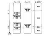
- FIG. 17 is an explanatory diagram showing call costs due to use of the OS.
- the thread immediately after the thread confirms the exclusive flag (time t1), when the flag is released by another CPU, or when the OS function is not used (in the case of the left diagram), the thread is time t2. You can get a flag and start processing using shared resources.
- the OS function in the case of the right diagram
- the OS returns to the thread processing after the interrupt is restored. Then, the processing is transferred to the OS again by the exclusive acquisition request from the thread, the OS acquires the exclusive right, and returns to the processing of the thread. The thread cannot start processing using the shared resource until.
- An object of the present invention is to provide an exclusive control method and an exclusive control program capable of reducing the overhead due to the OS in order to solve the above-described problems caused by the prior art.
- the exclusive thread accesses the shared resource until exclusive control is released.
- the exclusive control process for prohibiting the trial is executed by the operating system according to the number of attempts to access the shared resource of the exclusion target thread stored in the storage area, and is executed by any one of a plurality of threads.
- an exclusive control process is executed that causes the exclusion target thread to try until access to the shared resource is permitted, the remaining thread that is the exclusion target thread other than any one of the plurality of threads
- the number of attempts to access the shared resource is counted, and the counted number of attempts is counted by the remaining threads.
- Exclusive control method of storing in the storage area, and the exclusive control program is proposed.
- FIG. 1 is an explanatory diagram showing an example of the present invention.
- FIG. 2 is a block diagram of a hardware example of the multi-core processor system according to the embodiment.
- FIG. 3 is a block diagram illustrating an example of functions of the multi-core processor system 200.
- FIG. 4 is an explanatory diagram illustrating an example of generation of an exclusion flag.
- FIG. 5 is an explanatory diagram illustrating an example in which a thread executes a process related to a shared resource.
- FIG. 6 is an explanatory diagram showing an example when a timer interrupt occurs.
- FIG. 7 is an explanatory diagram showing an example of tri-locking.
- FIG. 8 is an explanatory diagram illustrating an example of the end of the exclusion process for the thread 231_1.
- FIG. 8 is an explanatory diagram illustrating an example of the end of the exclusion process for the thread 231_1.
- FIG. 9 is an explanatory diagram illustrating an example of the start of exclusive processing by the thread 231_2.
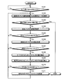
- FIG. 10 is a flowchart illustrating an example of an exclusive generation procedure by the OS and threads.
- FIG. 11 is a flowchart illustrating an example of a processing procedure when exclusive control is started by an OS and a thread.
- FIG. 12 is a flowchart illustrating an example of a processing procedure when the exclusive right is released by the OS and the thread.
- FIG. 13 is a flowchart illustrating an example of an exclusive control processing procedure when a timer interrupt is generated by the OS.
- FIG. 14 is an explanatory diagram illustrating an example of access to a shared resource in a multi-core processor system.
- FIG. 15 is an explanatory diagram illustrating an example of a spin lock.
- FIG. 16 is an explanatory diagram illustrating an example of a trilock.
- FIG. 17 is an explanatory diagram showing call costs due to use of the OS.
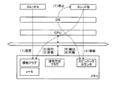
- FIG. 1 is an explanatory diagram showing an example of the present invention. Thread A and thread B share the variable x. Here, it is assumed that the state of the exclusive flag is empty and the exclusive method flag indicates spin lock.
- the thread A sets (1) the exclusive flag to use the variable x to access the variable x
- the thread A is permitted to access the variable x.
- the thread B acquires the exclusive flag to access the variable x
- the access to the variable x is prohibited because it has already been changed during use. That is, the thread B executes exclusive control processing by spin lock.
- the thread B (2) repeatedly acquires the exclusive flag until access to the variable x is permitted, and tries to determine whether the access is possible. For example, each time the thread B tries, (3) the number of trials is counted, and (4) the number of trials is stored in the spin lock counter.
- the OS detects (5) the value of the spin lock counter at a fixed timing. For example, the OS determines whether (6) the value of the spin lock counter is equal to or greater than a predetermined number of times. For example, when the value of the spin lock counter is equal to or greater than a predetermined number of times, the OS prohibits an attempt to access from the thread B by stopping the thread B (7).
- the exclusive control apparatus may be a single-core system or a multi-core processor system.
- the multi-core processor system will be described as an example.
- the multi-core processor is a processor in which a plurality of cores are mounted. If a plurality of cores are mounted, a single processor having a plurality of cores may be used, or a processor group in which single core processors are arranged in parallel may be used.
- a processor group in which single-core processors are arranged in parallel will be described as an example.
- FIG. 2 is a block diagram of a hardware example of the multi-core processor system according to the embodiment.
- the multi-core processor system 200 includes a CPU 201_1, a CPU 201_2, a CPU 201_3, a display 202, a keyboard 203, an I / F 204 (InterFace), a RAM 206 (Random Access Memory), and a ROM 207 (Read Only Memory). ing.
- the multi-core processor system 200 includes a flash ROM 208, a flash ROM controller 209, and a flash ROM 210.
- the CPUs 201_1 to 201_3, the display 202, the keyboard 203, the I / F 204, the RAM 206, the ROM 207, the flash ROM 208, and the flash ROM controller 209 are connected via a bus 211.
- the CPUs 201_1 to 201_3 each have a register, a core, and a cache.
- the core has a calculation function.
- the registers in each CPU have a PC (Program Counter) and a reset register.
- the CPU 201_1 is a master CPU, controls the entire multi-core processor system 200, and executes the OS 221_1.
- the OS 221_1 is a master OS and executes a thread assigned to the CPU 201_1.
- the OS 221_1 has a scheduler, and the scheduler has a function of controlling which CPU of the multi-core processors an application that has received a start instruction is assigned.
- the scheduler has a function of controlling the execution order of applications assigned to the CPU 201_1.
- the CPU 201_2 and the CPU 201_3 are slave CPUs, and execute the OS 221_2 and the OS 221_3, respectively.
- the OS 221_2 and the OS 221_3 are slave OSs, and execute threads assigned to the CPU 201_2 and the CPU 201_3, respectively.
- the OS 221_2 has a scheduler, and the scheduler has a function of controlling the execution order of applications assigned to the CPU 201_2.
- the OS 221_3 has a scheduler, and the scheduler has a function of controlling the execution order of applications assigned to the CPU 201_3.
- Threads 231_1 to 231_3 are threads related to the application A and share the same variables.
- the thread 231_1 is assigned to the CPU 201_1, the thread 231_2 is assigned to the CPU 201_2, and the thread 231_3 is assigned to the CPU 201_3.
- the display 202 displays data such as a document, an image, and function information as well as a cursor, an icon, or a tool box.
- a TFT liquid crystal display can be adopted.
- the keyboard 203 has keys for inputting numbers, various instructions, and the like, and inputs data.
- the keyboard 203 may be a touch panel type input pad or a numeric keypad.
- the I / F 204 is connected to a network 205 such as a LAN (Local Area Network), a WAN (Wide Area Network), and the Internet through a communication line, and is connected to another device via the network 205.
- the I / F 204 controls an internal interface with the network 205 and controls input / output of data from an external device.
- a modem or a LAN adapter may be employed as the I / F 204.
- the ROM 207 stores a program such as a boot program.
- the RAM 206 is used as a work area for each CPU.
- the flash ROM 208 stores system software such as the OSs 221_1 to 221_3 and application programs.
- the RAM 206 has a higher access speed from each CPU than the flash ROM 208.
- Each OS loads an application program from the flash ROM 208 to the RAM 206, whereby the context information of the application is expanded in the RAM 206.
- the flash ROM controller 209 controls reading / writing of data with respect to the flash ROM 210 according to the control of each CPU.
- the flash ROM 210 stores data written under the control of the flash ROM controller 209. Specific examples of the data include image data and video data acquired by the user using the multi-core processor system 200 through the I / F 204.
- As the flash ROM 210 for example, a memory card or an SD card can be adopted.
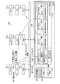
- FIG. 3 is a block diagram illustrating an example of functions of the multi-core processor system 200.
- the thread 231_m includes a counting unit 301 and a storage unit 302.
- the OS 221_n includes a detection unit 311, a calculation unit 312, a determination unit 313, an execution unit 314, a determination unit 315, and a change unit 316.
- the counting unit 301 and the storage unit 302 are coded in a thread 231_m, and the thread 231_m is stored in a storage device such as the flash ROM 208.
- the counting unit 301 and the storage unit 302 are executed.
- the detecting unit 311 to the changing unit 316 are coded in the OS 221_n, and the OS 221_n is stored in a storage device such as the flash ROM 208.
- the CPUs 201_1 to 201_3 read the OSs 221_1 to 221_3 from the storage devices, respectively, and execute the coded processing, whereby the changing unit 316 is executed from the detecting unit 311.
- the counting unit 301 counts the number of attempts of access to the shared resource by the remaining threads that are exclusive threads other than one of the threads.
- shared resources include RAM 206 shared by a plurality of CPUs, bus 211, and variables shared by applications.
- the second exclusive control process is, for example, an exclusive control process using a spin lock.
- the storage unit 302 stores the number of trials counted by the counting unit 301 in a storage area that can be referred to by the OS.
- the detecting unit 311 detects the number of attempts to access the shared resource of the exclusion target thread stored in the storage area.
- the determination unit 313 determines whether the number of trials detected by the detection unit 311 is a predetermined number or more.
- the calculation unit 312 calculates the average value of the number of attempts to access the shared resource for each remaining thread detected by the detection unit 311.
- the remaining threads store the average value calculated by the calculation unit 312 in the storage area.
- the execution unit 314 attempts to access the shared resource of the exclusion target thread until the exclusive control is released when the exclusion target thread accesses the shared resource. A first exclusive control process for prohibiting is executed.
- the determination unit 315 determines whether the elapsed time from the start of access of the exclusion target thread is equal to or longer than a predetermined time.
- the changing unit 316 cancels the prohibition on the attempt to access the shared resource of the exclusion target thread.
- the changing unit 316 continues to prohibit the trial of accessing the shared resource of the exclusion target thread. This will be described in detail based on the above.
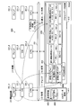
- FIG. 4 is an explanatory diagram showing an example of generation of an exclusion flag.
- the thread 231_1 secures (1) the area of the exclusion flag 403 and the area of the exclusion method flag 404 in the process data area 410 on the RAM 206.
- the RAM 206 has an OS data area 411 and a process data area 410. Data handled by each OS is stored in the OS data area 411, and data handled by each thread is stored in the process data area 410. Each thread cannot access the process data area 410.
- the thread 231_1 acquires (2) the total number of threads including the activation schedule of the application to which the thread 231_1 belongs from the table 400.
- the table 400 has fields for application name and total number of threads.
- application name application identification information is registered, and in the total thread number, the application total thread number of the identification information registered in the application name is registered.
- the thread 231_1 is a thread belonging to the application A, 3 is acquired as the total number of threads.
- the thread 231_1 secures (3) the wait start time register area for the acquired total thread count and the SC (spin lock counter) area for the total thread count in the process data area 410 on the RAM 206.
- SC 401_1 to 401_3 and waiting start time registers 402_1 to 402_3 are secured in the process data area 410.
- the thread 231_1 sets (4) the exclusive flag 403 to 0 (open state) and sets the exclusive method flag 404 to 0 (spin lock method).
- the thread 231_1 sets (5) 0 to SC401_1 to 401_3.
- the thread 231_1 notifies the OS 221_1 of the reference information 405 of all the reserved areas (6).
- the reference information 405 is information for referring to an area reserved in the process data area 410 from the OS 221_1.
- the reference information 405 is reserved for use when a thread accesses the reserved area. The start address of the area is described.
- the OS 221_1 when the OS 221_1 receives the reference information 405 from the thread 231_1, it generates exclusive identification information corresponding to the reference information 405.
- the exclusion identification information is information for identifying information regarding exclusion in which the thread 231_1 has secured the area.
- attention is focused on only one exclusive control process, but since there are actually a plurality of exclusive control processes, information for identifying each exclusive information is attached.
- the OS 221_1 registers (7) the exclusive identification information and the reference information 405 in the OS data area 411 in association with each other.
- the OS 221_1 when the OS 221_1 receives exclusive identification information from any thread, the OS 221_1 refers to the reference information 405 based on the received exclusive identification information.
- the OS 221_1 can access the data stored in the reserved area in the process data area 410 according to the head address described in the reference information 405.
- the OS 221_1 notifies the thread 231_1 of exclusive identification information. For example, when the thread 231_1 receives exclusive identification information from the OS 221_1, the exclusive identification information is recorded in association with the secured area.
- FIG. 5 is an explanatory diagram showing an example in which a thread executes a process related to a shared resource.
- the thread 231_1 checks the exclusion flag 403 by acquiring the state of the exclusion flag 403.
- the thread 231_1 changes the exclusive flag 403 from 0 (open state) to 1 (in use).
- the thread 231_1 sets 0 to SC401_1.
- the thread 231_2 checks the exclusion flag 403 by acquiring the state of the exclusion flag 403.
- the thread 231_2 checks the exclusive method flag 404 by acquiring the state of the exclusive method flag 404.
- the exclusion method flag 404 is 0 (spin lock)
- the thread 231_2 increments SC401_2.
- the value of SC becomes 1.
- the thread 231_2 repeats the check of the exclusion flag 403 and the check of the exclusion method flag 404. While the check of the exclusive flag 403 is 1 (in use) and the exclusive method flag 404 is 0 (spin lock), the thread 231_2 repeats incrementing the SC 401_2.
- the thread 231_3 checks the exclusion flag 403 by acquiring the state of the exclusion flag 403.
- the thread 231_3 checks the exclusion method flag 404 by acquiring the state of the exclusion method flag 404.
- the exclusion method flag 404 is 0 (spin lock)
- the thread 231_3 increments SC401_3.
- the value of SC becomes 1.
- the thread 231_3 repeats the check of the exclusion flag 403 and the check of the exclusion method flag 404.
- the thread 231_3 repeats incrementing the SC 401_3.
- FIG. 6 is an explanatory diagram showing an example when a timer interrupt occurs.
- the OS 221_1 receives a timer interrupt, for example, one exclusive identification information is selected from a plurality of exclusive identification information.
- the OS 221_1 checks the exclusion flag 403 by acquiring the state of the exclusion flag 403 based on (1) the reference information 405 of the selected exclusion identification information. For example, since the exclusive flag 403 is 1 (in use), the OS 221_1 checks the exclusive method flag 404 by acquiring the state of the (2) exclusive method flag 404.
- the OS 221_1 detects the value of the all spin lock counter.
- the OS 221_1 calculates (3) an average value of counter values other than 0.
- the value of SC401_1 is 0, the value of SC401_2 is 300, and the value of SC401_3 is 296, so the average value is 298.
- the OS 221_1 determines whether (4) the calculated average value is equal to or greater than a predetermined number of times.
- the predetermined number of times is 280. Since the calculated average value is equal to or greater than the predetermined number of times, for example, the OS 221_1 changes (5) the exclusion method flag 404 from 0 (spin lock) to 1 (tri lock).
- it is determined that the average value is equal to or greater than the predetermined number of times.
- the present invention is not limited to this. It may be a majority vote such as whether there are more than one.
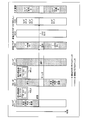
- FIG. 7 is an explanatory diagram showing an example of tri-locking.
- the thread 231_2 checks the exclusion flag 403 by acquiring the state of the exclusion flag 403.
- the thread 231_2 checks the exclusive method flag 404 by acquiring the state of the exclusive method flag 404.
- the exclusion method flag 404 is 1 (trilock)
- the thread 231_2 specifies exclusive identification information and requests the OS 221_2 to perform a trilock.
- the OS 221_2 registers the identification information of the thread 231_2 in the flag waiting queue 406 corresponding to the exclusive identification information received from the thread 231_2.
- the OS 221_2 acquires the current time and sets the current time in the waiting start time register 402_2 of the thread 231_2.
- the waiting start time register 402_2 becomes 15:00:10.
- the OS 221_2 performs rescheduling.
- the CPU 201_2 enters a waiting state.
- the thread 231_3 checks the exclusion flag 403 by acquiring the state of the exclusion flag 403.
- the thread 231_3 checks the exclusion method flag 404 by acquiring the state of the exclusion method flag 404.
- the thread 231_3 specifies exclusive identification information and requests the OS 221_3 for a trilock.
- the OS 221_3 registers the identification information of the thread 231_3 in the flag waiting queue 406 corresponding to the identification information received from the thread 231_3.
- the OS 221_3 obtains the current time and sets the current time in the waiting start time register 402_3 of the thread 231_3.
- the waiting start time register 402_3 is 15:00:11.
- the OS 221_3 performs rescheduling.
- the CPU 201_3 enters a waiting state.
- FIG. 8 is an explanatory diagram showing an example of the end of the exclusive processing of the thread 231_1.
- the thread 231_1 acquires the state of the exclusion method flag 404, thereby (1) checking the exclusion flag 403.
- the thread 231_1 designates (2) exclusion identification information and notifies the OS 221_1 of the release request.
- the OS 221_1 receives the release request notification, the current time is acquired.
- the OS 221_1 acquires (3) identification information of a thread registered in the flag waiting queue 406.
- identification information of each of the thread 231_2 and the thread 231_3 is acquired.
- the OS 221_1 detects the time from the thread wait start time register indicated by the acquired thread identification information. For example, the OS 221_1 calculates (4) a difference value (waiting time) between the current time and each acquired time. For example, the OS 221_1 calculates the average waiting time based on the obtained difference value for each time.
- the current time is 15:10:20.
- the value of the waiting start time register 402_2 is 15:10:10
- the value of the waiting start time register 402_3 is 15:10:11.
- the average waiting time is 9.5 [seconds].
- the OS 221_1 determines whether (5) the calculated average waiting time is equal to or shorter than a predetermined time.
- the predetermined time is 3 [seconds]. Since the calculated average waiting time is not less than or equal to the predetermined time, the tri-lock remains unchanged. Here, it is determined whether or not the average waiting time is equal to or less than the predetermined time.
- the present invention is not limited to this, and it may be determined whether or not the median waiting time is equal to or less than the predetermined time. You may judge by the majority vote of how many the time is below predetermined time.
- the tri-lock is changed to the spin lock.
- the OS 221_1 changes (6) the exclusive flag 403 from 1 (in use) to 0 (open state). For example, the OS 221_1 resumes the execution of the thread 231_2 in which the identification information is registered at the head of the (7) flag waiting queue.
- FIG. 9 is an explanatory diagram showing an example of starting exclusive processing by the thread 231_2.
- the thread 231_2 checks the exclusion flag 403 by acquiring the state of the exclusion flag 403.
- the thread 231_2 checks the exclusive method flag 404 by acquiring the state of the exclusive method flag 404.
- the exclusion method flag 404 is 1 (trilock)
- the thread 231_2 specifies exclusive identification information and requests the OS 221_2 to perform a trilock.
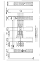
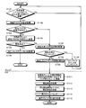
- FIG. 10 is a flowchart illustrating an example of an exclusive generation procedure by the OS and threads.
- the thread secures an exclusive flag and an exclusive method flag area (step S1001), acquires the total number of threads including the activation schedule (step S1002), and reserves a spin lock counter and a waiting start time register area for the total number of threads. (Step S1003).
- the thread sets the exclusive flag to an open state (step S1004), and sets the exclusive method flag to spin lock (step S1005).
- the spin lock is set, but the tri lock may be set.
- the thread sets all the spin lock counters to 0 (step S1006), and notifies the OS of reference information for all the reserved areas (step S1007).
- the OS When the OS receives the reference information, it generates exclusive identification information related to the reference information (step S1008), records the exclusive identification information and the reference information (step S1009), and sets the exclusive identification information as the reference information notification source. The thread is notified (step S1010). When the thread receives exclusive identification information, the identification information is recorded (step S1011), and the series of processing ends.
- FIG. 11 is a flowchart showing an example of a processing procedure when exclusive control is started by the OS and threads. It is determined whether the thread accesses the shared resource or returns from the waiting state (step S1101). When it is determined that the thread has not started access to the shared resource and has not returned from the wait state (step S1101: No), the process returns to step S1101.
- step S1102 If the thread determines that the shared resource has been accessed or has returned from the wait state (step S1101: Yes), the exclusive flag state is acquired (step S1102), and whether the exclusive flag state is in use. Is determined (step S1103). If the thread determines that the state of the exclusive flag is not in use (step S1103: No), the exclusive flag is changed to being used by a special instruction (step S1104). The thread determines whether or not the change is successful (step S1105). If it is determined that the change is successful (step S1105: Yes), the spin lock counter is set to 0 (step S1106).
- step S1103 When the thread determines that the state of the exclusive flag is in use (step S1103: Yes), or determines that the change has not been successful (step S1105: No), the state of the exclusive method flag is acquired (step S1103). S1107).
- the thread determines whether or not the exclusion method is spin lock (step S1108). If the thread determines that the exclusion method is spin lock (step S1108: Yes), the spin lock counter is incremented (step S1110), and the process returns to step S1101.
- step S1108: No it designates exclusion identification information and notifies a trilock request (step S1109).
- step S1109 when the OS accepts a trilock request from a thread, the OS registers the identification information of the requesting thread in the flag waiting queue corresponding to the exclusive identification information (step S1111).
- the OS acquires the current time (step S1112), and records the current time in the waiting start time register (step S1113).
- the OS reschedules (step S1114) and executes an execution thread switching process (step S1115).
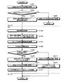
- FIG. 12 is a flowchart showing an example of a processing procedure when an exclusive right is released by an OS and a thread.
- the thread acquires the state of the exclusion method flag (step S1201), and determines whether or not the exclusion method is spin lock (step S1202). If the thread determines that the exclusion method is spin lock (step S1202: Yes), the exclusion flag is changed to an empty state (step S1203), and the series of processing ends.
- step S1202 When the thread determines that the exclusion method is not spin lock (step S1202: No), it designates exclusive identification information and notifies the OS of a release request (step S1204).
- the OS receives the release request from the thread, the OS acquires the current time (step S1205).
- the OS acquires all the thread identification information from the flag waiting queue corresponding to the exclusive identification information (step S1206).
- the OS acquires the waiting start time of the thread indicated by the identification information registered in the flag waiting queue (step S1207), calculates the average waiting time (step S1208), and whether the average waiting time is equal to or less than a predetermined time. It is determined whether or not (step S1209).
- step S1209: Yes the state of the exclusive method flag is changed to spin lock (step S1210).
- the OS changes the exclusive flag to an empty state (step S1211), restarts all the threads indicated by the identification information registered in the flag waiting queue (step S1212), and ends the series of processes.
- the exclusive flag is changed to an open state (step S1213).
- the OS resumes the thread indicated by the identification information registered at the head of the flag waiting queue (step S1214), and the series of processing ends.
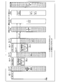
- FIG. 13 is a flowchart showing an example of an exclusive control processing procedure when a timer interrupt is generated by the OS.
- the OS determines whether a timer interrupt has been accepted (step S1301). If the OS determines that the timer interrupt has not been accepted (step S1301: No), the process returns to step S1301. If the OS determines that the timer interrupt has been accepted (step S1301: Yes), one unselected one is selected from the registered exclusive information (step S1302). The OS determines whether there is no selectable exclusive information (step S1303).
- step S1303 determines whether there is no selectable exclusion information (step S1303: No). If the OS does not determine that there is no selectable exclusion information (step S1303: No), the state of the exclusion flag is acquired (step S1304). The OS determines whether or not the exclusive flag is in use (step S1305). If the OS determines that the exclusive flag is not in use (step S1305: No), the process returns to step S1302.
- step S1305 determines that the state of the exclusion flag is in use (step S1305: Yes)
- step S1305 determines that the state of the exclusion flag is in use (step S1305: Yes)
- step S1306 the state of the exclusion method flag is acquired (step S1306), and it is determined whether or not the exclusion method is spin lock (step S1306).
- step S1307 the process returns to step S1302.
- step S1307 When the OS determines that the exclusion method is spin lock (step S1307: Yes), it acquires the values of all spin lock counters (step S1308). The OS calculates the average value of the spin lock counters other than 0 (step S1309), and determines whether the average value is equal to or greater than the predetermined number of times (step S1310).
- step S1310: No When the OS determines that the average value is not equal to or greater than the predetermined number (step S1310: No), the process returns to step S1302.
- step S1310: Yes the exclusive lock flag is set to trilock (step S1311), and the process proceeds to step S1302.
- step S1303 when the OS determines that there is no selectable exclusive information (step S1303: Yes), the series of processing ends. In addition, the processing related to exclusive control ends, but the OS performs normal timer interrupt processing.
- the OS Exclusive control processing with a trilock is executed.
- the OS can perform spin lock without calling the OS.
- switching between methods can be easily performed by managing, with the exclusion method flag, which exclusion lock processing is used for each exclusion target thread by using the exclusion lock process.
- the OS secures a storage area for storing the exclusion method flag in a recording area accessible to the exclusion target thread, so that the exclusion target thread can perform spin lock without calling the OS.
- the exclusive control process with the trilock by the OS is executed and the elapsed time from the access start time when the exclusion target thread accesses the shared resource is less than the predetermined time, the exclusive control process with the spin lock by the thread is executed. Is done.
- exclusive control processing with spin lock can be performed on the shared resource.
- realizing the spin lock without using the function of the OS it is possible to shorten the overhead from when the shared resource is released until the exclusive right is acquired by another thread. Also, by not calling the OS at the time of spin lock, the number of data swaps in the cache can be reduced.
- the exclusive control process with the trilock by the OS is continuously executed. Thereby, when it takes time to release the exclusive right of the shared resource, it is possible to perform exclusive control processing with a trilock on the shared resource.
- the exclusive control method described in the present embodiment can be realized by executing a prepared exclusive control program on a computer such as a personal computer or a workstation.
- the exclusive control program is recorded on a computer-readable recording medium such as a hard disk, a flexible disk, a CD-ROM, an MO, and a DVD, and is executed by being read from the recording medium by the computer.
- the exclusive control program may be distributed via a network such as the Internet.
Landscapes
- Engineering & Computer Science (AREA)
- Software Systems (AREA)
- Theoretical Computer Science (AREA)
- Physics & Mathematics (AREA)
- General Engineering & Computer Science (AREA)
- General Physics & Mathematics (AREA)
- Debugging And Monitoring (AREA)
- Multi Processors (AREA)
Abstract
スレッド(A)が(1)変数xへアクセスするために排他フラグを利用中に設定すると、スレッド(A)から変数xへのアクセスが許可される。スレッド(B)が、変数xへアクセスするために排他フラグを取得すると、すでに利用中に変更されているため、変数xへのアクセスが禁止される。スレッド(B)が、(2)変数xへのアクセスが許可されるまで排他フラグの取得を繰り返し、アクセス可能か否かを試行する都度、(3)試行回数を計数し、(4)スピンロックカウンタに試行回数を格納する。OSが、一定のタイミングで、(5)スピンロックカウンタの値を検出する。OSが、(6)スピンロックカウンタの値が所定回数以上であるか否かを判断する。OSが、スピンロックカウンタの値が所定回数以上である場合、排他方式フラグをトライロックに変更し、(7)スレッド(B)を停止させることにより、スレッド(B)からのアクセスの試行を禁止する。
Description
本発明は、共有資源へのアクセスを制御する排他制御方法、および排他制御プログラムに関する。
マルチコアプロセッサシステムもしくはマルチタスクOS(Operating System)を搭載したシングルプロセッサシステムでは複数のプロセスまたはスレッドが同時に動作することができる。
ここで、たとえば、スレッド#0とスレッド#1の二つのスレッドが同時にメモリ上の変数xに1を足そうとする。変数xに1を足すという処理は、CPU(Central Processing Unit)のオペレーションのレベルではメモリから変数xの値を読み込んで、読み込んだ値に1を足して、足した結果をメモリ上の変数xに書き込むという3ステップで行われる。
図14は、マルチコアプロセッサシステムでの共有資源へのアクセス例を示す説明図である。マルチコアプロセッサシステムにおいて、たとえば、スレッド#0とスレッド#1がそれぞれCPU#0とCPU#1で同時に実行されているとする。時刻t1でスレッド#0がメモリから変数xの値をLoad命令で読み込んだ時点では変数xの値は0とする。読み込まれた変数xの値はCPU内のレジスタR1に格納されて時刻t2でレジスタR1に1が足され、足された結果がレジスタR1に格納される。時刻t2でCPU#1ではスレッド#1が実行されていて、スレッド#1で同じくLoad命令で変数xの値を読み込む。変数xの値は0であるので、CPU#1のレジスタR2には0が格納される。
・時刻t1:R1=x=0
・時刻t2:R1=R1+1=1、R2=x=0
・時刻t2:R1=R1+1=1、R2=x=0
時刻t3でスレッド#0がレジスタR1の値をメモリの変数xに書き込む。さらに、時刻t4でスレッド#1がR2に1を足した結果を書き込むが、該足した結果は1のため、変数xには再度1が書き込まれる。
・時刻t3:x=R1=1、R2=R2+1=1
・時刻t4:x=R2=1
・時刻t4:x=R2=1
このように、スレッド#0が変数xに1を足した結果を書き込む前にスレッド#1が変数xの値をメモリから読み込んでしまうと、変数xに2回1を足したにも関わらず、結果として変数xの値が1しか増えていないことになる問題が生じる。シングルプロセッサシステムでも、マルチタスクOSの場合は複数のプロセスもしくはスレッドが時分割的に実行されるため、同様の問題が生じる。
そのため、共有するメモリ上のデータやDMA(Direct Memory Access)等のハードウェアデバイスといった共有資源を複数のプロセスもしくはスレッドで利用する場合は排他制御を行わなければならない。排他制御ではメモリ上に置かれた排他フラグをCPUが提供するスワップや排他ロードストアといった特殊命令を利用して更新することで、排他フラグに関連付けられた共有資源が利用中であるか否かを管理する。
特殊命令で書き込みを行った場合は複数のCPUが同時に同じフラグに値を書き込もうとした場合に、一つのCPUしか書き込みを成功させることができない。特殊命令でフラグに書き込みを行った後で、特殊命令の結果を確認して排他フラグに利用中を示す値を書き込んだスレッドのみが対象の共有資源へのアクセス権を獲得出来たことになる。もしくは、シングルプロセッサシステムであればOSに排他フラグの更新を行わせることで特殊命令を利用しなくても排他制御が可能になる。アクセス権を獲得したスレッドは共有資源の利用が終了したら時刻t2で排他フラグに開放を示す値を書き込むことで共有資源の利用終了を宣言する。
アクセス権を獲得出来なかったスレッドは、アクセス権を獲得したスレッドが共有資源の利用を終了してアクセス権を開放するまで待たなければならない。ここで、アクセス権を獲得できなかったスレッドが、アクセス権を開放するまで待つ方式として、スピンロックとトライロックの2つの方式が知られている。
図15は、スピンロックの一例を示す説明図である。図15で示すように、スピンロックでは、アクセス権を獲得できなかったスレッドが、排他フラグの値が開放を示す値になるまで排他獲得処理を繰り返す。スピンロックでは、排他制御によりアクセス権を獲得したスレッドは、共有資源の利用が完了したら排他フラグに開放中を示す値を書き込むことで共有資源の利用完了を宣言する。
図15では、スレッド#1が時刻t1で先に排他権を獲得したため、スレッド#0は時刻t2で排他権の獲得に失敗し、排他権の獲得の試行を繰り返す。時刻t3でスレッド#1が排他権を開放するため、スレッド#0では時刻t4での直後の排他権の獲得試行で成功することができる。
図16は、トライロックの一例を示す説明図である。図16で示すように、トライロックでは、アクセス権が開放されるまで、アクセス権を獲得できなかったスレッドの実行が停止される。トライロックの場合は、共有資源の利用が完了したら排他フラグを開放中に変更すると共にOSにアクセス権の開放を通知する。アクセス権が開放されたらOSは停止していたスレッドの実行を再開する。
図16では、時刻t1でスレッド#0が排他権の獲得を試みるが、既にスレッド#1により排他フラグが利用中になっていたとすると、OSによりスレッド#0は待ち状態に変更されて代わりに別のスレッド(ここではスレッド#1)に実行権が移る。その後、スレッド#1がこのフラグを開放すると、また、OSによりスレッド#0が実行可能な状態に変更される。
スピンロックでは、共有資源が開放されるまで繰り返し排他フラグを確認するため、共有資源が長時間開放されない場合はCPUの処理能力を無駄遣いする恐れがある。トライロックの場合は共有資源が開放されるまでスレッドの実行を停止するため、該スレッドの実行が停止されている間に他のスレッドを実行したり、実行可能なスレッドが無ければCPUを停止したりするといったことでCPUの処理能力を無駄遣いすることは無い。しかしながら、OSによるスレッドの停止/再開処理のためにオーバーヘッドが発生し、複数スレッドが動作している場合、動作再開後即座にスレッドが実行可能となる保障もないため、共有資源が利用可能になってから実際に利用を開始するまでにオーバーヘッドが発生することになる。
したがって、短時間で開放される共有資源に対してはスピンロックで排他制御処理を行い、開放までに時間がかかる共有資源に対してはトライロックで排他制御処理を行うのがよい。しかしながら、共有資源の開放までの待ち時間は資源の状態や利用しているスレッド数などによっても変わってくるため、一意に決めることは難しい。
そこで、排他解除までの待ち時間を統計情報として記録して実行時に適した排他方式に切り替える技術が知られている(たとえば、下記特許文献1参照。)。また、実行時に排他解除までの統計情報を記録し(たとえば、下記特許文献2参照。)、実行時に排他方式を切り替える(たとえば、下記特許文献3参照。)技術が知られている。
しかしながら、従来技術では排他制御でOSを利用する際の呼び出しコストについては考慮されていないという問題点がある。スピンロックで単純に排他フラグを確認するだけの処理は通常は数命令程度で実現でき、メモリアクセスのコストを考慮しても数十~数百[ナノ秒]程度で一回の排他フラグの確認を行うことができる。
しかしながら、排他フラグの更新をOSで行う場合は排他フラグを確認するためにOSを呼び出さなければならない。アプリケーションプログラムからOSの処理を呼び出すためには割り込みを使ってCPUを特権モードに遷移させるなどの処理が行われるため、数十[μ秒]~数百[μ秒]とフラグの確認処理よりも遙かに多くの時間がかかる。
図17は、OSの利用による呼び出しコストを示す説明図である。図17のように、スレッドが排他フラグを確認した直後(時刻t1)、別のCPUによりフラグが開放された場合、OSの機能を利用しない場合(左側の図の場合)にはスレッドが時刻t2でフラグを獲得して共有資源を使った処理を開始できる。しかしながら、OSの機能を利用した場合(右側の図の場合)は、OSが割り込みの復帰を行ってからスレッドの処理に戻る。そして、スレッドからの再度排他獲得要求によりOSに処理が移って、OSが排他権を獲得して、またスレッドの処理に戻るなど、OSとスレッドの処理実行を行き来することになり、時刻t2’になるまでスレッドが共有資源を利用した処理を開始できない。
たとえば、従来技術のように、トライロックによる排他制御処理とスピンロックによる排他制御処理をOSが切り替えると、OSとスレッドの実行を行き来するために、OSによるオーバーヘッドが生じる問題点があった。
本発明は、上述した従来技術による問題点を解消するため、OSによるオーバーヘッドを削減することができる排他制御方法、および排他制御プログラムを提供することを目的とする。
上述した課題を解決し、目的を達成するため、本発明の一の側面によれば、排他対象スレッドが共有資源へアクセスすると排他制御が解除されるまで前記排他対象スレッドの前記共有資源へのアクセスの試行を禁止する排他制御処理を、記憶領域に格納された前記排他対象スレッドの前記共有資源へのアクセスの試行回数に応じて、オペレーティングシステムが実行し、複数のスレッドのうちいずれかのスレッドにより、前記排他対象スレッドに前記共有資源へのアクセスが許可されるまで試行させる排他制御処理を実行した場合、前記複数のスレッドのうち前記いずれかのスレッド以外の前記排他対象スレッドとなる残余のスレッドにより、前記共有資源へのアクセスの試行回数を計数し、計数された試行回数を前記残余のスレッドにより、前記記憶領域に格納する排他制御方法、および排他制御プログラムが提案される。
本発明の一の側面によれば、OSによるオーバーヘッドを削減することができるという効果を奏する。
以下に添付図面を参照して、本発明にかかる排他制御方法、および排他制御プログラムの実施の形態を詳細に説明する。
図1は、本発明の一例を示す説明図である。スレッドAとスレッドBとが変数xを共有している。ここでは、排他フラグの状態が空きであり、排他方式フラグがスピンロックを示していることとする。
たとえば、スレッドAが、(1)変数xへアクセスするために排他フラグを利用中に設定すると、スレッドAから変数xへのアクセスが許可される。スレッドBが、変数xへアクセスするために排他フラグを取得すると、すでに利用中に変更されているため、変数xへのアクセスが禁止される。すなわち、スレッドBがスピンロックによる排他制御処理を実行する。スレッドBが、(2)変数xへのアクセスが許可されるまで排他フラグの取得を繰り返し、アクセス可能か否かを試行する。スレッドBが、たとえば、試行する都度、(3)試行回数を計数し、(4)スピンロックカウンタに試行回数を格納する。
たとえば、OSが、一定のタイミングで、(5)スピンロックカウンタの値を検出する。たとえば、OSが、(6)スピンロックカウンタの値が所定回数以上であるか否かを判断する。たとえば、OSが、スピンロックカウンタの値が所定回数以上である場合、(7)スレッドBを停止させることにより、スレッドBからのアクセスの試行を禁止する。
本排他制御装置はシングルコアシステムであってもマルチコアプロセッサシステムであってもよいが、本実施の形態ではマルチコアプロセッサシステムを例に挙げて説明する。ここで、マルチコアプロセッサシステムにおいて、マルチコアプロセッサとは、コアが複数搭載されたプロセッサである。コアが複数搭載されていれば、複数のコアが搭載された単一のプロセッサでもよく、シングルコアのプロセッサが並列されているプロセッサ群でもよい。なお、本実施の形態では、説明を単純化するため、シングルコアのプロセッサが並列されているプロセッサ群を例に挙げて説明する。
(マルチコアプロセッサシステムのハードウェア例)
図2は、実施の形態にかかるマルチコアプロセッサシステムのハードウェア例を示すブロック図である。マルチコアプロセッサシステム200は、CPU201_1と、CPU201_2と、CPU201_3と、ディスプレイ202と、キーボード203と、I/F204(InterFace)と、RAM206(Random Access Memory)と、ROM207(Read Only Memory)と、を有している。マルチコアプロセッサシステム200は、フラッシュROM208と、フラッシュROMコントローラ209と、フラッシュROM210と、を有している。
図2は、実施の形態にかかるマルチコアプロセッサシステムのハードウェア例を示すブロック図である。マルチコアプロセッサシステム200は、CPU201_1と、CPU201_2と、CPU201_3と、ディスプレイ202と、キーボード203と、I/F204(InterFace)と、RAM206(Random Access Memory)と、ROM207(Read Only Memory)と、を有している。マルチコアプロセッサシステム200は、フラッシュROM208と、フラッシュROMコントローラ209と、フラッシュROM210と、を有している。
CPU201_1~201_3と、ディスプレイ202と、キーボード203と、I/F204と、RAM206と、ROM207と、フラッシュROM208と、フラッシュROMコントローラ209とは、バス211を介して接続されている。
ここで、CPU201_1~201_3は、それぞれレジスタとコアとキャッシュを有している。コアは、演算機能を有している。各CPU内のレジスタは、PC(Program Counter)やリセットレジスタを有している。
CPU201_1はマスタCPUであり、マルチコアプロセッサシステム200の全体の制御を司り、OS221_1を実行する。OS221_1はマスタOSであり、CPU201_1に割り当てられたスレッドを実行する。OS221_1はスケジューラを有し、スケジューラは起動指示を受け付けたアプリケーションをマルチコアプロセッサのうちのいずれのCPUに割り当てるかを制御する機能を有している。スケジューラはCPU201_1に割り当てられたアプリケーションの実行順序を制御する機能を有する。
CPU201_2とCPU201_3はスレーブCPUであり、それぞれOS221_2とOS221_3を実行する。OS221_2とOS221_3はスレーブOSであり、それぞれCPU201_2とCPU201_3に割り当てられたスレッドを実行する。OS221_2はスケジューラを有し、スケジューラはCPU201_2に割り当てられたアプリケーションの実行順序を制御する機能を有する。OS221_3はスケジューラを有し、スケジューラはCPU201_3に割り当てられたアプリケーションの実行順序を制御する機能を有する。スレッド231_1~231_3はアプリAに関するスレッドであり、同一の変数を共有することとする。スレッド231_1はCPU201_1に割り当てられ、スレッド231_2はCPU201_2に割り当てられ、スレッド231_3はCPU201_3に割り当てられている。
ディスプレイ202は、カーソル、アイコンあるいはツールボックスをはじめ、文書、画像、機能情報などのデータを表示する。ディスプレイ202は、たとえば、TFT液晶ディスプレイなどを採用することができる。キーボード203は、数字、各種指示などの入力のためのキーを有し、データの入力を行う。また、キーボード203は、タッチパネル式の入力パッドやテンキーなどであってもよい。
I/F204は、通信回線を通じてLAN(Local Area Network)、WAN(Wide Area Network)、インターネットなどのネットワーク205に接続され、ネットワーク205を介して他の装置に接続される。そして、I/F204は、ネットワーク205と内部のインターフェースを司り、外部装置からのデータの入出力を制御する。I/F204には、たとえばモデムやLANアダプタなどを採用することができる。
ROM207は、ブートプログラムなどのプログラムを記憶している。RAM206は、各CPUのワークエリアとして使用される。フラッシュROM208は、OS221_1~221_3などのシステムソフトウェアやアプリケーションのプログラムを記憶している。RAM206はフラッシュROM208よりも各CPUからのアクセス速度が速い。各OSがアプリケーションのプログラムをフラッシュROM208からRAM206へロードすることにより、該アプリケーションのコンテキスト情報がRAM206内に展開される。
フラッシュROMコントローラ209は、各CPUの制御に従ってフラッシュROM210に対するデータのリード/ライトを制御する。フラッシュROM210は、フラッシュROMコントローラ209の制御で書き込まれたデータを記憶する。データの具体例としては、マルチコアプロセッサシステム200を使用するユーザがI/F204を通して取得した画像データ、映像データなどである。フラッシュROM210は、たとえば、メモリカード、SDカードなどを採用することができる。
(マルチコアプロセッサシステム200の機能例)
図3は、マルチコアプロセッサシステム200の機能例を示すブロック図である。マルチコアプロセッサシステム200は、スレッド231_m(m=1~3)と、OS221_n(n=1~3)と、を有している。スレッド231_mは、計数部301と格納部302とを有している。OS221_nは、検出部311と、算出部312と、判断部313と、実行部314と、判断部315と、変更部316と、を有している。
図3は、マルチコアプロセッサシステム200の機能例を示すブロック図である。マルチコアプロセッサシステム200は、スレッド231_m(m=1~3)と、OS221_n(n=1~3)と、を有している。スレッド231_mは、計数部301と格納部302とを有している。OS221_nは、検出部311と、算出部312と、判断部313と、実行部314と、判断部315と、変更部316と、を有している。
計数部301と格納部302はスレッド231_mにコーディングされており、スレッド231_mはフラッシュROM208などの記憶装置に記憶されている。CPU201_1~201_3のいずれかのCPUが記憶装置からスレッド231_mを読み出し、コーディングされている処理を実行することにより、計数部301と格納部302が実行される。検出部311から変更部316はOS221_nにコーディングされており、OS221_nはフラッシュROM208などの記憶装置に記憶されている。CPU201_1~201_3が記憶装置からそれぞれOS221_1~221_3を読み出し、コーディングされている処理を実行することにより、検出部311から変更部316が実行される。
まず、複数のスレッドのうちいずれかのスレッドが、排他対象スレッドに共有資源へのアクセスが許可されるまで試行させる第2の排他制御処理を実行した場合である。計数部301は、複数のスレッドのうち、いずれかのスレッド以外の排他対象スレッドとなる残余のスレッドが共有資源へのアクセスの試行回数を計数する。
ここで、共有資源としては、たとえば、複数のCPUで共有するRAM206、バス211やアプリケーションで共有する変数が挙げられる。ここで、第2の排他制御処理は、たとえば、スピンロックによる排他制御処理である。格納部302は、計数部301によって計数された試行回数をOSが参照可能な記憶領域に格納する。
検出部311は、記憶領域に格納された排他対象スレッドの共有資源へのアクセスの試行回数を検出する。判断部313は、検出部311によって検出された試行回数が所定回数以上であるか否かを判断する。算出部312は、残余のスレッドが複数ある場合、検出部311によって検出された残余のスレッドごとの共有資源へのアクセスの試行回数の平均値を算出する。格納部302は、算出部312によって算出された平均値を残余のスレッドが記憶領域に格納する。
実行部314は、判断部313によって試行回数が所定回数以上であると判断された場合、排他対象スレッドが共有資源へアクセスすると排他制御が解除されるまで排他対象スレッドの共有資源へのアクセスの試行を禁止する第1の排他制御処理を実行する。
また、排他対象スレッドが共有資源へアクセスすると排他制御が解除されるまで排他対象スレッドの共有資源へのアクセスの試行を禁止する第1の排他制御処理を実行した場合において説明する。判断部315は、排他対象スレッドのアクセス開始からの経過時間が所定時間以上であるか否かを判断する。
変更部316は、判断部315によって経過時間が所定時間以上でないと判断された場合、排他対象スレッドの共有資源へのアクセスの試行の禁止を解除する。変更部316は、判断部315によって経過時間が所定時間以上でないと判断された場合、排他対象スレッドの共有資源へのアクセスの試行の禁止を継続する。以上を踏まえて詳細に説明する。
図4は、排他フラグの生成例を示す説明図である。まず、具体的には、たとえば、スレッド231_1が、(1)排他フラグ403の領域と排他方式フラグ404との領域をRAM206上のプロセスデータ領域410に確保する。ここで、RAM206上はOSデータ領域411とプロセスデータ領域410とを有している。各OSが取り扱うデータがOSデータ領域411に格納され、各スレッドが取り扱うデータがプロセスデータ領域410に格納される。各スレッドはプロセスデータ領域410にアクセスできない。
たとえば、スレッド231_1が、(2)スレッド231_1が属するアプリケーションの起動予定を含めた総スレッド数をテーブル400から取得する。テーブル400は、アプリ名、総スレッド数のフィールドを有する。アプリ名にはアプリケーションの識別情報が登録され、総スレッド数には、アプリ名に登録された識別情報のアプリケーションの総スレッド数が登録されている。ここでは、スレッド231_1はアプリAに属するスレッドであるため、総スレッド数として3が取得される。
たとえば、スレッド231_1が、(3)取得した総スレッド数分の待ち開始時刻レジスタの領域と総スレッド数分のSC(スピンロックカウンタ)の領域をRAM206上のプロセスデータ領域410に確保する。図4では、SC401_1~401_3と、待ち開始時刻レジスタ402_1~402_3がプロセスデータ領域410内に確保されている。
たとえば、スレッド231_1が、(4)排他フラグ403を0(開放状態)に設定し、排他方式フラグ404を0(スピンロック方式)に設定する。たとえば、スレッド231_1が、(5)SC401_1~401_3に0を設定する。たとえば、スレッド231_1が、(6)確保したすべての領域の参照情報405をOS221_1に通知する。ここで、参照情報405とはOS221_1からプロセスデータ領域410に確保された領域を参照するための情報であり、参照情報405には、該確保された領域にスレッドがアクセスする際に用いる確保された領域の先頭アドレスが記述されている。
たとえば、OS221_1が、スレッド231_1から参照情報405を受け付けると、参照情報405に対応する排他の識別情報を生成する。排他の識別情報は、スレッド231_1が領域を確保した排他に関する情報を識別するための情報である。本実施の形態では1つの排他制御処理のみに着目しているが、実際には複数の排他制御処理があるため、各排他に関する情報に識別するための情報が付される。たとえば、OS221_1が、(7)排他の識別情報と参照情報405とを関連付けてOSデータ領域411に登録する。たとえば、OS221_1が、いずれかのスレッドから排他の識別情報を受け付けると、受け付けた排他の識別情報に基づいて参照情報405を参照する。たとえば、OS221_1が、参照情報405に記述されている先頭アドレスに応じてプロセスデータ領域410内の確保された領域に記憶されているデータにアクセスすることができる。つぎに、たとえば、OS221_1が、排他の識別情報をスレッド231_1に通知する。たとえば、スレッド231_1が、OS221_1から排他の識別情報を受け付けると、排他の識別情報を、確保された領域と関連付けて記録する。
図5は、スレッドが共有資源に関する処理を実行する例を示す説明図である。たとえば、スレッド231_1が、排他フラグ403の状態を取得することにより、排他フラグ403をチェックする。ここでは、排他フラグ403が0であるため、たとえば、スレッド231_1が、排他フラグ403を0(開放状態)から1(利用中)に変更する。たとえば、スレッド231_1が、SC401_1に0を設定する。
たとえば、スレッド231_2が、排他フラグ403の状態を取得することにより、排他フラグ403をチェックする。ここでは、排他フラグ403が1(利用中)であるため、スレッド231_2が、排他方式フラグ404の状態を取得することにより、排他方式フラグ404をチェックする。ここでは、排他方式フラグ404が0(スピンロック)であるため、スレッド231_2が、SC401_2をインクリメントする。これにより、SCの値が1となる。そして、スレッド231_2が、排他フラグ403のチェックと排他方式フラグ404のチェックを繰り返す。排他フラグ403のチェックが1(利用中)であり、排他方式フラグ404が0(スピンロック)である間、スレッド231_2がSC401_2のインクリメントを繰り返す。
たとえば、スレッド231_3が、排他フラグ403の状態を取得することにより、排他フラグ403をチェックする。ここでは、排他フラグ403が1(利用中)であるため、スレッド231_3が、排他方式フラグ404の状態を取得することにより、排他方式フラグ404をチェックする。ここでは、排他方式フラグ404が0(スピンロック)であるため、スレッド231_3が、SC401_3をインクリメントする。これにより、SCの値が1となる。そして、スレッド231_3が、排他フラグ403のチェックと排他方式フラグ404のチェックを繰り返す。排他フラグ403のチェックが1(利用中)であり、排他方式フラグ404が0(スピンロック)である間、スレッド231_3がSC401_3のインクリメントを繰り返す。
図6は、タイマ割り込みの発生時の例を示す説明図である。OS221_1が、タイマ割り込みを受け付けると、たとえば、複数の排他の識別情報から、一の排他の識別情報を選択する。たとえば、OS221_1が、(1)選択した一の排他の識別情報の参照情報405に基づいて排他フラグ403の状態を取得することにより、排他フラグ403をチェックする。たとえば、排他フラグ403が1(利用中)であるため、OS221_1が、(2)排他方式フラグ404の状態を取得することにより、排他方式フラグ404をチェックする。
たとえば、排他方式フラグ404が0(スピンロック)であるため、OS221_1が、全スピンロックカウンタの値を検出する。OS221_1が、(3)値が0以外のカウンタの値の平均値を算出する。ここでは、SC401_1の値は0であり、SC401_2の値は300であり、SC401_3の値は296であるため、平均値が298である。たとえば、OS221_1が、(4)算出した平均値が所定回数以上であるか否かを判断する。ここでは、所定回数を280とする。算出された平均値が所定回数以上であるため、たとえば、OS221_1が、(5)排他方式フラグ404を0(スピンロック)から1(トライロック)に変更する。ここでは、平均値が所定回数以上であると判断しているが、これに限らず、たとえば、中央値が所定回数以上であるか判断してもよいし、所定回数以上のカウンタの値が複数個以上あるかなどの多数決であってもよい。
図7は、トライロックされる例を示す説明図である。たとえば、スレッド231_2が、排他フラグ403の状態を取得することにより、排他フラグ403をチェックする。ここでは、排他フラグ403が1(利用中)であるため、スレッド231_2が、排他方式フラグ404の状態を取得することにより、排他方式フラグ404をチェックする。ここでは、排他方式フラグ404が1(トライロック)であるため、スレッド231_2が、排他の識別情報を指定してトライロックをOS221_2に依頼する。
OS221_2が、スレッド231_2から受け付けた排他の識別情報に対応するフラグ待ちキュー406にスレッド231_2の識別情報を登録する。OS221_2が、現在時刻を取得し、スレッド231_2の待ち開始時刻レジスタ402_2に現在時刻を設定する。待ち開始時刻レジスタ402_2は、15:00:10となる。OS221_2が、再スケジューリングを行う。ここでは、CPU201_2にはスレッド231_2のみが割り当てられているため、CPU201_2は待ち状態となる。
たとえば、スレッド231_3が、排他フラグ403の状態を取得することにより、排他フラグ403をチェックする。ここでは、排他フラグ403が1(利用中)であるため、スレッド231_3が、排他方式フラグ404の状態を取得することにより、排他方式フラグ404をチェックする。ここでは、排他方式フラグ404が1(トライロック)であるため、スレッド231_3が、排他の識別情報を指定してトライロックをOS221_3に依頼する。
OS221_3が、スレッド231_3から受け付けた識別情報に対応するフラグ待ちキュー406にスレッド231_3の識別情報を登録する。OS221_3が、現在時刻を取得し、スレッド231_3の待ち開始時刻レジスタ402_3に現在時刻を設定する。待ち開始時刻レジスタ402_3は15:00:11である。OS221_3が、再スケジューリングを行う。ここでは、CPU201_3にはスレッド231_3のみが割り当てられているため、CPU201_3は待ち状態となる。
図8は、スレッド231_1の排他処理の終了例を示す説明図である。たとえば、スレッド231_1が、排他方式フラグ404の状態を取得することにより、(1)排他フラグ403をチェックする。ここでは、排他方式フラグ404がトライロックであるため、たとえば、スレッド231_1が、(2)排他の識別情報を指定してOS221_1に開放依頼を通知する。たとえば、OS221_1が、開放依頼通知を受け付けると、現在時刻を取得する。たとえば、OS221_1が、(3)フラグ待ちキュー406に登録されているスレッドの識別情報を取得する。ここでは、スレッド231_2とスレッド231_3のそれぞれの識別情報が取得される。
たとえば、OS221_1が、取得したスレッドの識別情報が示すスレッドの待ち開始時刻レジスタから時刻を検出する。たとえば、OS221_1が、(4)現在時刻と取得したそれぞれの時刻との差分値(待ち時間)を算出する。たとえば、OS221_1が、取得した時刻ごとの差分値に基づいて平均待ち時間を算出する。現在時刻が15:10:20である。待ち開始時刻レジスタ402_2の値は15:10:10であり、待ち開始時刻レジスタ402_3の値は15:10:11である。平均待ち時間は、9.5[秒]である。
たとえば、OS221_1が、(5)算出した平均待ち時間が所定時間以下であるか否かを判断する。ここでは、所定時間を3[秒]とする。算出した平均待ち時間が所定時間以下でないため、トライロックのままとなる。ここでは、平均待ち時間が所定時間以下であるか否かを判断しているが、これに限らず、待ち時間の中央値が所定時間以下であるか否かを判断してもよいし、待ち時間が所定時間以下である数が何個であるかの多数決で判断してもよい。また、ここでは例示していないが、算出した平均待ち時間が所定時間以下ある場合、トライロックからスピンロックに変更される。
たとえば、OS221_1が、(6)排他フラグ403を1(利用中)から0(開放状態)に変更する。たとえば、OS221_1が、(7)フラグ待ちキューの先頭に識別情報が登録されているスレッド231_2の実行を再開させる。
図9は、スレッド231_2による排他処理の開始例を示す説明図である。たとえば、スレッド231_2が、排他フラグ403の状態を取得することにより、排他フラグ403をチェックする。ここでは、排他フラグ403が1(利用中)であるため、スレッド231_2が、排他方式フラグ404の状態を取得することにより、排他方式フラグ404をチェックする。ここでは、排他方式フラグ404が1(トライロック)であるため、スレッド231_2が、排他の識別情報を指定してトライロックをOS221_2に依頼する。
(OSとスレッドによる排他制御処理手順)
図10は、OSとスレッドによる排他生成手順の一例を示すフローチャートである。スレッドが、排他フラグ、排他方式フラグ領域を確保し(ステップS1001)、起動予定を含めた総スレッド数を取得し(ステップS1002)、総スレッド数分のスピンロックカウンタと待ち開始時刻レジスタ領域を確保する(ステップS1003)。
図10は、OSとスレッドによる排他生成手順の一例を示すフローチャートである。スレッドが、排他フラグ、排他方式フラグ領域を確保し(ステップS1001)、起動予定を含めた総スレッド数を取得し(ステップS1002)、総スレッド数分のスピンロックカウンタと待ち開始時刻レジスタ領域を確保する(ステップS1003)。
スレッドが、排他フラグを開放状態に設定し(ステップS1004)、排他方式フラグをスピンロックに設定する(ステップS1005)。ここでは、スピンロックに設定しているが、トライロックに設定しておいてもよい。スレッドが、すべてのスピンロックカウンタに0を設定し(ステップS1006)、確保したすべての領域の参照情報をOSに通知する(ステップS1007)。
OSが、参照情報を受け付けると、参照情報に関する排他の識別情報を生成し(ステップS1008)、排他の識別情報と参照情報を記録し(ステップS1009)、排他の識別情報を参照情報の通知元のスレッドへ通知する(ステップS1010)。スレッドが、排他の識別情報を受け付けると、識別情報を記録し(ステップS1011)、一連の処理を終了する。
図11は、OSとスレッドによる排他制御開始時の処理手順の一例を示すフローチャートである。スレッドが、共有資源へアクセスを行う、または待ち状態から復帰するか否かを判断する(ステップS1101)。スレッドが、共有資源へのアクセスを開始していない、および待ち状態から復帰していないと判断した場合(ステップS1101:No)、ステップS1101へ戻る。
スレッドが、共有資源へのアクセスを行うまたは待ち状態から復帰したと判断した場合(ステップS1101:Yes)、排他フラグの状態を取得し(ステップS1102)、排他フラグの状態が利用中であるか否かを判断する(ステップS1103)。スレッドが、排他フラグの状態が利用中でないと判断した場合(ステップS1103:No)、特殊命令により排他フラグを利用中に変更する(ステップS1104)。スレッドが、変更成功したか否かを判断し(ステップS1105)、変更成功したと判断した場合(ステップS1105:Yes)、スピンロックカウンタに0を設定する(ステップS1106)。
スレッドが、排他フラグの状態が利用中であると判断した場合(ステップS1103:Yes)、または変更成功していないと判断した場合(ステップS1105:No)、排他方式フラグの状態を取得する(ステップS1107)。スレッドが、排他方式がスピンロックであるか否かを判断する(ステップS1108)。スレッドが、排他方式がスピンロックであると判断した場合(ステップS1108:Yes)、スピンロックカウンタをインクリメントし(ステップS1110)、ステップS1101へ戻る。スレッドが、排他方式がスピンロックでないと判断した場合(ステップS1108:No)、排他の識別情報を指定してトライロック依頼を通知する(ステップS1109)。
ステップS1109のつぎに、OSが、スレッドからのトライロック依頼を受け付けると、依頼元スレッドの識別情報を排他の識別情報に対応するフラグ待ちキューに登録する(ステップS1111)。OSが、現在時刻を取得し(ステップS1112)、待ち開始時刻レジスタに現在時刻を記録する(ステップS1113)。OSが、再スケジューリングし(ステップS1114)、実行スレッド切り替え処理を実行する(ステップS1115)。
図12は、OSとスレッドによる排他権の解放時の処理手順の一例を示すフローチャートである。まず、スレッドが、排他方式フラグの状態を取得し(ステップS1201)、排他方式がスピンロックであるか否かを判断する(ステップS1202)。スレッドが、排他方式がスピンロックであると判断した場合(ステップS1202:Yes)、排他フラグを空き状態に変更し(ステップS1203)、一連の処理を終了する。
スレッドが、排他方式がスピンロックでないと判断した場合(ステップS1202:No)、排他の識別情報を指定して開放依頼をOSへ通知する(ステップS1204)。OSが、スレッドから開放依頼を受け付けると、現在時刻を取得する(ステップS1205)。OSが、排他の識別情報に対応するフラグ待ちキューからスレッドの識別情報をすべて取得する(ステップS1206)。
OSが、フラグ待ちキューに登録されている識別情報で示されるスレッドの待ち開始時刻を取得し(ステップS1207)、平均待ち時間を算出し(ステップS1208)、平均待ち時間が所定時間以下であるか否かを判断する(ステップS1209)。OSが、平均待ち時間が所定時間以下であると判断した場合(ステップS1209:Yes)、排他方式フラグの状態をスピンロックに変更する(ステップS1210)。
OSが、排他フラグを空き状態に変更し(ステップS1211)、フラグ待ちキューに登録されている識別情報で示されるスレッドをすべて再開させ(ステップS1212)、一連の処理を終了する。OSが、平均待ち時間が所定時間以下でないと判断した場合(ステップS1209:No)、排他フラグを開放状態に変更する(ステップS1213)。OSが、フラグ待ちキューの先頭に登録されている識別情報で示されるスレッドを再開させ(ステップS1214)、一連の処理を終了する。
図13は、OSによるタイマ割り込み発生時の排他制御処理手順の一例を示すフローチャートである。まず、OSが、タイマ割り込みを受け付けたか否かを判断する(ステップS1301)。OSが、タイマ割り込みを受け付けていないと判断した場合(ステップS1301:No)、ステップS1301へ戻る。OSが、タイマ割り込みを受け付けたと判断した場合(ステップS1301:Yes)、登録されている排他情報から未選択の1つを選択する(ステップS1302)。OSが、選択可能な排他情報が無いか否かを判断する(ステップS1303)。
OSが、選択可能な排他情報が無いと判断しなかった場合(ステップS1303:No)、排他フラグの状態を取得する(ステップS1304)。OSが、排他フラグの状態が利用中であるか否かを判断し(ステップS1305)、利用中でないと判断した場合(ステップS1305:No)、ステップS1302へ戻る。
OSが、排他フラグの状態が利用中であると判断した場合(ステップS1305:Yes)、排他方式フラグの状態を取得し(ステップS1306)、排他方式がスピンロックであるか否かを判断する(ステップS1307)。OSが、排他方式がスピンロックでないと判断した場合(ステップS1307:No)、ステップS1302へ戻る。
OSが、排他方式がスピンロックであると判断した場合(ステップS1307:Yes)、すべてのスピンロックカウンタの値を取得する(ステップS1308)。OSが、値が0以外のスピンロックカウンタの平均値を算出し(ステップS1309)、平均値が所定回数以上であるか否かを判断する(ステップS1310)。
OSが、平均値が所定回数以上でないと判断した場合(ステップS1310:No)、ステップS1302へ戻る。OSが、平均値が所定回数以上であると判断した場合(ステップS1310:Yes)、排他方式フラグにトライロックを設定し(ステップS1311)、ステップS1302へ移行する。
ステップS1303において、OSが、選択可能な排他情報が無いと判断した場合(ステップS1303:Yes)、一連の処理を終了する。また、排他制御に関する処理は終了するが、OSは通常のタイマ割り込み処理を行う。
以上説明したように、排他制御方法、および排他制御プログラムによれば、排他対象スレッドによるスピンロックでの排他制御処理が実行され、共有資源へのアクセスの試行回数が所定回数以上であれば、OSによるトライロックでの排他制御処理が実行される。スピンロックをOSの機能を利用せずに実現することにより、共有資源が開放されてから獲得までのオーバーヘッドを削減することができる。また、スピンロック時にOSを呼び出さないことで、キャッシュ内のデータのスワップ数を減らすことができる。
また、OSが、排他対象スレッドがアクセス可能な記録領域に試行回数を記憶させる記憶領域を確保することで、OSを呼び出さずにスピンロックを行うことができる。
また、各排他対象スレッドがスピンロックとトライロックのうちいずれの方式で排他制御処理を利用しているかを、排他方式フラグにより管理することで、方式の切り替えを容易に行うことができる。また、OSが、排他対象スレッドがアクセス可能な記録領域に排他方式フラグを記憶させる記憶領域を確保することで、排他対象スレッドがOSを呼び出さずにスピンロックを行うことができる。
また、排他対象スレッドが複数ある場合、共有資源へのアクセスの試行回数の平均値が、所定回数以上であるか否かによって、OSによるトライロックに切り替えるか否かを判断する。排他対象スレッドがどの程度試行しているかを相対的に判断することができる。
また、OSによるトライロックでの排他制御処理が実行され、排他対象スレッドが共有資源へアクセスするアクセス開始時刻からの経過時間が所定時間未満であれば、スレッドによるスピンロックでの排他制御処理が実行される。共有資源の排他権の開放が短時間の場合、共有資源に対してスピンロックでの排他制御処理を行うことができる。さらに、スピンロックをOSの機能を利用せずに実現することにより、共有資源が開放されてから他のスレッドによる排他権の獲得までのオーバーヘッドを短くすることができる。また、スピンロック時にOSを呼び出さないことで、キャッシュ内のデータのスワップ数を減らすことができる。
また、排他対象スレッドが共有資源へアクセスするアクセス開始時刻からの経過時間が所定時間以上であれば、OSによるトライロックでの排他制御処理が継続して実行される。これにより、共有資源の排他権の開放までに時間がかかる場合、共有資源に対してトライロックでの排他制御処理を行うことができる。
なお、本実施の形態で説明した排他制御方法は、予め用意された排他制御プログラムをパーソナル・コンピュータやワークステーション等のコンピュータで実行することにより実現することができる。本排他制御プログラムは、ハードディスク、フレキシブルディスク、CD-ROM、MO、DVD等のコンピュータで読み取り可能な記録媒体に記録され、コンピュータによって記録媒体から読み出されることによって実行される。また本排他制御プログラムは、インターネット等のネットワークを介して配布してもよい。
221_1~221_3 OS
231_1~231_3 スレッド
410 プロセスデータ領域
401_1~401_3 SC
231_1~231_3 スレッド
410 プロセスデータ領域
401_1~401_3 SC
Claims (15)
- 排他対象スレッドが共有資源へアクセスすると排他制御が解除されるまで前記排他対象スレッドの前記共有資源へのアクセスの試行を禁止する排他制御処理を、記憶領域に格納された前記排他対象スレッドの前記共有資源へのアクセスの試行回数に応じて、オペレーティングシステムが実行するコンピュータが、
複数のスレッドのうちの第1のスレッドが、前記排他対象スレッドに前記共有資源へのアクセスが許可されるまで試行させる排他制御処理を実行した場合、前記第1のスレッド以外の前記排他対象スレッドを含む少なくとも一以上の第2のスレッドが、前記共有資源へのアクセスの試行回数を計数する計数処理と、
前記計数処理によって計数された試行回数を前記第2のスレッドが、前記記憶領域に格納する格納処理と、
を実行することを特徴とする排他制御方法。 - 前記第2のスレッドは、前記排他対象スレッドの前記共有資源へのアクセスの試行を禁止する排他制御処理に関する情報、または、前記共有資源へのアクセスが許可されるまで試行させる排他制御処理に関する情報を参照すること、
を特徴とする請求項1に記載の排他制御方法。 - 前記排他対象スレッドが前記共有資源へのアクセスが許可されるまで試行する排他制御処理は前記オペレーティングシステムを介することなく試行されること、
を特徴とする請求項1または請求項2に記載の排他制御方法。 - 複数のスレッドのうちの第1のスレッドが、排他対象スレッドに共有資源へのアクセスが許可されるまで試行させる排他制御処理を実行した場合、前記第1のスレッド以外の前記排他対象スレッドを含む少なくとも一以上の第2のスレッドが前記共有資源へのアクセスの試行回数を記憶領域に格納する処理を実行するコンピュータが、
オペレーティングシステムが、前記記憶領域に格納された前記スレッドの前記共有資源へのアクセスの試行回数を検出する検出処理と、
前記オペレーティングシステムが、前記検出処理によって検出された試行回数が所定回数以上であるか否かを判断する判断処理と、
前記オペレーティングシステムが、前記判断処理によって前記試行回数が前記所定回数以上であると判断された場合、前記排他対象スレッドが前記共有資源へアクセスすると排他制御が解除されるまで前記排他対象スレッドの前記共有資源へのアクセスの試行を禁止する排他制御処理を実行する実行処理と、
を実行することを特徴とする排他制御方法。 - 前記オペレーティングシステムは、前記共有資源へのアクセスの試行を禁止する排他制御処理に関する情報を前記複数のスレッドがアクセス可能な領域に設定すること、
を特徴とする請求項4に記載の排他制御方法。 - 前記排他対象スレッドが前記共有資源へのアクセスが許可されるまで試行する排他制御処理は前記オペレーティングシステムを介することなく試行されること、
を特徴とする請求項4または請求項5に記載の排他制御方法。 - 前記オペレーティングシステムが、前記第2のスレッドが複数ある場合、前記検出処理によって検出された前記第2のスレッドごとの前記試行回数の平均値を算出する算出処理を実行し、
前記判断処理は、前記算出処理によって算出された平均値が前記所定回数以上であるか否かを判断し、
前記実行処理は、前記判断処理によって前記平均値が前記所定回数以上であると判断された場合、前記排他対象スレッドが前記共有資源へアクセスすると排他制御が解除されるまで前記排他対象スレッドの前記共有資源へのアクセスの試行を禁止する排他制御処理を実行することを特徴とする請求項4~6のいずれか一つに記載の排他制御方法。 - 排他対象スレッドに共有資源へのアクセスが許可されるまで試行させる排他制御処理を、前記排他対象スレッドから前記共有資源へのアクセス開始からの経過時間に応じて、複数のスレッドのうちの第1のスレッドが実行するコンピュータが、
オペレーティングシステムが、排他対象スレッドが共有資源へアクセスすると排他制御が解除されるまで前記排他対象スレッドの前記共有資源へのアクセスの試行を禁止する排他制御処理を実行した場合、前記経過時間が所定時間以上であるか否かを判断する判断処理と、
前記オペレーティングシステムが、前記判断処理によって前記経過時間が前記所定時間以上でないと判断された場合、前記排他対象スレッドの前記共有資源へのアクセスの試行の禁止を解除する変更処理と、
を実行することを特徴とする排他制御方法。 - 前記オペレーティングシステムが、前記判断処理によって前記経過時間が前記所定時間より長いと判断する場合、前記排他対象スレッドの前記共有資源へのアクセスの試行の禁止を継続すること、
を特徴とする請求項8に記載の排他制御方法。 - 排他対象スレッドが共有資源へアクセスすると排他制御が解除されるまで前記排他対象スレッドの前記共有資源へのアクセスの試行を禁止する排他制御処理を、記憶領域に格納された前記排他対象スレッドの前記共有資源へのアクセスの試行回数に応じて、オペレーティングシステムが実行するコンピュータに、
複数のスレッドのうちの第1のスレッドが、前記排他対象スレッドに前記共有資源へのアクセスが許可されるまで試行させる排他制御処理を実行した場合、前記第1のスレッド以外の前記排他対象スレッドを含む少なくとも一以上の第2のスレッドが、前記共有資源へのアクセスの試行回数を計数する計数処理と、
前記計数処理によって計数された試行回数を前記第2のスレッドが、前記記憶領域に格納する格納処理と、
を実行させることを特徴とする排他制御プログラム。 - 前記第2のスレッドは、前記排他対象スレッドの前記共有資源へのアクセスの試行を禁止する排他制御処理に関する情報、または、前記共有資源へのアクセスが許可されるまで試行させる排他制御処理に関する情報を参照すること、
を特徴とする請求項10に記載の排他制御プログラム。 - 前記排他対象スレッドが前記共有資源へのアクセスが許可されるまで試行する排他制御処理は前記オペレーティングシステムを介することなく試行されること、
を特徴とする請求項10または請求項11に記載の排他制御プログラム。 - 複数のスレッドのうちの第1のスレッドが、排他対象スレッドに共有資源へのアクセスが許可されるまで試行させる排他制御処理を実行した場合、前記第1のスレッド以外の前記排他対象スレッドを含む少なくとも一以上の第2のスレッドが前記共有資源へのアクセスの試行回数を記憶領域に格納する処理を実行するコンピュータに、
オペレーティングシステムが、前記記憶領域に格納された前記スレッドの前記共有資源へのアクセスの試行回数を検出する検出処理と、
前記オペレーティングシステムが、前記検出処理によって検出された試行回数が所定回数以上であるか否かを判断する判断処理と、
前記オペレーティングシステムが、前記判断処理によって前記試行回数が前記所定回数以上であると判断された場合、前記排他対象スレッドが前記共有資源へアクセスすると排他制御が解除されるまで前記排他対象スレッドの前記共有資源へのアクセスの試行を禁止する排他制御処理を実行する実行処理と、
を実行させることを特徴とする排他制御プログラム。 - 前記オペレーティングシステムは、前記共有資源へのアクセスの試行を禁止する排他制御処理に関する情報を前記複数のスレッドがアクセス可能な領域に設定すること、
を特徴とする請求項13に記載の排他制御プログラム。 - 前記排他対象スレッドが前記共有資源へのアクセスが許可されるまで試行する排他制御処理は前記オペレーティングシステムを介することなく試行されること、
を特徴とする請求項13または請求項14に記載の排他制御プログラム。
Priority Applications (3)
| Application Number | Priority Date | Filing Date | Title |
|---|---|---|---|
| PCT/JP2011/058359 WO2012132017A1 (ja) | 2011-03-31 | 2011-03-31 | 排他制御方法、および排他制御プログラム |
| JP2013507019A JP5725162B2 (ja) | 2011-03-31 | 2011-03-31 | 排他制御方法、および排他制御プログラム |
| US14/036,272 US9632842B2 (en) | 2011-03-31 | 2013-09-25 | Exclusive access control method prohibiting attempt to access a shared resource based on average number of attempts and predetermined threshold |
Applications Claiming Priority (1)
| Application Number | Priority Date | Filing Date | Title |
|---|---|---|---|
| PCT/JP2011/058359 WO2012132017A1 (ja) | 2011-03-31 | 2011-03-31 | 排他制御方法、および排他制御プログラム |
Related Child Applications (1)
| Application Number | Title | Priority Date | Filing Date |
|---|---|---|---|
| US14/036,272 Continuation US9632842B2 (en) | 2011-03-31 | 2013-09-25 | Exclusive access control method prohibiting attempt to access a shared resource based on average number of attempts and predetermined threshold |
Publications (1)
| Publication Number | Publication Date |
|---|---|
| WO2012132017A1 true WO2012132017A1 (ja) | 2012-10-04 |
Family
ID=46929835
Family Applications (1)
| Application Number | Title | Priority Date | Filing Date |
|---|---|---|---|
| PCT/JP2011/058359 Ceased WO2012132017A1 (ja) | 2011-03-31 | 2011-03-31 | 排他制御方法、および排他制御プログラム |
Country Status (3)
| Country | Link |
|---|---|
| US (1) | US9632842B2 (ja) |
| JP (1) | JP5725162B2 (ja) |
| WO (1) | WO2012132017A1 (ja) |
Cited By (5)
| Publication number | Priority date | Publication date | Assignee | Title |
|---|---|---|---|---|
| JP2014215832A (ja) * | 2013-04-25 | 2014-11-17 | 京セラドキュメントソリューションズ株式会社 | メモリー排他制御システム及び画像形成装置 |
| JP2014215834A (ja) * | 2013-04-25 | 2014-11-17 | 京セラドキュメントソリューションズ株式会社 | メモリーアクセス制御システム及び画像形成装置 |
| JP2016081204A (ja) * | 2014-10-15 | 2016-05-16 | 三菱電機株式会社 | 電子制御装置 |
| KR20170051465A (ko) * | 2014-09-08 | 2017-05-11 | 에이알엠 리미티드 | 복수의 쓰레드를 실행하기 위한 데이터 처리장치에서의 공유 자원 |
| JP2017534994A (ja) * | 2014-11-18 | 2017-11-24 | インターナショナル・ビジネス・マシーンズ・コーポレーションInternational Business Machines Corporation | 複数の同時実行中スレッド間における共有可能リソースの排他的制御を管理するための方法、システム、およびコンピュータ・プログラム |
Families Citing this family (10)
| Publication number | Priority date | Publication date | Assignee | Title |
|---|---|---|---|---|
| CN108243115B (zh) * | 2016-12-26 | 2021-06-29 | 新华三技术有限公司 | 报文处理方法及装置 |
| CN107729129A (zh) * | 2017-09-18 | 2018-02-23 | 惠州Tcl移动通信有限公司 | 一种基于同步锁的多线程处理方法、终端以及存储介质 |
| EP3783495B1 (en) * | 2018-04-19 | 2023-10-18 | Murata Machinery, Ltd. | Exclusive control system and exclusive control method |
| FR3089316B1 (fr) * | 2018-11-30 | 2020-10-30 | Thales Sa | Procédé et dispositif de surveillance d’application(s) logicielle(s) avec période temporelle tampon précédant une section réservée pour un ensemble de ressource(s) partagée(s), programme d’ordinateur et système avionique associés |
| US12153968B2 (en) * | 2021-03-10 | 2024-11-26 | EMC IP Holding Company LLC | Synchronization object having a stamp for flows in a storage system |
| US12314760B2 (en) * | 2021-09-27 | 2025-05-27 | Advanced Micro Devices, Inc. | Garbage collecting wavefront |
| CN115114612A (zh) * | 2022-04-06 | 2022-09-27 | 北京百度网讯科技有限公司 | 访问处理方法、装置、电子设备以及存储介质 |
| US11947551B2 (en) * | 2022-05-27 | 2024-04-02 | Maplebear Inc. | Automated sampling of query results for training of a query engine |
| US20240152359A1 (en) * | 2022-11-04 | 2024-05-09 | International Business Machines Corporation | Ensuring fairness for try spin lock |
| CN120872632A (zh) * | 2024-04-30 | 2025-10-31 | 华为技术有限公司 | 线程运行方法、多核处理器、计算设备和计算设备集群 |
Citations (4)
| Publication number | Priority date | Publication date | Assignee | Title |
|---|---|---|---|---|
| JPH01297760A (ja) * | 1988-05-26 | 1989-11-30 | Hitachi Ltd | タスク制御方式及びオンライン・トランザクション・システム |
| JPH05257902A (ja) * | 1992-03-10 | 1993-10-08 | Fujitsu Ltd | 処理プログラム・モードにおけるロック獲得処理方式 |
| JP2001297008A (ja) * | 1999-11-22 | 2001-10-26 | Sun Microsyst Inc | オブジェクトごとのロック履歴に基づくロック方針選択方法および装置 |
| JP2002149480A (ja) * | 2000-11-16 | 2002-05-24 | Matsushita Electric Ind Co Ltd | 排他制御方法 |
Family Cites Families (19)
| Publication number | Priority date | Publication date | Assignee | Title |
|---|---|---|---|---|
| US5274809A (en) | 1988-05-26 | 1993-12-28 | Hitachi, Ltd. | Task execution control method for a multiprocessor system with enhanced post/wait procedure |
| JPH10312294A (ja) | 1997-05-13 | 1998-11-24 | Toshiba Corp | 情報処理装置、情報処理方法、及び、情報処理プログラムを記録した読み取り可能な記録媒体 |
| JP3152178B2 (ja) | 1997-09-11 | 2001-04-03 | 日本電気株式会社 | ロック動作測定方法 |
| US6668317B1 (en) * | 1999-08-31 | 2003-12-23 | Intel Corporation | Microengine for parallel processor architecture |
| JP2001084235A (ja) | 1999-09-10 | 2001-03-30 | Nec Corp | ロック粒度統計情報を利用した排他制御方法及びプログラムを記録した機械読み取り可能な記録媒体 |
| US6757769B1 (en) * | 2000-11-28 | 2004-06-29 | Emc Corporation | Cooperative lock override procedure |
| US7246187B1 (en) * | 2000-11-28 | 2007-07-17 | Emc Corporation | Method and apparatus for controlling exclusive access to a shared resource in a data storage system |
| US7080376B2 (en) * | 2001-09-21 | 2006-07-18 | Intel Corporation | High performance synchronization of accesses by threads to shared resources |
| US7159220B2 (en) * | 2001-09-28 | 2007-01-02 | Intel Corporation | Flexible acceleration of java thread synchronization on multiprocessor computers |
| JP4170227B2 (ja) * | 2002-01-24 | 2008-10-22 | コーニンクレッカ フィリップス エレクトロニクス エヌ ヴィ | 多重処理環境における処理の実行 |
| US7725572B1 (en) * | 2003-12-30 | 2010-05-25 | Sap Ag | Notification architecture and method employed within a clustered node configuration |
| US7594234B1 (en) * | 2004-06-04 | 2009-09-22 | Sun Microsystems, Inc. | Adaptive spin-then-block mutual exclusion in multi-threaded processing |
| US8407432B2 (en) * | 2005-06-30 | 2013-03-26 | Intel Corporation | Cache coherency sequencing implementation and adaptive LLC access priority control for CMP |
| US20090307707A1 (en) * | 2008-06-09 | 2009-12-10 | International Business Machines Corporation | System and method for dynamically adaptive mutual exclusion in multi-threaded computing environment |
| US8225048B2 (en) * | 2008-10-01 | 2012-07-17 | Hewlett-Packard Development Company, L.P. | Systems and methods for resource access |
| US8145817B2 (en) * | 2009-04-28 | 2012-03-27 | Microsoft Corporation | Reader/writer lock with reduced cache contention |
| JP2011118756A (ja) * | 2009-12-04 | 2011-06-16 | Nec Corp | 排他制御プログラム、排他制御方法、及び情報処理システム |
| US8607239B2 (en) * | 2009-12-31 | 2013-12-10 | International Business Machines Corporation | Lock mechanism to reduce waiting of threads to access a shared resource by selectively granting access to a thread before an enqueued highest priority thread |
| US9465670B2 (en) * | 2011-12-16 | 2016-10-11 | Intel Corporation | Generational thread scheduler using reservations for fair scheduling |
-
2011
- 2011-03-31 JP JP2013507019A patent/JP5725162B2/ja not_active Expired - Fee Related
- 2011-03-31 WO PCT/JP2011/058359 patent/WO2012132017A1/ja not_active Ceased
-
2013
- 2013-09-25 US US14/036,272 patent/US9632842B2/en not_active Expired - Fee Related
Patent Citations (4)
| Publication number | Priority date | Publication date | Assignee | Title |
|---|---|---|---|---|
| JPH01297760A (ja) * | 1988-05-26 | 1989-11-30 | Hitachi Ltd | タスク制御方式及びオンライン・トランザクション・システム |
| JPH05257902A (ja) * | 1992-03-10 | 1993-10-08 | Fujitsu Ltd | 処理プログラム・モードにおけるロック獲得処理方式 |
| JP2001297008A (ja) * | 1999-11-22 | 2001-10-26 | Sun Microsyst Inc | オブジェクトごとのロック履歴に基づくロック方針選択方法および装置 |
| JP2002149480A (ja) * | 2000-11-16 | 2002-05-24 | Matsushita Electric Ind Co Ltd | 排他制御方法 |
Cited By (6)
| Publication number | Priority date | Publication date | Assignee | Title |
|---|---|---|---|---|
| JP2014215832A (ja) * | 2013-04-25 | 2014-11-17 | 京セラドキュメントソリューションズ株式会社 | メモリー排他制御システム及び画像形成装置 |
| JP2014215834A (ja) * | 2013-04-25 | 2014-11-17 | 京セラドキュメントソリューションズ株式会社 | メモリーアクセス制御システム及び画像形成装置 |
| KR20170051465A (ko) * | 2014-09-08 | 2017-05-11 | 에이알엠 리미티드 | 복수의 쓰레드를 실행하기 위한 데이터 처리장치에서의 공유 자원 |
| KR102449957B1 (ko) | 2014-09-08 | 2022-10-05 | 에이알엠 리미티드 | 복수의 쓰레드를 실행하기 위한 데이터 처리장치에서의 공유 자원 |
| JP2016081204A (ja) * | 2014-10-15 | 2016-05-16 | 三菱電機株式会社 | 電子制御装置 |
| JP2017534994A (ja) * | 2014-11-18 | 2017-11-24 | インターナショナル・ビジネス・マシーンズ・コーポレーションInternational Business Machines Corporation | 複数の同時実行中スレッド間における共有可能リソースの排他的制御を管理するための方法、システム、およびコンピュータ・プログラム |
Also Published As
| Publication number | Publication date |
|---|---|
| US20140026143A1 (en) | 2014-01-23 |
| JP5725162B2 (ja) | 2015-05-27 |
| US9632842B2 (en) | 2017-04-25 |
| JPWO2012132017A1 (ja) | 2014-07-24 |
Similar Documents
| Publication | Publication Date | Title |
|---|---|---|
| JP5725162B2 (ja) | 排他制御方法、および排他制御プログラム | |
| CN105579961B (zh) | 数据处理系统及操作方法、用于数据处理系统的硬件单元 | |
| US20180321966A1 (en) | Efficient detection and respone to spin waits in multi-processor virtual machines | |
| JP5780243B2 (ja) | スケジューリング方法、およびマルチコアプロセッサシステム | |
| US7698540B2 (en) | Dynamic hardware multithreading and partitioned hardware multithreading | |
| US7516323B2 (en) | Security management system in parallel processing system by OS for single processors | |
| US10579413B2 (en) | Efficient task scheduling using a locking mechanism | |
| CN101833475A (zh) | 用于增强线程级推测的原语 | |
| EP2996043B1 (en) | Debugging in a data processing apparatus | |
| JPH1115793A (ja) | 資源の保全性を保護する方法 | |
| US20190073243A1 (en) | User-space spinlock efficiency using c-state and turbo boost | |
| TWI273495B (en) | Information processing device, process control method, and computer program | |
| KR20130066900A (ko) | 연성 실시간 운영체제의 실시간성 확보방법 | |
| JPWO2011096163A1 (ja) | 情報処理システム、排他制御方法および排他制御用プログラム | |
| JP5321748B2 (ja) | マルチコアプロセッサシステム、スレッド制御方法、およびスレッド制御プログラム | |
| JP5397546B2 (ja) | マルチコアプロセッサシステム、制御プログラム、および制御方法 | |
| US11061730B2 (en) | Efficient scheduling for hyper-threaded CPUs using memory monitoring | |
| JP5780296B2 (ja) | スレッド処理方法、およびスレッド処理システム | |
| Müller et al. | Multi sloth: An efficient multi-core rtos using hardware-based scheduling | |
| JP2009175960A (ja) | 仮想マルチプロセッサシステム | |
| US8671248B2 (en) | Architecture support of memory access coloring | |
| US7603673B2 (en) | Method and system for reducing context switch times | |
| CN109976937A (zh) | 一种多核共享资源的诊断方法及系统 | |
| JP3323169B2 (ja) | ソフトウェア開発支援装置、ソフトウェア開発支援方法、および、そのプログラムを記録した記録媒体 | |
| JP5376042B2 (ja) | マルチコアプロセッサシステム、スレッド切り替え制御方法、およびスレッド切り替え制御プログラム |
Legal Events
| Date | Code | Title | Description |
|---|---|---|---|
| 121 | Ep: the epo has been informed by wipo that ep was designated in this application |
Ref document number: 11862761 Country of ref document: EP Kind code of ref document: A1 |
|
| ENP | Entry into the national phase |
Ref document number: 2013507019 Country of ref document: JP Kind code of ref document: A |
|
| NENP | Non-entry into the national phase |
Ref country code: DE |
|
| 122 | Ep: pct application non-entry in european phase |
Ref document number: 11862761 Country of ref document: EP Kind code of ref document: A1 |