WO2012132331A1 - Rotor et mécanisme électrique tournant utilisant ce rotor - Google Patents
Rotor et mécanisme électrique tournant utilisant ce rotor Download PDFInfo
- Publication number
- WO2012132331A1 WO2012132331A1 PCT/JP2012/001949 JP2012001949W WO2012132331A1 WO 2012132331 A1 WO2012132331 A1 WO 2012132331A1 JP 2012001949 W JP2012001949 W JP 2012001949W WO 2012132331 A1 WO2012132331 A1 WO 2012132331A1
- Authority
- WO
- WIPO (PCT)
- Prior art keywords
- rotor
- rotor core
- core
- magnet
- gap
- Prior art date
- Legal status (The legal status is an assumption and is not a legal conclusion. Google has not performed a legal analysis and makes no representation as to the accuracy of the status listed.)
- Ceased
Links
Images


Classifications
-
- H—ELECTRICITY
- H02—GENERATION; CONVERSION OR DISTRIBUTION OF ELECTRIC POWER
- H02K—DYNAMO-ELECTRIC MACHINES
- H02K1/00—Details of the magnetic circuit
- H02K1/06—Details of the magnetic circuit characterised by the shape, form or construction
- H02K1/22—Rotating parts of the magnetic circuit
- H02K1/27—Rotor cores with permanent magnets
- H02K1/2706—Inner rotors
- H02K1/272—Inner rotors the magnetisation axis of the magnets being perpendicular to the rotor axis
- H02K1/274—Inner rotors the magnetisation axis of the magnets being perpendicular to the rotor axis the rotor consisting of two or more circumferentially positioned magnets
- H02K1/2753—Inner rotors the magnetisation axis of the magnets being perpendicular to the rotor axis the rotor consisting of two or more circumferentially positioned magnets the rotor consisting of magnets or groups of magnets arranged with alternating polarity
- H02K1/276—Magnets embedded in the magnetic core, e.g. interior permanent magnets [IPM]
- H02K1/2766—Magnets embedded in the magnetic core, e.g. interior permanent magnets [IPM] having a flux concentration effect
-
- H—ELECTRICITY
- H02—GENERATION; CONVERSION OR DISTRIBUTION OF ELECTRIC POWER
- H02K—DYNAMO-ELECTRIC MACHINES
- H02K1/00—Details of the magnetic circuit
- H02K1/06—Details of the magnetic circuit characterised by the shape, form or construction
- H02K1/22—Rotating parts of the magnetic circuit
- H02K1/24—Rotor cores with salient poles ; Variable reluctance rotors
- H02K1/246—Variable reluctance rotors
-
- H—ELECTRICITY
- H02—GENERATION; CONVERSION OR DISTRIBUTION OF ELECTRIC POWER
- H02K—DYNAMO-ELECTRIC MACHINES
- H02K2213/00—Specific aspects, not otherwise provided for and not covered by codes H02K2201/00 - H02K2211/00
- H02K2213/03—Machines characterised by numerical values, ranges, mathematical expressions or similar information
Definitions
- the present invention relates to a rotor having a rotor core on which a magnet is mounted, and a rotary electric machine using the rotor.
- Rotating electrical machines such as magnet-assisted synchronous reluctance motors (Synchronous Reluctance Motor, abbreviated SynRM) and interior magnet embedded motors (Interior Permanent Magnet, abbreviated IPM motors) have a rotor core on which magnets are mounted. ing.
- SynRM Synchronous Reluctance Motor
- IPM motors Interior Permanent Magnet
- a phenomenon in which a large reverse magnetic field acts on the permanent magnet of the rotor core from the stator for some reason and the magnetic force of the permanent magnet is reduced (demagnetization) may occur.
- a countermeasure can be taken by increasing the thickness of the magnet.
- this measure leads to cost increase.
- a magnetic member is disposed on the surface of the permanent magnet.
- An end ring made of a magnetic material is provided that is magnetically coupled to the rotor iron core and has an appropriate gap from the end of the magnetic member.
- the present invention has been made paying attention to the above problems, and in a rotating electric machine having a rotor having a rotor core on which a magnet is mounted, the magnet demagnetization is performed while suppressing a decrease in performance as the rotating electric machine.
- the purpose is to take measures.
- the first invention is In a rotor having a plurality of permanent magnets (220), A first rotor core (240) having a plurality of gaps (241) penetrating in the axial direction; A second rotor core (250) in contact with the axial end of the first rotor core (240) and having a plurality of magnet slots (211) corresponding to the gap (241); The air gap (241) has a smaller magnetic resistance than the magnet slot (211).
- the magnetic flux is directed to the permanent magnet (220) side in the magnet slot (211) to some extent, but most of the magnetic flux is directed to the first rotor core (240). ) Go to the side.
- the magnetic resistance of the air gap (241) is smaller than that of the magnet slot (211). That is, in the motor of the present invention, the magnetic field strength acting on the permanent magnet (220) can be reduced as compared with the conventional motor.
- first rotor core (240) and the second rotor core (250) are in contact with each other, the magnetic field from the stator (100) (described later) acts efficiently on the first rotor core (240). Therefore, reluctance torque can be generated by the first rotor core (240).
- the radial width (Wg1) of the air gap (241) is smaller than the radial width (Wm1) of the magnet slot (211).
- the magnetic resistance of the air gap (241) is determined by setting the radial width (Wg1) of the air gap (241).
- the third invention In the rotor of the first or second invention, the first rotor core (240) has a smaller axial size than the second rotor core (250).
- the magnet torque is more dominant than the reluctance torque.
- the fourth invention is In any one of the rotors of the first to third inventions,
- the second rotor core (250) is sandwiched between the first rotor core (240) from both axial ends.
- the fifth invention In any one of the rotors of the first to third inventions, The first rotor core (240) is sandwiched between the second rotor core (250) from both axial ends.
- the sixth invention Any one of the rotors (200) of the first to fifth inventions; And a stator (100) having a stator core (110) around which a coil (120) is wound.
- a radial width (Wg1) of the air gap (241) is larger than an air gap (G) between the rotor (200) and the stator (100).
- the strength of the reverse magnetic field acting on the permanent magnet (220) can be reduced, and reluctance torque can be generated by the first rotor core (240). Therefore, in a rotating electric machine including a rotor having a rotor core on which a magnet is mounted, it is possible to take measures against demagnetization while suppressing a decrease in performance as the rotating electric machine.
- the magnetic resistance can be set by the radial width (Wg1) of the air gap (241), the setting of the magnetic resistance is easy.
- the fourth aspect of the invention since most of the reverse magnetic field that has acted on the rotor (200) is directed to both ends in the axial direction, it is possible to take measures against demagnetization at both ends of the permanent magnet (220). Further, since each magnet slot (211) is covered by the first rotor core (240), a cover for preventing the permanent magnet (220) from coming off can be omitted.
- the permanent magnet (220) can be inserted from both axial ends of the rotor (200). Therefore, assembly of the rotor (200) is facilitated.
- the rotating electric machine since the magnetic flux is prevented from being short-circuited, the rotating electric machine can be stably operated.
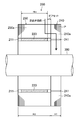
- FIG. 1 is a cross-sectional view of a motor according to Embodiment 1 of the present invention.
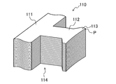
- FIG. 2 is a perspective view of the stator according to the first embodiment.
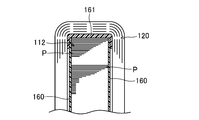
- FIG. 3 is a cross-sectional view of the tooth portion of the stator core according to the first embodiment when viewed from the inner peripheral side.
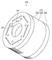
- FIG. 4 is a perspective view of the rotor according to the first embodiment.
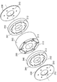
- FIG. 5 is a cross-sectional view of the rotor according to the first embodiment.
- FIG. 6 is a plan view of the first rotor core as seen from the axial direction.
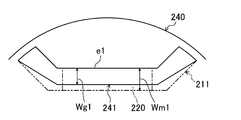
- FIG. 7 is a diagram for explaining the relationship between the position and size of the magnet slot and the air gap.
- FIG. 8 is a perspective view illustrating an assembled state of the rotor according to the first embodiment.
- FIG. 9 is a diagram illustrating a magnetic path (reverse magnetic field magnetic path) when a reverse magnetic field acts.
- FIG. 10 is a cross-sectional view of a rotor according to Embodiment 2 of the present invention.
- FIG. 11 is a cross-sectional view of a rotor according to Embodiment 3 of the present invention.
- FIG. 12 is a cross-sectional view of a rotor according to Embodiment 4 of the present invention.
- FIG. 13 is a cross-sectional view of a rotor according to Embodiment 5 of the present invention.
- FIG. 14 is a plan view of a rotor according to the sixth embodiment.
- FIG. 10 is a cross-sectional view of a rotor according to Embodiment 2 of the present invention.
- FIG. 11 is a cross-sectional view of a rotor according to Embodiment 3 of the present invention.
- FIG. 12 is a cross-sectional view of a
- FIG. 15 is a cross-sectional view of a rotor according to Embodiment 6 of the present invention.
- FIG. 16 is a plan view showing Modification 1 of the air gap.
- FIG. 17 is a plan view showing Modification Example 2 of the air gap.
- FIG. 18 is a plan view showing a third modification of the air gap.
- FIG. 19 is a plan view showing Variation 4 of the gap.
- FIG. 20 is a plan view showing a fifth modification of the air gap.
- FIG. 1 is a cross-sectional view of a motor (10) according to Embodiment 1 of the present invention.
- This motor (10) is used for, for example, an electric compressor (not shown) of an air conditioner.
- the motor (10) includes a stator (100), a rotor (200), and a drive shaft (300), and is accommodated in the casing (20) of the electric compressor.
- the axial direction refers to the direction of the axis of the drive shaft (300)
- the radial direction refers to the direction orthogonal to the axis.
- the outer peripheral side means a side farther from the axis
- the inner peripheral side means a side closer to the axis.
- the stator (100) includes a cylindrical stator core (110) and a coil (120).
- the stator core (110) is a laminated core obtained by punching an electromagnetic steel plate (P) by press working to create a laminated plate and laminating a plurality of laminated plates in the axial direction.
- FIG. 2 is a perspective view of the stator (100) of the first embodiment. As shown in FIGS. 1 and 2, the stator core (110) includes one back yoke portion (111), a plurality of (in this example, nine) teeth portions (112), and a flange portion (113). . In FIG. 2, one tooth portion (112) is mainly drawn.
- Each tooth portion (112) is a rectangular parallelepiped portion extending in the radial direction in the stator core (110) as shown in FIGS.
- a space between the teeth portions (112) is a slot (114) in which the coil (120) is accommodated.
- the back yoke part (111) has an annular shape.
- the back yoke portion (111) connects the teeth portions (112) on the outer peripheral side of the teeth portion (112).
- the outer peripheral portion of the back yoke portion (111) is fixed to the inner surface of the casing (20).
- the brim portion (113) is a portion connected to the inner peripheral side of each tooth portion (112).
- the brim portion (113) has a larger width (length in the circumferential direction) than the teeth portion (112).
- the collar portion (113) has a cylindrical inner surface. The cylindrical surface is opposed to an outer peripheral surface (cylindrical surface) of a rotor core (210) described later with a predetermined distance (air gap (G)).
- FIG. 3 is a cross-sectional view of the tooth portion (112) when the stator core (110) of the present embodiment is viewed from the inner peripheral side.
- an insulator (161) is provided from both axial end surfaces of the tooth portion (112), and an insulating film (160) is provided between the coil (120) and the tooth portion (112). Is provided.
- the insulating film (160) is a polyethylene terephthalate film.
- FIG. 4 is a perspective view of the rotor (200) of the first embodiment.
- FIG. 5 is a cross-sectional view of the rotor (200) of the first embodiment.
- the rotor (200) includes a rotor core (210) (magnetic core), a plurality of permanent magnets (220), and two end plates (230), and has a cylindrical shape.
- the rotor (200) includes six permanent magnets (220).
- the end plate (230) is not shown.
- the rotor core (210) is a laminated core obtained by punching an electromagnetic steel plate (P) by press working to create a laminated plate and laminating a plurality of laminated plates in the axial direction.
- the rotor core (210) is divided into an odd number (three in this example) of rotor cores in contact with each other in the axial direction. More specifically, the rotor core (210) is divided into two first rotor cores (240) arranged oddly from the axial end of the rotor core (210) and second rotor cores (250) arranged evenly. And is divided into three in the axial direction (see FIG. 5). As shown in FIG. 5, in this example, the height (H1) (the size in the axial direction) of the first rotor core (240) is smaller than the height (H2) of the second rotor core (250).
- first and second rotor cores (240, 250) and the like will be described in detail.
- first rotor core (240) and the second rotor core (250) are also referred to as divided rotor cores (240, 250).
- the second rotor core (250) is formed with a plurality of magnet slots (211) into which the permanent magnets (220) are respectively attached.
- Each of the magnet slots (211) is disposed at a 60 ° pitch around the axis of the second rotor core (250).
- Each magnet slot (211) has a substantially U-shape when viewed in the axial direction, and penetrates the second rotor core (250) in the axial direction.
- each magnet slot (211) includes a magnet insertion part (211a) orthogonal to the radius of the rotor core (210), and 2 extending outward from the magnet insertion part (211a).
- the magnet insertion portion (211a) is rectangular in plan view in FIG. 1, and the permanent magnet (220) is inserted into the magnet insertion portion (211a).
- the permanent magnet (220) is configured such that the axial height (Hm) is smaller than the axial height (H2) of the second rotor core (250) (see FIG. 5).
- FIG. 6 is a plan view of the first rotor core (240) viewed from the axial direction.
- the first rotor core (240) is provided with six gaps (241) penetrating in the axial direction. These gaps (241) are arranged to face the magnet slots (211) when the first rotor core (240) and the second rotor core (250) are overlapped.
- the magnet slots (211) corresponding to the respective gaps (241) are indicated by alternate long and short dash lines.
- FIG. 7 is a diagram for explaining the relationship between the position and size of the magnet slot (211) and the gap (241).
- the solid line indicates the shape of the gap (241)
- the alternate long and short dash line indicates the shape of the magnet slot (211).
- the gap (241) is rectangular in plan view in FIG.
- the width (Wg2) in the direction perpendicular to the radius in the gap (241) extends to the vicinity of the outer periphery of the first rotor core (240). By doing so, leakage magnetic flux generated between adjacent magnetic poles can be reduced.
- the air gap (241) has a smaller magnetic resistance than the magnet slot (211).
- the gap (241) has a radial width (Wg1) smaller than the radial width (Wm1) of the magnet insertion portion (211a).
- the radial direction position of the gap (241) is such that the long side (e1) on the outer peripheral side is on the inner peripheral side with respect to the long side (e2) of the magnet insertion part (211a).
- the width (Wg1) in the radial direction of the air gap (241) is formed to be larger than the air gap (G). This is because if the width (Wg1) is smaller than the air gap (G), the first rotor core (240) may cause a short circuit of magnetic flux.
- the end plate (230) has a disc shape and is formed of a nonmagnetic metal such as stainless steel.
- the end plate (230) and the first and second rotor cores (240, 250) are each formed with six bolt holes (213) that pass through in the axial direction and overlap each other when they are stacked.
- FIG. 8 is a perspective view illustrating an assembled state of the rotor (200) of the present embodiment.
- the permanent magnet (220) is attached to the magnet insertion part (211a).
- each permanent magnet (220) has its both ends in the axial direction offset inward from the axial end of the second rotor core (250).
- the permanent magnet (220) is fixed to the second rotor core (250) by, for example, bonding so as not to move in the magnet insertion portion (211a).
- the first and second rotor cores (240, 250) are arranged with the first rotor core (240) being odd-numbered from one end, and the second rotor core (250) being even-numbered from the one end.
- the second rotor core (250) is sandwiched between the first rotor core (240) from both axial ends.
- the first and third from the end of the rotor (200) are the first rotor core (240), and the second is the second rotor core (250).
- the positional relationship between the first rotor core (240) and the second rotor core (250) is matched so that each magnet slot (211) and the gap (241) of the first rotor core (240) overlap ( (See FIGS. 6 and 7).
- the first rotor core (240) and the second rotor core (250) are in contact with each other by overlapping the first rotor core (240) and the second rotor core (250), but the axial ends of the respective permanent magnets (220).
- the portion is offset inward from the axial end of the second rotor core (250), the permanent magnet (220) does not contact the first rotor core (240).
- end plates (230) are attached from the end of each first rotor core (240).
- the end plate (230) and the rotor core (210) are fixed by six bolts (270) (see FIG. 1) passed through the bolt holes (213).
- a shaft hole (212) is formed at the center of the first and second rotor cores (240, 250).
- a drive shaft (300) made of metal such as iron is shrink-fitted into the shaft hole (212).
- the drive shaft (300) is for driving a compression mechanism (not shown) in the electric compressor.
- FIG. 9 is a diagram illustrating a magnetic path (reverse magnetic field magnetic path) when a reverse magnetic field acts.
- a reverse magnetic field acts on the rotor (200) of the present embodiment
- a magnetic flux acts on the magnetic core portions (240a, 250a) (see FIG. 5) on the outer peripheral side of the permanent magnet (220) from the stator (100).
- This magnetic flux is directed to the magnetic core portion (250a) on the permanent magnet (220) side to some extent, but most of the magnetic flux is directed to the magnetic core portion (240a) of each first rotor core (240) as indicated by an arrow in FIG. Head to.
- the magnetic resistance of the air gap (241) of the first rotor core (240) is smaller than the magnetic resistance of the magnet slot (211). That is, in the motor (10) of this embodiment, the strength of the reverse magnetic field acting on the permanent magnet (220) is smaller than that of the conventional motor. Therefore, in this embodiment, it becomes possible to take measures against demagnetization of the permanent magnet (220) due to a reverse magnetic field.
- the motor (10) can generate reluctance torque by the first rotor core (240). That is, in this embodiment, the decrease in magnet torque can be compensated by the reluctance torque in the first rotor core (240).
- each magnet slot (211) is covered by the first rotor core (240). Therefore, it is possible to omit a cover or the like that prevents the permanent magnet (220) from coming off.
- FIG. 10 is a cross-sectional view of a rotor (200) according to Embodiment 2 of the present invention.
- the rotor (200) of the present embodiment includes one first rotor core (240) and one second rotor core (250). Also in this example, the height (H1) of the first rotor core (240) (the axial size) is smaller than the height (H2) of the second rotor core (250). Further, the first rotor core (240) and the second rotor core (250) are in contact with each other at the axial ends.
- the second rotor core (250) can easily insert the permanent magnet (220) into the magnet slot (211) from the axial end portion side not in contact with the first rotor core (240). Further, in the second rotor core (250), a cover or the like for preventing the permanent magnet (220) from coming off is not required on the axial end portion side in contact with the first rotor core (240).
- FIG. 11 is a cross-sectional view of a rotor (200) according to Embodiment 3 of the present invention.
- the rotor (200) of the present embodiment includes one first rotor core (240) and two second rotor cores (250).
- the first rotor core (240) is connected to the second rotor core (250 from both axial ends thereof. ).
- the height (H1) of the first rotor core (240) (the axial size) is smaller than the height (H2) of the second rotor core (250).
- the permanent magnet (220) can be inserted from both axial ends of the rotor (200). Therefore, assembly of the rotor (200) is facilitated.
- FIG. 12 is a cross-sectional view of a rotor (200) according to Embodiment 4 of the present invention.
- the rotor (200) includes two first rotor cores (240) and two second rotor cores (250), and the first and second rotor cores (240, 250) are alternately stacked.
- the height (H1) of the first rotor core (240) (the axial size) is smaller than the height (H2) of the second rotor core (250).
- FIG. 13 is a cross-sectional view of a rotor (200) according to Embodiment 5 of the present invention.
- the rotor (200) includes three first rotor cores (240) and two second rotor cores (250).
- the first rotor core (240) and the second rotor core (250) are alternately stacked.
- the height (H1) of the first rotor core (240) (the axial size) is smaller than the height (H2) of the second rotor core (250).
- H1 of the first rotor core (240) the axial size
- H2 height
- FIG. 14 is a plan view of the rotor (200) according to the sixth embodiment.
- FIG. 15 is a cross-sectional view of a rotor (200) according to Embodiment 6 of the present invention.
- FIG. 15 corresponds to the AA cross section of FIG.
- the rotor (200) of the present embodiment includes one first rotor core (240) and two second rotor cores (250), and the first rotor core (240) has both axial ends. And sandwiched between the second rotor cores (250). Also in this example, the height (H1) of the first rotor core (240) (the axial size) is smaller than the height (H2) of the second rotor core (250).
- the permanent magnet (220) is provided so as to constitute a multilayer for each pole. Specifically, three layers of permanent magnets (220) are provided on each pole.
- the permanent magnet (220) on the outermost peripheral side of the rotor (200) is provided only in the second rotor core (250). Further, the second and third permanent magnets (220) from the outer peripheral side of the rotor (200) are provided so as to penetrate the first and second rotor cores (240, 250).
- the second rotor core (250) is provided with a multilayer magnet slot (211) for each pole.
- the air gap (241) is provided only at a position corresponding to the outermost permanent magnet (220).
- each 1st rotor core (240) is the position of a 2nd rotor core (250) instead of a space
- a magnet slot (211) connected to the magnet slot (211) is formed.
- the demagnetization of the permanent magnet (220) corresponding to the air gap (241) Measures can be taken.
- the first rotor core (240) and the second rotor core (250) are the same as those in the first, second, fourth, and fourth embodiments. 5 can be arranged.
- a layer closer to the inner periphery than the first layer may have a gap (241) as in the first layer.
- the shape of the gap (241) is not limited to the above example. In each embodiment, for example, a gap (241) having a form exemplified below can be adopted.
- FIG. 16 is a plan view showing Modification 1 of the gap (241).
- the air gap (241) illustrated in FIG. 16 is a through-hole having a cross-sectional shape (projected shape in the axial direction) along the magnet slot (211) and narrower than the magnet slot (211). Also in this example, the end (241a) of the gap (241) extends to the vicinity of the outer periphery of the first rotor core (240).
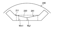
- FIG. 17 is a plan view showing Modification 2 of the gap (241).
- the projected shape of the gap (241) in the axial direction is such that the radial width (Wg1) is the radial width (Wm1) of the magnet insertion portion (211a) at the portion overlapping the magnet insertion portion (211a).
- the long side (e1) on the outer peripheral side of the gap (241) is in a position overlapping the long side (e2) of the magnet insertion part (211a), but the long sides on the inner peripheral side overlap each other.
- the positional relationship between the air gap (241) and the magnet slot (211) may be determined.
- FIG. 18 is a plan view showing Modification 3 of the gap (241).
- the projected shape of the gap (241) in the axial direction is such that the width (Wg3) is narrower than the width of the barrier portion (211b) at the portion overlapping the barrier portion (211b), and the magnet insertion portion ( The portion overlapping 211a) is the same as or larger than the width (Wm1) of the magnet insertion portion (211a).
- FIG. 18 shows an example in which the width (Wg1) is larger than the width (Wm1).
- FIG. 19 is a plan view showing Modification 4 of the gap (241).
- the projected shape of the gap (241) in the axial direction is recessed near the center in the portion overlapping the magnet insertion portion (211a). Therefore, the radial width (Wg1) of the gap (241) is smaller than the radial width (Wm1) of the magnet slot (211).
- the portion that overlaps the barrier portion (211b) is generally shaped to overlap the barrier portion (211b).
- FIG. 20 is a plan view showing Modification 5 of the gap (241).
- the projected shape of the gap (241) in the axial direction is such that the inner peripheral line near both ends of the magnet insertion portion (211a) is recessed toward the outer peripheral side.
- the gap (241) has a width (Wg4) near the end of the magnet insertion portion (211a) smaller than a width near the center of the magnet slot (211).
- the inner circumferential side line of the gap (241) is dented toward the outer circumferential side, but the outer circumferential side line may be dented toward the inner circumferential side or dented from both the inner and outer sides. Good.
- the end of the air gap (241) in the direction perpendicular to the radius (the end (241a) or the like) extends as close as possible to the outer periphery of the first rotor core (240). This is because it is advantageous for reducing the leakage magnetic flux between adjacent poles.
- any of the air gaps (241) described in the above embodiments and modifications may be shifted within a range overlapping the projection surface in the axial direction of the permanent magnet (220). Further, as shown in FIG. 16 and the like, the air gap (241) does not have to be line symmetric with the radius as the axis of symmetry. You may combine the form of the space
- the number of divisions of the rotor core (210), that is, the number of the first and second rotor cores (240, 250) is an example.
- first and second rotor cores (240, 250) are not limited to laminated cores (electromagnetic steel plates).
- the first and second rotor cores (240, 250) can be made of a dust magnetic material.
- the rotor (200) is configured by combining the cores made of different kinds of magnetic materials, such as the first rotor core (240) made of powder magnetic material and the second rotor core (250) made of electromagnetic steel plate. May be.
- the end plate (230) may be omitted.
- the end plate (230) for preventing the magnet from coming off is made of a non-magnetic material or a magnetic material.
- the material cost increases, and in the case of a magnetic material, leakage of magnetic flux occurs.
- omitting the end plate (230) has the effect of reducing costs or improving torque.
- the present invention can be applied to a generator in addition to a motor.
- the present invention can also be applied to a rotating electric machine in which a coil is distributedly wound around a stator core.
- the present invention is useful as a rotor having a rotor core on which a magnet is mounted, and a rotating electric machine using the rotor.
Landscapes
- Engineering & Computer Science (AREA)
- Power Engineering (AREA)
- Permanent Field Magnets Of Synchronous Machinery (AREA)
- Iron Core Of Rotating Electric Machines (AREA)
- Permanent Magnet Type Synchronous Machine (AREA)
Abstract
La présente invention porte sur un mécanisme électrique tournant qui comprend un rotor ayant des noyaux de rotor sur lesquels des aimants ont été montés, dans lequel la démagnétisation des aimants peut être contrecarrée en même temps que la détérioration de la performance du mécanisme électrique tournant est évitée. Ce rotor comprend : des premiers noyaux de rotor (240) comprenant une pluralité d'espaces (241) qui le traversent dans la direction axiale ; et un second noyau (250) en contact avec les extrémités axiales des premiers noyaux de rotor (240), le second noyau présentant une pluralité d'encoches d'aimants (211) dans des positions qui font face aux espaces (241). Les espaces (241) sont formés avec une résistance magnétique inférieure à celle des encoches d'aimants (211). Cette configuration apporte la possibilité de réduire l'intensité du champ magnétique inverse qui agit sur les aimants permanents (220) et d'obtenir qu'un couple de réluctance soit produit par les premiers noyaux de rotor (240). De cette façon, la démagnétisation des aimants peut être contrecarrée tandis qu'une détérioration de la performance peut être évitée dans un mécanisme électrique tournant qui comprend un rotor ayant des noyaux de rotor sur lesquels des aimants ont été montés.
Priority Applications (4)
| Application Number | Priority Date | Filing Date | Title |
|---|---|---|---|
| US14/008,386 US9712006B2 (en) | 2011-03-31 | 2012-03-21 | Rotor and rotary electric machine using the same |
| CN201280013249.5A CN103430430B (zh) | 2011-03-31 | 2012-03-21 | 转子及使用该转子的旋转电气机械 |
| EP12763654.6A EP2693605B1 (fr) | 2011-03-31 | 2012-03-21 | Rotor et mécanisme électrique tournant utilisant ce rotor |
| ES12763654.6T ES2635600T3 (es) | 2011-03-31 | 2012-03-21 | Rotor y máquina eléctrica rotatoria que usa el mismo |
Applications Claiming Priority (2)
| Application Number | Priority Date | Filing Date | Title |
|---|---|---|---|
| JP2011-077880 | 2011-03-31 | ||
| JP2011077880 | 2011-03-31 |
Publications (1)
| Publication Number | Publication Date |
|---|---|
| WO2012132331A1 true WO2012132331A1 (fr) | 2012-10-04 |
Family
ID=46930116
Family Applications (1)
| Application Number | Title | Priority Date | Filing Date |
|---|---|---|---|
| PCT/JP2012/001949 Ceased WO2012132331A1 (fr) | 2011-03-31 | 2012-03-21 | Rotor et mécanisme électrique tournant utilisant ce rotor |
Country Status (6)
| Country | Link |
|---|---|
| US (1) | US9712006B2 (fr) |
| EP (1) | EP2693605B1 (fr) |
| JP (1) | JP5234202B2 (fr) |
| CN (1) | CN103430430B (fr) |
| ES (1) | ES2635600T3 (fr) |
| WO (1) | WO2012132331A1 (fr) |
Cited By (3)
| Publication number | Priority date | Publication date | Assignee | Title |
|---|---|---|---|---|
| US20150280500A1 (en) * | 2012-11-01 | 2015-10-01 | Mitsubishi Electric Corporation | Permanent magnet embedded motor, compressor, and refrigeration and air conditioning device |
| JP2019517768A (ja) * | 2016-06-07 | 2019-06-24 | シーメンス アクチエンゲゼルシヤフトSiemens Aktiengesellschaft | リラクタンス機のための回転子 |
| WO2019175927A1 (fr) * | 2018-03-12 | 2019-09-19 | 三菱電機株式会社 | Moteur électrique, compresseur, soufflante et dispositif de réfrigération et de climatisation |
Families Citing this family (22)
| Publication number | Priority date | Publication date | Assignee | Title |
|---|---|---|---|---|
| US10481211B2 (en) * | 2014-01-15 | 2019-11-19 | Lat Enterprises, Inc. | State-of-charge indicator |
| JP2015154665A (ja) * | 2014-02-18 | 2015-08-24 | 株式会社ジェイテクト | ロータ及びロータの製造方法 |
| AU2016390095B9 (en) * | 2016-01-27 | 2018-12-13 | Mitsubishi Electric Corporation | Magnetizing method, rotor, electric motor, and scroll compressor |
| DE112016006315T5 (de) * | 2016-01-27 | 2018-10-18 | Mitsubishi Electric Corporation | Rotor, Magnetisierungsverfahren, Motor und Scrollverdichter |
| CN106253615B (zh) * | 2016-08-26 | 2019-01-08 | 广东威灵电机制造有限公司 | 电机 |
| KR101961142B1 (ko) * | 2017-01-02 | 2019-03-25 | 엘지전자 주식회사 | 전동기 및 그의 로터의 제조방법 |
| JP6627784B2 (ja) * | 2017-01-11 | 2020-01-08 | トヨタ自動車株式会社 | 回転電機ロータ |
| EP3490112A4 (fr) * | 2017-06-05 | 2020-02-19 | Top Co., Ltd. | Rotor et machine rotative |
| IT201700100814A1 (it) * | 2017-09-08 | 2019-03-08 | S M E S P A | Procedimento per l'assemblaggio di un rotore di un motore sincrono a riluttanza variabile e tale rotore |
| JP2019161698A (ja) * | 2018-03-07 | 2019-09-19 | 本田技研工業株式会社 | 回転電機のロータ組立体及び回転電機 |
| WO2019242218A1 (fr) * | 2018-06-20 | 2019-12-26 | 广东美芝制冷设备有限公司 | Rotor, moteur et compresseur |
| CN108768015B (zh) * | 2018-07-20 | 2020-04-17 | 珠海格力电器股份有限公司 | 转子组件及电机 |
| CN110875659A (zh) * | 2018-08-30 | 2020-03-10 | 广东美芝制冷设备有限公司 | 旋转电机转子、电机及压缩机 |
| US11949291B2 (en) | 2019-02-22 | 2024-04-02 | Mitsubishi Electric Corporation | Motor having rotor with different core regions, compressor, and air conditioner having the motor |
| WO2020201937A1 (fr) * | 2019-03-29 | 2020-10-08 | The Trustees For The Time Being Of The Kmn Fulfilment Trust | Machine électrique dotée d'un élément de rotor comprenant de la magnétite |
| EP3780350B1 (fr) * | 2019-08-14 | 2022-07-13 | Secop GmbH | Rotor à aimant permanent intérieur pour un compresseur de réfrigérant |
| DE102019129243A1 (de) * | 2019-10-30 | 2021-05-06 | Valeo Siemens Eautomotive Germany Gmbh | Rotor für eine elektrische Maschine, zugehöriges Herstellungsverfahren und elektrische Maschine zum Antreiben eines Fahrzeugs |
| US20230208223A1 (en) * | 2020-06-25 | 2023-06-29 | Mitsubishi Electric Corporation | Motor, compressor, and refrigeration cycle apparatus |
| CN112436689B (zh) * | 2020-12-18 | 2022-09-13 | 山东理工大学 | 自带止退功能的嵌套式驱动电机凸极转子生产方法 |
| CN219181380U (zh) | 2022-12-14 | 2023-06-13 | 日本电产株式会社 | 同步磁阻电机 |
| US20250119009A1 (en) * | 2023-10-09 | 2025-04-10 | GM Global Technology Operations LLC | Rotor for electric machine |
| US12573927B2 (en) * | 2023-10-10 | 2026-03-10 | GM Global Technology Operations LLC | Hybrid rotor for synchronous machine |
Citations (4)
| Publication number | Priority date | Publication date | Assignee | Title |
|---|---|---|---|---|
| JPH0851751A (ja) | 1994-08-10 | 1996-02-20 | Toshiba Corp | 永久磁石式回転電機 |
| JP2002354729A (ja) * | 2001-05-25 | 2002-12-06 | Hitachi Ltd | 永久磁石式回転電機およびそれを用いた空気調和機 |
| JP2002354730A (ja) * | 2001-05-25 | 2002-12-06 | Hitachi Ltd | 永久磁石式回転電機 |
| JP2004088852A (ja) * | 2002-08-23 | 2004-03-18 | Daikin Ind Ltd | 電動機およびそれを用いた圧縮機 |
Family Cites Families (8)
| Publication number | Priority date | Publication date | Assignee | Title |
|---|---|---|---|---|
| US5808392A (en) | 1994-04-28 | 1998-09-15 | Kabushiki Kaisha Toshiba | Permanent magnet type rotating machine |
| CN2264439Y (zh) * | 1996-05-06 | 1997-10-08 | 韩泰勋 | 轴向串相式交流低速同步电动机 |
| JPH1189145A (ja) * | 1997-09-10 | 1999-03-30 | Fujitsu General Ltd | 永久磁石形モータ |
| CN1210860C (zh) * | 1999-07-16 | 2005-07-13 | 松下电器产业株式会社 | 永久磁铁同步电动机 |
| JP2006014473A (ja) * | 2004-06-25 | 2006-01-12 | Aisin Seiki Co Ltd | モータ |
| JP5130679B2 (ja) * | 2006-09-07 | 2013-01-30 | 株式会社明電舎 | 順突極モータ |
| DE102006056873A1 (de) * | 2006-12-01 | 2008-06-05 | Siemens Ag | Permanentmagnetrotor mit Aufbiegungen zum Fixieren der Permanentmagnete des Rotorpaketes |
| EP2676356A1 (fr) * | 2011-02-17 | 2013-12-25 | CERN - European Organization For Nuclear Research | Système et procédé permettant de positionner et de fixer un certain nombre d'objets les uns par rapport aux autres |
-
2012
- 2012-03-21 WO PCT/JP2012/001949 patent/WO2012132331A1/fr not_active Ceased
- 2012-03-21 JP JP2012063266A patent/JP5234202B2/ja active Active
- 2012-03-21 EP EP12763654.6A patent/EP2693605B1/fr active Active
- 2012-03-21 ES ES12763654.6T patent/ES2635600T3/es active Active
- 2012-03-21 CN CN201280013249.5A patent/CN103430430B/zh active Active
- 2012-03-21 US US14/008,386 patent/US9712006B2/en active Active
Patent Citations (4)
| Publication number | Priority date | Publication date | Assignee | Title |
|---|---|---|---|---|
| JPH0851751A (ja) | 1994-08-10 | 1996-02-20 | Toshiba Corp | 永久磁石式回転電機 |
| JP2002354729A (ja) * | 2001-05-25 | 2002-12-06 | Hitachi Ltd | 永久磁石式回転電機およびそれを用いた空気調和機 |
| JP2002354730A (ja) * | 2001-05-25 | 2002-12-06 | Hitachi Ltd | 永久磁石式回転電機 |
| JP2004088852A (ja) * | 2002-08-23 | 2004-03-18 | Daikin Ind Ltd | 電動機およびそれを用いた圧縮機 |
Cited By (12)
| Publication number | Priority date | Publication date | Assignee | Title |
|---|---|---|---|---|
| US20150280500A1 (en) * | 2012-11-01 | 2015-10-01 | Mitsubishi Electric Corporation | Permanent magnet embedded motor, compressor, and refrigeration and air conditioning device |
| EP2916434A4 (fr) * | 2012-11-01 | 2016-06-29 | Mitsubishi Electric Corp | Moteur électrique avec aimant permanent encastré, compresseur et équipement de réfrigération et de climatisation |
| US9800105B2 (en) * | 2012-11-01 | 2017-10-24 | Mitsubishi Electric Corporation | Permanent magnet embedded motor, compressor, and refrigeration and air conditioning device |
| JP2019517768A (ja) * | 2016-06-07 | 2019-06-24 | シーメンス アクチエンゲゼルシヤフトSiemens Aktiengesellschaft | リラクタンス機のための回転子 |
| WO2019175927A1 (fr) * | 2018-03-12 | 2019-09-19 | 三菱電機株式会社 | Moteur électrique, compresseur, soufflante et dispositif de réfrigération et de climatisation |
| KR20200098643A (ko) * | 2018-03-12 | 2020-08-20 | 미쓰비시덴키 가부시키가이샤 | 전동기, 압축기, 송풍기, 및 냉동 공조 장치 |
| JPWO2019175927A1 (ja) * | 2018-03-12 | 2020-10-01 | 三菱電機株式会社 | 電動機、圧縮機、送風機、及び冷凍空調装置 |
| JP2022051837A (ja) * | 2018-03-12 | 2022-04-01 | 三菱電機株式会社 | 電動機、圧縮機、送風機、及び冷凍空調装置 |
| US11394258B2 (en) | 2018-03-12 | 2022-07-19 | Mitsubishi Electric Corporation | Electric motor, compressor, fan, and refrigerating and air conditioning apparatus |
| KR102459101B1 (ko) | 2018-03-12 | 2022-10-26 | 미쓰비시덴키 가부시키가이샤 | 전동기, 압축기, 송풍기, 및 냉동 공조 장치 |
| JP7194165B2 (ja) | 2018-03-12 | 2022-12-21 | 三菱電機株式会社 | 電動機、圧縮機、送風機、及び冷凍空調装置 |
| JP7362801B2 (ja) | 2018-03-12 | 2023-10-17 | 三菱電機株式会社 | 電動機、圧縮機、送風機、及び冷凍空調装置 |
Also Published As
| Publication number | Publication date |
|---|---|
| US9712006B2 (en) | 2017-07-18 |
| ES2635600T3 (es) | 2017-10-04 |
| JP5234202B2 (ja) | 2013-07-10 |
| US20140021820A1 (en) | 2014-01-23 |
| CN103430430B (zh) | 2016-08-17 |
| EP2693605A1 (fr) | 2014-02-05 |
| EP2693605A4 (fr) | 2016-03-23 |
| CN103430430A (zh) | 2013-12-04 |
| JP2013034362A (ja) | 2013-02-14 |
| EP2693605B1 (fr) | 2017-07-19 |
Similar Documents
| Publication | Publication Date | Title |
|---|---|---|
| JP5234202B2 (ja) | ロータ及びそれを用いた回転電気機械 | |
| JP5933743B2 (ja) | 永久磁石埋込型電動機、圧縮機、および冷凍空調装置 | |
| JP4169055B2 (ja) | 回転電機 | |
| JP6512060B2 (ja) | 回転電機のロータ | |
| JP2012213268A (ja) | 回転電気機械 | |
| CN101855808A (zh) | 旋转电机的转子 | |
| JP5656719B2 (ja) | 永久磁石型回転電機及び永久磁石型回転電機の製造方法 | |
| US20150061443A1 (en) | Rotor and rotary electric machine having the same | |
| CN103683596A (zh) | 永磁旋转电机 | |
| WO2015098159A1 (fr) | Moteur d'induction magnétique et son procédé de fabrication | |
| WO2017195498A1 (fr) | Rotor et machine électrique rotative | |
| WO2014175009A1 (fr) | Moteur électrique à aimant permanent | |
| JP2013236418A (ja) | 回転電気機械 | |
| JP5702118B2 (ja) | ロータの構造及びモータ | |
| WO2022114176A1 (fr) | Moteur électrique | |
| JP5041415B2 (ja) | アキシャルギャップ型モータ | |
| WO2016203530A1 (fr) | Moteur intégré à aimant permanent et compresseur | |
| CN113541348A (zh) | 旋转电机 | |
| JP5122124B2 (ja) | アキシャルギャップ型回転機、及びこれを搭載した空調用圧縮機、送風機、及び自動車 | |
| JP2012244808A (ja) | 回転電機のロータ | |
| JP5720375B2 (ja) | 回転電気機械 | |
| JP5729090B2 (ja) | ロータ及び回転電気機械 | |
| JP2009038897A (ja) | アキシャルギャップ型モータ | |
| JP2013179765A (ja) | 回転電気機械 | |
| JP2015006110A (ja) | モータ装置 |
Legal Events
| Date | Code | Title | Description |
|---|---|---|---|
| 121 | Ep: the epo has been informed by wipo that ep was designated in this application |
Ref document number: 12763654 Country of ref document: EP Kind code of ref document: A1 |
|
| WWE | Wipo information: entry into national phase |
Ref document number: 14008386 Country of ref document: US |
|
| NENP | Non-entry into the national phase |
Ref country code: DE |
|
| REEP | Request for entry into the european phase |
Ref document number: 2012763654 Country of ref document: EP |
|
| WWE | Wipo information: entry into national phase |
Ref document number: 2012763654 Country of ref document: EP |