WO2012132450A1 - Capteur de pression interne de cylindre pour moteur - Google Patents
Capteur de pression interne de cylindre pour moteur Download PDFInfo
- Publication number
- WO2012132450A1 WO2012132450A1 PCT/JP2012/002182 JP2012002182W WO2012132450A1 WO 2012132450 A1 WO2012132450 A1 WO 2012132450A1 JP 2012002182 W JP2012002182 W JP 2012002182W WO 2012132450 A1 WO2012132450 A1 WO 2012132450A1
- Authority
- WO
- WIPO (PCT)
- Prior art keywords
- pressure
- internal pressure
- ring block
- pressure sensor
- engine
- Prior art date
- Legal status (The legal status is an assumption and is not a legal conclusion. Google has not performed a legal analysis and makes no representation as to the accuracy of the status listed.)
- Ceased
Links
Images







Classifications
-
- F—MECHANICAL ENGINEERING; LIGHTING; HEATING; WEAPONS; BLASTING
- F02—COMBUSTION ENGINES; HOT-GAS OR COMBUSTION-PRODUCT ENGINE PLANTS
- F02F—CYLINDERS, PISTONS OR CASINGS, FOR COMBUSTION ENGINES; ARRANGEMENTS OF SEALINGS IN COMBUSTION ENGINES
- F02F1/00—Cylinders; Cylinder heads
-
- F—MECHANICAL ENGINEERING; LIGHTING; HEATING; WEAPONS; BLASTING
- F02—COMBUSTION ENGINES; HOT-GAS OR COMBUSTION-PRODUCT ENGINE PLANTS
- F02D—CONTROLLING COMBUSTION ENGINES
- F02D35/00—Controlling engines, dependent on conditions exterior or interior to engines, not otherwise provided for
- F02D35/02—Controlling engines, dependent on conditions exterior or interior to engines, not otherwise provided for on interior conditions
- F02D35/023—Controlling engines, dependent on conditions exterior or interior to engines, not otherwise provided for on interior conditions by determining the cylinder pressure
-
- G—PHYSICS
- G01—MEASURING; TESTING
- G01L—MEASURING FORCE, STRESS, TORQUE, WORK, MECHANICAL POWER, MECHANICAL EFFICIENCY, OR FLUID PRESSURE
- G01L23/00—Devices or apparatus for measuring or indicating or recording rapid changes, such as oscillations, in the pressure of steam, gas, or liquid; Indicators for determining work or energy of steam, internal-combustion, or other fluid-pressure engines from the condition of the working fluid
- G01L23/08—Devices or apparatus for measuring or indicating or recording rapid changes, such as oscillations, in the pressure of steam, gas, or liquid; Indicators for determining work or energy of steam, internal-combustion, or other fluid-pressure engines from the condition of the working fluid operated electrically
- G01L23/10—Devices or apparatus for measuring or indicating or recording rapid changes, such as oscillations, in the pressure of steam, gas, or liquid; Indicators for determining work or energy of steam, internal-combustion, or other fluid-pressure engines from the condition of the working fluid operated electrically by pressure-sensitive members of the piezoelectric type
-
- G—PHYSICS
- G01—MEASURING; TESTING
- G01L—MEASURING FORCE, STRESS, TORQUE, WORK, MECHANICAL POWER, MECHANICAL EFFICIENCY, OR FLUID PRESSURE
- G01L23/00—Devices or apparatus for measuring or indicating or recording rapid changes, such as oscillations, in the pressure of steam, gas, or liquid; Indicators for determining work or energy of steam, internal-combustion, or other fluid-pressure engines from the condition of the working fluid
- G01L23/22—Devices or apparatus for measuring or indicating or recording rapid changes, such as oscillations, in the pressure of steam, gas, or liquid; Indicators for determining work or energy of steam, internal-combustion, or other fluid-pressure engines from the condition of the working fluid for detecting or indicating knocks in internal-combustion engines; Units comprising pressure-sensitive members combined with ignitors for firing internal-combustion engines
- G01L23/221—Devices or apparatus for measuring or indicating or recording rapid changes, such as oscillations, in the pressure of steam, gas, or liquid; Indicators for determining work or energy of steam, internal-combustion, or other fluid-pressure engines from the condition of the working fluid for detecting or indicating knocks in internal-combustion engines; Units comprising pressure-sensitive members combined with ignitors for firing internal-combustion engines for detecting or indicating knocks in internal combustion engines
- G01L23/222—Devices or apparatus for measuring or indicating or recording rapid changes, such as oscillations, in the pressure of steam, gas, or liquid; Indicators for determining work or energy of steam, internal-combustion, or other fluid-pressure engines from the condition of the working fluid for detecting or indicating knocks in internal-combustion engines; Units comprising pressure-sensitive members combined with ignitors for firing internal-combustion engines for detecting or indicating knocks in internal combustion engines using piezoelectric devices
Definitions
- the present invention relates to an engine cylinder internal pressure sensor configured in a ring shape suitable for use in detecting the internal pressure of a cylinder.
- an engine cylinder internal pressure sensor that detects an internal pressure (combustion pressure) of a cylinder by facing the combustion chamber of the engine.
- This type of cylinder internal pressure sensor is a through-hole formed at a predetermined position of a cylinder. It needs to be installed independently due to its high airtight structure. For this reason, the cylinder pressure sensor is configured in a ring shape, and can be mounted integrally on the outer peripheral surface of the tip of the spark plug, which is another functional part attached to the engine, and can be mounted on the cylinder together with the spark plug.
- Such a cylinder internal pressure sensor is also known.
- the combustion pressure sensor of Patent Document 1 is built in an ignition plug having an insulator formed around a center electrode, and a washer member electrically connected to the side electrode and formed around the insulator.
- the combustion pressure sensor is configured to include a piezoelectric element made of lithium niobate disposed between an insulator and a washer member and in the vicinity of an ignition gap between a center electrode and a side electrode.
- the pressure sensor disclosed in Patent Document 2 is a pressure sensor that is fastened together with a mounting hole instead of a gasket of a spark plug.
- the pressure sensor has a mounting surface of a housing pressed against a cylinder head, and the housing is radiated with heat. It has a configuration in which fins are fixed.
- the spark plug with a built-in pressure sensor disclosed in Patent Document 3 is installed in the seat portion facing the plug mounting surface provided in the internal combustion engine when installed in the internal combustion engine.
- the Ri, and a, and the lead member for taking out the output of the piezoelectric element is connected to an insulating plate provided on the upper surface of the electrode plate with the terminal of the electrode plate protruding upward from the notch, and a terminal protruding from the notch of the insulating plate.
- JP-A-4-34327 Japanese Patent Laid-Open No. 11-94675 JP 2000-277233 A
- the pressure detecting element used is made of a single crystal material having high heat resistance and good piezoelectric conversion characteristics even in a high temperature environment. desirable.
- the single crystal material is highly brittle, cutting a single crystal material and cutting out the ring-shaped pressure detection element as in Patent Documents 1 and 2 described above requires a high degree of processing technology. Manufacture is not easy. Eventually, the yield and mass productivity are reduced, and the cost increase cannot be ignored.
- it is necessary to form the whole in a thin ring shape there is a possibility that problems such as cracking may occur when it is attached to an engine with large vibrations, and it cannot necessarily be said to be a highly reliable pressure detection element.
- Patent Document 3 since the pressure detection element is formed as a rectangular parallelepiped chip body and a plurality of chip bodies are arranged in a ring shape, manufacturing (processing) in the case of integrally forming the ring shape described above. Although the above problems do not occur, on the other hand, variations in the dimensions and angles of each chip body directly affect the characteristics (performance) of the cylinder internal pressure sensor, which tends to cause a decrease in detection accuracy and product variations. .
- An object of the present invention is to provide an engine cylinder internal pressure sensor that solves the problems existing in the background art.
- the present invention has a ring shape that detects the internal pressure Pc of the cylinder Ec by being mounted on the outer peripheral surfaces Mas and Mbs of the front end portions of the functional parts Ma and Mb facing the combustion chamber Rb of the engine.
- a housing including an outer cylinder portion 2e and an inner cylinder portion 2i formed by forming elastic portions 2es and 2is having elasticity in the axial direction Fs at an intermediate portion Xm in the axial direction Fs.
- the unit 2 is hermetically fixed between the outer cylindrical portion 2e and the inner cylindrical portion 2i positioned in front of the elastic portions 2es and 2is, and is exposed to the rear of the elastic portions 2e and 2i through the elastic portions 2e and 2i.
- the pressure receiving ring block portion 3 whose front surface 3f is a pressure receiving surface and one electrode portion 4 provided on the rear surface 3r of the pressure receiving ring block portion 3 are in contact with the pressure receiving ring block portion.
- the internal pressure Pc is applied from the portion 3, and is fixed between at least one or more pressure detection elements 5a, 5b, 5c... Disposed at a predetermined position in the circumferential direction Ff, and the outer cylindrical portion 2e and the inner cylindrical portion 2i.
- the front surface 6f serves as a support surface for supporting the pressure detection elements 5a, and includes a support ring block portion 6 that also serves as the other electrode 7.
- one or more spacers 10a ..., 10as ... along the circumferential direction Ff are provided at portions other than the pressure detection elements 5a ... in contact with the rear surface portion of the pressure-receiving ring block portion 3. , 10 at is desirable.
- the pressure detection elements 5a and the spacers 10a,..., 10at are alternately arranged along the circumferential direction Ff of the pressure-receiving ring block portion 3, and the shafts of the spacers 10a,.
- the length in the direction Fs is selected according to the length in the axial direction Fs of the pressure detection elements 5a.
- the elastic portions 2es and 2is can be provided by forming bent portions (or curved portions) 11e and 11i in an intermediate portion Xm between the outer tube portion 2e and the inner tube portion 2i.
- the pressure receiving ring block portion 3 can be constituted by a pressure receiving ring main body portion 12 disposed on the front side, and an insulating block portion 13 which is disposed on the rear side so as to abut against the pressure receiving ring main body portion 12, and pressure detection.
- a single crystal material can be used for the elements 5a.
- the bonding layer C can be coated with the intermediate layer Cm serving as the diffusion preventing layer and the outer layer Ce serving as the diffusion layer.
- the rear surface 3r of the pressure-receiving ring block portion 3, the front surface 6f of the support ring block portion 6, the front surface 5af of the pressure detection elements 5a ... or the rear surface 5ar of the pressure detection elements 5a ... have a predetermined thickness Ls.
- An alignment adjustment layer 14 for the pressure detection elements 5a... Using the system bonding layer can be provided. Further, a connector portion 16 for connecting the lead 15 can be provided at a portion of the one electrode 4 where the pressure detecting elements 5a ... do not exist. At this time, the connector portion 16 has a space between the lead 15 and the one electrode 4. An intervening compressed spring 17 can be provided. Note that an injector Ma that injects fuel into the cylinder Ec or a spark plug Mb that ignites the fuel in the cylinder Ec can be applied to the functional components (Ma, Mb).
- the engine cylinder internal pressure sensor 1 according to the present invention has the following remarkable effects.
- a pressure receiving ring block part 3 Between the front side 2e and the inner cylinder part 2i, a pressure receiving ring block part 3, one electrode 4, at least one pressure detecting element 5a ... and a support ring block part 6 also serving as the other electrode 7 are arranged in order. Since it is configured, the pressure received by the pressure receiving ring block portion 3 can be stably (equally) and reliably transmitted to the pressure detecting elements 5a through the elastic portions 2es and 2is that expand and contract, and the pressure is highly accurate. Detection can be performed.
- At least one or more pressure detecting elements 5a that are in contact with one electrode portion 4 provided on the rear surface 3r of the pressure receiving ring block portion 3 whose front surface 3f serves as a pressure receiving surface and are arranged at equal intervals along the circumferential direction Ff.
- the pressure detection element 5a is made of a single crystal material having high brittleness and is attached to the outer peripheral surfaces Mas and Mbs of the front end portions of the functional parts Ma and Mb facing the combustion chamber Rb of the engine. Even when the cylinder internal pressure sensor 1 is configured, the manufacturing (processing) of the pressure detecting elements 5a... Is facilitated, the yield and mass productivity can be improved, and further, the cost can be reduced. It can also contribute to improved reliability.
- the cylindrical (ring-shaped) housing unit 2 covers the entire detection structure such as the pressure detection element 5a, the electrodes 4 and 7, and the severe temperature environment and vibration environment when detecting the combustion pressure of the engine. It effectively protects the entire detection structure, ensures stable mounting and stable operation with respect to the cylinder Ec, and can be easily mounted on various functional parts such as the injector Ma and spark plug Mb.
- the cylinder internal pressure sensor 1 can be obtained.
- one or more spacers 10a... 10as..., 10at along the circumferential direction Ff are provided on a portion excluding the pressure detection elements 5a. If arranged, the space between the pressure detection elements 5a can be filled with the spacers 10a ..., 10as ..., 10at, so that alignment adjustment of the pressure detection elements 5a ... during assembly is assisted and accurate alignment adjustment is possible. In addition, it can be performed easily and reliably and stably. In addition, it is possible to improve the mechanical strength and contribute to the cost reduction associated with the reduction in the number of pressure detection elements 5a.
- the elastic portions 2es and 2is are provided by forming the bent portions (or curved portions) 11e and 11i at the intermediate portion Xm between the outer tube portion 2e and the inner tube portion 2i according to a preferred embodiment, the outer tube portion Since it can be integrally formed by 2e and a part of the inner cylinder part 2i, it can be implemented in an easy and optimum form in manufacturing.
- an adhesion reinforcing layer is formed on the front surface 5af of the pressure detection element 5a, the rear surface 3r of the pressure receiving ring block portion 3, the rear surface 5ar of the pressure detection element 5a, and the front surface 6f of the support ring block portion 6. If the bonding layer C is coated with the inner layer Ci that becomes the diffusion layer, the intermediate layer Cm that becomes the diffusion prevention layer, and the outer layer Ce that becomes the diffusion layer, three parts of different materials, that is, the pressure receiving ring block portion 3, the pressure detection element 5a,. The support ring block portion 6 can be reliably bonded by the interposition of the bonding layers C.
- a predetermined thickness is applied to the rear surface 3r of the pressure-receiving ring block portion 3, the front surface 6f of the support ring block portion 6, the front surface 5af of the pressure detection element 5a, or the rear surface 5ar of the pressure detection element 5a.
- the alignment adjustment layer 14 for the pressure detection elements 5a using the melt-type bonding layer having the length Ls is provided, the rear surface 3r of the pressure receiving ring block portion 3, the front surface 6f of the support ring block portion 6, and further the alignment adjustment layer 14 Can be used to easily perform accurate alignment adjustment for each pressure detecting element 5a. Therefore, even when at least one pressure detection element 5a is used, variations in dimensions and angles can be absorbed and detection accuracy can be further increased.
- a connector portion 16 for connecting the electrode 4 and the lead 15 is provided in a portion of the one electrode 4 where the pressure detection element 5a ... does not exist. If the compressed spring 17 interposed between the electrodes 4 is provided, the lead 15 can be reliably connected to the electrode 4 and a highly reliable connection can be made.
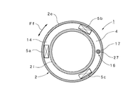
- FIG. 1 is a cross-sectional plan view taken along line AA in FIG.
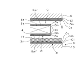
- FIG. 1 is an enlarged view of a portion including a pressure detection element in FIG.
- FIG. 1 is an enlarged view of a portion including a connector portion in FIG.
- FIG. 1 is a cross-sectional plan view taken along line AA in FIG.
- FIG. 6 is a cross-sectional plan view corresponding to the line AA in FIG. 1 in a cylinder internal pressure sensor according to another modified embodiment of the present invention;
- FIG. 6 is a cross-sectional plan view corresponding to the line AA in FIG. 1 in a cylinder internal pressure sensor according to another modified embodiment of the present invention;
- SYMBOLS 1 Engine cylinder internal pressure sensor
- 2 Housing unit
- 2e Outer cylinder part
- 2i Inner cylinder part
- 2es Elastic part
- 2is Elastic part
- 3 Pressure receiving ring block part
- 3f Front surface of pressure receiving ring block part
- 3r rear surface of pressure-receiving ring block portion
- 4 one electrode portion, 5a, 5b, 5c ...: pressure detection element, 5af ...: front surface of pressure detection device, 5ar ...: rear surface of pressure detection device
- 6 support ring Block part
- 6f Front surface of support ring block part
- 7 The other electrode, 10a ...: Spacer, 10as ...: Spacer, 10at: Spacer, 11e: Bent part (or curved part), 11i: Bent part (or curved part) ), 12: pressure-receiving ring body, 13: insulating block, 14: alignment adjustment layer, 15: lead, 16: connector, 17: spring, Ec
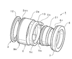
- FIG. 1 shows a configuration of a main part of the cylinder internal pressure sensor 1.
- a housing unit 2 includes an outer cylinder part 2e having a large diameter and an inner cylinder part 2i having a small diameter.
- the outer tube portion 2e and the inner tube portion 2i are integrally formed of an alloy material having excellent heat resistance, and elastic portions 2es and 2is having elasticity in the axial direction Fs are provided in the intermediate portion Xm in the axial direction Fs, respectively.
- the intermediate portion Xm is selected at a position closer to the front of the housing unit 2, preferably a position about several mm from the front end of the housing unit 2.
- the lower side is the front. Further, as shown in FIG.
- the elastic portions 2es and 2is are formed by bent portions 11e and 11i, respectively. That is, the elastic part 2es of the outer cylinder part 2e is formed by a bent part 11e in which the outer peripheral surface of the intermediate part Xm is bulged in the central direction, and the outer peripheral surface is surrounded by a groove having a trapezoidal (rectangular) cross section.
- the elastic portion 2is of the inner cylindrical portion 2i is formed by a bent portion 11i that bulges the inner peripheral surface of the intermediate portion Xm in the radial direction, and has a cross section on the inner peripheral surface.
- a concave groove having a trapezoidal (rectangular) shape is provided in a ring shape along the circumferential direction Ff.
- the outer cylinder part 2e and the inner cylinder part 2i are formed thin from the intermediate part Xm to the front end, and at least the intermediate part Xm has elasticity (spring property) in the axial direction Fs. Accordingly, constricted (bellows-like) elastic portions 2es and 2is are provided in the intermediate portion Xm of the housing unit 2. As described above, if the elastic portions 2es and 2is are provided by forming the bent portions 11e and 11i at the intermediate portion Xm of the outer cylinder portion 2e and the inner cylinder portion 2i, a part of the outer cylinder portion 2e and the inner cylinder portion 2i is provided. Therefore, there is an advantage that it can be implemented in an easy and optimum form in manufacturing.
- the pressure-receiving ring block portion 3 includes a pressure-receiving ring main body portion 12 disposed on the front side and an insulating block portion 13 that contacts the pressure-receiving ring main body portion 12 by being disposed on the rear side.
- the front surface of the pressure receiving ring body portion 12 becomes the front surface 3f of the pressure receiving ring block portion 3, and the front surface 3f becomes a pressure receiving surface that receives the internal pressure Pc.
- the pressure receiving ring main body 12 is integrally formed in a ring shape with an alloy material having excellent heat resistance, and the cross section is formed into a T shape with a wide portion and a narrow portion as shown in FIG. And the wide part in the pressure receiving ring main-body part 12 accommodates so that between the outer cylinder part 2e and the inner cylinder part 2i located ahead of the intermediate part Xm of the housing unit 2 may be accommodated, and the inner peripheral surface of the outer cylinder part 2e In addition, the outer peripheral surface of the inner cylinder portion 2i is hermetically fixed by welding portions 21 and 22 using laser welding or the like so that the combustion gas in the combustion chamber Rb does not enter the cylinder internal pressure sensor 1. At this time, the narrow portion of the pressure-receiving ring main body 12 is brought behind the elastic portions 2e and 2i through the elastic portions 2e and 2i.
- the insulating block 13 is integrally formed in a ring shape with a rigid insulating material and has a rectangular cross section. Therefore, the rear surface of the insulating block portion 13 becomes the rear surface 3r of the pressure receiving ring block portion 3. Further, one electrode portion 4 is provided on the rear surface 3 r of the pressure receiving ring block portion 3.
- the rear surface 3r of the pressure-receiving ring block portion 3, that is, the rear surface of the insulating block portion 13 is an inner layer Ci using Ti (titanium) serving as an adhesion strengthening layer and a diffusion prevention layer, as shown in FIG.
- An intermediate layer Cm using Pt (platinum) and an outer layer Ce using Au (gold) as a diffusion layer are coated, and on the bonding layer C, Au—Sn (gold-tin) is coated.
- An alignment adjustment layer 14 is formed by coating as a melt-type bonding layer having a predetermined thickness Ls.
- the alignment adjustment layer 14 has an alignment adjustment function that absorbs variations in dimensions and angles of three pressure detection elements 5a, which will be described later, and also serves as one electrode portion 4 of the pressure detection elements 5a. Therefore, the thickness Ls of the alignment adjustment layer 14 is selected to be a dimension capable of absorbing variations such as dimensions and angles of the three (at least one) pressure detection elements 5a.
- each layer Ci, Cm, Ce may be composed of a single element or an alloy containing a single element.
- the alignment adjustment layer 14 serving as a melt-type bonding layer includes other metals having eutectic phenomena such as Ag—Cu—Sn, Au—Ge, Au—Pd, Ag—Pd, Ag—Sn, and Cu—Sb. (Alloy) can be used. Each of these layers may be used as solder or brazing material. Therefore, the alignment adjustment layer 14 serving as the melt-type bonding layer and the outer layer Ce serving as the diffusion layer need to be combined. For example, when Au—Sn is used for the alignment adjustment layer 14, Au or Sn is used as the outer layer Ce.
- the material of the diffusion layer (outer layer Ce) needs to be aligned with the alignment adjustment layer 14, for example, Sn needs to be used, and Ag or Pd is used for the alignment adjustment layer 14. It is necessary to select a single material or a composite material among the constituent materials.
- Each pressure detecting element 5a is excellent in heat resistance and is a single crystal material having a spontaneous polarization without a Curie point that can obtain stable piezoelectric conversion characteristics even in a wide temperature range, specifically, LTG (La 3 Ta 0.5 Ga 5.5 O 14 ), LTGA (La 3 Ta 0.5 Ga 4.8 Al 0.2 O 14 ), LGS (La 3 Ga 5 SiO 14 ) and other single crystal materials such as LNG, LGSA, LNGA, CAAS, CTGS Use to make.
- LTG La 3 Ta 0.5 Ga 5.5 O 14
- LTGA La 3 Ta 0.5 Ga 4.8 Al 0.2 O 14
- LGS La 3 Ga 5 SiO 14
- other single crystal materials such as LNG, LGSA, LNGA, CAAS, CTGS Use to make.
- Each pressure detecting element 5a is sandwiched between the insulating block 13 described above and a support ring block 6 described later, and the front and rear surfaces are the rear surface of the insulating block 13 (alignment adjusting layer 14).
- the inner layer Ci, the intermediate layer Cm, and the outer layer Ce is coated.
- the alignment adjustment layer 14 provided on the rear surface 3r of the insulating block portion 13 before the heat treatment is directed upward.
- the three pressure detecting elements 5a, 5b, 5c are placed on the alignment adjustment layer 14 at equal intervals as shown in FIG.
- the front surface 6f of the support ring block 6 is applied to the rear surface 5ar (upper surface) of each pressure detection element 5a, and pressure is applied from above so that a uniform force is applied to each pressure detection element 5a.
- heating is performed in a reflow continuous furnace set to a predetermined temperature environment. As a result, as shown in FIG.
- the upper surface is in surface contact with the front surface 6f of the support ring block portion 6 respectively. That is, alignment adjustment is performed in which the alignment adjustment layer 14 absorbs variations such as dimensions and angles of the pressure detection elements 5a, 5b, and 5c.
- the bonding layers C provided on the front surfaces 5af of the pressure detecting elements 5a are welded to the alignment adjusting layer 14 and the bonding layers C provided on the rear surfaces 5ar of the pressure detecting elements 5a. Are welded to the bonding layer C provided on the front surface 6f of the support ring block portion 6.
- the insulating block portion 13, the pressure detecting elements 5a, and the support ring block portion 6 are integrally bonded. That is, the alignment adjustment step and the assembly step are performed together (simultaneously).
- the front end portion of the support ring block portion 6 is accommodated between the outer cylindrical portion 2e and the rear end portion of the inner cylindrical portion 2i, and a welded portion is formed on the inner peripheral surface of the outer cylindrical portion 2e and the outer peripheral surface of the inner cylindrical portion 2i. It fixes with 23,24.
- the support ring block portion 6 closes the rear end between the outer cylindrical portion 2e and the inner cylindrical portion 2i as shown in FIG.
- the front surface 6f of the ring block portion 6 serves as a support surface that supports the pressure detection elements 5a, 5b, and 5c. Further, the support ring block portion 6 also serves as the other electrode 7 (ground) of each pressure detection element 5a, 5b, 5c.
- the alignment adjustment layer 14 for the pressure detecting elements 5a using a melt-type bonding layer such as Au—Sn having a predetermined thickness Ls is provided on the rear surface 3r of the pressure receiving ring block portion 3, the pressure receiving ring block portion
- the alignment adjustment layer 14 for the pressure detecting elements 5a using a melt-type bonding layer such as Au—Sn having a predetermined thickness Ls is provided on the rear surface 3r of the pressure receiving ring block portion 3, the pressure receiving ring block portion
- the pressure receiving ring block portion By using the rear surface 3r 3 and the front surface 6f of the support ring block 6 and the alignment adjustment layer 14, it is possible to easily perform accurate alignment adjustment for each pressure detection element 5a. Therefore, even when three (at least one) pressure detection elements 5a are used, variations in dimensions and angles can be absorbed to further improve detection accuracy.
- the alignment adjustment layer 14 also functions as one electrode portion 4 provided on the rear surface 3r of the pressure receiving ring block portion 3. Therefore, the lead (shield cable) 14 led out is connected to the solidified alignment adjustment layer 14 (electrode 4). In this case, the electrode 4 and the lead 14 are connected via the connector portion 16.
- FIG. 4 shows an enlarged connection structure between the lead 15 and the electrode 4. The lead 15 introduced from the outside penetrates the support ring block portion 6 and the tip thereof faces the electrode 4. At this time, the lead 15 penetrating the support ring block portion 6 is held by the caulking pipe 25 and the insulating pipe 26 as shown in FIG.
- the spring holding terminal 27 of the connector portion 16 to which the tip of the lead 15 is connected is attached to the tip of the insulating pipe 26. As shown in FIG. 2, the spring holding terminal 27 is arranged in a space between the support ring block portion 6 and the insulating block portion 13 where the pressure detection elements 5 a. Then, one end of the compressed spring 17 is attached to the spring holding terminal 27, and the other end of the spring 17 is pressed against the upper surface of the electrode 4. Therefore, if such a connector part 16 is provided, the lead 15 can be reliably connected to the electrode 4 and a highly reliable connection can be made.
- the cylinder internal pressure sensor 1 is in contact with the one electrode portion 4 provided on the rear surface 3r of the pressure receiving ring block portion 3 whose front surface 3f is a pressure receiving surface, and is equally spaced along the circumferential direction Ff.
- the manufacturing (processing) of the pressure detection elements 5a is facilitated, and the yield and mass productivity are improved. This can contribute to improvement and further cost reduction, and is less likely to cause defects such as cracks, thereby contributing to improved reliability.
- the cylinder internal pressure sensor 1 is entirely covered with a cylindrical (ring-shaped) housing unit 2 or the like, and therefore, from a severe temperature environment or vibration environment when detecting the combustion pressure of the engine,
- the entire detection structure such as the pressure detection elements 5a... And the electrodes 4 and 7 is effectively protected, and stable mounting and stable operation with respect to the cylinder Ec are ensured. Therefore, as shown by a phantom line in FIG. 1, it can easily be mounted on the outer peripheral surface Mas of the tip of the injector Ma that faces the combustion chamber Rb of an engine such as an automobile and injects fuel into the cylinder Ec.
- the cylinder internal pressure sensor 1 can be assembled together with the injector Ma as a part of the injector Ma. That is, it is not necessary to form a separate through-hole at a predetermined position of the cylinder Ec and to attach it independently to this through-hole with a high airtight structure.
- the pressure-receiving ring main body portion 12 constituting the pressure-receiving ring block portion 3 is supported by the elastic portions 2es and 2is having elasticity in the axial direction Fs, so that the displacement of the pressure-receiving ring main body portion 12 by the internal pressure Pc ( Pressure) is stably (equally) and reliably transmitted to each of the pressure detecting elements 5a through the elastic parts 2es and 2is that expand and contract, and highly accurate pressure detection is performed.
- the pressure detection elements 5a, 5b, and 5c are aligned by the alignment adjustment layer 14, as illustrated, even when three pressure detection elements 5a are used, the dimensions and angles are increased. The detection accuracy is further improved by absorbing the variation.
- the number of pressure detecting elements 5a to be used is changed. 2 exemplifies the case where three pressure detecting elements 5a... Are used, the modified embodiment shown in FIG. 9 has six pressure detecting elements 5a, 5b, 5c, 5d, 5e, By using 5f, they are arranged at equal intervals along the circumferential direction Ff.
- the pressure detection elements 5a it is possible to use the pressure detection elements 5a.
- the remaining pressure detection elements can be configured as dummy having the same size. Included in the quantity.
- the use of the cylinder internal pressure sensor 1, that is, the functional component provided with the cylinder internal pressure sensor 1 is changed.
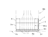
- the embodiment shown in FIG. 1 exemplifies the case where the injector Ma that injects fuel into the cylinder Ec is mounted.
- the modified embodiment shown in FIG. 10 shows the tip of the spark plug Mb that ignites the fuel in the cylinder Ec.
- wears with a part outer peripheral surface Mbs is shown.
- the shape of the cylinder internal pressure sensor 1 with respect to the outer peripheral surface Mbs of the tip end portion of the spark plug Mb is different, the shape of the inner cylinder portion 2i of the housing unit 2 is changed to match the shape of the spark plug Mb to be mounted. Just do it.
- the cylinder internal pressure sensor 1 can be easily attached to various functional parts such as the injector Ma and the spark plug Mb, and the highly versatile cylinder internal pressure sensor 1 can be obtained.
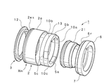
- the modified embodiment shown in FIGS. 11 to 13 is a modification of the mounting form of the pressure detecting elements 5a, and as shown in FIG. 12, the rear surface 3r of the pressure receiving ring block part 3, that is, the insulating block part 13
- the spacers 10a along the circumferential direction Ff are arranged at portions other than the pressure detection elements 5a ... in contact with the rear surface portion (including the alignment adjustment layer 14). If such spacers 10a ... are arranged, the space between the pressure detection elements 5a ... can be filled with the spacers 10a ..., 10as ..., 10at as shown in FIG. As a result, the alignment adjustment can be performed accurately and easily, and can be performed reliably and stably.
- the illustration shows a case where three spacers 10a, 10b, 10c formed of a ceramic material are used. Further, the width of each spacer 10a... Is made substantially equal to the width of the pressure receiving ring block portion 3, and the length in the axial direction Fs is selected corresponding to the length in the axial direction Fs of the pressure detecting elements 5a. In this case, the length in the axial direction Fs is preferably matched with the length in the axial direction Fs of the pressure detection elements 5a, but it is not always necessary to match, and the thickness of the alignment adjustment layer 14 and the spacer 10a. It can be changed depending on the material.
- the thickness of the spacer 10a is slightly thinner than the thickness (0.9 [mm]) of the pressure detection element 5a.
- the thickness (0.89 [mm]) was selected.
- the material of the spacers 10a is not limited to a rigid body, and a material having a certain degree of elasticity may be used. Therefore, the thickness of the spacers 10a may be larger than the thickness of the pressure detection elements 5a if necessary.
- symbol 10bh shows the penetration hole for making the spring holding terminal 27 and the spring 17 penetrate.
- the pressure detecting elements 5a and the spacers 10a are alternately arranged along the circumferential direction Ff of the pressure receiving ring block portion 3. By arranging in this way, it is possible to implement in the most desirable form from the viewpoint of balancing the stress when assisting the alignment adjustment and stabilizing the adjustment action. It is desirable that the pressure detection elements 5a and the spacers 10a are alternately arranged. However, it is not always necessary to arrange the pressure detection elements 5a and the spacers 10a, and the spacers 10a are present between the pressure detection elements 5a as necessary. It may be a form that does not.
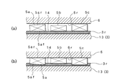
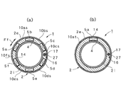
- FIG. 14 (a) and 14 (b) uses the same spacers 10as ..., 10at as the spacers 10a ... shown in FIG. 11, but the number of pressure detection elements 5a ... is changed.
- FIG. 14 (a) uses six pressure detection elements 5a, 5b, 5c, 5d, 5e, and 5f, is arranged at equal intervals along the circumferential direction Ff, and has six spacers 10as, 10bs, 10cs, and 10ds. , 10es, and 10fs are arranged between the pressure detection elements 5a in the same manner as in FIG. Therefore, each spacer 10as can be manufactured in the same manner as the spacer 10a, except that the length in the circumferential direction Ff is different.
- FIG. 14 (a) uses six pressure detection elements 5a, 5b, 5c, 5d, 5e, and 5f, is arranged at equal intervals along the circumferential direction Ff, and has six spacers 10as, 10bs, 10cs
- FIG. 14B shows a case where a single pressure detecting element 5a is used and arranged at a predetermined position in the circumferential direction Ff.
- a single spacer 10at having an overall shape C-shaped it can be implemented in the same manner as in FIG.
- the spacer 10at even one pressure detection element 5a can be implemented. Therefore, by using the spacers 10a,..., 10at shown in FIGS. 11 to 14, in addition to the effects described above, the mechanical strength when the pressure detection elements 5a are assembled can be improved. Further, it is possible to contribute to cost reduction accompanying reduction in the number of pressure detection elements 5a.
- FIG. 9 to FIG. 14 the same parts as those in FIG. 1 to FIG. 8 are given the same reference numerals to clarify the configuration, and detailed description thereof is omitted.
- the elastic portions 2es and 2is are provided by forming the bent portions 11e and 11i
- the elastic portions 2es and 2is may be formed by a curved portion such as a semicircular shape or a plurality of bent portions such as a bellows shape. .. (Or curved portion) 11e..., 11i.
- the injector Ma and the ignition plug Mb were applied as a functional component was shown, it is also possible to combine with other sensors (functional components), such as a temperature sensor.
- the pressure receiving ring block portion 3 is configured by combining the pressure receiving ring main body portion 12 and the insulating block portion 13, it may be an integral type.
- the alignment adjustment layer 14 for adjusting the alignment with respect to each pressure detecting element 5a is provided on the rear surface 3r of the pressure receiving ring block portion 3 is illustrated. You may provide in the front surface 6f of the support ring block part 6 instead of 3r. Moreover, although the case where the alignment adjustment layer 14 is provided on the upper surface of the bonding layer C is shown, when the bonding layer C is not provided, the rear surface 3r of the pressure receiving ring block portion 3 or the front surface 6f of the support ring block portion 6 is shown. You may provide directly.
- the alignment adjustment layer 14 is preferably provided on the rear surface 3r of the pressure receiving ring block portion 3 or the front surface 6f of the support ring block portion 6, but the front surface 5af of the pressure detection elements 5a ... or the rear surface 5ar of the pressure detection elements 5a ... It does not exclude the case where it is provided in....
- the alignment adjusting layer 14 is not necessarily provided when the pressure detecting elements 5a, which can ignore variations in dimensions and angles due to improvement in processing accuracy, are used.
- the structure for connecting one electrode 4 and the lead 15 is not limited to the illustrated configuration using the spring 17, and any other connection is possible as long as the electrode 4 and the lead 15 can be connected. It does not exclude the structure.
- the spark plug Mb includes various spark plugs such as a spark plug and a glow plug, and functional parts Ma and Mb facing the combustion chamber Rb of the engine are attached to the cylinder Ec as illustrated. In addition to the case, the case of attaching to the piston is also included.
- the cylinder internal pressure sensor according to the present invention can be used when detecting internal pressure of a cylinder constituting an internal combustion engine in various other applications including an internal combustion engine represented by an automobile engine.
Landscapes
- Engineering & Computer Science (AREA)
- Chemical & Material Sciences (AREA)
- Combustion & Propulsion (AREA)
- Physics & Mathematics (AREA)
- General Physics & Mathematics (AREA)
- Mechanical Engineering (AREA)
- General Engineering & Computer Science (AREA)
- Measuring Fluid Pressure (AREA)
Abstract
L'invention concerne un capteur de pression interne de cylindre comprenant : une unité de boîtier (2) qui est constituée d'une section cylindrique extérieure (2e) et d'une section cylindrique intérieure (2i) obtenues en façonnant des portions souples (2es, 2is), lesquelles présentent une souplesse dans le sens axial (Fs), dans une section centrale (Xm) dans le sens axial (Fs) ; une section de bloc annulaire récepteur de pression (3), laquelle est fixée hermétiquement entre la section cylindrique extérieure (2e) et la section cylindrique intérieure (2i) en direction des portions souples (2es, 2is), passe à travers les portions souples (2e, 2i) et s'approche de l'arrière des portions souples (2e, 2i), et dont la surface frontale (3f) est une surface réceptrice de pression ; au moins un élément de détection de pression (5a, 5b, 5c...) qui est disposé à une position spécifique dans le sens périphérique (Ff), lequel est en contact avec une section d'électrode (4) réalisée sur la surface arrière (3r) de la section de bloc annulaire récepteur de pression (3) et sur lequel agit la pression interne (Pc) de la section de bloc annulaire récepteur de pression (3) ; et une section de bloc annulaire support (6), laquelle est fixée entre la section cylindrique extérieure (2e) et la section cylindrique intérieure (2i), dont la surface frontale (6f) est une surface support destinée à supporter les éléments de détection de pression (5a, 5b, 5c...) et qui est combinée avec une autre électrode (7).
Priority Applications (5)
| Application Number | Priority Date | Filing Date | Title |
|---|---|---|---|
| EP12765630.4A EP2693185B1 (fr) | 2011-03-31 | 2012-03-29 | Capteur de pression interne de cylindre pour moteur |
| US14/004,282 US8915125B2 (en) | 2011-03-31 | 2012-03-29 | Cylinder internal-pressure sensor for engine |
| JP2013507195A JP5981910B2 (ja) | 2011-03-31 | 2012-03-29 | エンジン用シリンダ内圧センサ |
| HK14104301.0A HK1191092B (en) | 2011-03-31 | 2012-03-29 | Cylinder internal-pressure sensor for engine |
| CN201280016410.4A CN103460005B (zh) | 2011-03-31 | 2012-03-29 | 发动机用气缸内压传感器 |
Applications Claiming Priority (2)
| Application Number | Priority Date | Filing Date | Title |
|---|---|---|---|
| PCT/JP2011/001976 WO2012131788A1 (fr) | 2011-03-31 | 2011-03-31 | Capteur de pression interne de cylindre pour moteur |
| JPPCT/JP2011/001976 | 2011-03-31 |
Publications (1)
| Publication Number | Publication Date |
|---|---|
| WO2012132450A1 true WO2012132450A1 (fr) | 2012-10-04 |
Family
ID=46929637
Family Applications (2)
| Application Number | Title | Priority Date | Filing Date |
|---|---|---|---|
| PCT/JP2011/001976 Ceased WO2012131788A1 (fr) | 2011-03-31 | 2011-03-31 | Capteur de pression interne de cylindre pour moteur |
| PCT/JP2012/002182 Ceased WO2012132450A1 (fr) | 2011-03-31 | 2012-03-29 | Capteur de pression interne de cylindre pour moteur |
Family Applications Before (1)
| Application Number | Title | Priority Date | Filing Date |
|---|---|---|---|
| PCT/JP2011/001976 Ceased WO2012131788A1 (fr) | 2011-03-31 | 2011-03-31 | Capteur de pression interne de cylindre pour moteur |
Country Status (5)
| Country | Link |
|---|---|
| US (1) | US8915125B2 (fr) |
| EP (1) | EP2693185B1 (fr) |
| JP (1) | JP5981910B2 (fr) |
| CN (1) | CN103460005B (fr) |
| WO (2) | WO2012131788A1 (fr) |
Cited By (3)
| Publication number | Priority date | Publication date | Assignee | Title |
|---|---|---|---|---|
| JP2014163881A (ja) * | 2013-02-27 | 2014-09-08 | Citizen Finetech Miyota Co Ltd | 圧力検出装置 |
| JP2015190333A (ja) * | 2014-03-27 | 2015-11-02 | Tdk株式会社 | 燃焼圧センサ |
| WO2020138016A1 (fr) * | 2018-12-28 | 2020-07-02 | 川崎重工業株式会社 | Navire |
Families Citing this family (3)
| Publication number | Priority date | Publication date | Assignee | Title |
|---|---|---|---|---|
| JP6008087B2 (ja) * | 2012-03-27 | 2016-10-19 | 株式会社ケーヒン | 筒内圧センサ付き燃料噴射弁 |
| JP6066767B2 (ja) * | 2013-02-28 | 2017-01-25 | シチズンファインデバイス株式会社 | 内燃機関用燃焼圧センサ及びその製造方法。 |
| US10221782B2 (en) * | 2014-04-04 | 2019-03-05 | Honda Motor Co., Ltd. | In-cylinder pressure detecting apparatus |
Citations (6)
| Publication number | Priority date | Publication date | Assignee | Title |
|---|---|---|---|---|
| JPS58144247U (ja) * | 1982-03-24 | 1983-09-28 | 日産自動車株式会社 | 内燃機関の筒内圧力センサ取付装置 |
| JPS59211835A (ja) * | 1983-05-18 | 1984-11-30 | Nissan Motor Co Ltd | 筒内圧検出装置 |
| JPS63235841A (ja) * | 1987-03-25 | 1988-09-30 | Ngk Spark Plug Co Ltd | ガスケツト型圧力センサ− |
| JPH0434327A (ja) | 1990-05-30 | 1992-02-05 | Nissan Motor Co Ltd | 燃焼圧力センサ |
| JPH1194675A (ja) | 1997-09-19 | 1999-04-09 | Ngk Spark Plug Co Ltd | 圧力センサ |
| JP2000277233A (ja) | 1999-03-24 | 2000-10-06 | Ngk Spark Plug Co Ltd | 圧力センサ内蔵スパークプラグ |
Family Cites Families (16)
| Publication number | Priority date | Publication date | Assignee | Title |
|---|---|---|---|---|
| JPH06307953A (ja) * | 1993-04-27 | 1994-11-04 | Hitachi Ltd | 物理量検出装置 |
| US5831263A (en) * | 1994-04-26 | 1998-11-03 | Hitachi, Ltd. | In-cylinder pressure sensing apparatus for multi-cylinder engine |
| US7152478B2 (en) * | 2000-07-20 | 2006-12-26 | Entegris, Inc. | Sensor usable in ultra pure and highly corrosive environments |
| US6617764B2 (en) * | 2000-09-13 | 2003-09-09 | University Of Dayton | High temperature piezoelectric sensor |
| JP4620882B2 (ja) * | 2001-02-20 | 2011-01-26 | 日本特殊陶業株式会社 | 圧力センサ内蔵プラグ |
| US6701775B1 (en) * | 2002-02-15 | 2004-03-09 | Dana Corporation | Pressure sensor apparatus for measuring pressures including knock conditions in engine cylinders |
| CA2476095A1 (fr) * | 2002-02-15 | 2003-08-28 | Dana Corporation | Joint de culasse multicouche comportant un dispositif de detection de pression integre pour mesurer les pressions dans les cylindres d'un moteur |
| WO2003071119A2 (fr) * | 2002-02-15 | 2003-08-28 | Dana Corporation | Dispositif de detection de pression destine a mesurer des pressions associees a des conditions de cognement dans des cylindres de moteur |
| US6739183B1 (en) * | 2002-02-15 | 2004-05-25 | Dana Corporation | Multiple-layer cylinder head gasket with integral pressure sensor apparatus for measuring pressures within engine cylinders |
| JP2004045184A (ja) * | 2002-07-11 | 2004-02-12 | Denso Corp | 半導体力学量センサ |
| US7197937B2 (en) * | 2005-01-26 | 2007-04-03 | Sensata Technologies, Inc. | Hermetic pressure sensing device |
| WO2006089446A1 (fr) * | 2005-02-24 | 2006-08-31 | Kistler Holding Ag | Composant pour capteurs de force ou de pression, dont les elements sont maintenus les uns avec les autres par un film electro-isolant |
| GB0609519D0 (en) * | 2006-05-12 | 2006-06-21 | Delphi Tech Inc | Fuel injector |
| EP2331852A2 (fr) * | 2008-10-03 | 2011-06-15 | Federal-Mogul Corporation | Garniture de capteur de compression et procédé de fabrication |
| EP2438330A2 (fr) * | 2009-06-01 | 2012-04-11 | Federal-Mogul Corporation | Ensemble joint-capteur de compression et son procédé de fabrication |
| JP2011022071A (ja) * | 2009-07-17 | 2011-02-03 | Ngk Spark Plug Co Ltd | 燃焼圧センサ |
-
2011
- 2011-03-31 WO PCT/JP2011/001976 patent/WO2012131788A1/fr not_active Ceased
-
2012
- 2012-03-29 WO PCT/JP2012/002182 patent/WO2012132450A1/fr not_active Ceased
- 2012-03-29 US US14/004,282 patent/US8915125B2/en not_active Expired - Fee Related
- 2012-03-29 CN CN201280016410.4A patent/CN103460005B/zh not_active Expired - Fee Related
- 2012-03-29 JP JP2013507195A patent/JP5981910B2/ja not_active Expired - Fee Related
- 2012-03-29 EP EP12765630.4A patent/EP2693185B1/fr active Active
Patent Citations (6)
| Publication number | Priority date | Publication date | Assignee | Title |
|---|---|---|---|---|
| JPS58144247U (ja) * | 1982-03-24 | 1983-09-28 | 日産自動車株式会社 | 内燃機関の筒内圧力センサ取付装置 |
| JPS59211835A (ja) * | 1983-05-18 | 1984-11-30 | Nissan Motor Co Ltd | 筒内圧検出装置 |
| JPS63235841A (ja) * | 1987-03-25 | 1988-09-30 | Ngk Spark Plug Co Ltd | ガスケツト型圧力センサ− |
| JPH0434327A (ja) | 1990-05-30 | 1992-02-05 | Nissan Motor Co Ltd | 燃焼圧力センサ |
| JPH1194675A (ja) | 1997-09-19 | 1999-04-09 | Ngk Spark Plug Co Ltd | 圧力センサ |
| JP2000277233A (ja) | 1999-03-24 | 2000-10-06 | Ngk Spark Plug Co Ltd | 圧力センサ内蔵スパークプラグ |
Cited By (5)
| Publication number | Priority date | Publication date | Assignee | Title |
|---|---|---|---|---|
| JP2014163881A (ja) * | 2013-02-27 | 2014-09-08 | Citizen Finetech Miyota Co Ltd | 圧力検出装置 |
| JP2015190333A (ja) * | 2014-03-27 | 2015-11-02 | Tdk株式会社 | 燃焼圧センサ |
| WO2020138016A1 (fr) * | 2018-12-28 | 2020-07-02 | 川崎重工業株式会社 | Navire |
| JP2020104787A (ja) * | 2018-12-28 | 2020-07-09 | 川崎重工業株式会社 | 船舶 |
| JP7273508B2 (ja) | 2018-12-28 | 2023-05-15 | 川崎重工業株式会社 | 船舶 |
Also Published As
| Publication number | Publication date |
|---|---|
| JPWO2012132450A1 (ja) | 2014-07-24 |
| EP2693185B1 (fr) | 2019-07-31 |
| CN103460005A (zh) | 2013-12-18 |
| US20140083388A1 (en) | 2014-03-27 |
| EP2693185A1 (fr) | 2014-02-05 |
| CN103460005B (zh) | 2016-01-20 |
| US8915125B2 (en) | 2014-12-23 |
| JP5981910B2 (ja) | 2016-08-31 |
| EP2693185A4 (fr) | 2015-01-14 |
| HK1191092A1 (zh) | 2014-07-18 |
| WO2012131788A1 (fr) | 2012-10-04 |
Similar Documents
| Publication | Publication Date | Title |
|---|---|---|
| JP5981910B2 (ja) | エンジン用シリンダ内圧センサ | |
| JP3885515B2 (ja) | 燃焼圧センサ付きグロープラグ | |
| US7492075B2 (en) | Multilayer piezoelectric element, fuel injector having the piezoelectric element and piezoelectric element production method | |
| JP2017032558A (ja) | 圧電型圧力センサ | |
| US20170160153A1 (en) | Piezoelectric pressure sensor and process of manufacturing the same | |
| JP2010139148A (ja) | 燃焼圧力センサ付きグロープラグ及び内燃機関 | |
| JP3123799B2 (ja) | 圧力センサ | |
| JP6286355B2 (ja) | 内燃機関用燃焼圧センサ付き機能部品ユニット | |
| CN104583744B (zh) | 燃烧压力传感器 | |
| HK1191092B (en) | Cylinder internal-pressure sensor for engine | |
| JP2004264037A (ja) | 圧力センサ | |
| JP6231987B2 (ja) | 圧力検出装置 | |
| JP2012042376A (ja) | 温度センサ | |
| JPH09260024A (ja) | 圧力センサ内蔵スパークプラグ | |
| JP2009063256A (ja) | 燃焼圧力センサ付きグロープラグ | |
| JP6074288B2 (ja) | 圧力検出装置 | |
| JP2020020635A (ja) | 圧力検出装置 | |
| JP2004257890A (ja) | ガスセンサ | |
| JP5651550B2 (ja) | 温度センサ及び温度センサの製造方法 | |
| JP6937148B2 (ja) | 圧力検出装置、圧力検出装置の製造方法 | |
| JP2013015397A (ja) | 温度センサの製造方法及び温度センサ | |
| JP2018163082A (ja) | 圧力検出装置、内燃機関用部品 | |
| JP2004233268A (ja) | ガスセンサ | |
| JP2020183880A (ja) | 圧力センサ | |
| JP2018136286A (ja) | 燃焼圧センサ |
Legal Events
| Date | Code | Title | Description |
|---|---|---|---|
| 121 | Ep: the epo has been informed by wipo that ep was designated in this application |
Ref document number: 12765630 Country of ref document: EP Kind code of ref document: A1 |
|
| ENP | Entry into the national phase |
Ref document number: 2013507195 Country of ref document: JP Kind code of ref document: A |
|
| WWE | Wipo information: entry into national phase |
Ref document number: 14004282 Country of ref document: US |
|
| NENP | Non-entry into the national phase |
Ref country code: DE |