WO2012132481A1 - Dispositif de conversion de couleurs, procédé de conversion de couleurs, programme et dispositif de séparation de couleurs - Google Patents
Dispositif de conversion de couleurs, procédé de conversion de couleurs, programme et dispositif de séparation de couleurs Download PDFInfo
- Publication number
- WO2012132481A1 WO2012132481A1 PCT/JP2012/050049 JP2012050049W WO2012132481A1 WO 2012132481 A1 WO2012132481 A1 WO 2012132481A1 JP 2012050049 W JP2012050049 W JP 2012050049W WO 2012132481 A1 WO2012132481 A1 WO 2012132481A1
- Authority
- WO
- WIPO (PCT)
- Prior art keywords
- color
- granularity
- conversion
- unit
- target value
- Prior art date
- Legal status (The legal status is an assumption and is not a legal conclusion. Google has not performed a legal analysis and makes no representation as to the accuracy of the status listed.)
- Ceased
Links
Images




Classifications
-
- H—ELECTRICITY
- H04—ELECTRIC COMMUNICATION TECHNIQUE
- H04N—PICTORIAL COMMUNICATION, e.g. TELEVISION
- H04N1/00—Scanning, transmission or reproduction of documents or the like, e.g. facsimile transmission; Details thereof
- H04N1/40—Picture signal circuits
- H04N1/40012—Conversion of colour to monochrome
-
- H—ELECTRICITY
- H04—ELECTRIC COMMUNICATION TECHNIQUE
- H04N—PICTORIAL COMMUNICATION, e.g. TELEVISION
- H04N1/00—Scanning, transmission or reproduction of documents or the like, e.g. facsimile transmission; Details thereof
- H04N1/46—Colour picture communication systems
- H04N1/56—Processing of colour picture signals
- H04N1/60—Colour correction or control
- H04N1/6016—Conversion to subtractive colour signals
- H04N1/6022—Generating a fourth subtractive colour signal, e.g. under colour removal, black masking
Definitions
- the present invention relates to a color conversion device, a color conversion method, a program, and a color separation device for converting the color of a printed matter formed using a plurality of types of color materials.
- CMYK ink CMYK ink
- Japanese Patent Application Laid-Open No. 2000-78418 discloses a method and apparatus for determining a use amount of K toner by predicting an image quality prediction value related to the image quality of an image printed out from a detected predetermined color signal. .
- Japanese Unexamined Patent Application Publication No. 2009-241609 discloses an apparatus and method for determining whether or not to form chromatic (or achromatic) dots based on an input signal. For example, it is described that dots are formed using light K ink instead of dark K ink in a color region where the dot shape is conspicuous and graininess deteriorates.
- the present invention has been made to solve the above-described problems, and an object of the present invention is to provide a color conversion device, a color conversion method, and a program capable of forming a printed material that achieves both improved graininess and reduced cost.
- the color conversion device is a device for converting the color of a printed matter formed using a plurality of types of color materials, and for inputting a device color signal associated with the amount of use of each color material.
- a target value setting unit that sets a target value of the granularity for each granularity adjustment region extracted by the adjustment region extraction unit, and a granularity calculation unit that calculates the granularity in each granularity adjustment region
- the granularity calculated by the granularity calculating unit is closer to the target value set by the target value setting unit than before the conversion, and the same color in the device-independent color space Fit in range So that the, and having a color matching conversion section for converting the device color signal of the granularity adjustment region to the new device color signal.
- the adjustment area extraction unit that extracts at least one granularity adjustment area for adjusting the granularity of the image from the image area represented by the input device color signal, and each of the extracted granularity adjustment areas.
- the color matching conversion unit converts the device color signal so that the total use amount of each color material in the granularity adjustment region is larger than that before the conversion. Is preferred.
- the plurality of types of color materials include an achromatic color material and a plurality of chromatic color materials, and the color on the printed matter by the achromatic color material can be reproduced by combining the plurality of chromatic color materials.
- the color matching unit reduces the amount of the achromatic color material used in the granularity adjustment region before conversion, and converts the total amount of the chromatic color materials in the granularity adjustment region. It is preferable to convert the device color signal so as to increase more than before. In this way, by increasing the total amount of each color material used for the formation of the printed material, the desired granularity adjustment region while appropriately reducing the granularity and appropriately increasing the amount of color material used. Can be obtained.
- the color matching conversion unit converts the device color signal so that the total amount of each color material used in the granularity adjustment region is smaller than that before conversion. Is preferred.
- the plurality of types of color materials include an achromatic color material and a plurality of chromatic color materials, and the color on the printed matter by the achromatic color material can be reproduced by combining the plurality of chromatic color materials.
- the color matching unit increases the usage amount of the achromatic color material in the granularity adjustment region before conversion, and converts the total usage amount of the plurality of chromatic color materials in the granularity adjustment region. It is preferable to convert the device color signal so that it is smaller than before. In this way, by reducing the total amount of each color material used to form the printed material, the granularity is appropriately increased, and the amount of the color material used is appropriately decreased, while being desired in the granularity adjustment region. Can be obtained.
- the adjustment area extraction unit extracts a face area as the granularity adjustment area.
- the adjustment area extraction unit extracts an achromatic flat area whose saturation is lower than the first threshold and whose spatial frequency is lower than the second threshold as the granularity adjustment area.
- the color conversion method is a method for converting the color of a printed matter formed using a plurality of types of color materials, and is an input for inputting device color signals respectively associated with the usage amounts of the color materials.
- An extraction step of extracting at least one granularity adjustment region for adjusting the granularity of the image from the image region represented by the input device color signal, and for each of the extracted granularity adjustment regions A setting step for setting each target value of the granularity, a calculation step for calculating the granularity in each granularity adjustment region, and the calculated granularity is set to the target before the conversion.
- a program according to the present invention is a program for converting the color of a printed matter formed using a plurality of types of color materials, and the computer outputs device color signals respectively associated with the usage amounts of the color materials.
- An input color signal input unit an adjustment region extraction unit that extracts at least one granularity adjustment region for adjusting the granularity of an image from the image region represented by the device color signal input by the color signal input unit;
- a target value setting unit that sets a target value of the granularity for each granularity adjustment region extracted by the adjustment region extraction unit, and a granularity calculation unit that calculates the granularity in each granularity adjustment region
- the granularity calculated by the granularity calculating unit is closer to the target value set by the target value setting unit than before conversion, and is a device-independent color. To fit the color matching range over between, characterized in that to function as the color matching conversion section for converting the device color signal of the granularity adjustment region to the new device color signal.
- the plate separation apparatus includes an adjustment region extraction unit that extracts at least one granularity adjustment region for adjusting the granularity of an image from an image region represented by an input device color signal, and the adjustment region extraction A target value setting unit that sets a target value of the granularity for each granularity adjustment region extracted by a unit, a granularity calculation unit that calculates the granularity in each granularity adjustment region, Separation that determines one separation condition information from among a plurality of separation condition information that separates the input device color signal into device color signals that are associated with the usage amounts of multiple types of color materials.
- a condition determining unit wherein the color separation condition determining unit is configured such that the granularity calculated by the granularity calculating unit is set by the target value setting unit more than other color separation conditions. The one minute so that it is close to the value And determining the condition information.
- At least one granularity adjustment region for adjusting the granularity of an image is extracted from the image region represented by the input device color signal, and extracted.
- a target value of the granularity is set for each of the granularity adjustment areas, and the granularity in each granularity adjustment area is calculated, and the granularity is closer to the target value than before the conversion.
- the device color signal in the degree adjustment area was converted.
- At least one granularity adjustment region for adjusting the granularity of the image is extracted from the image region represented by the input device color signal, and each of the extracted granularities is extracted.
- a granularity target value is set for each of the adjustment areas, the granularity is calculated in each granularity adjustment area, and a plurality of color separations are made so as to be closer to the target value than other color separation conditions.
- One separation condition information was decided from the condition information.
- FIG. 1 is an electrical schematic block diagram of a color conversion apparatus according to a first embodiment.
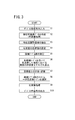
- 3 is a flowchart for explaining the operation of the color conversion apparatus shown in FIG. 2.
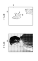
- FIG. 4A is a schematic diagram in which an image represented by a device color signal is visualized.
- FIG. 4B is a schematic explanatory diagram showing the result of extracting the granularity adjustment region by the adjustment region extraction unit of FIG.
- FIG. 5A is a schematic explanatory diagram showing a correspondence relationship between ink types and their usage before each conversion.
- FIG. 5B is a schematic explanatory diagram showing the correspondence between the ink type after GCR conversion and the amount of use.
- FIG. 5C is a schematic explanatory diagram showing the correspondence between the ink type after IGCR conversion and the amount used.
- FIG. 6A is a schematic explanatory diagram showing a uniform color range on a device-independent color space.
- FIG. 6B is a schematic explanatory diagram illustrating a specification example of a candidate table group.
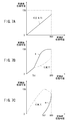
- FIG. 7A is a graph illustrating conversion characteristics of a normal color conversion table that reproduces the gray color.
- FIG. 7B is a graph illustrating the conversion characteristics of the GCR conversion table that reproduces the gray color.
- FIG. 7C is a graph illustrating conversion characteristics of an IGCR conversion table that reproduces the gray color.
- FIG. 8A is a schematic explanatory diagram showing a rectangular area outside the granularity adjustment area.
- FIG. 8A is a schematic explanatory diagram showing a rectangular area outside the granularity adjustment area.
- FIG. 8B is a partially enlarged view of the rectangular area shown in FIG. 8A.
- FIG. 8C is a graph showing a microscopic density profile along the arrow shown in FIG. 8B.
- FIG. 9A is a schematic explanatory diagram showing a rectangular area in the granularity adjustment area.
- FIG. 9B is a partially enlarged view of the rectangular area shown in FIG. 9A.
- FIG. 9C is a graph showing a microscopic density profile along the arrow shown in FIG. 9B.
- It is an electrical schematic block diagram of the plate separation apparatus which concerns on 2nd Embodiment. 12 is a flowchart provided for explaining the operation of the plate separation apparatus shown in FIG.
- FIG. 1 is a schematic explanatory diagram of a printing system 10 incorporating a color conversion device 12 according to the first embodiment (or a color separation device 12A according to the second embodiment).
- the printing system 10 basically includes a color conversion device 12, an image forming device 14, a DTP (Desktop Publishing) device 16, and a database server 18.
- the color conversion device 12, the DTP device 16, and the database server 18 are electrically connected to each other by wire or wireless.
- the color converter 12 converts input image data (device color signal or page description data) from an external device into a device color signal suitable for printing by the image forming apparatus 14. Further, the color conversion device 12 outputs the converted device color signal to the image forming device 14 side.
- the device color signal means a color signal defined by device-dependent data. For example, raster format data (TIFF, bitmap, RAW) having four (CMYK) or three (RGB) color channels. Etc.).
- raster format data TIFF, bitmap, RAW
- CMYK color signal
- RGB three
- the image forming apparatus 14 is electrically connected to the color conversion apparatus 12.
- a serial interface such as USB (Universal Serial Bus), IEEE 1394, Ethernet (registered trademark), a wireless network, or a parallel interface such as Centronics can be applied.
- the image forming apparatus 14 is a so-called inkjet printer that forms an image on the medium by ejecting ink droplets from the recording head 20 while conveying a medium (recording medium) (not shown) in a predetermined direction.
- a medium recording medium
- the substrate of the media paper such as synthetic paper, cardboard, and aluminum vapor-deposited paper, resin such as vinyl chloride and PET, tarpaulin, and the like can be used.
- the recording head 20 has four types of color materials of different colors ⁇ C ink 22c (chromatic color material), M ink 22m (chromatic color material), Y ink 22y (chromatic color material), and K ink 22k (achromatic color material) ⁇ .
- C ink 22c chromatic color material
- M ink 22m chromatic color material
- Y ink 22y chromatic color material
- K ink 22k achromatic color material
- Each line head 24c, 24m, 24y, 24k is formed with a plurality of nozzles (not shown) arranged along the width direction of the medium.
- the C ink 22c, M ink 22m, Y ink 22y, and K ink 22k are accommodated in ink tanks 26c, 26m, 26y, and 26k as containers, respectively.
- the line head 24c discharges the C ink 22c supplied from the ink tank 26c through the plurality of nozzles.
- the line head 24m discharges the M ink 22m supplied from the ink tank 26m through the plurality of nozzles.
- the line head 24y discharges the Y ink 22y supplied from the ink tank 26y through the plurality of nozzles.
- the line head 24k discharges the K ink 22k supplied from the ink tank 26k through the plurality of nozzles.
- various methods can be adopted as a mechanism for ejecting the droplets of the ink 22 by the recording head 20.
- a method of ejecting ink 22 droplets by deformation of an actuator constituted by a piezoelectric element (piezoelectric element) or the like may be applied.
- a thermal jet method may be applied in which bubbles are generated by heating the ink 22 through a heating element such as a heater and the droplets of the ink 22 are ejected with the pressure.
- the recording head 20 is not limited to a line head, and may be a multi-pass method in which an image is formed while reciprocating scanning in the width direction of the medium.
- the DTP device 16 can edit a material composed of characters, figures, patterns, photographs, and the like, and generates an electronic manuscript in a page description language (hereinafter referred to as PDL) by arranging the material for each page.
- PDL is a language that describes image information such as text, graphics, and other format information, position information, and color information (including density information) within a “page” that is an output unit for printing and display.
- the DTP device 16 performs rasterization processing on the electronic document in the PDL format. This rasterization processing includes rasterization processing for converting from the PDL format to the raster format, and color conversion processing using an ICC (International Color Consortium) profile.
- ICC International Color Consortium
- the database server 18 is a device for managing data such as a job ticket for an electronic document ⁇ eg, JDF (Job Definition Format) file ⁇ , color sample data, target profile, or a printing profile suitable for a combination of the image forming apparatus 14 and media. It is.
- JDF Job Definition Format
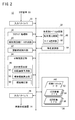
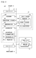
- FIG. 2 is an electrical schematic block diagram of the color conversion device 12 shown in FIG.
- the color conversion device 12 includes an input interface 30 (color signal input unit), a control unit 32, a memory 34 (recording medium), and an output interface 36.
- the memory 34 stores a program for causing the color conversion device 12 (the color separation device 12A) according to the first embodiment (or the second embodiment) to function.
- the input interface 30 receives an electrical signal from an external device. For example, device color signals and PDL data edited and created by the DTP device 16 are acquired. Further, various information such as an ICC profile stored in the database server 18 is acquired.
- the output interface 36 transmits an electrical signal to an external device.
- the device color signal subjected to the color conversion processing according to the present invention is supplied to the image forming apparatus 14.
- This color conversion process is a process for converting only the signal value of the device color signal without changing the type of color plate (for example, CMYK signal data).
- the device color signal before conversion may be referred to as “pre-conversion color signal”
- the device color signal after conversion may be referred to as “post-conversion color signal”.
- the input / output device color signals are associated with the amount of ink 22 used in the image forming apparatus 14. This association can be arbitrarily designed for each color channel. For example, a usage amount of 0% may be assigned at the lowest gradation level, a usage amount of 100% may be assigned at the highest gradation level, and a usage amount may be assigned linearly at an intermediate level.
- the control unit 32 configured by an information processing device such as a CPU includes a rasterization processing unit 38, an analysis image data creation unit 40, an adjustment region extraction unit 42, a target value setting unit 44, and a granularity calculation unit 46.
- the color conversion table determination unit 48 and the color matching conversion unit 50 are provided.
- the rasterization processing unit 38 has the same rasterization function as the DTP device 16.
- the rasterization processing unit 38 performs rasterization processing on the input data according to the type of input data. When the device color signal is directly input to the input interface 30 side, the rasterizing process by this component is not necessary.
- the analysis image data creation unit 40 creates analysis image data from the pre-conversion color signal acquired from the input interface 30 or the rasterization processing unit 38. Specifically, the analysis image data creation unit 40 performs color conversion processing for converting the pre-conversion color signal into device-independent data.
- the device-independent data is data defined by a color system such as HSV (Hue-Saturation-Value), HLS (Hue-Lightness-Saturation), CIELAB, CIEUV, and XYZ.
- the analysis image data creation unit 40 creates L * a * b * data, YCC data, and the like from the pre-conversion color signal using, for example, a print profile corresponding to the image forming apparatus 14.
- the adjustment area extraction unit 42 extracts a granularity adjustment area for adjusting the granularity of the image (hereinafter sometimes simply referred to as “granularity GR”) from a predetermined image area.
- granularity GR a granularity adjustment area for adjusting the granularity of the image
- the target value setting unit 44 sets the target value Gt of the granularity GR for each of the granularity adjustment regions extracted by the adjustment region extraction unit 42.
- the target value Gt may be set according to the attribute of the granularity adjustment region, or may be set with an input operation by the user via the GUI.
- the granularity calculation unit 46 calculates the granularity GR in the granularity adjustment region based on the device color signal and the output characteristics of the image forming apparatus 14.
- the granularity calculation unit 46 predicts the print density (microscopic density profile) based on the device color signal and the output characteristics of the image forming apparatus 14, and the print density prediction unit 52.
- the standard deviation calculation unit 54 that calculates the standard deviation of the print density in a predetermined image area based on the microscopic density profile predicted in step S5, and the standard deviation of the print density calculated by the standard deviation calculation unit 54 is corrected.
- the visual correction unit 56 is configured to acquire the granularity GR as an index associated with the visibility (granularity) of the image.
- the color conversion table determination unit 48 designates a plurality of color conversion tables (hereinafter may be referred to as candidate tables) that can be used for color conversion processing, and also stores a plurality of candidate tables (hereinafter referred to as candidate table groups). Select and determine one color conversion table from among them.
- the color conversion table determination unit 48 includes a granularity comparison unit 58 that compares and evaluates the granularity GR calculated by the granularity calculation unit 46 and the target value Gt set by the target value setting unit 44.
- a table selection unit 60 that selects one color conversion table from the candidate table group based on the comparison / evaluation result in the granularity comparison unit 58 is further provided.
- the color matching conversion unit 50 uses a color conversion table having a predetermined data format to generate a new device color to output the input device color signal so as to be within the color matching range on the device independent color space. Convert to signal. Depending on the type of the color conversion table, either IGCR (Inverse Gray-Component Replacement) conversion, GCR (Gray-Component Replacement) conversion, or equivalent conversion is executed. As in the image forming apparatus 14 shown in FIG. 1, by combining a plurality of chromatic color materials C ink 22c, M ink 22m, and Y ink 22y, the color on the printed matter 28 by the K ink 22k that is an achromatic color material is changed. If reproducible, IGCR conversion and GCR conversion are effective. Details of GCR conversion and IGCR conversion will be described later.
- the memory 34 records print profile data 62 suitable for the image forming apparatus 14, an IGCR conversion table 64 used for IGCR conversion, and a GCR conversion table 66 used for GCR conversion.
- the memory 34 may record pre-conversion color signals, post-conversion color signals, analysis image data, and various types of information necessary for color conversion processing according to the present invention.
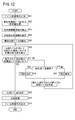
- the color conversion device 12 according to the first embodiment is configured as described above. Next, the operation of the color conversion device 12 will be described with reference to the flowchart of FIG.
- the color conversion device 12 inputs a device color signal via the input interface 30 (step S1). For example, two input forms are assumed.
- the DTP device 16 performs a rasterization process on a PDL-format electronic document created through a predetermined editing process, thereby providing a device color signal (that is, CMYK signal data) used for printing. Is created in advance. Then, the color conversion device 12 inputs the device color signal supplied from the DTP device 16 via the input interface 30.
- a device color signal that is, CMYK signal data
- the DTP device 16 creates an electronic document in PDL format through a predetermined editing process, and supplies the electronic document to the image forming apparatus 14 side in the PDL format.
- the rasterization processing unit 38 reads the print profile data 62 stored in the memory 34 and performs a rasterization process on the input electronic document (PDL format), whereby a device color signal (that is, a print color data) , CMYK signal data).
- the analysis image data creation unit 40 creates analysis image data by performing a predetermined color conversion process on the input device color signal (step S2).
- the analysis image data creation unit 40 creates, for example, YCC data used for a face detection process described later, L * a * b * data used for a color matching conversion process described later, and the like.
- the input device color signal and the generated analysis image data are temporarily recorded in the memory 34.
- the adjustment area extraction unit 42 extracts a granularity adjustment area for adjusting the granularity GR of the image from the image area represented by the device color signal (step S3).
- the adjustment area extraction unit 42 reads the device color signal and the analysis image data from the memory 34, and then extracts the granularity adjustment area by applying various area detection algorithms. A specific example of the algorithm will be described below.
- the detected face area may be set as the granularity adjustment area. This is because the human face is a typical object that is easily evaluated for its quality.
- various known image processing techniques disclosed in Japanese Patent Application Laid-Open Nos. 2006-285959 and 2007-148537 may be applied.
- the type of analysis image data used for this detection is not limited.
- a known detection method mounted in an input device such as a digital camera can be applied as it is.
- an achromatic flat region may be set as the granularity adjustment region.
- the human standard visual response characteristic (contrast resolution) is maximized because the color is gray and the spatial frequency band is around 1 Cy / mm.
- the achromatic color flat region refers to an image region whose saturation is smaller than the first threshold and whose spatial frequency is lower than the second threshold.
- the first threshold value may be 5 and the second threshold value may be 1.0 Cy / mm (the number of corresponding pixels varies depending on the resolution).
- You may set to arbitrary values according to printing conditions or observation conditions.
- a flat image area having a memory color may be set as the granularity adjustment area.
- the memory color means a color that is associatively stored and recalled by a human being as a viewer. For example, in addition to the skin color for the face described above, dark orange for sunset, pink for cherry, and the like can be mentioned. In this case, detection may be performed in consideration of not only the color of the image area but also the attributes of the scene.
- a known pattern detection algorithm including a pattern matching and a statistical method may be used in addition to a Fourier transform and a wavelet transform. Moreover, it can detect as a pixel cluster by performing a connected component labeling process with respect to the image data for analysis (or device color signal).
- FIG. 4A is a schematic diagram in which an image represented by a device color signal is visualized.
- image area 100 a natural picture in which the upper body of an upright woman is drawn in the approximate center is shown.
- FIG. 4B is a schematic explanatory diagram showing the result of extracting the granularity adjustment regions 102 and 104 by the adjustment region extraction unit 42.
- the granularity adjustment region 102 present at substantially the center of the image region 100 corresponds to the detected face region.
- the granularity adjustment region 104 present in the lower right part of the image region 100 corresponds to the detected achromatic flat region.
- a region indicated by a margin is a residual image region 106 obtained by excluding the granularity adjustment regions 102 and 104 from the image region 100.
- the adjustment area extraction unit 42 supplies the area attribute information (whether or not the granularity adjustment areas 102 and 104 belong) in each pixel of the image area 100 to the memory 34 and temporarily records them.
- the adjustment area extraction unit 42 extracts at least one of the granularity adjustment areas 102 and 104 from the image area 100 (step S3).
- the granularity adjustment region extraction method is not limited to the case where the face region detected as a so-called region of interest is a granularity adjustment region.
- the remaining image area 106 excluding the region of interest (granularity adjustment areas 102 and 104 in the example of FIG. 4B) from the image area 100 may be used as the granularity adjustment area.
- the target value setting unit 44 sets the target value Gt of the granularity GR for each of the granularity adjustment regions 102 and 104 extracted by the adjustment region extraction unit 42 (step S4).
- the target value setting unit 44 may set the target value Gt according to the attributes of the granularity adjustment regions 102 and 104. For example, it is preferable that a small target value Gt is set in an image area having a high image quality requirement level, and a large target value Gt is set in an image area having a low image quality requirement level.
- the target value setting unit 44 may set a target value Gt associated with the object attribute for the granularity adjustment region 102 extracted as an object (face region). Further, the granularity adjustment region 104 extracted as a flat region is associated with the color or spatial frequency of the flat region while taking into account human standard visual response characteristics (color separation performance, spatial separation performance). The target value Gt may be set. On the other hand, the target value Gt for the granularity adjustment regions 102 and 104 may be set in accordance with an input operation by the user via the GUI.
- the color conversion table determination unit 48 designates a candidate table group that can be used for the color conversion process (step S5).
- the color conversion table determination unit 48 designates a plurality of IGCR conversion tables 64 and a plurality of GCR conversion tables 66 recorded in the memory 34 as candidate table groups.
- GCR conversion and IGCR conversion will be described with reference to FIGS. 5A to 7C.
- FIG. 5A is a schematic explanatory diagram showing the correspondence between the ink types and their usage before each conversion.
- FIG. 5B is a schematic explanatory diagram showing the correspondence between the ink type after GCR conversion and the amount of use.
- FIG. 5C is a schematic explanatory diagram showing the correspondence between the ink type after IGCR conversion and the amount used.
- the amounts of C ink 22c, M ink 22m, and Y ink 22y are increased by ⁇ C, ⁇ M, and ⁇ Y, respectively, as compared to FIG. 5A.
- the K ink 22k is decreased by ⁇ K in order to cancel out the density increase caused by the increase in the amount of each ink 22.
- FIG. 6A is a schematic explanatory diagram showing a color matching range R on a device-independent color space.
- ink 22 there are four types of ink 22, CMYK, but for convenience of explanation, they are represented as three types of CMK in this figure.
- P be the point corresponding to the device color signal value before conversion.
- the color difference ⁇ e from the color value corresponding to the point P is 0.5 or less (this numerical range may be changed as appropriate).
- a certain range is defined as a color matching range R. That is, in this color conversion process, any device color signal within the color matching range R is treated as being the same color as the point P.
- a color that is within the same color range R of the point P and has the maximum K value (unit%) is defined as a point Q1.
- the GCR conversion table 66 is created by determining the point Q1 for each point P on the device-dependent color space. Further, a color that is within the same color range R of the point P and has the smallest K value (unit%) is defined as a point Q2.
- the IGCR conversion table 64 is created by determining the point Q2 for each point P on the device-dependent color space.
- the candidate points S1 to S7 may be determined so that the K value decreases at equal intervals along the path 108 from the point Q1 to the point Q2.
- seven types of color conversion tables (candidate tables) for converting (mapping) from the point P to the candidate points S1 to S7 are created.
- the candidate table corresponding to the candidate points S1 to S3 is the GCR conversion table. 66.
- the candidate table corresponding to the candidate points S5 to S7 is the IGCR conversion table 64. It is.
- the candidate table corresponding to the candidate point S4 (point P) is an equivalence conversion table that does not change the device color signal.
- the optimal CMYK combination that satisfies the constraint conditions is determined. Good.
- the determination may be made in consideration of not only the color approximation but also the gradation characteristics (for example, the continuity / smoothness of the gradation curve).
- 7A to 7C are graphs showing the conversion characteristics of the color conversion tables expressing the gray system colors.
- the horizontal axis of each graph represents the color signal value (unit%) before conversion, and the vertical axis of each graph represents the color signal value (unit%) after conversion.
- FIG. 7B is a graph illustrating the conversion characteristics of the GCR conversion table 66.
- K ⁇ Th1 the slope of the curve becomes steep and saturates in a state close to 100 (%) in a range where the color signal value is high.
- C value equivalence conversion
- K ⁇ Th1 the slope of the curve becomes gentle and increases monotonously up to the maximum range (100%).
- the ratio of K is larger than the ratio of other colors (C, M, Y). That is, as understood from FIG. 7B, the GCR conversion table 66 has the effect of reducing the total amount of ink 22 used in the range of Th1 to 100 (%).
- FIG. 7C is a graph illustrating the conversion characteristics of the IGCR conversion table 64.
- the K value is always 0 (%) in the range of 0 ⁇ K ⁇ Th2.
- K ⁇ Th2 it becomes non-zero and increases rapidly.
- other colors for example, C value
- C value in the range of 0 ⁇ C ⁇ Th2
- K ⁇ Th2 it decreases gradually.
- the ratio of K is smaller than the ratio of other colors (C, M, Y) over the entire range. That is, as understood from FIG. 7C, the IGCR conversion table 64 has an effect of increasing the total amount of ink 22 used in the range of 0 to 100 (%).
- the color conversion table determination unit 48 increases the total usage amount of the ink 22, thereby reducing the granularity GR in the granularity adjustment regions 102 and 104, and the total use of the ink 22.
- the GCR conversion table 66 that increases the granularity GR in the granularity adjustment regions 102 and 104 by decreasing the amount is designated as a candidate table group (step S5).
- the type or number of color conversion tables specified as the candidate table group may be variously changed according to the set target value Gt. For example, when the target value Gt is small, it is effective to increase the number of IGCR conversion tables 64 and reduce the number of GCR conversion tables 66. When the target value Gt is large, it is effective to reduce the number of IGCR conversion tables 64 and increase the number of GCR conversion tables 66.
- the granularity calculation unit 46 calculates the granularity GR in the granularity adjustment regions 102 and 104 when color conversion processing is performed using each designated candidate table (step S6).
- this calculation method will be described in detail.
- the analysis image data creation unit 40 uses the device color signal for executing the color conversion process and the color conversion table to be evaluated to analyze image data (CMYK signal data) for calculating the granularity GR. ) Thereafter, the print density prediction unit 52 uses the CMYK signal data acquired from the analysis image data creation unit 40 and the output characteristics of the image forming apparatus 14 to print colors (here) on the printed matter 28 (see FIG. 1). Then, the printing density is predicted.
- the output characteristics of the image forming apparatus 14 include various information relating to the formation of the print density, such as dot color / shape / size, print mode type, apparatus-specific characteristics, media type, and the like.
- the print density prediction unit 52 reproduces a microscopic density profile by simulating the color and shape of dots formed on the printed matter 28 by each ink 22 based on the CMYK signal data.
- Various mathematical models including a Neugebauer model can be applied to this color reproduction.
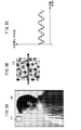
- FIG. 8A is a schematic explanatory diagram showing a rectangular area 112 outside the granularity adjustment area 102 (see FIG. 4B).
- FIG. 8B is a partially enlarged view of the rectangular area 112 shown in FIG. 8A.
- FIG. 8C is a graph showing a microscopic density profile along the arrow shown in FIG. 8B.
- an image having a relatively flat density is formed by forming a large number of dots of four colors (CMYK). Further, as shown in FIGS. 8B and 8C, the density is low at a part where no dot is formed, and the density is high at a part where a dot is formed. That is, a density profile that is macroscopically flat and microscopically fluctuates regularly around the average density shown by the broken line is obtained.
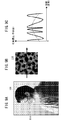
- FIG. 9A is a schematic explanatory diagram showing a rectangular area 114 in the granularity adjustment area 102 (see FIG. 4B).
- FIG. 9B is a partially enlarged view of the rectangular area 114 shown in FIG. 9A.
- FIG. 9C is a graph showing a microscopic density profile along the arrow shown in FIG. 9B.
- an image having a large density undulation is formed by forming a large number of dots of four colors (CMYK). Further, as shown in FIGS. 9B and 9C, microscopically, a density profile that regularly changes around a curved density trend shown by a broken line is obtained.
- the standard deviation calculator 54 calculates the standard deviation of the print density from the prediction results (microscopic density profiles) shown in FIGS. 8C and 9C.
- the index representing the amount of variation in print density is not limited to the standard deviation, and various statistical values such as maximum amplitude and variance can be applied.
- the visual correction unit 56 corrects the standard deviation acquired from the standard deviation calculation unit 54, thereby acquiring the granularity GR associated with the visibility (graininess) of the image.
- This association may be determined based on the result of sensory evaluation performed in advance, or may be a conversion formula based on a mathematical model.
- the granularity comparison unit 58 compares and evaluates the granularity GR calculated by the granularity calculation unit 46 and the target value Gt (step S7).
- the values calculated for the granularity GR are G1 to G7, respectively.
- the table selection unit 60 selects one color conversion table from the candidate table group (step S8).
- FIG. 10 is a schematic explanatory diagram showing the relationship between the granularity GR in the granularity adjustment region 102 and the set target value Gt when color conversion is performed using each candidate table.
- the granularity GR takes the largest value (G1).
- the value of the granularity GR gradually decreases as the usage amount of the K ink 22k is gradually decreased.
- the granularity GR takes the smallest value (G7).
- the table selection unit 60 may select a color conversion table corresponding to the value G5 closest to the target value Gt. Further, the target value Gt may be interpreted as an allowable upper limit value, and the table selection unit 60 may select a color conversion table corresponding to the closest value G6 that does not exceed the target value Gt.
- the table selection unit 60 may determine and determine comprehensively by appropriately weighting the evaluation result of the granularity GR for each region. .
- the color matching unit 50 converts the device color signal using the one color conversion table selected and determined by the color conversion table determination unit 48 (step S9).
- conversion may be performed for all the pixels in the image area 100, or conversion may be limited to the pixels in the granularity adjustment area 102.
- the color conversion apparatus 12 outputs the converted device color signal (CMYK signal data) to the image forming apparatus 14 side via the output interface 36 (step S10).
- the image forming apparatus 14 converts the supplied device color signal into a control signal used for controlling the ejection of the ink 22 by the recording head 20, and ejects a droplet of the ink 22 based on the control signal.
- An image (printed matter 28) is printed by attaching droplets of ink 22 to the surface of a medium (not shown) and forming a large number of dots on the medium.
- At least one granularity adjustment region 102 or 104 for adjusting the granularity GR of the image is extracted from the image region 100 represented by the input device color signal, and each extracted granularity adjustment region is extracted.
- the target value Gt of the granularity GR is set for 102 and 104, respectively, and the granularities G1 to G7 in the respective granularity adjustment regions 102 and 104 are calculated, so that they are closer to the target value Gt than before conversion (G4).
- the device color signals in the granularity adjustment regions 102 and 104 are converted to the above.
- FIGS. 11 and 12 The configuration of this printing system is basically the same as that of the first embodiment (see FIG. 1). However, in place of the color conversion device 12, color separation is performed to separate into device color signals having different color plate types. The difference is that the device 12A is provided.
- FIG. 11 is an electrical schematic block diagram of a plate separation apparatus 12A according to the second embodiment.
- the color separation device 12A lacks the components of the rasterization processing unit 38, the color conversion table determination unit 48, and the color matching conversion unit 50, as compared with the color conversion device 12 (see FIG. 2). Instead, the color separation device 12A separates the input device color signal into a device color signal having a different color plate type from the device color signal, and the color separation processing unit 200. And a separation table determining unit 202 (separation condition determining unit) that determines a separation table (separation condition information) to be used for the separation process.
- the separation condition information means various information for determining the separation condition.
- the color separation condition information includes, for example, the type and number of color plates of input and output signals, a color separation table (conversion LUT), coefficients of a conversion matrix, form / coefficients of conversion equations, learning model variables, and the like. The following description is based on the assumption that a separation table is used as the separation condition information.
- the color separation processing unit 200 separates an arbitrary color plate type (for example, RGB signal data) into CMYK signal data. Note that it is desirable that the device color signal after the color separation matches the type of device color signal used for control of the image forming apparatus 14 (CMYK in the example of FIG. 1).
- the separation table determination unit 202 determines one separation table from a plurality of separation tables.
- the color separation table determination unit 202 sets a K value of the color separation table to be created in advance, and a color separation table based on the K value set by the K value setting unit 204.
- the granularity GR calculated by the color separation table creation unit 206, the granularity calculation unit 46, and the target value Gt set by the target value setting unit 44 are compared and evaluated, and the suitability of the separation table is determined.
- a standard separation table 212 used for standard separation processing is recorded.
- the plate separation device 12A according to the second embodiment is configured as described above. Next, the operation of the plate separation apparatus 12A will be described with reference to the flowchart of FIG. For convenience of explanation, detailed description of steps for performing the same operation as in the first embodiment (see FIG. 3) is omitted.
- steps S11 to S14 the operation from the device color signal input operation to the operation for setting the target value Gt of the granularity GR is the same as that in steps S1 to S4 (see FIG. 3).
- the device color signal input in step S11 is a color plate (for example, RGB signal data) different from the color plate used for printing in the image forming apparatus 14.
- the granularity calculation unit 46 performs the separation in the granularity adjustment region 102 and the like when the color separation processing is performed using this standard color separation table.
- the granularity GR is calculated (step S16).
- the analysis image data creation unit 40 uses the device color signal for executing the color separation process and the color separation table to be evaluated to use the analysis image data (CMYK signal) for calculating the granularity GR. Data).
- the method of calculating the granularity GR in the granularity adjustment region 102 or the like may be the same as in the first embodiment.
- the table suitability determination unit 208 determines whether or not the granularity GR calculated by the granularity calculation unit 46 is sufficiently close to the target value Gt (step S17).
- one color conversion table is selected by performing relative evaluation on a plurality of color conversion tables (candidate tables).
- an allowable range for the target value Gt is determined in advance, and it is determined whether or not the calculated granularity GR is within the allowable range.
- the table suitability determination unit 208 supplies the value of the granularity GR and the target value Gt to the K value setting unit 204 together with the determination result. .
- the K value setting unit 204 determines the magnitude relationship between the granularity GR and the target value Gt (step S18).
- the K value setting unit 204 subtracts a predetermined value from the K value in the current color separation table (initial color separation table 212) (step S19).
- the K value setting unit 204 adds a predetermined value to the K value in the current separation table (initial separation table 212 for the first time) ( Step S20).
- the color separation table creating unit 206 creates a new color separation table based on the K value newly set by the K value setting unit 204 (step S21). In this case, various known creation algorithms for the separation table may be applied. Thereafter, the process returns to step S16, and thereafter, steps S16 to S21 are sequentially repeated until the table suitability determination unit 208 determines that the granularity GR is sufficiently close to the target value Gt.
- the color separation table determination unit 202 determines the current color separation table as a color separation table to be subjected to the color separation processing (step). S22). Then, the color separation processing unit 200 separates the input RGB signal data into CMYK signal data (step S23).
- the color conversion device 12 outputs the device color signal after separation (CMYK signal data) to the image forming device 14 side via the output interface 36 (step S24).
- one separation table is determined from a plurality of separation tables (separation condition information) so that the calculated granularity GR is closer to the target value Gt than other separation conditions. Even if the plate separation process is performed, the same effect can be obtained.
- color conversion processing is performed using a color conversion table (LUT).
- LUT color conversion table
- the processing mode is not limited to, for example, a learning model such as a neural network or the like as well as a conversion matrix and a conversion formula. May be.
- the print color predicted by the print density prediction unit 52 is not limited to the print density, and may be various colorimetric values.
- colorimetric values not only tristimulus values XYZ and values L * a * b * on a uniform color space, but also distributions of optical physical properties with respect to wavelength, such as spectral radiation distribution (spectral distribution), spectral sensitivity distribution, Spectral reflectance or spectral transmittance may be used.
- CMYK four color plates
- the design can be changed to any color plate type and plate number without being limited thereto.
- a standard ink of CMYK may be combined with an optional ink such as light colors such as LC and LM and W (white).
- the image forming apparatus 14 is not limited to an ink jet printer, and it is needless to say that the present invention can be applied to any system that forms dots by attaching a coloring material on a medium.
Landscapes
- Engineering & Computer Science (AREA)
- Multimedia (AREA)
- Signal Processing (AREA)
- Facsimile Image Signal Circuits (AREA)
- Color Image Communication Systems (AREA)
- Image Processing (AREA)
Abstract
La présente invention se rapporte à un dispositif de conversion de couleurs, à un procédé de conversion de couleurs, à un programme et à un dispositif de séparation de couleurs. Une valeur cible (Gt) de granularité (GR) est établie par rapport à chacune des zones d'ajustement de la granularité (102, 104) où la granularité d'une image doit être ajustée. Des signaux de couleur du dispositif dans chacune des zones d'ajustement de la granularité (102, 104) sont convertis de telle sorte que la granularité calculée (GR) soit plus proche de la valeur cible (Gt) par comparaison à la granularité obtenue avant conversion, et que la granularité calculée se trouve à l'intérieur d'une plage isochromatique (R) dans un espace de couleurs indépendant du dispositif.
Priority Applications (2)
| Application Number | Priority Date | Filing Date | Title |
|---|---|---|---|
| JP2013507206A JP5604000B2 (ja) | 2011-03-28 | 2012-01-05 | 色変換装置、色変換方法、プログラム及び分版装置 |
| US14/039,508 US8848265B2 (en) | 2011-03-28 | 2013-09-27 | Color conversion device, color conversion method, recording medium, and color separation device |
Applications Claiming Priority (2)
| Application Number | Priority Date | Filing Date | Title |
|---|---|---|---|
| JP2011-069268 | 2011-03-28 | ||
| JP2011069268 | 2011-03-28 |
Related Child Applications (1)
| Application Number | Title | Priority Date | Filing Date |
|---|---|---|---|
| US14/039,508 Continuation US8848265B2 (en) | 2011-03-28 | 2013-09-27 | Color conversion device, color conversion method, recording medium, and color separation device |
Publications (1)
| Publication Number | Publication Date |
|---|---|
| WO2012132481A1 true WO2012132481A1 (fr) | 2012-10-04 |
Family
ID=46930249
Family Applications (1)
| Application Number | Title | Priority Date | Filing Date |
|---|---|---|---|
| PCT/JP2012/050049 Ceased WO2012132481A1 (fr) | 2011-03-28 | 2012-01-05 | Dispositif de conversion de couleurs, procédé de conversion de couleurs, programme et dispositif de séparation de couleurs |
Country Status (3)
| Country | Link |
|---|---|
| US (1) | US8848265B2 (fr) |
| JP (1) | JP5604000B2 (fr) |
| WO (1) | WO2012132481A1 (fr) |
Cited By (1)
| Publication number | Priority date | Publication date | Assignee | Title |
|---|---|---|---|---|
| JP2021180377A (ja) * | 2020-05-12 | 2021-11-18 | キヤノン株式会社 | 画像処理装置、その制御方法及びプログラム |
Families Citing this family (4)
| Publication number | Priority date | Publication date | Assignee | Title |
|---|---|---|---|---|
| JP5918176B2 (ja) * | 2013-07-26 | 2016-05-18 | 京セラドキュメントソリューションズ株式会社 | 画像形成装置 |
| JP5856594B2 (ja) * | 2013-08-30 | 2016-02-10 | 富士フイルム株式会社 | 色分解装置、色分解方法および色分解プログラム |
| JP2018069593A (ja) * | 2016-10-31 | 2018-05-10 | 京セラドキュメントソリューションズ株式会社 | モノクロ画像形成装置 |
| CN116704092B (zh) * | 2023-08-09 | 2023-12-22 | 广州市乐淘动漫设计有限公司 | 一种动漫场景实时渲染系统 |
Citations (4)
| Publication number | Priority date | Publication date | Assignee | Title |
|---|---|---|---|---|
| JP2002374425A (ja) * | 2001-06-13 | 2002-12-26 | Sharp Corp | 画像処理方法、画像処理プログラムおよび画像処理装置並びに画像処理装置を備えた画像形成装置 |
| JP2005094085A (ja) * | 2003-09-12 | 2005-04-07 | Ricoh Co Ltd | 画像処理装置および色変換調整方法 |
| JP2006264144A (ja) * | 2005-03-24 | 2006-10-05 | Seiko Epson Corp | 印刷制御装置、印刷制御方法および印刷制御プログラム |
| JP2008118191A (ja) * | 2006-10-31 | 2008-05-22 | Canon Inc | 画像処理装置及びその画像処理方法 |
Family Cites Families (8)
| Publication number | Priority date | Publication date | Assignee | Title |
|---|---|---|---|---|
| US5374954A (en) * | 1990-10-11 | 1994-12-20 | Harry E. Mowry | Video system for producing video image simulating the appearance of motion picture or other photographic film |
| US6207360B1 (en) * | 1997-05-12 | 2001-03-27 | Fuji Photo Film Co., Ltd. | Method for image formation and apparatus for development processing |
| JP3767189B2 (ja) | 1998-08-27 | 2006-04-19 | 富士ゼロックス株式会社 | カラー画像処理方法および装置 |
| US7136542B2 (en) * | 2002-01-30 | 2006-11-14 | Fuji Photo Film Co., Ltd. | Image retrieval method |
| US7432986B2 (en) * | 2005-02-16 | 2008-10-07 | Lsi Corporation | Method and apparatus for masking of video artifacts and/or insertion of film grain in a video decoder |
| JP4749884B2 (ja) | 2005-03-07 | 2011-08-17 | 富士フイルム株式会社 | 顔判別装置の学習方法、顔判別方法および装置並びにプログラム |
| JP4880292B2 (ja) | 2005-11-24 | 2012-02-22 | 富士フイルム株式会社 | 画像処理方法および画像処理プログラムならびに画像処理装置 |
| JP2009241609A (ja) | 2009-07-27 | 2009-10-22 | Seiko Epson Corp | 印刷制御装置、印刷装置、および印刷制御方法 |
-
2012
- 2012-01-05 WO PCT/JP2012/050049 patent/WO2012132481A1/fr not_active Ceased
- 2012-01-05 JP JP2013507206A patent/JP5604000B2/ja not_active Expired - Fee Related
-
2013
- 2013-09-27 US US14/039,508 patent/US8848265B2/en not_active Expired - Fee Related
Patent Citations (4)
| Publication number | Priority date | Publication date | Assignee | Title |
|---|---|---|---|---|
| JP2002374425A (ja) * | 2001-06-13 | 2002-12-26 | Sharp Corp | 画像処理方法、画像処理プログラムおよび画像処理装置並びに画像処理装置を備えた画像形成装置 |
| JP2005094085A (ja) * | 2003-09-12 | 2005-04-07 | Ricoh Co Ltd | 画像処理装置および色変換調整方法 |
| JP2006264144A (ja) * | 2005-03-24 | 2006-10-05 | Seiko Epson Corp | 印刷制御装置、印刷制御方法および印刷制御プログラム |
| JP2008118191A (ja) * | 2006-10-31 | 2008-05-22 | Canon Inc | 画像処理装置及びその画像処理方法 |
Cited By (2)
| Publication number | Priority date | Publication date | Assignee | Title |
|---|---|---|---|---|
| JP2021180377A (ja) * | 2020-05-12 | 2021-11-18 | キヤノン株式会社 | 画像処理装置、その制御方法及びプログラム |
| JP7490447B2 (ja) | 2020-05-12 | 2024-05-27 | キヤノン株式会社 | 画像処理装置、その制御方法及びプログラム |
Also Published As
| Publication number | Publication date |
|---|---|
| JPWO2012132481A1 (ja) | 2014-07-24 |
| JP5604000B2 (ja) | 2014-10-08 |
| US20140029060A1 (en) | 2014-01-30 |
| US8848265B2 (en) | 2014-09-30 |
Similar Documents
| Publication | Publication Date | Title |
|---|---|---|
| US8792136B2 (en) | Processing condition selecting apparatus, processing condition selecting method, and storage medium | |
| US9066054B2 (en) | Image indexed rendering of images for tuning images from single or multiple print engines | |
| JP5014475B2 (ja) | 画像処理装置および画像処理方法 | |
| US7365878B2 (en) | Color adjustment apparatus, print control apparatus, color adjustment method, and color adjustment program product | |
| JP5604000B2 (ja) | 色変換装置、色変換方法、プログラム及び分版装置 | |
| JP5634154B2 (ja) | 画像処理装置および画像処理方法 | |
| JP2005348053A (ja) | 色変換を行う装置、印刷制御装置、方法およびプログラム、色変換データを作成する装置、方法およびプログラム、並びに、色変換データを記録した記録媒体 | |
| JP6095623B2 (ja) | 色変換方法及び装置、プログラム、並びに色変換システム | |
| US8773741B2 (en) | Color reproduction predicting apparatus, color reproduction predicting method, and recording medium | |
| US10511744B2 (en) | Image processing apparatus and method that suppress difference in colors printed in forward and backward scans, and storage medium | |
| US8462385B2 (en) | Color matching for color management systems | |
| JP5769465B2 (ja) | 色変換装置、色変換方法及びプログラム | |
| US9767397B2 (en) | Color separation condition determining apparatus, method and non-transitory storage medium | |
| CN102673194B (zh) | 打印控制装置以及打印控制方法 | |
| JP5685306B2 (ja) | 色変換装置、色変換方法及びプログラム | |
| JP5606150B2 (ja) | 画像処理装置及び画像処理方法 | |
| US8478031B2 (en) | Image processing using colored colorant amounts and colorless colorant amounts | |
| JP6151673B2 (ja) | 印刷色予測方法及び装置、プロファイル生成方法及び装置、並びにプログラム | |
| JP7362365B2 (ja) | 画像処理装置、画像処理方法及びプログラム | |
| US11909938B2 (en) | Printing method including gradation region ink amount calculation step | |
| JP2024088570A (ja) | 画像処理装置、画像処理方法およびプログラム | |
| JP2011024054A (ja) | 画像処理装置および画像処理方法 | |
| JP2013135243A (ja) | 印刷制御装置、プログラム、及び印刷装置 |
Legal Events
| Date | Code | Title | Description |
|---|---|---|---|
| 121 | Ep: the epo has been informed by wipo that ep was designated in this application |
Ref document number: 12764791 Country of ref document: EP Kind code of ref document: A1 |
|
| ENP | Entry into the national phase |
Ref document number: 2013507206 Country of ref document: JP Kind code of ref document: A |
|
| NENP | Non-entry into the national phase |
Ref country code: DE |
|
| 122 | Ep: pct application non-entry in european phase |
Ref document number: 12764791 Country of ref document: EP Kind code of ref document: A1 |