WO2012132542A1 - Dispositif de commande pour boîte de vitesses automatique - Google Patents
Dispositif de commande pour boîte de vitesses automatique Download PDFInfo
- Publication number
- WO2012132542A1 WO2012132542A1 PCT/JP2012/052373 JP2012052373W WO2012132542A1 WO 2012132542 A1 WO2012132542 A1 WO 2012132542A1 JP 2012052373 W JP2012052373 W JP 2012052373W WO 2012132542 A1 WO2012132542 A1 WO 2012132542A1
- Authority
- WO
- WIPO (PCT)
- Prior art keywords
- range
- oil
- select lever
- signal
- range signal
- Prior art date
- Legal status (The legal status is an assumption and is not a legal conclusion. Google has not performed a legal analysis and makes no representation as to the accuracy of the status listed.)
- Ceased
Links
Images
Classifications
-
- F—MECHANICAL ENGINEERING; LIGHTING; HEATING; WEAPONS; BLASTING
- F16—ENGINEERING ELEMENTS AND UNITS; GENERAL MEASURES FOR PRODUCING AND MAINTAINING EFFECTIVE FUNCTIONING OF MACHINES OR INSTALLATIONS; THERMAL INSULATION IN GENERAL
- F16H—GEARING
- F16H61/00—Control functions within control units of change-speed- or reversing-gearings for conveying rotary motion ; Control of exclusively fluid gearing, friction gearing, gearings with endless flexible members or other particular types of gearing
- F16H61/12—Detecting malfunction or potential malfunction, e.g. fail safe ; Circumventing or fixing failures
-
- F—MECHANICAL ENGINEERING; LIGHTING; HEATING; WEAPONS; BLASTING
- F16—ENGINEERING ELEMENTS AND UNITS; GENERAL MEASURES FOR PRODUCING AND MAINTAINING EFFECTIVE FUNCTIONING OF MACHINES OR INSTALLATIONS; THERMAL INSULATION IN GENERAL
- F16H—GEARING
- F16H61/00—Control functions within control units of change-speed- or reversing-gearings for conveying rotary motion ; Control of exclusively fluid gearing, friction gearing, gearings with endless flexible members or other particular types of gearing
- F16H61/18—Preventing unintentional or unsafe shift, e.g. preventing manual shift from highest gear to reverse gear
-
- F—MECHANICAL ENGINEERING; LIGHTING; HEATING; WEAPONS; BLASTING
- F16—ENGINEERING ELEMENTS AND UNITS; GENERAL MEASURES FOR PRODUCING AND MAINTAINING EFFECTIVE FUNCTIONING OF MACHINES OR INSTALLATIONS; THERMAL INSULATION IN GENERAL
- F16H—GEARING
- F16H61/00—Control functions within control units of change-speed- or reversing-gearings for conveying rotary motion ; Control of exclusively fluid gearing, friction gearing, gearings with endless flexible members or other particular types of gearing
- F16H61/12—Detecting malfunction or potential malfunction, e.g. fail safe ; Circumventing or fixing failures
- F16H2061/1256—Detecting malfunction or potential malfunction, e.g. fail safe ; Circumventing or fixing failures characterised by the parts or units where malfunctioning was assumed or detected
- F16H2061/1284—Detecting malfunction or potential malfunction, e.g. fail safe ; Circumventing or fixing failures characterised by the parts or units where malfunctioning was assumed or detected the failing part is a sensor
-
- F—MECHANICAL ENGINEERING; LIGHTING; HEATING; WEAPONS; BLASTING
- F16—ENGINEERING ELEMENTS AND UNITS; GENERAL MEASURES FOR PRODUCING AND MAINTAINING EFFECTIVE FUNCTIONING OF MACHINES OR INSTALLATIONS; THERMAL INSULATION IN GENERAL
- F16H—GEARING
- F16H61/00—Control functions within control units of change-speed- or reversing-gearings for conveying rotary motion ; Control of exclusively fluid gearing, friction gearing, gearings with endless flexible members or other particular types of gearing
- F16H61/16—Inhibiting or initiating shift during unfavourable conditions , e.g. preventing forward-reverse shift at high vehicle speed, preventing engine overspeed
- F16H2061/168—Forced shifts into neutral for safety reasons, e.g. in case of transmission failure or emergency braking
-
- F—MECHANICAL ENGINEERING; LIGHTING; HEATING; WEAPONS; BLASTING
- F16—ENGINEERING ELEMENTS AND UNITS; GENERAL MEASURES FOR PRODUCING AND MAINTAINING EFFECTIVE FUNCTIONING OF MACHINES OR INSTALLATIONS; THERMAL INSULATION IN GENERAL
- F16H—GEARING
- F16H59/00—Control inputs to control units of change-speed- or reversing-gearings for conveying rotary motion
- F16H59/02—Selector apparatus
- F16H59/04—Ratio selector apparatus
- F16H59/044—Ratio selector apparatus consisting of electrical switches or sensors
Definitions
- the present invention relates to a control device for an automatic transmission.
- JP 6-147316A discloses that a shift position is processed as an N range when the select lever is between an N range which is a non-traveling range and a D range which is a traveling range.
- the inhibitor switch when the inhibitor switch outputs a signal corresponding to an intermediate position between the D range signal and the N range signal due to, for example, a failure during driving, the shift position is processed as the N range. There is a problem that the driving force generated at the power source is not transmitted, and the vehicle decelerates during traveling against the driver's intention.
- the present invention has been invented to solve such a problem, and even when the inhibitor switch outputs a signal corresponding to an intermediate position between the D range signal and the N range signal during traveling, the drive source
- the purpose is to transmit the driving force generated by the vehicle and suppress deceleration unintended by the driver during traveling.
- a control device for an automatic transmission includes a friction engagement element that transmits rotation when oil is supplied and fastened, and includes a frictional fastening element that blocks transmission of rotation when oil is discharged and released. It is the control apparatus of the automatic transmission which controls a transmission.
- the control device for the automatic transmission is mechanically connected to a select lever, and supplies a first hydraulic pressure control unit that supplies and discharges oil to and from the frictional engagement element in accordance with the operation position of the select lever, and a range in accordance with the operation position of the select lever.
- a range signal output unit that outputs a signal
- a second hydraulic control unit that is arranged in series with the first hydraulic control unit and that supplies and discharges oil to and from the frictional engagement element according to the range signal, and determines whether the vehicle is stopped
- the second hydraulic control unit can supply oil to the frictional engagement element when the signal corresponding to the intermediate position between the travel range and the non-travel range is output by the range signal output unit and the vehicle is traveling. An oil passage is formed.
- the frictional engagement element is immediately released without releasing the frictional engagement element. Since it can be fastened, deceleration that is not intended by the driver during traveling can be suppressed.
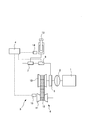
- FIG. 1 is a schematic configuration diagram of a vehicle having a control device for an automatic transmission according to an embodiment of the present invention.
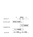
- FIG. 2 is a diagram showing a region where the manual valve hydraulic pressure can be generated by operating the select lever and a conduction region of the inhibitor switch.
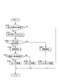
- FIG. 3 is a flowchart for explaining the signal processing control of the inhibitor switch in the embodiment of the present invention.
- FIG. 1 is a schematic configuration diagram of a vehicle having a control device for an automatic transmission according to the present embodiment.
- the vehicle includes an engine 1, a torque converter 2, a continuously variable transmission 3, and a controller 4.
- the continuously variable transmission 3 includes a forward / reverse switching mechanism 5, a variator 6, a manual valve 7, and a solenoid 8.
- the forward / reverse switching mechanism 5 switches the engagement state of the forward clutch or the reverse clutch by the oil supplied and discharged via the manual valve 7 and the solenoid 8.
- the variator 6 includes a primary pulley 10, a secondary pulley 11, and a belt 12 that is wound around the primary pulley 10 and the secondary pulley 11.
- the rotation generated in the engine 1 is transmitted in the order of the torque converter 2, the continuously variable transmission 3, and the drive wheels (not shown), and the vehicle travels.
- the manual valve 7 is mechanically connected to the select lever 13, forms an oil passage based on the operation of the select lever 13, and supplies / discharges oil to / from the forward / reverse switching mechanism 5.
- the manual valve 7 supplies oil to the forward / reverse switching mechanism 5 when the select lever 13 is in the travel range (D range or R range) and at an intermediate position between the travel range and the non-travel range (N range or P range). Form an oil passage.
- the manual valve 7 forms an oil passage so that oil is discharged from the forward / reverse switching mechanism 5 when the select lever 13 is in the non-traveling range.
- the solenoid 8 forms an oil passage based on a signal output from the inhibitor switch 14 and supplies / discharges oil to / from the forward / reverse switching mechanism 5.
- the solenoid 8 is arranged in series with the manual valve 7.
- the arrangement in series means that when oil is supplied to the forward / reverse switching mechanism 5, the manual valve 7 and the solenoid 8 are arranged along the oil flow direction. Therefore, when the oil passage is formed so that the manual valve 7 supplies oil to the forward / reverse switching mechanism 5 and the solenoid 8 forms the oil path so as to supply oil to the forward / reverse switching mechanism 5, Oil is supplied to the forward / reverse switching mechanism 5 through the manual valve 7 and the solenoid 8.
- the inhibitor switch 14 outputs a range signal according to the position of the select lever 13.
- the inhibitor switch 14 transmits a D range signal when the select lever 13 is detented to a position where the select lever 13 is in the D range.
- the inhibitor switch 14 is used when the select lever 13 is at an intermediate position between the travel range and the non-travel range adjacent to the travel range, that is, between the detent position of the travel range and the non-travel range. Outputs a running range signal and a non-running range signal as signals corresponding to the intermediate position. As an example, the inhibitor switch 14 outputs a D range signal and an N range signal when the select lever 13 is at an intermediate position between the D range and the N range adjacent to the D range.
- the inhibitor switch 14 outputs a signal corresponding to the intermediate position even when the contact for outputting each range signal is short-circuited.
- the contact of the N range is short-circuited.
- the controller 4 includes a CPU, a ROM, a RAM, and the like.
- the function of the continuously variable transmission 3 is exhibited by the CPU reading the program stored in the ROM.
- the controller 4 controls the solenoid 8 on the basis of the signal from the inhibitor switch 14 and the signal from the vehicle speed sensor 15, and supplies / discharges oil to / from the forward / reverse switching mechanism 5.
- FIG. 2 is a diagram showing a region where the hydraulic pressure can be generated by the manual valve 7 by the operation of the select lever 13 and a conduction region of the inhibitor switch 14.
- the manual valve 7 When the manual valve 7 is in the region where the hydraulic pressure can be generated, the manual valve 7 forms an oil passage so as to supply oil to the forward / reverse switching mechanism 5.
- the inhibitor switch 14 outputs a signal corresponding to the conduction region in each conduction region.
- the manual valve 7 forms an oil passage so as to discharge oil from the forward clutch.
- the inhibitor switch 14 outputs only the N range signal, and the solenoid 8 forms an oil passage so as to discharge oil from the forward clutch.
- the manual valve 7 moves forward.
- An oil passage is formed so as to supply oil to the clutch.
- the manual valve 7 gradually opens as the select lever 13 approaches the detent position of the D range, and the amount of oil that can be supplied to the forward clutch per unit time increases.
- the inhibitor switch 14 outputs an N range signal and a D range signal.
- the controller 4 processes the signal from the inhibitor switch 14 as an N range signal, and the solenoid 8 discharges oil from the forward clutch. An oil passage is formed. Therefore, no oil is supplied to the forward clutch, and the forward clutch is released.
- the inhibitor switch 14 When the select lever 13 reaches the detent position of the D range, the inhibitor switch 14 outputs only the D range signal, and the solenoid 8 forms an oil passage so that oil is gradually supplied to the forward clutch. As a result, oil is gradually supplied to the forward clutch, and the forward clutch is fastened.
- step S100 the controller 4 determines whether or not a signal corresponding to the intermediate position is received from the inhibitor switch 14. Specifically, the controller 4 determines whether or not two signals of a travel range signal and a non-travel range signal adjacent to the travel range are received.
- the travel range signal will be described as a D range signal and the non-travel range signal as an N range signal, but the same control is performed when the travel range signal is an R range signal. If the controller 4 has received two signals, the process proceeds to step S101. If either signal or neither signal has been received, the controller 4 ends this control.
- step S101 the controller 4 increments a timer indicating that two signals are received.
- the controller 4 adds “1” to the previous value.
- the initial value of the timer is “0”.
- step S102 the controller 4 compares the timer value with a predetermined time. Then, the controller 4 proceeds to step S103 when the timer value is smaller than the predetermined time, and proceeds to step S107 when the timer value exceeds the predetermined time.
- the predetermined time is a time during which it is possible to determine that the inhibitor switch 14 or the select lever 13 is abnormal, and is set in advance. When the inhibitor switch 14 or the select lever 13 is abnormal, it means that the two signals of the travel range signal and the non-travel range signal are continuously output for a longer time than normal.
- step S103 the controller 4 detects the vehicle speed by the vehicle speed sensor 15.
- step S104 the controller 4 compares the vehicle speed with a predetermined vehicle speed. Then, the controller 4 determines that the vehicle is traveling when the vehicle speed is higher than the predetermined vehicle speed, and proceeds to step S105, and determines that the vehicle is stopped when the vehicle speed is equal to or lower than the predetermined vehicle speed. Proceed to step S106.
- the predetermined vehicle speed is a vehicle speed capable of determining whether or not the vehicle is stopped.
- step S105 the controller 4 processes the signal of the inhibitor switch 14 as a D range signal.
- the controller 4 uses the signal of the inhibitor switch 14 as the D range signal. To process.
- this processing is performed when the N-range contact is short-circuited while traveling in the D range and the N-range signal is output by the inhibitor switch 14 in addition to the D-range signal, This is executed when the elbow or the like hits and the select lever 13 is held at an intermediate position between the D range and the N range.
- step S106 the controller 4 processes the signal of the inhibitor switch 14 as an N range signal.
- the controller 4 sends the signal from the inhibitor switch 14 to the N-range signal. Process as.
- the solenoid 8 forms an oil passage so as to discharge oil from the forward clutch, and the forward clutch is released.
- step S107 the controller 4 notifies the driver of the abnormality.
- the controller 4 notifies the driver of the abnormality by turning on or blinking a warning lamp, for example.
- a warning lamp for example.
- step S108 the controller 4 performs fail-safe control. Specifically, the controller 4 processes the signal of the inhibitor switch 14 as a D range signal. As a result, the solenoid 8 forms an oil passage so as to supply oil to the forward clutch, so that the vehicle can travel. Even when fail-safe control is being performed, when the vehicle is stopped, if the select lever 13 is operated to the non-traveling range, the manual valve 7 is switched forward and backward in conjunction with the operation of the select lever 13. An oil passage is formed so that oil is discharged from the mechanism 5, and the oil is discharged by the manual valve 7. Accordingly, the forward clutch or the reverse brake is released, so that the rotation of the engine 1 is not transmitted to the drive wheels, and the vehicle can be stopped.
- the solenoid 8 forms an oil passage so that oil is supplied to the forward / reverse switching mechanism 5.
- an abnormality occurs in the select lever 13 or the inhibitor switch 14, and the inhibitor switch 14 outputs a signal corresponding to an intermediate position between the traveling range and the non-driving range, that is, the traveling range signal and the non-driving range signal.
- oil can be supplied to the forward / reverse switching mechanism 5 and the forward clutch or the reverse brake can be fastened, so that deceleration that is not intended by the driver can be suppressed and traveling can be continued.
- the solenoid moves the forward / reverse switching mechanism by the solenoid.
- the oil passage is formed so as to supply oil, oil cannot be supplied to the forward / reverse switching mechanism.
- the mismatch is resolved and oil is supplied from the manual valve to the forward / reverse switching mechanism.
- the select lever 13 When the select lever 13 is changed from the non-traveling range position to the traveling range position, the timing at which the inhibitor switch 14 outputs a traveling range signal and the timing at which the oil path from the manual valve 7 to the forward / reverse switching mechanism 5 is formed. Simultaneously is difficult due to manufacturing variations.
- the select lever 13 in order to form an oil passage so that oil can be reliably supplied from the manual valve 7 to the forward / reverse switching mechanism 5 when the select lever 13 is in the travel range position, the select lever 13 is not connected to the travel range.
- the manual valve 7 forms an oil passage to the forward / reverse switching mechanism 5 at an intermediate position with respect to the travel range.
- the solenoid 8 moves the oil forward and backward when the vehicle is stopped.
- An oil passage is formed so as to be discharged from the switching mechanism 5.
- the selector lever 13 or the inhibitor switch 14 When the time for which the inhibitor switch 14 outputs the traveling range signal and the non-driving range signal is longer than the predetermined time, the selector lever 13 or the inhibitor switch 14 is informed that an abnormality has occurred. Thereby, when the select lever 13 is in an intermediate position between the travel range and the non-travel range, it is possible to prompt the user to change the select lever 13 to an appropriate position. Further, when the inhibitor switch 14 breaks down and the traveling range signal and the non-driving range signal are output, the driver can be informed that repair is necessary.
- the continuously variable transmission is described as the automatic transmission.
- the present invention is not limited to this, and a stepped transmission may be used.
- the stepped transmission may be controlled so as to achieve a predetermined shift speed.
- the inhibitor switch 14 outputs a travel range signal and a non-travel range signal as signals corresponding to the intermediate position, but is not limited thereto, and may output a zero signal or another signal.
- the zero signal means a state in which no range signal is output.
Landscapes
- Engineering & Computer Science (AREA)
- General Engineering & Computer Science (AREA)
- Mechanical Engineering (AREA)
- Control Of Transmission Device (AREA)
Abstract
Le dispositif de l'invention est équipé : d'une première unité de commande hydraulique qui est mécaniquement raccordée à un levier de sélection, et qui alimente en huile un élément de fixation à friction selon une position de manœuvre du levier de sélection; et d'une seconde unité de commande hydraulique qui alimente en huile un élément de fixation à friction selon un signal de plage émis en sortie par une unité d'émission en sortie de signal de plage. La seconde unité de commande hydraulique forme un passage d'huile qui alimente en huile l'élément de fixation à friction, lorsqu'est émis en sortie par l'unité d'émission en sortie de signal de plage un signal correspondant à une position intermédiaire entre une plage de déplacement et une plage de non-déplacement, et lorsque le véhicule se déplace.
Applications Claiming Priority (2)
| Application Number | Priority Date | Filing Date | Title |
|---|---|---|---|
| JP2011074896 | 2011-03-30 | ||
| JP2011-074896 | 2011-03-30 |
Publications (1)
| Publication Number | Publication Date |
|---|---|
| WO2012132542A1 true WO2012132542A1 (fr) | 2012-10-04 |
Family
ID=46930309
Family Applications (1)
| Application Number | Title | Priority Date | Filing Date |
|---|---|---|---|
| PCT/JP2012/052373 Ceased WO2012132542A1 (fr) | 2011-03-30 | 2012-02-02 | Dispositif de commande pour boîte de vitesses automatique |
Country Status (1)
| Country | Link |
|---|---|
| WO (1) | WO2012132542A1 (fr) |
Citations (6)
| Publication number | Priority date | Publication date | Assignee | Title |
|---|---|---|---|---|
| JPS6487946A (en) * | 1987-09-29 | 1989-04-03 | Aisin Seiki | Shift lever position detecting device |
| JPH01250647A (ja) * | 1988-03-31 | 1989-10-05 | Fuji Heavy Ind Ltd | シフトレバー位置信号の判定方法 |
| JPH0893899A (ja) * | 1994-09-20 | 1996-04-12 | Hino Motors Ltd | 自動車の制御装置 |
| JPH11190423A (ja) * | 1997-12-26 | 1999-07-13 | Toyota Autom Loom Works Ltd | 車両の安全装置 |
| JP2001108091A (ja) * | 1999-10-08 | 2001-04-20 | Toyota Motor Corp | 自動変速機のフェールセーフ装置 |
| JP2004251309A (ja) * | 2003-02-18 | 2004-09-09 | Nissan Motor Co Ltd | シフトバイワイヤ式自動変速機のレンジ選択装置 |
-
2012
- 2012-02-02 WO PCT/JP2012/052373 patent/WO2012132542A1/fr not_active Ceased
Patent Citations (6)
| Publication number | Priority date | Publication date | Assignee | Title |
|---|---|---|---|---|
| JPS6487946A (en) * | 1987-09-29 | 1989-04-03 | Aisin Seiki | Shift lever position detecting device |
| JPH01250647A (ja) * | 1988-03-31 | 1989-10-05 | Fuji Heavy Ind Ltd | シフトレバー位置信号の判定方法 |
| JPH0893899A (ja) * | 1994-09-20 | 1996-04-12 | Hino Motors Ltd | 自動車の制御装置 |
| JPH11190423A (ja) * | 1997-12-26 | 1999-07-13 | Toyota Autom Loom Works Ltd | 車両の安全装置 |
| JP2001108091A (ja) * | 1999-10-08 | 2001-04-20 | Toyota Motor Corp | 自動変速機のフェールセーフ装置 |
| JP2004251309A (ja) * | 2003-02-18 | 2004-09-09 | Nissan Motor Co Ltd | シフトバイワイヤ式自動変速機のレンジ選択装置 |
Similar Documents
| Publication | Publication Date | Title |
|---|---|---|
| KR101787249B1 (ko) | 동력 전달 장치 | |
| KR101472246B1 (ko) | 자동 변속기의 제어 장치 | |
| CN103161593A (zh) | 车辆控制装置及车辆的控制方法 | |
| JPWO2016152329A1 (ja) | 車両用自動変速機のフェール判定装置及び車両用自動変速機の制御装置 | |
| US20120283901A1 (en) | Control system for hybrid vehicle | |
| JP6922173B2 (ja) | 無段変速機の制御方法及び制御装置 | |
| JP6554545B2 (ja) | ベルト無段変速機及びその故障判断方法 | |
| JP6554546B2 (ja) | ベルト無段変速機及びその故障判断方法 | |
| JP6545891B2 (ja) | 自動変速機の異常検出装置 | |
| WO2018206572A1 (fr) | Appareil et procédé de commande de mode de sécurité pour transmission à double embrayage dans un véhicule | |
| WO2014157085A1 (fr) | Transmission à variation continue et procédé de commande | |
| WO2012132542A1 (fr) | Dispositif de commande pour boîte de vitesses automatique | |
| JP6885409B2 (ja) | 無段変速機の制御方法、及び、無段変速システム | |
| JP2004116605A (ja) | 自動変速機 | |
| JP5669941B2 (ja) | 車両の制御装置 | |
| JP6152494B1 (ja) | 自動変速機の制御装置及び自動変速機の制御方法 | |
| JP6543540B2 (ja) | ベルト無段変速機及びその故障判断方法 | |
| JP5118859B2 (ja) | 自動変速機の制御装置 | |
| JP5810633B2 (ja) | 車両の制御装置 | |
| JP5476525B2 (ja) | 無段変速機 | |
| JP6718022B2 (ja) | 車両の制御装置及び車両の制御方法 | |
| JP6725234B2 (ja) | 車両の制御装置、及び車両の制御方法 | |
| JP6694286B2 (ja) | 車両の制御装置、及び車両の制御方法 | |
| JP6670620B2 (ja) | 車両用無段変速機の異常判定装置及び異常時対応装置 | |
| WO2013132899A1 (fr) | Appareil de commande de changement de vitesse et procédé de commande de changement de vitesse pour une transmission à variation continue |
Legal Events
| Date | Code | Title | Description |
|---|---|---|---|
| 121 | Ep: the epo has been informed by wipo that ep was designated in this application |
Ref document number: 12764320 Country of ref document: EP Kind code of ref document: A1 |
|
| NENP | Non-entry into the national phase |
Ref country code: DE |
|
| 122 | Ep: pct application non-entry in european phase |
Ref document number: 12764320 Country of ref document: EP Kind code of ref document: A1 |
|
| NENP | Non-entry into the national phase |
Ref country code: JP |