WO2012133233A1 - 円筒形電池及び電池用電極構造 - Google Patents
円筒形電池及び電池用電極構造 Download PDFInfo
- Publication number
- WO2012133233A1 WO2012133233A1 PCT/JP2012/057616 JP2012057616W WO2012133233A1 WO 2012133233 A1 WO2012133233 A1 WO 2012133233A1 JP 2012057616 W JP2012057616 W JP 2012057616W WO 2012133233 A1 WO2012133233 A1 WO 2012133233A1
- Authority
- WO
- WIPO (PCT)
- Prior art keywords
- electrode plate
- positive electrode
- negative electrode
- group
- battery
- Prior art date
- Legal status (The legal status is an assumption and is not a legal conclusion. Google has not performed a legal analysis and makes no representation as to the accuracy of the status listed.)
- Ceased
Links
Images


Classifications
-
- H—ELECTRICITY
- H01—ELECTRIC ELEMENTS
- H01M—PROCESSES OR MEANS, e.g. BATTERIES, FOR THE DIRECT CONVERSION OF CHEMICAL ENERGY INTO ELECTRICAL ENERGY
- H01M10/00—Secondary cells; Manufacture thereof
- H01M10/04—Construction or manufacture in general
- H01M10/0431—Cells with wound or folded electrodes
-
- H—ELECTRICITY
- H01—ELECTRIC ELEMENTS
- H01M—PROCESSES OR MEANS, e.g. BATTERIES, FOR THE DIRECT CONVERSION OF CHEMICAL ENERGY INTO ELECTRICAL ENERGY
- H01M4/00—Electrodes
- H01M4/02—Electrodes composed of, or comprising, active material
- H01M4/13—Electrodes for accumulators with non-aqueous electrolyte, e.g. for lithium-accumulators; Processes of manufacture thereof
-
- H—ELECTRICITY
- H01—ELECTRIC ELEMENTS
- H01M—PROCESSES OR MEANS, e.g. BATTERIES, FOR THE DIRECT CONVERSION OF CHEMICAL ENERGY INTO ELECTRICAL ENERGY
- H01M4/00—Electrodes
- H01M4/02—Electrodes composed of, or comprising, active material
- H01M4/64—Carriers or collectors
- H01M4/66—Selection of materials
- H01M4/661—Metal or alloys, e.g. alloy coatings
-
- H—ELECTRICITY
- H01—ELECTRIC ELEMENTS
- H01M—PROCESSES OR MEANS, e.g. BATTERIES, FOR THE DIRECT CONVERSION OF CHEMICAL ENERGY INTO ELECTRICAL ENERGY
- H01M50/00—Constructional details or processes of manufacture of the non-active parts of electrochemical cells other than fuel cells, e.g. hybrid cells
- H01M50/10—Primary casings; Jackets or wrappings
- H01M50/102—Primary casings; Jackets or wrappings characterised by their shape or physical structure
- H01M50/107—Primary casings; Jackets or wrappings characterised by their shape or physical structure having curved cross-section, e.g. round or elliptic
-
- H—ELECTRICITY
- H01—ELECTRIC ELEMENTS
- H01M—PROCESSES OR MEANS, e.g. BATTERIES, FOR THE DIRECT CONVERSION OF CHEMICAL ENERGY INTO ELECTRICAL ENERGY
- H01M50/00—Constructional details or processes of manufacture of the non-active parts of electrochemical cells other than fuel cells, e.g. hybrid cells
- H01M50/40—Separators; Membranes; Diaphragms; Spacing elements inside cells
- H01M50/46—Separators, membranes or diaphragms characterised by their combination with electrodes
-
- Y—GENERAL TAGGING OF NEW TECHNOLOGICAL DEVELOPMENTS; GENERAL TAGGING OF CROSS-SECTIONAL TECHNOLOGIES SPANNING OVER SEVERAL SECTIONS OF THE IPC; TECHNICAL SUBJECTS COVERED BY FORMER USPC CROSS-REFERENCE ART COLLECTIONS [XRACs] AND DIGESTS
- Y02—TECHNOLOGIES OR APPLICATIONS FOR MITIGATION OR ADAPTATION AGAINST CLIMATE CHANGE
- Y02E—REDUCTION OF GREENHOUSE GAS [GHG] EMISSIONS, RELATED TO ENERGY GENERATION, TRANSMISSION OR DISTRIBUTION
- Y02E60/00—Enabling technologies; Technologies with a potential or indirect contribution to GHG emissions mitigation
- Y02E60/10—Energy storage using batteries
-
- Y—GENERAL TAGGING OF NEW TECHNOLOGICAL DEVELOPMENTS; GENERAL TAGGING OF CROSS-SECTIONAL TECHNOLOGIES SPANNING OVER SEVERAL SECTIONS OF THE IPC; TECHNICAL SUBJECTS COVERED BY FORMER USPC CROSS-REFERENCE ART COLLECTIONS [XRACs] AND DIGESTS
- Y02—TECHNOLOGIES OR APPLICATIONS FOR MITIGATION OR ADAPTATION AGAINST CLIMATE CHANGE
- Y02P—CLIMATE CHANGE MITIGATION TECHNOLOGIES IN THE PRODUCTION OR PROCESSING OF GOODS
- Y02P70/00—Climate change mitigation technologies in the production process for final industrial or consumer products
- Y02P70/50—Manufacturing or production processes characterised by the final manufactured product
Definitions
- the present invention relates to a cylindrical battery such as an alkaline storage battery and a lithium ion secondary battery, and a battery electrode structure used for a battery such as an alkaline storage battery and a lithium ion secondary battery.
- an electrode formed by spirally winding a belt-like positive electrode plate and a negative electrode plate via a separator there is a battery in which a plate group is housed and sealed in a cylindrical battery case (referred to as a battery outer can, a battery case can, etc.).
- a battery outer can referred to as a battery case can, etc.
- a strip-shaped positive electrode plate and a negative electrode plate are spirally wound through a separator so that the inside of the battery case is substantially solid, and are formed into a cylindrical shape.
- the group is housed in a battery case.
- the present applicant is developing a low-capacity cylindrical battery corresponding to the application in the cylindrical battery whose capacity has been increasing in recent years.
- the cylindrical electrode group is accommodated in the battery case by reducing the number of times of winding the belt-like positive electrode plate and the negative electrode plate in a spiral shape.
- the step due to the winding start portion of the electrode is distorted in the winding shape, and the electrode of the electrode portion is deteriorated due to the deterioration of the electrode portion overlapping the winding start portion. Has the problem of tearing.
- the present invention has been made to solve the above-mentioned problems all at once, and in a cylindrical pole group, prevents winding shape distortion due to a step at a winding start portion and electrode tearing due to a step at a winding start portion. Doing it is the main desired task.
- the cylindrical battery according to the present invention includes a cylindrical battery case and a cylindrical electrode group that is disposed in the battery case and includes a positive electrode, a negative electrode, and a separator, and the electrode group has one axial end. And a slit extending from the other end in the axial direction.
- having a slit means that, in one continuous electrode, the angle from the one end of the electrode winding start to the other end of the winding end is less than 360 degrees in the circumferential direction. That is, one continuous electrode does not have an overlapping portion, and there is a gap between one end of the winding start of the electrode and the other end of the winding end.
- the outer diameter of the conventional spirally wound pole group is almost determined at the stage of winding. This is because the outer diameter cannot be easily expanded or contracted due to friction between the electrode plates. Then, when the outer diameter of the pole group is smaller than the inner diameter of the battery case, there is a problem that the contact between the outermost periphery of the pole group and the inner peripheral surface of the battery case becomes insufficient, and the charge / discharge efficiency decreases. On the other hand, when the outer diameter of the electrode group is larger than the inner diameter of the battery case, it is difficult to accommodate the electrode group in the battery case, and the active material held on the electrode plate located on the outermost periphery of the electrode group is the battery. There is a risk of being scraped off by the case.
- the outer diameter of the pole group can be easily expanded or reduced by the slit.
- the configuration in which the pole group is pressed against the inner peripheral surface of the battery case can be facilitated by increasing the outer diameter of the pole group in a state where the pole group is arranged in the battery case, and the charge / discharge efficiency Can be prevented.
- the work of arranging the pole group in the battery case can be performed without damaging the pole group.
- the pole group has a linear slit extending from one axial end to the other axial end along the axial direction. .
- the positive electrode and the negative electrode have a C-shaped cross section having a slit extending from one axial end to the other axial end along the axial direction
- the pole group is configured by arranging the positive electrode and the negative electrode through the separator so that their slits communicate with each other.
- the positive electrode and the negative electrode expand and contract around a portion facing the portion where the slit is formed, the expansion and contraction centers are almost at the same position, so that the relative movement between the positive electrode and the negative electrode is small and the amount of slip is small. can do.
- the slits of the pole group can be remarkably easily expanded and contracted.
- As a mode of arranging the slits so as to communicate with each other it can be considered that the slits of the positive electrode and the negative electrode are oriented in the same direction.
- the pole group is configured by arranging the positive electrode and the negative electrode with the separator interposed therebetween, and the positive electrode slit and the negative electrode slit adjacent to each other via at least one set of separators in the pole group It is desirable that they are arranged at different positions in the direction. In this case, since it has a slit extending from one axial end to the other axial end, it is easy to expand and contract the pole group, and after inserting the pole group into the battery case and inserting it into the battery case, the battery The pole group can be pressed against the case.
- the positive electrode slit and the negative electrode slit adjacent to each other via the separator are arranged at different positions in the circumferential direction, the positive electrode expansion / contraction center (the portion on the opposite side of the positive electrode from the slit) and the negative electrode expansion / contraction center (The part of the negative electrode opposite to the slit) is at a different position in the circumferential direction, and it is possible to make it difficult for the adjacent positive electrode and negative electrode to move relative to each other. Accordingly, the positive electrode and the negative electrode can be made difficult to loosen after the outer peripheral surface of the electrode group is pressed against the inner peripheral surface of the battery case or the positive electrode and the negative electrode constituting the electrode group are pressed through the separator. . Therefore, it is possible to prevent a decrease in charge / discharge efficiency of the battery or a drop of the active material of the positive electrode or the negative electrode over a long period of time.
- the electrode plate is likely to loosen on the innermost circumferential side of the pole group, so that the positive electrode slit and the negative electrode slit adjacent to each other through the separator on at least the innermost circumferential side of the pole group are mutually connected in the circumferential direction. It is desirable that they are arranged at different positions.
- the positive electrode slit and the negative electrode slit which are adjacent to each other through the separators of the electrode group are arranged at different positions in the circumferential direction. If it is this, in all the positive electrodes and negative electrodes which comprise a pole group, the adjacent positive electrode and negative electrode can make it difficult to carry out relative movement, and the effect of suppression of the loosening of an electrode can be made more remarkable.
- the different positions are opposite positions in the circumferential direction.
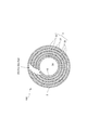
- the pole group is configured by, for example, alternately arranging a small number of 1-3 positive electrodes and a small number of 1-3 negative electrodes concentrically via a separator. It is a thing. Among them, the configuration in which the effect is most prominent is that the pole group is configured by concentrically arranging a single positive electrode and a single negative electrode wound once around a separator.
- the one-turn electrode has a hollow portion, and the loosening of the pole group accompanying charging / discharging is remarkable. In the case of one-turn winding, the thickness becomes relatively thick, and the force to press against the case surface increases.
- the strength of the pole group can be reduced, and the outer diameter of the pole group can be easily remarkably expanded or reduced.
- the present invention is particularly useful in batteries for devices (eg, remote controls) that operate on relatively low capacity batteries.
- a battery for this application usually has a structure that does not employ a technique for reducing internal resistance.
- An electrode having one turn means that the pole group is composed of one continuous negative electrode or one continuous positive electrode.
- a plurality of windings means that the electrode group includes two or more negative electrodes and two or more continuous positive electrodes.
- the concentration of KOH in the electrolytic solution can be increased from 7M to 8M.
- the concentration of KOH in the electrolytic solution can be increased from 7M to 8M.
- the concentration of the electrolytic solution it is possible to mitigate a decrease in the utilization rate of the active material.
- a holding member that is disposed between the hollow part of the pole group, the positive electrode and the separator, or between the negative electrode and the separator and presses and holds the pole group from the inside.
- the holding member presses the electrode group from the inside, it is possible to prevent a decrease in the current collection efficiency by preventing the active material from falling off due to the positive electrode or the negative electrode loosening to the inside.
- loosening of the positive electrode or the negative electrode is remarkable.
- the holding member holds the state in which the outer peripheral surface of the pole group and the inner peripheral surface of the battery case are pressed against each other, so that discharge efficiency (in the case of a primary battery) or charge / discharge efficiency (in the case of a secondary battery) Can be prevented. Further, by reducing the number of turns of the pole group wound in a cylindrical shape, the usage amount of the positive and negative electrode current collectors and separators can be greatly reduced, and the man-hours for manufacturing such as entrainment can be reduced.
- the holding member is disposed in the hollow portion of the pole group and presses the entire inner peripheral surface of the pole group. Is desirable.
- the holding member is made of an elastic plate, and is deformed into a cylindrical shape so that it is hollow, between the positive electrode and the separator, or between the negative electrode and the negative electrode.
- the outer peripheral surface of the pole group keeps pressing the inner peripheral surface of the battery case by pressing the pole group from the inside by its elastic restoring force.
- the plate is deformed into a cylindrical shape and placed in the pole group, but with its elastic return force, for example, the positive or negative electrode located on the innermost circumference is pressed toward the electrode case side. While preventing the active material from falling off, the outer peripheral surface of the pole group and the inner peripheral surface of the battery case can be reliably pressed. Moreover, it can respond to the hollow part of the pole group of various sizes only by deform
- the positive electrode and the negative electrode include a current collecting base material and an active material provided on the current collecting base material.
- the current collecting base material follows the volume change of the active material accompanying charge / discharge, and the electrical resistance can be kept low.
- the current collecting base material has elasticity and presses the electrode plate group. If this is the case, the electrode group can be pressed by the current collecting base material without using the holding member, and therefore, it is possible to prevent a decrease in current collecting efficiency by preventing the active material from falling off due to the loosening of the positive electrode or the negative electrode.
- an electrode having a current collection base material and an active material provided on one side and the other side of the current collection base material, It is desirable that the cover body is in contact with the active material and sandwiches the active material with the current collecting base material, the cover body has elasticity, and the cover body has electrical conductivity. .
- the cover body has electrical conductivity, the current collection path from the active material separated from the current collecting base material can be used as a path through the cover body, and the current collection efficiency can be improved.
- a nickel hydroxide active material is held on a foamed nickel porous body having a three-dimensional network structure with a porosity of 95% or more.
- a material using the foamed nickel porous body has excellent retention of the active material powder, and also has an excellent current collecting function.
- the current collecting base material made of a two-dimensional base material is different from the current collecting base material made of a foamed nickel porous body, and the active material is likely to fall off from the current collecting base material due to expansion and contraction of the active material accompanying charge / discharge.
- the distance between the substrate and the active material is long at a portion near the surface of the electrode plate, and the current collecting efficiency is low.
- a metal plate when used for the current collector substrate and the cover body, not only can it be thin, but it can be given strength, and its elasticity can be used to match the expansion and contraction of the active material. It can be set as the structure where a cover body always presses an active material with respect to a current collection base material.
- the cover body has strength so that the positive electrode active material can always be pressed using elasticity.
- the current collecting base material preferably has elasticity.
- the opening ratio of the cover body is preferably 5% or more and 60% or less. Similarly, if the current collecting base material has a large number of through holes penetrating in the thickness direction, movement of the electrolyte and ions is not hindered.
- the cover body is provided on one side of the current collecting base material. It is desirable to provide the 1st cover body which contacts the active material provided in this, and the 2nd cover body which contacts the active material provided in the other surface of the said current collection base material.
- the pole group is formed by alternately arranging, for example, a small number of one to three positive electrodes and a small number of one to three negative electrodes concentrically via a separator. What has been considered.
- the pole group has a plurality of positive electrodes or a plurality of negative electrodes, it is desirable to provide a cover for every positive electrode and negative electrode.
- the configuration in which the effect is most prominent is that the pole group is formed by concentrically arranging one positive electrode wound once and one negative electrode wound once through a separator. .
- the one-turn winding has a problem that the electrode is not particularly pressed and the friction between the electrodes is small and loosened. For this reason, the effect which prevents dropping of an active material by providing a cover body becomes especially remarkable.
- the pole group has a slit extending from one end in the axial direction to the other end in the axial direction, there is no step at the winding start portion, and the winding shape distortion caused by the winding start portion and the electrode overlapping the winding start portion The tearing of the electrode due to the deterioration of the part can be suppressed.
- transformation embodiment The cross-sectional view of the alkaline storage battery of deformation
- the cross-sectional view which shows the modification of a holding member.
- the cross-sectional view of the alkaline storage battery according to the second embodiment The cross-sectional view of the alkaline storage battery which concerns on deformation
- the secondary battery 100 is an alkaline storage battery such as a nickel / cadmium storage battery or a nickel / hydrogen storage battery.
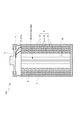
- a low capacity type cylindrical battery having an AA (AA) type capacity of 1800 mAh or less, or an AAA (AA) type capacity of 650 mAh or less, as shown in FIG. 1 and FIG.
- AA AA
- AAA AAA
- metal battery case 2 having a bottomed cylindrical shape and a cylindrical electrode plate group 3 arranged in the battery case 2 and made up of a positive electrode plate 31, a negative electrode plate 32 and a separator 33.
- the battery case 2 has a bottomed cylindrical shape with nickel plating, and the upper opening is sealed with a sealing body 5 via an insulator 4 as shown in FIG.
- a lead piece 311L provided to protrude from the upper end of the positive electrode plate 31 is connected to the back surface of the sealing body 5 directly or via a current collector (not shown), for example, by welding. It becomes the positive terminal.
- the outer peripheral surface 3n of the negative electrode plate 32 located on the outermost periphery of the electrode plate group 3 is in contact with the inner peripheral surface 2m of the battery case 2 (see the partially enlarged view of FIG. 2).
- the negative electrode plate 32 is connected to the battery case 2 via a current collector plate (not shown), and the battery case 2 itself becomes a negative electrode terminal.
- the electrode plate group 3 has a cylindrical shape in which the positive electrode plate 31 and the negative electrode plate 32 are alternately arranged concentrically with separators 33 made of, for example, a polyolefin nonwoven fabric.
- the separator is impregnated with an electrolytic solution such as potassium hydroxide.
- the positive electrode plate 31 is made of, for example, a positive electrode current collector made of a perforated steel sheet plated with nickel, and a positive electrode active material coated on the positive electrode current collector.
- the positive electrode current collecting base material may use nickel foam. Foamed nickel has excellent current collection efficiency.
- the positive electrode active material is, for example, nickel hydroxide in the case of a nickel / cadmium storage battery, and nickel hydroxide to which calcium hydroxide is added in the case of a nickel / hydrogen storage battery.
- the negative electrode plate 32 is made of a negative electrode current collector made of a perforated steel sheet plated with nickel in the same manner as the positive electrode plate 31, and a negative electrode active material coated on the negative electrode current collector.
- the negative electrode active material is, for example, a mixture of a cadmium oxide powder and a metal cadmium powder in the case of a nickel-cadmium storage battery.
- a nickel-hydrogen storage battery for example, mainly an AB 5 type (rare earth system) or is a powder of hydrogen absorbing alloy of AB 2 type (Laves phase).
- the positive electrode plate 31 and the negative electrode plate 32 are configured using a two-dimensional substrate such as a perforated steel plate, not a foamed substrate such as a nickel hole.
- the perforated steel sheet is more likely to fall off the active material than the foamed base material having a three-dimensional structure.
- the perforated steel sheet is more elastic than the foamed base material, so that the effect when the pole group is enlarged or reduced becomes remarkable. Further, when a plurality of perforated steel sheets are used, a more remarkable effect is observed.
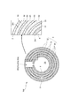
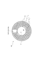
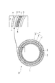
- the electrode plate group 3 has a linear slit 3S extending from one axial end to the other axial end along the axial direction.
- the positive electrode plate 31 the negative electrode plate 32, and the separator 33 are accommodated in the battery case 2, as shown in FIG. 2, from one axial end to the other axial end along the axial direction of the cylinder. It has linear slits 31a, 32a, 33a formed over it, and the cross section orthogonal to the axial direction forms a C-shape.
- the positive electrode plate 31 and the negative electrode plate 32 are alternately arranged concentrically through the separator 33 so that the slits 31a of the positive electrode plate 31 and the slits 32a of the negative electrode plate 32 face the same direction and communicate with each other. Yes.
- the electrode plate group 3 of the present embodiment two positively wound positive electrode plates 31 and two negatively wound negative electrode plates 32 are provided via a separator 33 so that the slits 31a and 32a are aligned in the radial direction. It is a double structure that is concentrically arranged so as to line up in the direction.
- the slit 3S of the electrode group 3 is formed when the slits 31a and 32a communicate with each other.
- AA AA size and positive electrode thickness is preferably 1.0-2.0 mm.
- the thickness of the negative electrode is preferably 0.3 to 0.8 mm.
- the positive electrode plate 31 and the negative electrode plate 32 expand and contract around a portion facing the portion where the slits 31a and 32a are formed.
- the relative movement between the negative electrode plates 32 is small, and the amount of slip can be reduced.
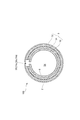
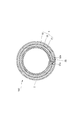
- FIG. 3 has a slit, the pole group can be expanded and contracted when the battery case is inserted, but the slit 31a of the positive electrode plate 31 and the slit 32a of the negative electrode plate 32 are arranged at different positions in the circumferential direction.
- the expansion / contraction center of the positive electrode plate 31 (part facing the slit 31a) and the expansion / contraction center of the negative electrode plate 32 (part opposing the slit 32a) are in different positions in the circumferential direction, and adjacent positive electrode plates 31 and the negative electrode plate 32 are less likely to move relative to each other, and it is difficult to expand and contract the outer diameter of the electrode plate group 3 as compared with the configuration of FIG.
- the alkaline storage battery 100 of this embodiment is arrange
- the holding member 6 is in contact with the inner peripheral surface 3 m of the electrode plate group 3, in this embodiment, the entire inner peripheral surface of the positive electrode plate 31 positioned at the innermost periphery.
- the holding member 6 made of a flat plate is curved and deformed into a cylindrical shape and is disposed in the hollow portion 3X of the electrode plate group 3, so that the outer peripheral surface 6n of the holding member 6 is made into an electrode plate by its elastic restoring force.
- the holding member 6 is preferably in contact with the entire inner peripheral surface 3m of the electrode plate group 3 so that its length dimension is not less than the inner peripheral length of the hollow portion 3X of the electrode plate group 3,
- the width dimension is desirably substantially equal to the axial length of the hollow portion 3X of the electrode plate group 3.
- the holding member 6 Since the holding member 6 is pressed against the inner peripheral surface 3m of the electrode plate group 3 by the holding member 6, not only does the positive electrode active material of the positive electrode plate 31 located at the innermost circumference fall off, but also the negative electrode The negative electrode active material on the plate 32 can be prevented from falling off. Thereby, the fall of current collection efficiency can be prevented. Moreover, since the holding member 6 holds the state where the outer peripheral surface 3n of the electrode plate group 3 and the inner peripheral surface 2m of the battery case 2 are in contact, the outer peripheral surface 3n of the electrode plate group 3 and the battery case 2 The contact with the inner peripheral surface 2m can be ensured to prevent the charge / discharge efficiency from being lowered. Further, since the holding member 6 is configured by deforming one plate into a cylindrical shape, the space in the battery 100 can be increased, the amount of the electrolyte can be increased, and the battery An increase in internal pressure can be prevented.
- the negative electrode plate 32 is welded and connected to the battery case 2 via a current collecting plate etc., for example. Thereafter, an electrolytic solution is injected into the battery case 2. Next, the holding member 6 deformed into a cylindrical shape smaller than the inner diameter of the hollow portion 3X is disposed in the hollow portion 3X of the electrode plate group 3. As a result, the electrode plate group 3 can be fixed to the battery case 2.
- the lead piece 311L of the positive electrode plate 31 is connected to the back surface of the sealing body 5 directly or via a current collector plate (not shown), and the sealing body 5 is connected to the upper opening of the battery case 2 via the insulator 4. Secure by caulking.
- each of the positive electrode plate 31, the negative electrode plate 32, and the separator 33 may be wound in a cylindrical shape and housed in the battery case 2 one by one, and the positions of the slits 31a and 32a of the positive electrode plate 31 and the negative electrode plate 32 are the same.
- a plurality of sets (for example, a set including one positive electrode plate 31, one separator 33, and one negative electrode plate 32) may be divided into a cylindrical shape and accommodated in the battery case 2. good.
- the slit 3S extending from one end in the axial direction to the other end in the axial direction is formed in the electrode plate group 3, the outer diameter of the electrode plate group 3 can be easily expanded or reduced by the slit 3S.
- the electrode plate group 3 is reduced in diameter so that the work of arranging the electrode plate group 3 in the battery case 2 is also performed without damaging the electrode plate group 3. Can do.
- the expansion / contraction centers are located at substantially the same position.
- the positive electrode plate 31 and the negative electrode plate 32 expand and contract around a portion facing the portion where the slits 31a and 32a are formed, the relative movement between the positive electrode plate 31 and the negative electrode plate 32 is small, and the amount of slip is made as small as possible. Because it can. Furthermore, the outer peripheral surface 3n of the electrode plate group 3 and the inner side of the battery case 2 are increased by expanding the outer diameter of the electrode plate group 3 by, for example, the holding member 6 in a state where the electrode plate group 3 is disposed in the battery case 2. Contact with the peripheral surface 2m can be ensured, and a decrease in charge / discharge efficiency can be prevented.
- the present invention is not limited to the first embodiment.
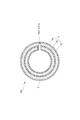
- the electrode plate group of the first embodiment has a double structure, but may have a single structure (see FIG. 4) or a triple structure or more. With a single structure, the strength of the electrode plate group 3 can be reduced, and the outer diameter of the electrode plate group 3 can be most easily expanded or reduced.
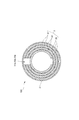
- the positive electrode plate 31 and the negative electrode plate 32 are provided so that the slits 31a and 32a are arranged along the radial direction. However, as shown in FIG. They may be arranged along the inclined direction and arranged alternately in concentric circles so that they communicate with each other.
- the slit 3S of the first embodiment has a linear shape along the axial direction.
- the slit 3S has a linear shape along the direction inclined with respect to the axial direction. It may be a shape that is curved or bent in a side view.
- the slit 31a of the positive electrode plate 31 and the slit 32a of the negative electrode plate 32 may have substantially the same width, or may have different slit widths.
- the holding member is disposed only in the hollow portion of the electrode plate group.
- the holding member may be provided between the positive electrode plate, the negative electrode plate, and the separator. good.
- a belt-shaped holding member is laminated between the positive electrode plate or the negative electrode plate and the separator, and the laminate is wound once to form a cylindrical electrode plate group.
- it may be provided between the negative electrode plate and the separator.
- the active material can be further prevented from falling off, and the outer peripheral surface of the electrode plate group can be reliably brought into contact with the inner peripheral surface of the battery case.
- the positive electrode and the negative electrode of the first embodiment were configured by applying an active material to a perforated steel sheet, but were also configured by filling an active material into a foamed substrate such as a nickel hole. It may be a thing.
- the current collecting base material constituting at least one of the positive electrode plate or the negative electrode plate has elasticity, and the electrode plate group may be pressed by the elasticity. If this is the case, the electrode plate group can be pressed by the current collecting base material without using a holding member, so that it is possible to prevent a decrease in current collecting efficiency by preventing the active material from falling off due to the loosening of the positive electrode plate or the negative electrode plate. it can.
- the negative electrode plate is located on the outermost periphery of the electrode plate group.
- the present invention is not limited to this, and the positive electrode plate may be located on the outermost periphery of the electrode plate group.
- the separator 33 has no slit.
- the separator 33 it is desirable to use a nonwoven fabric excellent in shrinkability.
- the separator 33 may be formed in a polyethylene bag shape, for example, and the positive electrode plate 31 may be accommodated in the bag-shaped separator.
- the present invention can be applied to secondary batteries such as lithium ion secondary batteries in addition to alkaline storage batteries, or may be applied to primary batteries.
- the secondary battery 100 according to the second embodiment is different from the first embodiment in the positive electrode plate 31, the negative electrode plate 32, and the separator 33 that constitute the electrode plate group 3.
- the positive electrode plate 31, the negative electrode plate 32, and the separator 33 are accommodated in the battery case 2 as shown in FIG. 10, extending from one axial end to the other axial end along the axial direction of the cylinder. It has the formed linear slits 31a, 32a, 33a, and the cross section orthogonal to the axial direction forms a C-shape.
- the positive electrode plate 31 and the negative electrode plate 32 are arranged so that the slits 31a of the positive electrode plate 31 and the slits 32a of the negative electrode plate 32 that are adjacent to each other through the separators 33 are different from each other in the circumferential direction.
- the different positions are positions where the slit 31a of the positive electrode plate 31 and the slit 32a of the negative electrode plate 32 do not overlap each other in the circumferential direction.
- the linear slits 31a, 32a, and 33a can be used to wrap the positive electrode plate 31, the negative electrode plate 32, and the separator 33 once around a member that has a rectangular shape in plan view, thereby simplifying the configuration. At the same time, manufacturing can be facilitated.
- the slits 31a of the plurality (two in FIG. 10) of the positive electrode plates 31 are arranged so as to face the same direction, and the slits 32a of the plurality (two in FIG. 10) of the negative electrode plates 32 face the same direction.
- the slit 31a of the positive electrode plate 31 and the slit 32a of the negative electrode plate 32 are arranged at positions opposite to each other in the circumferential direction, that is, at positions that differ by approximately 180 degrees in the circumferential direction.
- the slit 33a of the separator 33 is arranged so as to communicate in the same direction as one of the slit 31a of the positive electrode plate 31 or the slit 32a of the negative electrode plate 32 in order to ensure insulation of the positive electrode plate 31 and the negative electrode plate 32.
- two positively wound positive electrode plates 31 and two negatively wound negative electrode plates 32 are provided with a slit 33 a of the positive electrode plate 31 and the negative electrode plate 32 via a separator 33.
- the slits 31a of the positive electrode plate 31 and the slits 32a of the negative electrode plate 32 which are adjacent to each other through the separators 33 are arranged at different positions in the circumferential direction. Therefore, it is possible to make it difficult for the positive electrode plate 31 and the negative electrode plate 32 adjacent to each other to move relative to each other.
- the electrode plate group configured such that the slit 31a of the positive electrode plate 31, the slit 32a of the negative electrode plate 32, and the slit 33a of the separator 33 are in the same position in the circumferential direction.
- the positive electrode plate 31, the negative electrode plate 32, and the separator 33 expand and contract around a portion facing the portion where the slits 31 a, 32 a, 33 a are formed, so that the adjacent positive electrode plate 31 and negative electrode plate 32 move relative to each other.
- the positive electrode plate 31 and the negative electrode plate 32 are easily loosened.
- the alkaline storage battery 100 of this embodiment is arrange
- the configuration of the holding member 6 is the same as that in the first embodiment.
- a single negative electrode plate 32 having a rectangular shape is wound once and accommodated in the battery case 2 in a cylindrical shape.
- one rectangular separator 33 is wound once to be cylindrical and accommodated in the negative electrode plate 32 in the battery case 2.
- one positive electrode plate 31 having a rectangular shape is wound once so as to be cylindrical and accommodated in the separator 33 in the battery case 2.
- each negative electrode plate 32, each separator 33, and each positive electrode plate 31 is accommodated, the inner peripheral surface of the battery case 2 or the inner surfaces of the already accommodated electrode plates 31, 32 or the separator 33 so as to be expanded. So that it is in pressure contact. And after arrange
- the lead piece 311L of the positive electrode plate 31 is connected to the back surface of the sealing body 5 directly or via a current collector plate (not shown), and the sealing body 5 is connected to the upper opening of the battery case 2 via the insulator 4. Secure by caulking. It is conceivable that the connection between the negative electrode plate 32 and the current collector plate is made every time each negative electrode plate 32 is accommodated in the battery case 2. Alternatively, the electrolytic solution may be injected after the electrode plate group 3 is accommodated in the battery case 2 and the holding member 6 is disposed.
- the slit 31a of the positive electrode plate 31 and the slit 32a of the negative electrode plate 32 which are adjacent to each other via the separators 33 are arranged at different positions in the circumferential direction.
- the expansion / contraction center of the positive electrode plate 31 (the portion on the opposite side to the slit 31a in the positive electrode plate 31 (center portion in the circumferential direction)) and the expansion / contraction center of the negative electrode plate 32 (the portion on the opposite side of the slit 32a of the negative electrode plate 32) (Center portion in the circumferential direction)) become different positions in the circumferential direction, and the adjacent positive electrode plate 31 and negative electrode plate 32 can be made difficult to move relative to each other.
- the outer peripheral surface 3n of the electrode plate group 3 is pressed against the inner peripheral surface 2m of the battery case 2 or the positive electrode plate 31 and the negative electrode plate 32 constituting the electrode plate group 3 are pressed through the separator 33; After that, the positive electrode plate 31 and the negative electrode plate 32 can be made difficult to loosen. Accordingly, it is possible to prevent the charge / discharge efficiency of the secondary battery 100 from being lowered or the active material of the positive electrode plate 31 or the negative electrode plate 32 from dropping for a long period of time.
- the present invention is not limited to the second embodiment.
- all of the slits 31a of the positive electrode plate 31 and the slits 32a of the negative electrode plate 32 are configured to be opposite to each other in the circumferential direction, but are not limited to the opposite positions. As shown in FIG. 3 of the first embodiment, it may be an arbitrary position different in the circumferential direction. Thus, if the positions are different in the circumferential direction, it is not necessary to make the positions of the slits 31a of the positive electrode plate 31 and the slits 32a of the negative electrode plate 32 opposite to each other in the manufacturing stage of the battery 100, and the assembly work can be performed. The burden can be reduced.
- the said embodiment demonstrated the case where the slit 31a of the positive electrode plate 31 and the slit 32a of the negative electrode plate 32 which adjoin through all the separators 33 exist in a different position, as shown in FIG. Only the slit 31a of the positive electrode plate 31 and the slit 32a of the negative electrode plate 32 that are adjacent to each other may be located at different positions via the separator 33 (only the innermost periphery in FIG. 11) located on the innermost periphery side. .
- the other positive electrode plate 31 and negative electrode plate 32 are preferably arranged so that their slits 31a and 32a communicate in the same direction.
- the electrode plates 31 and 32 with the slits 31a and 32a facing in the same direction can be easily expanded and contracted, it can be easily brought into contact with the inner peripheral surface of the battery case 2, and the outer peripheral surface of the negative electrode plate 32 is the battery case 2
- the positive electrode plate 31 and the negative electrode plate 32 can be made difficult to loosen by arranging the innermost peripheral positive electrode plate 31 so that the slit 31a is on the opposite side while in contact with the inner peripheral surface.
- a third embodiment of the secondary battery according to the present invention will be described below with reference to the drawings.
- the same or corresponding members as those in the first and second embodiments are denoted by the same reference numerals.
- the configuration of the present embodiment can be used in combination with the first and second embodiments, or can be configured not to be combined with the first and second embodiments.
- the secondary battery 100 is, for example, a low capacity type having an AA (AA) type capacity of 1800 mAh or less, or an AAA (AA) type capacity of 650 mAh or less.
- AA AA
- AAA AAA
- 12 and 13 a metal battery case 2 having a bottomed cylindrical shape, and a positive electrode plate 31, a negative electrode plate 32, and a separator 33 disposed in the battery case 2.
- a cylindrical electrode plate group 3 made of
- the battery case 2 has a bottomed cylindrical shape with nickel plating, and the upper opening is sealed with a sealing body 5 via an insulator 4 as shown in FIG.
- a lead piece 311L provided to protrude from the upper end of the positive electrode plate 31 is connected to the back surface of the sealing body 5 directly or via a current collector (not shown), for example, by welding. It becomes the positive terminal.
- the outer peripheral surface 3n of the negative electrode plate 32 located on the outermost periphery of the electrode plate group 3 is in contact with the inner peripheral surface 2m of the battery case 2 (see a partially enlarged view of FIG. 13). .
- the electrode plate group 3 has a cylindrical shape in which the positive electrode plate 31 and the negative electrode plate 32 are alternately arranged concentrically with separators 33 made of, for example, a polyolefin nonwoven fabric.
- the separator is impregnated with an electrolytic solution such as potassium hydroxide.
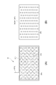
- the positive electrode plate 31 includes a positive electrode current collector base material 311 made of a metal plate in which a large number of through holes 31 h penetrating in the thickness direction are formed, and a through hole 31 h in the positive electrode current collector base material 311. And a positive electrode active material 312 provided on one surface 311a and the other surface 311b (hereinafter also referred to as both surfaces) of the positive electrode current collector base material 311.
- the positive electrode current collector base material 311 has a substantially rectangular shape in a plan view in a developed state, and a lead piece 311L is provided at the upper end thereof.
- the positive electrode current collector base material 311 is a perforated steel plate in which a through hole 31h is formed by punching a flat metal plate (for example, a rolled sheet), for example, plated with nickel. Steel is preferable because it can be compressed sufficiently as a material.
- the thickness is preferably 10 ⁇ m or more, more preferably 20 ⁇ m or more.
- the opening ratio of the through holes 31h of the positive electrode current collector base material 311 is, for example, 5% or more and 60% or less.
- the opening ratio is less than 5%, the active material holding function is lowered, and when the aperture ratio exceeds 60%, the current collecting function may be lowered.
- the opening shape of the through-hole 31h is circular,
- the opening diameter is 0.5 mm or more and 2.0 mm or less.
- those having an opening diameter of less than 0.5 mm are difficult to manufacture, and if the opening diameter exceeds 2.0 mm, the current collecting function may be deteriorated.
- the opening shape of the through hole 31h various shapes such as an ellipse, an oval, a triangle, a rectangle, a rhombus, and other polygons can be used.
- the opening diameter here is the diameter in the case of a circle, the short diameter in the case of an ellipse, the length of the shortest side in the case of a triangle, and a polygon such as a rectangle or rhombus. In this case, it refers to the minimum diagonal length.
- the positive electrode active material 312 is provided almost evenly on both surfaces of the positive electrode current collector 311.
- it is nickel hydroxide
- nickel hydroxide to which calcium hydroxide is added for example, Nickel hydroxide to which calcium hydroxide is added.
- the positive electrode active material 312 may be provided by being applied to the positive electrode current collector 311 or may be provided by compression molding.
- the negative electrode plate 32 is made of a negative electrode current collecting substrate made of a perforated steel plate plated with nickel similarly to the positive electrode plate 31, and a negative electrode active material coated on the negative electrode current collecting substrate.
- the negative electrode active material is, for example, a mixture of a cadmium oxide powder and a metal cadmium powder in the case of a nickel-cadmium storage battery.
- a nickel-hydrogen storage battery for example, mainly an AB 5 type (rare earth system) or is a powder of hydrogen absorbing alloy of AB 2 type (Laves phase).
- the positive electrode plate 31 and the negative electrode plate 32 are configured using a two-dimensional base material such as a perforated steel plate instead of a foam base material such as a nickel hole.
- the perforated steel sheet is more likely to fall off the active material than the foamed base material having a three-dimensional structure.
- the perforated steel sheet is more elastic than the foamed base material, so that the effect when the electrode plate group is enlarged or reduced becomes remarkable. Further, when a plurality of perforated steel sheets are used, a more remarkable effect is observed.
- a cover body 34 that covers the entire both surfaces of the positive electrode plate 31 is disposed.
- the cover body 34 is made of a metal plate in which a large number of through holes 34 h penetrating in the thickness direction are formed.
- the cover body 34 is in contact with the positive electrode active material 312 and sandwiches the positive electrode active material 312 between the positive electrode current collector base material 311. It is a waste.
- the cover body 34 includes a first cover body 341 that is in contact with the positive electrode active material 312 provided on one surface 311 a of the positive electrode current collector base material 311, and a positive electrode current collector base material.
- a second cover body 342 that contacts the positive electrode active material 312 provided on the other surface 311b of 311.
- the positive electrode plate 31 is sandwiched between the first cover body 341 and the second cover body 342.
- the first cover body 341 and the second cover body 342 have substantially the same shape as each other, and have a substantially rectangular shape in a plan view in a developed state as shown in FIG. It has substantially the same shape as the portion excluding the lead piece portion 311L of the positive electrode current collector base material 311. Further, the first cover body 341 and the second cover body 342 are perforated steel plates plated with nickel, for example, similarly to the positive electrode current collector base material 311, and the through holes 34 h have the positive electrode current collector base material 311. The through hole 31h has the same shape and the same opening ratio. That is, the first cover body 341 and the second cover body 342 have the same configuration as that of the positive electrode current collector base material 311, thereby reducing the manufacturing cost.
- the cover body 34 that sandwiches the positive electrode plate 31 may be plated with a metal other than nickel, and is stable at the potential of the positive electrode plate 31, specifically, made of nickel, or other than nickel. It may be a cover body in which a metal or resin is plated with nickel.
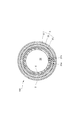
- the electrode plate group 3 of the present embodiment is configured so that the positive electrode plate 31 and the negative electrode plate 32 are axially extended from one end in the axial direction along the axial direction of the cylinder. It has linear slits 31a and 32a formed over the other end in the direction, and the cross section orthogonal to the axial direction forms a C-shape.
- the positive electrode plate 31 and the negative electrode plate 32 are alternately arranged concentrically through the separator 33 so that the slits 31a of the positive electrode plate 31 and the slits 32a of the negative electrode plate 32 face the same direction and communicate with each other. Yes.
- the positive electrode plate 31 and the negative electrode plate 32 are formed with slits 31a and 32a. Therefore, when the electrode plate group 3 is inserted into the battery case 2, the diameter can be easily reduced, and it is easy to press the electrode plate group 3 against the battery case 2 after the insertion. Can be.
- the slits 31a and 32a of the positive electrode plate 31 and the negative electrode plate 32 may be arranged at different positions in the circumferential direction.
- the electrode plate group 3 can be expanded and contracted when the battery case is inserted, but the electrode plate group 3 is configured such that the slit 31a of the positive electrode plate 31 and the slit 32a of the negative electrode plate 32 are arranged at different positions in the circumferential direction. Then, the expansion / contraction center of the positive electrode plate 31 (part facing the slit 31a) and the expansion / contraction center of the negative electrode plate 32 (part opposing the slit 32a) are in different positions in the circumferential direction, and the adjacent positive electrode plate 31 and negative electrode plate 32 are adjacent to each other. It becomes difficult to move relatively, and the positive electrode plate 31 and the negative electrode plate 32 can be made difficult to loosen after being inserted into the battery case 2.
- the first cover body 341 and the second cover body 342 are arranged on both surfaces of one positive electrode plate 31 so that the single positive electrode plate 31 is sandwiched between the first and second cover bodies 341 and 342.
- the structure configured as described above and one negative electrode plate 32 are stacked with a separator 33 interposed therebetween. And the laminated body comprised in this way is wound 1 round, the cylindrical electrode group 3 is formed, and it arrange
- the electrode plate group 3 is disposed in the battery case 2, the outer diameter of the electrode plate group 3 is reduced due to the slit 31 a of the positive electrode plate 31 and the slit 32 a of the negative electrode plate 32. It is possible to prevent a problem that the negative electrode active material on the outer peripheral surface 3n of the group 3 is scraped in contact with the battery case 2.
- the electrode plate group 3 is arranged in the battery case 2 and then the negative electrode plate 32 is connected to the battery case 2 by welding, for example, via the current collector plate. Thereafter, an electrolytic solution is injected into the battery case 2.
- the lead piece 311L of the positive electrode plate 31 is connected to the back surface of the sealing body 5 directly or via a current collector plate (not shown), and the sealing body 5 is connected to the upper opening of the battery case 2 via the insulator 4. Secure by caulking.
- each of the positive electrode plate 31, the negative electrode plate 32, and the separator 33 may be wound in a cylindrical shape and housed in the battery case 2 one by one.
- a sealed nickel-metal hydride battery that is an alkaline storage battery of the present invention, that is, a perforated steel sheet applied to a positive electrode current collector base material, a positive electrode active material applied, and a cover body provided (positive current collector base material: perforated steel sheet, Cover body: Yes, and a conventional sealed nickel-metal hydride battery, that is, a foamed nickel porous body used as a positive electrode current collector base material to hold the positive electrode active material and not provided with a cover body (positive electrode current collector base material: foamed) Nickel porous body, cover body: none) and a nickel foam porous body used as a positive electrode current collector base material to hold a positive electrode active material and provided with a cover body (positive electrode current collector base material: foam nickel porous body, cover Body: Yes) and 0.2 ItA of a positive electrode active material applied using a perforated steel plate as a positive electrode current collecting base material and a cover body not provided (positive current collecting base material: perforated steel plate, cover
- the positive electrode active material is 3% by mass of zinc and 0.6% by mass of cobalt.
- a nickel hydroxide surface containing 6% by weight in a solid solution state and coated with 6% by mass cobalt hydroxide was subjected to air oxidation treatment at 110 ° C. for 1 hour using an 18M sodium hydroxide solution.
- aqueous solution in which a thickener (carboxymethylcellulose) is dissolved, and an active material and further a PTFE (polytetrafluoroethylene) aqueous solution are mixed in an amount of 0.3% by mass to produce a paste, which is then filled into a nickel foam substrate. After drying, the positive electrode plate was obtained by pressing to a predetermined thickness (0.97 mm).
- a thickener carboxymethylcellulose
- PTFE polytetrafluoroethylene
- the positive electrode current collecting base material is a foamed nickel porous body and has a cover body
- a positive electrode plate was produced in the same manner as in the above (2-1), and a 35 ⁇ m thick perforated steel plate (opening) The both sides of the positive electrode plate were sandwiched at a rate of 50% and a hole diameter of 1 mm.
- the positive electrode active material has a surface of nickel hydroxide containing 3% by weight of zinc and 0.6% by weight of cobalt in a solid solution state. What coated 6 mass% cobalt hydroxide was used what was air-oxidized for 1 hour at 110 degreeC using 18M sodium hydroxide solution.
- a paste is prepared by mixing an aqueous solution in which a thickener (carboxymethylcellulose) is dissolved, an active material and an SBR aqueous solution at a solid content of 1% by mass, and a PTFE aqueous solution at a solid content of 0.5% by mass. The thickness is 35 ⁇ m. After being coated on both sides of a perforated steel sheet (opening ratio 50%, hole diameter 1 mm) and dried, it was pressed to a thickness of 0.96 mm to obtain a positive electrode plate.
- the positive electrode current collecting base material is a perforated steel plate and has a cover body
- a positive electrode plate is prepared in the same manner as in (2-3) above, and a perforated steel sheet having a thickness of 35 ⁇ m (opening ratio 50) %, The diameter of the hole is 1 mm).
- the discharge efficiency is lower than that using the porous nickel foam.
- the presence or absence of the cover body does not significantly affect the punched steel plate.
- the discharge efficiency is remarkably improved by providing a cover body.
- the discharge efficiency at a high rate is improved by providing the cover body.
- a material using a perforated steel plate as a positive electrode current collector has a higher discharge efficiency when discharged at a low rate of 0.2 ItA than when discharged at a high rate of 1 ItA.
- the positive electrode plate 31 configured by holding the positive electrode active material 312 on the positive electrode current collecting base material 311 made of a perforated steel plate having a large number of through holes 31h. Is sandwiched between the first cover body 341 and the second cover body 342, the positive electrode active material 312 can be prevented from falling off from the positive electrode current collector base material 311, and the current collection efficiency can be improved. it can. Further, since the cover bodies 341 and 342 are made of perforated steel plates, the current collection path from the positive electrode active material 312 away from the positive electrode current collector base material 311 can be a path via the cover bodies 341 and 342.
- both the positive electrode current collector base material 311 and the cover bodies 341 and 342 are made of a perforated steel plate having a large number of through holes 31h, movement of the electrolyte and ions is not hindered.
- the perforated steel plates are used for the positive electrode current collector base material 311 and the cover bodies 341 and 342, not only can a thin material be provided with strength, but also the positive electrode active material 312 can be obtained using its elasticity.
- the cover bodies 341 and 342 can always be configured to press the positive electrode active material 312 against the positive electrode current collector 311 in accordance with the expansion and contraction of the positive electrode current collector 311.
- the electrode plate group of the third embodiment is configured by concentrically arranging a positive electrode plate wound once and a negative electrode plate wound once around via a separator.
- the plurality of positive electrodes and the plurality of negative electrodes may be alternately arranged concentrically with a separator interposed therebetween.
- the cover body is disposed on both surfaces of the positive electrode plate.
- the cover body may be disposed on any one surface.
- it is easy to loosen without applying a compression force to the innermost electrode plate group, so both surfaces of the innermost positive electrode plate or negative electrode plate or It is desirable to arrange the cover body on one side.
- the cover body that sandwiches the negative electrode plate is preferably one that is stable at the potential of the negative electrode plate, specifically, one obtained by subjecting copper, nickel, or iron to nickel plating.
- one cover body is disposed on one surface and the other surface of the positive electrode plate, respectively, but other cover bodies are disposed on the one surface and the other surface of the positive electrode plate, respectively.
- the cover piece may be divided into a plurality of pieces in the circumferential direction or the axial direction.
- a perforated steel plate is used for the positive electrode current collector, but an expanded metal may be used.
- the opening ratio of the expanded metal is preferably 5% or more and 60% or less. When the opening ratio is less than 5%, the active material holding function is lowered, and when the opening ratio is more than 60%, the current collecting function may be lowered.
- the alkaline storage battery 100 of the third embodiment is disposed in the hollow portion 3X of the electrode plate group 3 and contacts the inner peripheral surface of the electrode plate group 3.
- 3 is preferably provided with a holding member 6 that holds the outer peripheral surface 3n in contact with the inner peripheral surface 2m of the battery case 2.
- the configuration of the holding member 6 is the same as that of the first embodiment.
- the negative electrode plate is positioned on the outermost periphery of the electrode plate group.
- the present invention is not limited to this, and the positive electrode plate may be positioned on the outermost periphery of the electrode plate group.
- the separator for example, a polyethylene bag-like shape may be used, and the positive electrode plate 31 may be accommodated in the bag-like separator.
- the cylindrical battery has been described in the third embodiment, a rectangular battery may be used.
- the present invention can be applied to a secondary battery such as a lithium ion secondary battery, or may be applied to a primary battery.
Landscapes
- Chemical & Material Sciences (AREA)
- Chemical Kinetics & Catalysis (AREA)
- Electrochemistry (AREA)
- General Chemical & Material Sciences (AREA)
- Engineering & Computer Science (AREA)
- Materials Engineering (AREA)
- Manufacturing & Machinery (AREA)
- Secondary Cells (AREA)
- Cell Electrode Carriers And Collectors (AREA)
- Cell Separators (AREA)
Abstract
本発明は、円筒形電池において、ケース挿入時の電極の外径を拡縮容易に構成するものであり、円筒状の電池ケース2と、当該電池ケース2内に配置され、正極31、負極32及びセパレータ33を含む円筒状の極群3とを有し、前記極群3が、軸方向一端から軸方向他端に亘って延びるスリット3Sを有することを特徴とする。
Description
本発明は、例えばアルカリ蓄電池やリチウムイオン二次電池等の円筒形電池及び例えばアルカリ蓄電池やリチウムイオン二次電池等の電池に用いられる電池用電極構造に関するものである。
ニッケル・カドミウム蓄電池、ニッケル・水素蓄電池等のアルカリ蓄電池における円筒形電池としては、例えば特許文献1に示すように、帯状の正極板と負極板とをセパレータを介して渦巻き状に巻いて構成した極板群を円筒形の電池ケース(電池外装缶、電槽缶等という。)に収納して密封した電池がある。この円筒形電池では、高容量化を図るために、帯状の正極板と負極板とをセパレータを介して、電池ケース内がほぼ中実となるように渦巻き状に巻いて円柱状とした極板群を電池ケース内に収納して構成されている。
一方、本出願人は、近年の高容量化が進んでいる円筒形電池において、用途に応じた低容量の円筒形電池の開発を進めている。具体的には、例えば帯状の正極板と負極板を渦巻き状に巻く回数を減らして円筒状の電極群を電池ケース内に収容すること等を考えている。
しかしながら、上記のように渦巻き状に巻いて構成した極群においては、電極の巻き始め部分による段差が巻回形状に歪みを起こし、当該巻き始め部分と重なり合う電極部分の劣化により当該電極部分の電極が断裂してしまうという問題がある。
そこで本発明は、上記問題点を一挙に解決すべくなされたものであり、円筒状の極群において、巻き始め部分の段差による巻回形状の歪み及び巻き始め部分の段差による電極の断裂を防止することをその主たる所期課題とするものである。
すなわち本発明に係る円筒形電池は、円筒状の電池ケースと、当該電池ケース内に配置され、正極、負極及びセパレータを含む円筒状の極群とを有し、前記極群が、軸方向一端から軸方向他端に亘って延びるスリットを有することを特徴とする。
このようなものであれば、極群に軸方向一端から軸方向他端に亘って延びるスリットを形成しているので、巻き始め部分の段差を無くして当該巻き始め部分に起因する巻回形状の歪み及び巻き始め部分と重なり合う電極部分の劣化による電極の断裂を抑制することができる。
ここで、スリットを有するとは、1枚の連なった電極において、電極の巻き始めの一端から巻き終わりの他端が、周方向において角度が360度未満であることをいう。つまり、1枚の連なった電極が重なり部分を有さず、電極の巻き始めの一端と巻き終わりの他端との間に、隙間を有することである。
また、従来の渦巻き状に巻いた極群の外径は、ほぼ巻く段階で決まってしまう。極板間の摩擦により、外径の拡縮が容易にできないからである。そうすると、極群の外径が電池ケースの内径よりも小さい場合には、極群の最外周と電池ケースの内側周面との接触が不十分となり、充放電効率が低下するという問題がある。一方、極群の外径が電池ケースの内径よりも大きい場合には、極群を電池ケース内に収容することが難しく、極群の最外周に位置する極板に保持された活物質が電池ケースに削られてしまう等の恐れがある。
極群に軸方向一端から軸方向他端に亘って延びるスリットを形成していることで、当該スリットによって極群の外径を拡縮させ易くすることができる。これにより、電池ケース内に極群を配置した状態で極群の外径を拡径することで、電池ケースの内側周面に極群を押圧させる構成を容易にすることができ、充放電効率の低下を防止することができる。また、電池ケース内に極群を配置する段階で、極群を縮径することで、極群を電池ケース内に配置する作業も極群を傷つけることなく行うことができる。
極群の構成を簡単にするとともにその製造を容易にするためには、前記極群が、軸方向に沿って軸方向一端から軸方向他端に亘って延びる直線状のスリットを有することが望ましい。
極群の具体的な実施の態様としては、前記正極及び前記負極が、軸方向に沿って軸方向一端から軸方向他端に亘って延びるスリットを有する断面C字形状をなすものであり、前記極群が、前記正極及び前記負極を前記セパレータを介して、それらのスリットが互いに連通するように配置して構成されていることが考えられる。これならば、正極及び負極がスリットが形成された部分と対向する部分を中心として拡縮するため、それらの拡縮中心がほぼ同一位置となるため、正極及び負極間の相対移動が小さく滑り量を小さくすることができる。このため極群のスリットが顕著に拡縮しやすくすることができる。スリットが互いに連通するように配置する態様としては、正極のスリット及び負極のスリットが同一方向を向くように配置すること等が考えられる。
前記極群が、前記正極及び前記負極を前記セパレータを介して配置して構成されるものであり、前記極群において少なくとも一組のセパレータを介して隣り合う正極のスリット及び負極のスリットが、周方向において互いに異なる位置に配置されていることが望ましい。これならば、軸方向一端から軸方向他端に亘って延びるスリットを有しているので、極群を拡縮しやすく、容易に電池ケースへ極群を挿入し、電池ケースへ挿入した後は電池ケースに極群を押圧した状態にすることができる。さらに、セパレータを介して隣り合う正極のスリット及び負極のスリットが周方向において互いに異なる位置に配置されているので、それら正極の拡縮中心(正極におけるスリットとは反対側の部分)及び負極の拡縮中心(負極におけるスリットとは反対側の部分)が周方向において異なる位置となり、隣り合う正極及び負極同士を相対移動しにくくすることができる。これにより、極群の外側周面を電池ケースの内側周面に押圧接触又は極群を構成する正極及び負極をセパレータを介して押圧させた状態とした後に正極及び負極を緩みにくくすることができる。したがって、電池の充放電効率の低下又は正極又は負極の活物質の脱落を長期間にわたって防止することができる。
特に極群の最内周側において極板が緩みやすいと考えられることから、前記極群の少なくとも最内周側にあるセパレータを介して隣り合う正極のスリット及び負極のスリットが、周方向において互いに異なる位置に配置されていることが望ましい。
前記極群の各セパレータを介して隣り合う正極のスリット及び負極のスリットが、それぞれ周方向において互いに異なる位置に配置されていることが望ましい。これならば、極群を構成する正極及び負極の全てにおいて、隣り合う正極及び負極が相対移動をしにくくすることができ、電極の緩み抑制の効果を一層顕著にすることができる。
隣り合う正極及び負極同士を最も移動しにくくする効果を一層顕著にするためには、前記異なる位置が、周方向において反対側の位置であることが望ましい。
本発明の効果を一層顕著にする構成として、極群が例えば1~3枚の少数の正極及び1~3枚の少数の負極のそれぞれをセパレータを介して同心状に交互に配置して構成されたものである。その中でも効果が最も顕著に現れる構成は、前記極群が、一周巻きした1枚の正極及び一周巻きした1枚の負極をセパレータを介して同心状に配置して構成されたものである。一周巻きの電極は、中空部が形成され、充放電に伴う極群の緩みが顕著である。一周巻きの場合は、厚みが比較的厚くなり、ケース面へ押圧する力が大きくなる。ケース面への圧力が大きくなると、巻き始めの段差による電極の断裂が顕著になるので、スリットを有して巻き始めの段差を無くす効果は大きい。極群の強度を小さくすることができ、極群の外径をさらに顕著に拡縮させ易くできる。本発明は、比較的低容量電池で作動するデバイス(例えば、リモコン)用の電池において特に有用である。当該用途の電池は、通常、内部抵抗を低減するための技術を採用しない構造を有する。例えば、最外周の極板の端部に集電体を溶接する技術、ケース挿入後の極群の拡径を避けるために電極の端部にテープを貼付する技術を採用せずに、電極ケースと最外周の電極が接触することが部品点数の点で好ましい。
電極が一周巻きであるとは、極群が1枚の連なった負極又は1枚の連なった正極から構成されていることである。電極が複数巻きであるとは、極群が2枚以上の負極及び2枚以上の連なった正極を含むことである。
また、電解液の濃度が高い方が活物質の利用率の点で好ましい。例えば、電解液中のKOHの濃度を7Mから8Mにすることを挙げることができる。一周巻きの場合には、正極に対する負極の面積が従来に比べて小さいので、内部抵抗が大きくなり、活物質の利用率が低下する虞がある。電解液の濃度を高くすることで、活物質の利用率低下を緩和することができる。
前記極群の中空部、前記正極及び前記セパレータの間、又は前記負極及び前記セパレータの間に配置され、前記極群を内側から押圧し保持する保持部材とを有することが望ましい。これならば、保持部材が極群を内側から押圧していることから、正極又は負極が内側に緩むことによる活物質脱落の防止により集電効率の低下を防ぐことができる。特に中空部を有する場合には、正極又は負極の緩みが顕著である。また、保持部材が、極群の外側周面と電池ケースの内側周面とが互いに押圧した状態を保持することによって、放電効率(一次電池の場合)又は充放電効率(二次電池の場合)の低下を防止することができる。さらに円筒状に巻く極群の巻数を減らすことによって、正極及び負極の集電体及びセパレータの使用量を大幅に削減することができ、それらの巻き込み等の製造の工数を削減することもできる。
ここで、極群全体の活物質の脱落を最大限に防止するためには、前記保持部材が、極群の中空部に配置されて前記極群の内側周面全体を押圧するものであることが望ましい。
前記保持部材の具体的な実施の態様としては、前記保持部材が弾性を有する板からなり、筒状に変形されて前記極群の中空部、前記正極及び前記セパレータの間、又は前記負極及び前記セパレータの間に配置されることにより、その弾性復帰力によって、前記極群を内側から押圧することで、前記極群の外側周面が前記電池ケースの内側周面を押圧した状態を保持するものを挙げることができる。これならば、板を筒状に変形させて極群内に配置するという簡単な構成でありながら、その弾性復帰力により、例えば最内周に位置する正極又は負極を電極ケース側に押圧して活物質の脱落を防止するとともに、確実に極群の外側周面と電池ケースの内側周面とを押圧させることができる。また、板を種々のサイズの筒状に変形させるだけで、種々のサイズの極群の中空部に対応できる。
正極及び負極の具体的な実施の態様としては、前記正極及び前記負極が、集電基材と当該集電基材に設けられた活物質とを備えるものであることが考えられる。集電基材を有することで、充放電に伴う活物質の体積変化に集電基材が追従して、電気抵抗を低く保つことができる。また、前記集電基材が弾性を有し、前記極板群を押圧することが望ましい。これならば、保持部材を用いることなく集電基材により極群を押圧することができるので、正極又は負極が緩むことによる活物質脱落の防止により集電効率の低下を防ぐことができる。
活物質の脱落を防止するとともに集電効率を改善するための電池用電極構造としては、集電基材及び当該集電基材の一方面及び他方面に設けられた活物質を有する電極と、前記活物質に接触して前記集電基材との間で前記活物質を挟むカバー体とを備え、前記カバー体が弾性を有し、且つ、前記カバー体が電気伝導性を有することが望ましい。
このようなものであれば、集電基材に活物質を保持させて構成される電極にカバー体を配置することによって、集電基材から活物質が脱落することを防止することができ、集電効率を改善することができる。また、カバー体が電気伝導性を有することから、集電基材から離れた活物質からの集電経路をカバー体を介した経路とすることもでき集電効率を改善することができる。
アルカリ蓄電池の正極板としては、多孔度が95%以上の三次元の網目構造を有する発泡ニッケル多孔体に水酸化ニッケル活物質を保持させたものがある。この発泡ニッケル多孔体を用いたものは、活物質粉末の保持性に優れており、また集電機能も優れている。
発泡ニッケル多孔体の替わりに、パンチングメタルやエキスパンドメタル等の金属板に加工を施してなる二次元基材を用いたものが考えられている。
二次元基材からなる集電基材は発泡ニッケル多孔体からなる集電基材とは異なり、充放電に伴う活物質の膨張収縮等により、活物質が集電基材から脱落し易い。また、二次元基材からなる集電基材に活物質を保持させたものでは、極板の表面に近い部分では基板と活物質との距離が遠く、集電効率が低い。カバー体を備えることで、活物質の脱落を抑制し、集電効率を高めることができる。
また、集電基材及びカバー体に金属板を用いた場合には、薄いものであっても強度を持たせることができるだけでなく、その弾性を利用して、活物質の膨張収縮に合わせてカバー体が集電基材に対して活物質を常に圧迫する構造とすることができる。
ここで、カバー体は弾性を利用して正極活物質を常に圧迫できるよう、強度をもっていることが好ましい。集電基材は弾性を有することが好ましい。
前記カバー体が、厚さ方向に貫通する多数の貫通孔を有するものであれば、電解液やイオンの移動を妨げることもない。カバー体の開口率は5%以上60%以下であることが好ましい。同様に、前記集電基材が、厚さ方向に貫通する多数の貫通孔を有するものであれば、電解液やイオンの移動を妨げることもない。
集電基材の一方面及び他方面に設けられた活物質の両方の脱落を防止することによって集電効率をより一層改善するためには、前記カバー体が、前記集電基材の一方面に設けられた活物質に接触する第1のカバー体と、前記集電基材の他方面に設けられた活物質に接触する第2のカバー体とを備えることが望ましい。
前記カバー体の効果を一層顕著にする構成として、極群が例えば1~3枚の少数の正極及び1~3枚の少数の負極のそれぞれをセパレータを介して同心状に交互に配置して構成されたものが考えられる。極群が複数の正極又は複数の負極を有するものである場合には、全ての正極及び負極毎にカバー体を設けることが望ましい。その中でも効果が最も顕著に現れる構成は、前記極群が、1周巻きした1枚の正極及び1周巻きした1枚の負極をセパレータを介して同心状に配置して構成されたものである。このように1周巻きのものは、特に電極に圧迫力がかからず、電極間の摩擦が小さく緩んでしまうという問題がある。このため、カバー体を設けることによって活物質の脱落を防止する効果が特に顕著となる。
極群が軸方向一端から軸方向他端に亘って延びるスリットを有する構成によれば、巻き始め部分の段差を無くして当該巻き始め部分に起因する巻回形状の歪み及び巻き始め部分と重なり合う電極部分の劣化による電極の断裂を抑制することができる。
以下に本発明に係る二次電池の第1実施形態について図面を参照して説明する。
第1実施形態に係る二次電池100は、ニッケル・カドミウム蓄電池やニッケル・水素蓄電池等のアルカリ蓄電池である。具体的には、例えばAA(単3)形の容量が1800mAh以下、又はAAA(単4)形の容量が650mAh以下である低容量タイプの円筒形電池であり、図1及び図2に示すように、有底円筒状をなす金属製の電池ケース2と、この電池ケース2内に配置され、正極板31、負極板32及びセパレータ33からなる円筒状の極板群3とを有するものである。
電池ケース2は、ニッケルめっきを施した有底円筒状をなすものであり、図1に示すように、上部開口は絶縁体4を介して封口体5により封止されている。また、封口体5の裏面には、正極板31の上端部に突出して設けられたリード片部311Lが例えば溶接により直接又は集電板(不図示)を介して接続されて、封口体5が正極端子となる。なお、後述するように、電池ケース2の内側周面2mに極板群3の最外周に位置する負極板32の外側周面3nが接触するとともに(図2の部分拡大図参照)、その他の負極板32は集電板(不図示)を介して電池ケース2に接続されて、電池ケース2自体が負極端子となる。
極板群3は、正極板31及び負極板32を例えばポリオレフィン製の不織布からなるセパレータ33を介して同心円状に交互に配置して構成される円筒形状をなすものである。なおセパレータには例えば水酸化カリウム等の電解液が含侵される。
正極板31は、例えばニッケルめっきを施した穿孔鋼板からなる正極集電体と、この正極集電体上に塗布された正極活物質とからなる。正極集電基材は発泡ニッケルを用いてもよい。発泡ニッケルは集電効率が優れる。なお正極活物質としては、ニッケル・カドミウム蓄電池の場合には、例えば水酸化ニッケルであり、ニッケル・水素蓄電池の場合には、例えば水酸化カルシウムを添加した水酸化ニッケルである。
負極板32は、前記正極板31と同様にニッケルめっきを施した穿孔鋼板からなる負極集電体と、この負極集電体上に塗布された負極活物質からなる。なお負極活物質としては、ニッケル・カドミウム蓄電池の場合には、例えば酸化カドミウム粉末と金属カドミウム粉末との混合物であり、ニッケル・水素蓄電池の場合には、例えば主にAB5型(希土類系)又はAB2型(Laves相)の水素吸蔵合金の粉末である。なお、正極板31及び負極板32をニッケル孔体等の発泡状基材ではなく、穿孔鋼板といった二次元基材を用いて構成している。穿孔鋼板は三次元の構造を有している発泡状基材に比べ、活物質の脱落は起こりやすい。一方、穿孔鋼板は発泡状基材より弾性を有しているので、極群を拡縮させたときの効果は顕著になる。さらに複数枚の穿孔鋼板を用いたときは、いっそう顕著な効果がみられる。
そして、極板群3は、図1及び図2に示すように、軸方向に沿って軸方向一端から軸方向他端に亘って延びる直線状のスリット3Sを有する。
具体的には、正極板31、負極板32及びセパレータ33が、電池ケース2に収容された状態において、図2に示すように、円筒の軸方向に沿って軸方向一端から軸方向他端に亘って形成された直線状のスリット31a、32a、33aを有し、軸方向に直交する断面がC字形状をなすものである。これら正極板31及び負極板32は、セパレータ33を介して、正極板31のスリット31a及び負極板32のスリット32aが同一方向を向き、それらが互いに連通するように同心円状に交互に配置されている。本実施形態の極板群3は、1周巻きの2枚の正極板31及び1周巻きの2枚の負極板32をセパレータ33を介して、それらのスリット31a、32aが径方向に沿った方向に並ぶように同心円状に配置して構成された2重の構造である。なお、スリット31a、32aが連通することにより極板群3のスリット3Sが形成される。このように直線状のスリット3Sとすることで、正極板31、負極板32及びセパレータ33を平面視矩形状をなす部材を1周巻きすれば良く、構成を簡単化することができるとともに、製造を容易にし、巻ずれによる不良を少なくすることができる。一周巻きの構造であれば、複数巻きの電池と同じ活物質を塗工した場合、電極の厚みが厚くなる。AA(単三)のサイズで正極厚みは1.0-2.0mmが好ましい。負極の厚みは0.3-0.8mmが好ましい。電極の厚みを厚くすることで容量を大きくすることができるが、ケース面への圧力が大きくなり、巻き始め部分における電極の断裂が多く発生する。スリットを有することで巻き始め部分の段差を無くすことは、一周巻きの構造では効果的である。
このように構成した極板群3を備えた円筒形電池では、正極板31及び負極板32が、スリット31a、32aが形成された部分と対向する部分を中心として拡縮するため、正極板31及び負極板32間の相対移動が小さく滑り量を小さくすることができる。一方、図3はスリットを有しているので、電池ケース挿入時に極群を拡縮することはできるが、正極板31のスリット31a及び負極板32のスリット32aが周方向において異なる位置に配置して構成された極板群3では、正極板31の拡縮中心(スリット31aと対向する部分)及び負極板32の拡縮中心(スリット32aと対向する部分)が周方向において異なる位置となり、隣り合う正極板31及び負極板32同士が相対移動しにくくなり、図2の構成と比べると極板群3の外径を拡縮させることが難しくなる傾向がある。
そして本実施形態のアルカリ蓄電池100は、図1及び図2に示すように、極板群3の中空部3X内に配置され、極板群3の内側周面3mに接触するとともに、極板群3の外側周面3nが電池ケース2の内側周面2mに接触した状態を保持する保持部材6を備えた方が好ましい。
この保持部材6は、図1及び図2に示すように、極板群3の内側周面3m、本実施形態では最内周に位置する正極板31の内側周面の全体に接触するものであり、弾性を有する例えばポリプロピレンもしくはナイロンなどの樹脂製又は金属製の1枚の平板又はそれらを積層した平板からなる。この平板からなる保持部材6は、円筒状に湾曲して変形されて極板群3の中空部3Xに配置されることにより、その弾性復帰力によって、保持部材6の外側周面6nが極板群3の内側周面3mに押圧するとともに、極板群3の外側周面3nが電池ケース2の内側周面2mに押圧する(図2の部分拡大図参照)。より詳細に保持部材6は、極板群3の内側周面3m全体に押圧接触するために、その長さ寸法は極板群3の中空部3Xの内周長以上であることが望ましく、その幅寸法は、極板群3の中空部3Xの軸方向長さとほぼ同等であることが望ましい。この保持部材6により、保持部材6が極板群3の内側周面3mに押圧していることから、最内周に位置する正極板31の正極活物質の脱落を防止するだけでなく、負極板32の負極活物質の脱落も防止できる。これにより集電効率の低下を防止することができる。また、保持部材6が、極板群3の外側周面3nと電池ケース2の内側周面2mとが接触した状態を保持することから、極板群3の外側周面3nと電池ケース2の内側周面2mとの接触を確実にして充放電効率の低下を防止することができる。また、1枚の板を円筒状に変形させて保持部材6を構成していることから、電池100内の空間を大きくすることができ、電解液の液量を多くすることができるとともに、電池内圧の上昇を防ぐことができる。
次にこのように構成したアルカリ蓄電池100の製造方法について簡単に説明する。
まず2枚の矩形状をなす正極板31及び2枚の矩形状をなす負極板32をそれぞれ矩形状をなすセパレータ33を介して交互に積層する。そしてその積層体を1周巻きして円筒状の極板群3を形成して、電池ケース2内に配置する。このとき極板群3を電池ケース2に収容する段階で極板群3をスリット3Sにより縮径することで、極板群3の外側周面3nにある負極活物質が電池ケース2に接触して削られる等の問題を生じることを防止することができる。そして電池ケース2内に極板群3を配置した後に、負極板32を集電板等を介して電池ケース2に例えば溶接して接続する。その後、電池ケース2内に電解液を注液する。次に、極板群3の中空部3X内に、当該中空部3Xの内径よりも小さい円筒状に変形された保持部材6を配置する。これにより極板群3を電池ケース2に固定させることができる。そして正極板31のリード片部311Lを直接又は集電板(不図示)を介して封口体5の裏面に接続するとともに、当該封口体5を絶縁体4を介して電池ケース2の上部開口にかしめ等により固定する。なお、極板群3を電池ケース2に収容し保持部材6を配置した後に、電解液を注液しても良い。また、正極板31、負極板32及びセパレータ33それぞれを円筒状に巻いて1つ1つ電池ケース2に収容しても良いし、正極板31及び負極板32のスリット31a、32aの位置が同じ場合には、複数組(例えば1枚の正極板31、1枚のセパレータ33及び1枚の負極板32からなる組)に分けて組ごとに円筒状に巻いて電池ケース2に収容しても良い。
まず2枚の矩形状をなす正極板31及び2枚の矩形状をなす負極板32をそれぞれ矩形状をなすセパレータ33を介して交互に積層する。そしてその積層体を1周巻きして円筒状の極板群3を形成して、電池ケース2内に配置する。このとき極板群3を電池ケース2に収容する段階で極板群3をスリット3Sにより縮径することで、極板群3の外側周面3nにある負極活物質が電池ケース2に接触して削られる等の問題を生じることを防止することができる。そして電池ケース2内に極板群3を配置した後に、負極板32を集電板等を介して電池ケース2に例えば溶接して接続する。その後、電池ケース2内に電解液を注液する。次に、極板群3の中空部3X内に、当該中空部3Xの内径よりも小さい円筒状に変形された保持部材6を配置する。これにより極板群3を電池ケース2に固定させることができる。そして正極板31のリード片部311Lを直接又は集電板(不図示)を介して封口体5の裏面に接続するとともに、当該封口体5を絶縁体4を介して電池ケース2の上部開口にかしめ等により固定する。なお、極板群3を電池ケース2に収容し保持部材6を配置した後に、電解液を注液しても良い。また、正極板31、負極板32及びセパレータ33それぞれを円筒状に巻いて1つ1つ電池ケース2に収容しても良いし、正極板31及び負極板32のスリット31a、32aの位置が同じ場合には、複数組(例えば1枚の正極板31、1枚のセパレータ33及び1枚の負極板32からなる組)に分けて組ごとに円筒状に巻いて電池ケース2に収容しても良い。
<第1実施形態の効果>
このように構成した第1実施形態に係るアルカリ蓄電池100によれば、極板群3に軸方向一端から軸方向他端に亘って延びるスリット3Sを形成しているので、巻き始め部分の段差を無くして当該巻き始め部分に起因する巻回形状の歪み及び巻き始め部分と重なり合う電極部分の劣化による断裂を抑制することができる。
このように構成した第1実施形態に係るアルカリ蓄電池100によれば、極板群3に軸方向一端から軸方向他端に亘って延びるスリット3Sを形成しているので、巻き始め部分の段差を無くして当該巻き始め部分に起因する巻回形状の歪み及び巻き始め部分と重なり合う電極部分の劣化による断裂を抑制することができる。
また、極板群3に軸方向一端から軸方向他端に亘って延びるスリット3Sを形成しているので、当該スリット3Sによって極板群3の外径を拡縮させ易くすることができる。電池ケース2内に極板群3を配置する段階で、極板群3を縮径することで、極板群3を電池ケース2内に配置する作業も極板群3を傷つけることなく行うことができる。ここで、拡縮中心がほぼ同一位置となることが好ましい。正極板31及び負極板32がスリット31a、32aが形成された部分と対向する部分を中心として拡縮するため、正極板31及び負極板32間の相対移動が小さく滑り量を可及的に小さくすることができるからである。さらに、電池ケース2内に極板群3を配置した状態で極板群3の外径を例えば保持部材6によって拡径することで、極板群3の外側周面3nと電池ケース2の内側周面2mとの接触を確実にすることができ、充放電効率の低下を防止することができる。
なお、本発明は前記第1実施形態に限られるものではない。例えば、前記第1実施形態の極板群は2重の構造であったが、1重(図4参照)又は3重以上の構造としても良い。1重の構造であれば、極板群3の強度を小さくすることができ、極板群3の外径を最も拡縮させ易くできる。
また、前記第1実施形態では正極板31及び負極板32が、それらのスリット31a、32aが径方向に沿って並ぶように設けられているが、図5に示すように、径方向に対して傾いた方向に沿って並び、それらが互いに連通するように同心円状に交互に配置して構成しても良い。
さらに、前記第1実施形態のスリット3Sは、軸方向に沿った直線状をなすものであったが、図6に示すように、軸方向に対して傾いた方向に沿った直線状をなすものであっても良いし、側面視において湾曲又は屈曲した形状をなすものであっても良い。また、正極板31のスリット31a及び負極板32のスリット32aはほぼ同一幅を有するものの他、それらのスリット幅が異なるものであっても良い。
さらに、保持部材6に関して言うと、電池ケース2の内側周面2mに極板群3の外側周面3nが接触した状態における極板群3の内側周面3mに嵌合する形状の外側周面を有するものであっても良い。具体的には、図7に示すように、極板群3の内側周面3mと略同一形状をなす(内側周面3mとほぼ同一径の外径を有する)樹脂製又は金属製円筒体又は円柱体であっても良い。このようなものであれば、電池ケース2に収容された極板群3の中空部3Xに保持部材6を嵌合させることによって前記実施形態と同様の効果を得ることができる。
その上、前記第1実施形態では、極板群の中空部のみに保持部材を配置するものであったが、これに加えて、保持部材を正極板、負極板及びセパレータの間に設けても良い。この場合、例えば正極板又は負極板とセパレータとの間に帯状の保持部材を積層して、この積層体を1周巻きして円筒状の極板群を形成することで、保持部材を正極板又は負極板とセパレータとの間に設けることが考えられる。これにより活物質の脱落をより一層防止することができ、極板群の外側周面を電池ケースの内側周面により確実に接触させることができる。なお、保持部材を正極板、負極板及びセパレータの間に設ける場合は、多孔性の材料などを用いて、イオンの通り道を確保しておく必要がある。
前記第1実施形態の正極及び負極は、穿孔鋼板に活物質を塗工して構成されるものであったが、その他、ニッケル孔体等の発泡状基材に活物質を充填させて構成したものであっても良い。
また、正極板又は負極板の少なくとも一方を構成する集電基材が弾性を有し、当該弾性により極板群を押圧するように構成しても良い。これならば、保持部材を用いることなく集電基材により極板群を押圧することができるので、正極板又は負極板が緩むことによる活物質脱落の防止により集電効率の低下を防ぐことができる。
また、前記第1実施形態では極板群の最外周に負極板が位置するものについて説明したが、これに限られず、極板群の最外周に正極板が位置するものであっても良い。
また、図8に示すように、正極板31及び負極板32のみスリット31a、32aを有し、セパレータ33がスリットを有しない構成とした方が良い。セパレータ33がスリットを有していると、異なる極板の間で短絡が起こる場合がある。セパレータ33は収縮性に優れた不織布を用いることが望ましい。その他、図9に示すように、セパレータ33を例えばポリエチレン製の袋状をなすものとして、正極板31をその袋状のセパレータに収容して構成しても良い。
本発明は、アルカリ蓄電池の他、リチウムイオン二次電池等の二次電池に適用することも可能であり、又は一次電池に適用しても良い。
<第2実施形態>
次の本発明に係る二次電池の第2実施形態について図面を参照して説明する。なお、第2実施形態において、前記第1実施形態と同一又は対応する部材には、同一の符号を付している。
次の本発明に係る二次電池の第2実施形態について図面を参照して説明する。なお、第2実施形態において、前記第1実施形態と同一又は対応する部材には、同一の符号を付している。
第2実施形態に係る二次電池100は、前記第1実施形態とは、極板群3を構成する正極板31、負極板32及びセパレータ33が異なる。
具体的に正極板31、負極板32及びセパレータ33は、電池ケース2に収容された状態において、図10に示すように、円筒の軸方向に沿って軸方向一端から軸方向他端に亘って形成された直線状のスリット31a、32a、33aを有し、軸方向に直交する断面がC字形状をなすものである。そして、これら正極板31及び負極板32は、各セパレータ33を介して隣り合う正極板31のスリット31a及び負極板32のスリット32aが周方向において互いに異なる位置となるように配置されている。ここで異なる位置とは、正極板31のスリット31aと負極板32のスリット32aとが周方向において互いに重ならない位置である。なお、直線状のスリット31a、32a、33aとすることで、正極板31、負極板32及びセパレータ33を平面視矩形状をなす部材を1周巻きすれば良く、構成を簡単化することができるとともに、製造を容易にすることができる。
本実施形態では複数(図10では2枚)の正極板31のスリット31aは同一方向を向くように配置され、複数(図10では2枚)の負極板32のスリット32aは同一方向を向くように配置されるとともに、正極板31のスリット31aと負極板32のスリット32aとが周方向において反対側の位置、つまり周方向においてほぼ180度異なる位置に配置されている。セパレータ33のスリット33aは、正極板31及び負極板32の絶縁性を確保するため、正極板31のスリット31a又は負極板32のスリット32aの一方と同一方向を向いて連通するように配置されている。なお、本実施形態の極板群3は、1周巻きの2枚の正極板31及び1周巻きの2枚の負極板32をセパレータ33を介して、正極板31のスリット31a及び負極板32のスリット32aが周方向において反対側の位置となるように同心円状に配置して構成された2重の構造である。
このように構成した極板群3を備えた円筒形電池では、各セパレータ33を介して隣り合う正極板31のスリット31a及び負極板32のスリット32aが周方向において互いに異なる位置に配置されているので、隣り合う正極板31及び負極板32同士を相対移動しにくくすることができる。一方、前記第1実施形態の図2に示すように、正極板31のスリット31a、負極板32のスリット32a及びセパレータ33のスリット33aが周方向において同じ位置となるように構成された極板群3では、正極板31、負極板32及びセパレータ33が、スリット31a、32a、33aが形成された部分と対向する部分を中心として拡縮するため、隣り合う正極板31及び負極板32が相対移動しやすくなり、正極板31及び負極板32が緩みに易い。
そして本実施形態のアルカリ蓄電池100は、図10に示すように、極板群3の中空部3X内に配置され、極板群3の内側周面3mに接触するとともに、極板群3の外側周面3nが電池ケース2の内側周面2mに接触した状態を保持する保持部材6を備えた方が好ましい。この保持部材6の構成は、前記第1実施形態と同様である。
次に第2実施形態のアルカリ蓄電池100の製造方法の一例について簡単に説明する。
まず矩形状をなす1枚の負極板32を1周巻きして円筒状として電池ケース2内に収容する。次に矩形状をなす1枚のセパレータ33を1周巻きして円筒状として電池ケース2内の負極板32内に収容する。次に矩形状をなす1枚の正極板31を1周巻きして円筒状として電池ケース2内のセパレータ33内に収容する。このように負極板32、セパレータ33及び正極板31をこの順で収容する作業を繰り返す。なお、各負極板32、各セパレータ33及び各正極板31を収容する度に、それらを押し拡げるようにして電池ケース2の内側周面又は既に収容された極板31、32又はセパレータ33の内面に押圧接触するようにする。そして電池ケース2内に極板群3を配置した後に、負極板32を集電板等を介して電池ケース2に例えば溶接して接続する。その後、電池ケース2内に電解液を注液する。次に、極板群3の中空部3X内に、当該中空部3Xの内径よりも小さい円筒状に変形された保持部材6を配置する。これにより極板群3を電池ケース2に固定させることができる。そして正極板31のリード片部311Lを直接又は集電板(不図示)を介して封口体5の裏面に接続するとともに、当該封口体5を絶縁体4を介して電池ケース2の上部開口にかしめ等により固定する。なお、負極板32と集電板との接続は、各負極板32を電池ケース2内に収容する毎に行うことが考えられる。また、極板群3を電池ケース2に収容し保持部材6を配置した後に、電解液を注液しても良い。
まず矩形状をなす1枚の負極板32を1周巻きして円筒状として電池ケース2内に収容する。次に矩形状をなす1枚のセパレータ33を1周巻きして円筒状として電池ケース2内の負極板32内に収容する。次に矩形状をなす1枚の正極板31を1周巻きして円筒状として電池ケース2内のセパレータ33内に収容する。このように負極板32、セパレータ33及び正極板31をこの順で収容する作業を繰り返す。なお、各負極板32、各セパレータ33及び各正極板31を収容する度に、それらを押し拡げるようにして電池ケース2の内側周面又は既に収容された極板31、32又はセパレータ33の内面に押圧接触するようにする。そして電池ケース2内に極板群3を配置した後に、負極板32を集電板等を介して電池ケース2に例えば溶接して接続する。その後、電池ケース2内に電解液を注液する。次に、極板群3の中空部3X内に、当該中空部3Xの内径よりも小さい円筒状に変形された保持部材6を配置する。これにより極板群3を電池ケース2に固定させることができる。そして正極板31のリード片部311Lを直接又は集電板(不図示)を介して封口体5の裏面に接続するとともに、当該封口体5を絶縁体4を介して電池ケース2の上部開口にかしめ等により固定する。なお、負極板32と集電板との接続は、各負極板32を電池ケース2内に収容する毎に行うことが考えられる。また、極板群3を電池ケース2に収容し保持部材6を配置した後に、電解液を注液しても良い。
<第2実施形態の効果>
このように構成した第2実施形態に係るアルカリ蓄電池100によれば、各セパレータ33を介して隣り合う正極板31のスリット31a及び負極板32のスリット32aが周方向において互いに異なる位置に配置されているので、それら正極板31の拡縮中心(正極板31におけるスリット31aと反対側の部分(周方向における中央部))及び負極板32の拡縮中心(負極板32のスリット32aとは反対側の部分(周方向における中央部))が周方向において異なる位置となり、隣り合う正極板31及び負極板32同士を相対移動しにくくすることができる。これにより、極板群3の外側周面3nを電池ケース2の内側周面2mに押圧接触又は極板群3を構成する正極板31及び負極板32をセパレータ33を介して押圧させた状態とした後に正極板31及び負極板32を緩みにくくすることができる。したがって、二次電池100の充放電効率の低下又は正極板31又は負極板32の活物質の脱落を長期間にわたって防止することができる。
このように構成した第2実施形態に係るアルカリ蓄電池100によれば、各セパレータ33を介して隣り合う正極板31のスリット31a及び負極板32のスリット32aが周方向において互いに異なる位置に配置されているので、それら正極板31の拡縮中心(正極板31におけるスリット31aと反対側の部分(周方向における中央部))及び負極板32の拡縮中心(負極板32のスリット32aとは反対側の部分(周方向における中央部))が周方向において異なる位置となり、隣り合う正極板31及び負極板32同士を相対移動しにくくすることができる。これにより、極板群3の外側周面3nを電池ケース2の内側周面2mに押圧接触又は極板群3を構成する正極板31及び負極板32をセパレータ33を介して押圧させた状態とした後に正極板31及び負極板32を緩みにくくすることができる。したがって、二次電池100の充放電効率の低下又は正極板31又は負極板32の活物質の脱落を長期間にわたって防止することができる。
なお、本発明は前記第2実施形態に限られるものではない。例えば、前記第2実施形態では正極板31のスリット31a及び負極板32のスリット32a全てが、周方向において互いに反対側の位置となるように構成されているが、反対側の位置に限られず、前記第1実施形態の図3に示すように、周方向において異なる任意の位置であっても良い。このように周方向において異なる任意の位置であれば、電池100の製造段階において、正極板31のスリット31a及び負極板32のスリット32aの位置を反対側の位置にする必要がなく、組み立て作業の負担を軽減することができる。
また、前記実施形態では全てのセパレータ33を介して隣り合う正極板31のスリット31a及び負極板32のスリット32aが異なる位置にある場合を説明したが、図11に示すように、極板群3の最内周側に位置するセパレータ33(図11では最内周のみ)を介して隣り合う正極板31のスリット31a及び負極板32のスリット32aのみが異なる位置となるように構成しても良い。それ以外の正極板31及び負極板32については、それらのスリット31a、32aが同一方向を向いて連通するように配置することが望ましい。これならば、スリット31a、32aが同一方向を向く極板31、32を拡縮しやすいので電池ケース2の内側周面に接触させ易くすることができ、負極板32の外側周面が電池ケース2の内側周面に接触した状態で、最内周側の正極板31をスリット31aが反対側となるように配置することで、正極板31及び負極板32を緩みにくくすることができる。
<第3実施形態>
以下に本発明に係る二次電池の第3実施形態について図面を参照して説明する。なお、第3実施形態において、前記第1、第2実施形態と同一又は対応する部材には、同一の符号を付している。なお、本実施形態の構成は、前記第1、第2実施形態と組み合わせて用いることもできるし、前記第1、第2実施形態と組み合わせない構成とすることもできる。
以下に本発明に係る二次電池の第3実施形態について図面を参照して説明する。なお、第3実施形態において、前記第1、第2実施形態と同一又は対応する部材には、同一の符号を付している。なお、本実施形態の構成は、前記第1、第2実施形態と組み合わせて用いることもできるし、前記第1、第2実施形態と組み合わせない構成とすることもできる。
第3実施形態に係る二次電池100は、前記第1実施形態と同様、例えばAA(単3)形の容量が1800mAh以下、又はAAA(単4)形の容量が650mAh以下である低容量タイプの円筒形電池であり、図12及び図13に示すように、有底円筒状をなす金属製の電池ケース2と、この電池ケース2内に配置され、正極板31、負極板32及びセパレータ33からなる円筒状の極板群3とを有するものである。
電池ケース2は、ニッケルめっきを施した有底円筒状をなすものであり、図12に示すように、上部開口は絶縁体4を介して封口体5により封止されている。また、封口体5の裏面には、正極板31の上端部に突出して設けられたリード片部311Lが例えば溶接により直接又は集電板(不図示)を介して接続されて、封口体5が正極端子となる。なお本実施形態では、後述するように、電池ケース2の内側周面2mに極板群3の最外周に位置する負極板32の外側周面3nが接触する(図13の部分拡大図参照)。
極板群3は、正極板31及び負極板32を例えばポリオレフィン製の不織布からなるセパレータ33を介して同心円状に交互に配置して構成される円筒形状をなすものである。なおセパレータには例えば水酸化カリウム等の電解液が含侵される。
正極板31は、図14に示すように、厚さ方向に貫通する多数の貫通孔31hが形成された金属板からなる正極集電基材311と、この正極集電基材311において貫通孔31hに充填されるとともに正極集電基材311の一方面311a及び他方面311b(以下両面ともいう。)に設けられた正極活物質312とを有する。
正極集電基材311は、図15(A)に示すように、展開した状態の平面視において概略矩形状をなすものであり、その上端部にリード片部311Lが設けられている。この正極集電基材311は、平板状の金属板(例えば圧延シート)にパンチング加工を施すことによって貫通孔31hが形成された、例えばニッケルめっきを施した穿孔鋼板である。材料として十分な圧迫ができる点で、鋼が好ましい。厚さは10μm以上、さらには20μm以上が好ましい。
正極集電基材311の貫通孔31hの開口率は例えば5%以上60%以下である。ここで、開口率が5%を下回ると活物質保持機能が低下し、開口率が60%を超えると集電機能が低下するおそれがある。また、貫通孔31hの開口形状は円形であり、その開口径を0.5mm以上2.0mm以下としている。ここで開口径が0.5mmを下回るものは製造が困難であり、開口径が2.0mmを超えると集電機能が低下するおそれがある。なお、貫通孔31hの開口形状としては、その他、楕円形、長円形、三角形、矩形、菱形やその他の多角形など種々の形状とすることができる。ここでいう開口径とは、円形の場合はその直径であり、楕円形の場合はその短径であり、三角形の場合はその最短の辺の長さであり、矩形や菱形等の多角形の場合はその最小の対角線の長さを指す。
正極活物質312は、正極集電基材311の両面にほぼ均等に設けられており、例えばニッケル・カドミウム蓄電池の場合には、例えば水酸化ニッケルであり、ニッケル・水素蓄電池の場合には、例えば水酸化カルシウムを添加した水酸化ニッケルである。この正極活物質312は、正極集電基材311に塗布することにより設けても良いし、圧縮成型することにより設けても良い。
負極板32は、前記正極板31と同様にニッケルめっきを施した穿孔鋼板からなる負極集電基材と、この負極集電基材上に塗布された負極活物質からなる。なお負極活物質としては、ニッケル・カドミウム蓄電池の場合には、例えば酸化カドミウム粉末と金属カドミウム粉末との混合物であり、ニッケル・水素蓄電池の場合には、例えば主にAB5型(希土類系)又はAB2型(Laves相)の水素吸蔵合金の粉末である。
なお、正極板31及び負極板32をニッケル孔体等の発泡状基材ではなく、穿孔鋼板といった二次元基材を用いて構成している。穿孔鋼板は三次元の構造を有している発泡状基材に比べ、活物質の脱落は起こりやすい。一方、穿孔鋼板は発泡状基材より弾性を有しているので、極板群を拡縮させたときの効果は顕著になる。さらに複数枚の穿孔鋼板を用いたときは、いっそう顕著な効果がみられる。
しかして、本実施形態では、図13及び図14に示すように、正極板31の両面全体を覆うカバー体34が配置されている。このカバー体34は、厚さ方向に貫通する多数の貫通孔34hが形成された金属板からなり、正極活物質312に接触して正極集電基材311との間で正極活物質312を挟むものである。具体的にこのカバー体34は、図14に示すように、正極集電基材311の一方面311aに設けられた正極活物質312に接触する第1のカバー体341と、正極集電基材311の他方面311bに設けられた正極活物質312に接触する第2のカバー体342とを備える。これら第1のカバー体341及び第2のカバー体342により正極板31を挟持する構造としている。
これら第1のカバー体341及び第2のカバー体342は、互いに略同一形状をなすものであり、図15(B)に示すように展開した状態の平面視において概略矩形状をなし、前述した正極集電基材311のリード片部311Lを除いた部分と略同一形状をなす。また、第1のカバー体341及び第2のカバー体342は、前記正極集電基材311と同様に例えばニッケルめっきを施した穿孔鋼板であり、その貫通孔34hは前記正極集電基材311の貫通孔31hと同一形状をなし、その開口率も同一である。つまり、第1のカバー体341及び第2のカバー体342は、前記正極集電基材311と同一構成として、製造コストを削減している。その他、正極板31を挟み込むカバー体34は、ニッケル以外の金属をめっきしたものであっても良く、正極板31の電位で安定なもの、具体的には、ニッケルからなるもの、又はニッケル以外の金属又は樹脂にニッケルめっきを施したカバー体であっても良い。
なお、本実施形態の極板群3は、図13に示すように、正極板31及び負極板32が、電池ケース2に収容された状態において、円筒の軸方向に沿って軸方向一端から軸方向他端に亘って形成された直線状のスリット31a、32aを有し、軸方向に直交する断面がC字形状をなすものである。これら正極板31及び負極板32は、セパレータ33を介して、正極板31のスリット31a及び負極板32のスリット32aが同一方向を向き、それらが互いに連通するように同心円状に交互に配置されている。このように構成した極板群3を備えた円筒形電池では、正極板31、負極板32及びセパレータ33間の相対移動が小さいので、正極板31及び負極板32が、スリット31a、32aが形成された部分と対向する部分を中心として拡縮するため、電池ケース2に極板群3を挿入する際に縮径が容易にでき、挿入後に極板群3を電池ケース2に押圧することが容易にできる。一方、前記第2実施形態の図10に示すように、正極板31及び負極板32のスリット31a、32aを周方向において異なる位置に配置しても良い。これならば、電池ケース挿入時に極板群3を拡縮することはできるが、正極板31のスリット31a及び負極板32のスリット32aが周方向において異なる位置に配置して構成された極板群3では、正極板31の拡縮中心(スリット31aと対向する部分)及び負極板32の拡縮中心(スリット32aと対向する部分)が周方向において異なる位置となり、隣り合う正極板31及び負極板32同士が相対移動しにくくなり、電池ケース2内に挿入した後において、正極板31及び負極板32を緩みにくくさせることができる。
次にこのように構成したアルカリ蓄電池100の製造方法について簡単に説明する。
まず1枚の正極板31の両面に第1のカバー体341及び第2のカバー体342を配置して1枚の正極板31が第1及び第2のカバー体341、342によって挟まれるようにする。このように構成した構造体及び1枚の負極板32をセパレータ33を介して積層する。そして、このように構成した積層体を1周巻きして円筒状の極板群3を形成して、電池ケース2内に配置する。このとき、極板群3を電池ケース2に配置する段階で、正極板31のスリット31a及び負極板32のスリット32aがあることによって極板群3の外径が縮小されることで、極板群3の外側周面3nにある負極活物質が電池ケース2に接触して削られる等の問題を生じることを防止することができる。集電板を用いる構成とする場合は、電池ケース2内に極板群3を配置した後に、負極板32を集電板等を介して電池ケース2に例えば溶接して接続する。その後、電池ケース2内に電解液を注液する。そして正極板31のリード片部311Lを直接又は集電板(不図示)を介して封口体5の裏面に接続するとともに、当該封口体5を絶縁体4を介して電池ケース2の上部開口にかしめ等により固定する。また、正極板31、負極板32及びセパレータ33それぞれを円筒状に巻いて1つ1つ電池ケース2に収容しても良い。
まず1枚の正極板31の両面に第1のカバー体341及び第2のカバー体342を配置して1枚の正極板31が第1及び第2のカバー体341、342によって挟まれるようにする。このように構成した構造体及び1枚の負極板32をセパレータ33を介して積層する。そして、このように構成した積層体を1周巻きして円筒状の極板群3を形成して、電池ケース2内に配置する。このとき、極板群3を電池ケース2に配置する段階で、正極板31のスリット31a及び負極板32のスリット32aがあることによって極板群3の外径が縮小されることで、極板群3の外側周面3nにある負極活物質が電池ケース2に接触して削られる等の問題を生じることを防止することができる。集電板を用いる構成とする場合は、電池ケース2内に極板群3を配置した後に、負極板32を集電板等を介して電池ケース2に例えば溶接して接続する。その後、電池ケース2内に電解液を注液する。そして正極板31のリード片部311Lを直接又は集電板(不図示)を介して封口体5の裏面に接続するとともに、当該封口体5を絶縁体4を介して電池ケース2の上部開口にかしめ等により固定する。また、正極板31、負極板32及びセパレータ33それぞれを円筒状に巻いて1つ1つ電池ケース2に収容しても良い。
次に本発明のアルカリ蓄電池である密閉型ニッケル水素電池、つまり穿孔鋼板を正極集電基材に用いて正極活物質を塗布し、カバー体を設けたもの(正極集電基材:穿孔鋼板、カバー体:有)と、従来の密閉型ニッケル水素電池、つまり発泡ニッケル多孔体を正極集電基材に用いて正極活物質を保持し、カバー体を設けないもの(正極集電基材:発泡ニッケル多孔体、カバー体:無)と、発泡ニッケル多孔体を正極集電基材に用いて正極活物質を保持し、カバー体を設けたもの(正極集電基材:発泡ニッケル多孔体、カバー体:有)と、穿孔鋼板を正極集電基材に用いて正極活物質を塗布し、カバー体を設けないもの(正極集電基材:穿孔鋼板、カバー体:無)との0.2ItA放電効率(%)、1ItA放電効率(%)、及び、3ItA放電効率(%)の比較実験を行った。この実験結果を以下の表1に示す。なお、実験に用いた負極、正極及び密閉型ニッケル水素電池の作製及び実験条件は次のとおりである。
(1)密閉形ニッケル水素電池の負極の作製
組成がLa0.65Pr0.2Mg0.15Ni3.5Al0.1からなる水素吸蔵合金粉末(D50=50μm)100質量部に増粘剤(メチルセルロース)を溶解した水溶液を加え、さらに、結着剤SBR(スチレンブタジエンゴム)を1質量部加えてペースト状にしたものを厚さ35μmの穿孔鋼板(開口率50%、孔の直径1mm)の両面に塗布して乾燥させた後、厚さ0.40mmにプレスして、負極板とした。
組成がLa0.65Pr0.2Mg0.15Ni3.5Al0.1からなる水素吸蔵合金粉末(D50=50μm)100質量部に増粘剤(メチルセルロース)を溶解した水溶液を加え、さらに、結着剤SBR(スチレンブタジエンゴム)を1質量部加えてペースト状にしたものを厚さ35μmの穿孔鋼板(開口率50%、孔の直径1mm)の両面に塗布して乾燥させた後、厚さ0.40mmにプレスして、負極板とした。
(2)密閉形ニッケル水素電池の正極の作製
(2-1)正極集電基材が発泡ニッケル多孔体であってカバー体無しの場合
正極活物質には亜鉛3質量%、コバルト0.6質量%を固溶状態で含有する水酸化ニッケル表面に6質量%の水酸化コバルトを被覆したものを、18M水酸化ナトリウム溶液を用いて110℃で1時間空気酸化処理を行ったものを用いた。増粘剤(カルボキシメチルセルロース)を溶解させた水溶液と、活物質さらにPTFE(ポリテトラフルオロエチレン)水溶液を固形分で0.3質量%混合して、ペーストを作製し、ニッケル発泡基材に充填し、乾燥させた後、所定の厚さ(0.97mm)にプレスすることによって正極板とした。
(2-1)正極集電基材が発泡ニッケル多孔体であってカバー体無しの場合
正極活物質には亜鉛3質量%、コバルト0.6質量%を固溶状態で含有する水酸化ニッケル表面に6質量%の水酸化コバルトを被覆したものを、18M水酸化ナトリウム溶液を用いて110℃で1時間空気酸化処理を行ったものを用いた。増粘剤(カルボキシメチルセルロース)を溶解させた水溶液と、活物質さらにPTFE(ポリテトラフルオロエチレン)水溶液を固形分で0.3質量%混合して、ペーストを作製し、ニッケル発泡基材に充填し、乾燥させた後、所定の厚さ(0.97mm)にプレスすることによって正極板とした。
(2-2)正極集電基材が発泡ニッケル多孔体であってカバー体有りの場合
上記(2-1)と同様にして正極板を作製し、カバー体として厚さ35μmの穿孔鋼板(開口率50%、孔の直径1mm)で正極板の両面を挟み込んだ。
上記(2-1)と同様にして正極板を作製し、カバー体として厚さ35μmの穿孔鋼板(開口率50%、孔の直径1mm)で正極板の両面を挟み込んだ。
(2-3)正極集電基材が穿孔鋼板であってカバー体無しの場合
正極活物質には亜鉛3質量%、コバルト0.6質量%を固溶状態で含有する水酸化ニッケル表面に、6質量%の水酸化コバルトを被覆したものを18M水酸化ナトリウム溶液を用いて110℃で1時間空気酸化処理を行ったものを用いた。増粘剤(カルボキシメチルセルロース)を溶解させた水溶液と、活物質さらにSBR水溶液を固形分で1質量%、PTFE水溶液を固形分で0.5質量%混合して、ペーストを作製し、厚さ35μmの穿孔鋼板(開口率50%、孔の直径1mm)の両面に塗布して乾燥させた後、厚さ0.96mmにプレスして、正極板とした。
正極活物質には亜鉛3質量%、コバルト0.6質量%を固溶状態で含有する水酸化ニッケル表面に、6質量%の水酸化コバルトを被覆したものを18M水酸化ナトリウム溶液を用いて110℃で1時間空気酸化処理を行ったものを用いた。増粘剤(カルボキシメチルセルロース)を溶解させた水溶液と、活物質さらにSBR水溶液を固形分で1質量%、PTFE水溶液を固形分で0.5質量%混合して、ペーストを作製し、厚さ35μmの穿孔鋼板(開口率50%、孔の直径1mm)の両面に塗布して乾燥させた後、厚さ0.96mmにプレスして、正極板とした。
(2-4)正極集電基材が穿孔鋼板であってカバー体有りの場合
上記(2-3)と同様にして正極板を作製し、カバー体として厚さ35μmの穿孔鋼板(開口率50%、孔の直径1mm)で正極板の両面を挟み込んだ。
上記(2-3)と同様にして正極板を作製し、カバー体として厚さ35μmの穿孔鋼板(開口率50%、孔の直径1mm)で正極板の両面を挟み込んだ。
(3)密閉形ニッケル水素電池の作製
正極と負極とを、正極容量1に対して負極容量が1.30となる割合でセパレータを介して捲回して極板群とし、円筒状の電池ケースに収納した。次に、7Mの水酸化カリウムと0.8Mの水酸化リチウムからなる電解液を1.95ml注液し、安全弁を備えた金属製蓋体で封口して、容量1000mAh、サイズAA(単三形)のニッケル水素蓄電池を作製した。なお、正負極1周巻きの構造とした。
正極と負極とを、正極容量1に対して負極容量が1.30となる割合でセパレータを介して捲回して極板群とし、円筒状の電池ケースに収納した。次に、7Mの水酸化カリウムと0.8Mの水酸化リチウムからなる電解液を1.95ml注液し、安全弁を備えた金属製蓋体で封口して、容量1000mAh、サイズAA(単三形)のニッケル水素蓄電池を作製した。なお、正負極1周巻きの構造とした。
(4)密閉形ニッケル水素電池の評価
(4-1)0.2ItA放電効率(%)の比較実験
20℃で、0.1ItA(100mA)で10時間の充電、休止1時間、0.2ItAで1.0Vまで放電を1サイクル行い、その後、0.1ItA(100mA)で16時間の充電、休止1時間、0.2ItAで1.0Vまで放電を3サイクル行う充放電サイクルを繰り返し、化成とした。
(4-1)0.2ItA放電効率(%)の比較実験
20℃で、0.1ItA(100mA)で10時間の充電、休止1時間、0.2ItAで1.0Vまで放電を1サイクル行い、その後、0.1ItA(100mA)で16時間の充電、休止1時間、0.2ItAで1.0Vまで放電を3サイクル行う充放電サイクルを繰り返し、化成とした。
そして、20℃で、0.1ItA(100mA)で16時間の充電、休止1時間、0.2ItAで1.0Vまで放電を1サイクル行い、放電容量を求めた。なお、0.2ItA放電効率(%)={0.2ItA放電容量/正極活物質理論容量(Niを1電子反応として計算)}×100である。
(4-2)1ItA放電効率(%)の比較実験
20℃で、0.1ItA(100mA)で10時間の充電、休止1時間、0.2ItAで1.0Vまで放電を1サイクル行い、その後、0.1ItA(100mA)で16時間の充電、休止1時間、0.2ItAで1.0Vまで放電を3サイクル行う充放電サイクルを繰り返し、化成とした。
20℃で、0.1ItA(100mA)で10時間の充電、休止1時間、0.2ItAで1.0Vまで放電を1サイクル行い、その後、0.1ItA(100mA)で16時間の充電、休止1時間、0.2ItAで1.0Vまで放電を3サイクル行う充放電サイクルを繰り返し、化成とした。
そして、20℃で、0.1ItA(100mA)で16時間の充電、休止1時間、1ItAで1.0Vまで放電を1サイクル行い、放電容量を求めた。なお、1ItA放電効率(%)={1ItA放電容量/正極活物質理論容量(Niを1電子反応として計算)}×100である。
(4-3)3ItA放電効率(%)の比較実験
20℃で、0.1ItA(100mA)で10時間の充電、休止1時間、0.2ItAで1.0Vまで放電を1サイクル行い、その後、0.1ItA(100mA)で16時間の充電、休止1時間、0.2ItAで1.0Vまで放電を3サイクル行う充放電サイクルを繰り返し、化成とした。
20℃で、0.1ItA(100mA)で10時間の充電、休止1時間、0.2ItAで1.0Vまで放電を1サイクル行い、その後、0.1ItA(100mA)で16時間の充電、休止1時間、0.2ItAで1.0Vまで放電を3サイクル行う充放電サイクルを繰り返し、化成とした。
そして、20℃で、0.1ItA(100mA)で16時間の充電、休止1時間、3ItAで1.0Vまで放電を1サイクル行い、放電容量を求めた。なお、3ItA放電効率(%)={3ItA放電容量/正極活物質理論容量(Niを1電子反応として計算)}×100である。

表1から分かるように、穿孔鋼板を正極集電基材として用いてカバー体を設けないものにおいては、発泡ニッケル多孔体を用いたものと比べると放電効率が低下する。また、0.2ItA放電効率及び1ItA放電効率において、発泡ニッケル多孔体を正極集電基材として用いた場合には、カバー体の有無があまり影響しないのに対し、穿孔鋼板を正極集電基材として用いた場合には、カバー体を設けることで放電効率が著しく向上している。さらに、3ItA放電効率においては、発泡ニッケル多孔体を正極集電基材として用いた場合であっても、カバー体を設けることで高レートでの放電効率が向上している。また、穿孔鋼板を正極集電基材として用いたものは、1ItAの高レートで放電させた場合に比べると、低レートの0.2ItAで放電させた場合の放電効率が高く、穿孔鋼板の正極集電基材に穿孔鋼板のカバー体を設けることで、発泡ニッケル多孔体とほぼ同じ放電効率が得られている。なお、負極板と対向しない面のカバー体は開口率を小さくしてもよい。
<第3実施形態の効果>
このように構成した第3実施形態に係るアルカリ蓄電池100によれば、多数の貫通孔31hを有する穿孔鋼板からなる正極集電基材311に正極活物質312を保持させて構成される正極板31を第1のカバー体341及び第2のカバー体342で挟持することによって、正極集電基材311から正極活物質312が脱落することを防止することができ、集電効率を改善することができる。また、カバー体341、342が穿孔鋼板から構成されることから、正極集電基材311から離れた正極活物質312からの集電経路をカバー体341、342を介した経路とすることもでき集電効率を改善することができる。さらに正極集電基材311及びカバー体341、342を共に多数の貫通孔31hを有する穿孔鋼板により構成しているので、電解液やイオンの移動を妨げることもない。その他、正極集電基材311及びカバー体341、342に穿孔鋼板を用いているので、薄いものであっても強度を持たせることができるだけでなく、その弾性を利用して、正極活物質312の膨張収縮に合わせてカバー体341、342が正極集電基材311に対して正極活物質312を常に圧迫する構造とすることができる。
このように構成した第3実施形態に係るアルカリ蓄電池100によれば、多数の貫通孔31hを有する穿孔鋼板からなる正極集電基材311に正極活物質312を保持させて構成される正極板31を第1のカバー体341及び第2のカバー体342で挟持することによって、正極集電基材311から正極活物質312が脱落することを防止することができ、集電効率を改善することができる。また、カバー体341、342が穿孔鋼板から構成されることから、正極集電基材311から離れた正極活物質312からの集電経路をカバー体341、342を介した経路とすることもでき集電効率を改善することができる。さらに正極集電基材311及びカバー体341、342を共に多数の貫通孔31hを有する穿孔鋼板により構成しているので、電解液やイオンの移動を妨げることもない。その他、正極集電基材311及びカバー体341、342に穿孔鋼板を用いているので、薄いものであっても強度を持たせることができるだけでなく、その弾性を利用して、正極活物質312の膨張収縮に合わせてカバー体341、342が正極集電基材311に対して正極活物質312を常に圧迫する構造とすることができる。
なお、本発明は前記第3実施形態に限られるものではない。例えば、前記第3実施形態の極板群は、1周巻きした正極板及び1周巻きした負極板をセパレータを介して同心状に配置して構成されたものであるが、正極板及び負極板を渦巻き状に複数巻きして構成しても良いし、複数枚の正極板及び複数枚の負極板のそれぞれをセパレータを介して同心状に交互に配置して構成しても良い。
また、前記第3実施形態では、カバー体を正極板の両面に配置した例を示したが、いずれか一方の面に配置したものであっても良い。例えば複数巻きして構成された極板群の場合には、最内周側の極板群に圧迫力がかからずに緩みやすいことから、最内周側の正極板又は負極板の両面又は一方の面にカバー体を配置することが望ましい。
さらに前記第3実施形態では、正極板のみをカバー体で挟み込むように構成しているが、負極板もカバー体で挟み込むように構成しても良い。これならば負極活物質の脱落を防止することができ、集電効率を改善することができ充放電効率を向上することができる。また、負極板を挟み込むカバー体は、負極板の電位で安定なもの、具体的には、銅、ニッケル又は鉄にニッケルめっきを施したものが好ましい。
加えて、前記第3実施形態では、正極板の一方面及び他方面に1枚のカバー体をそれぞれ配置しているが、その他、正極板の一方面及び他方面にそれぞれ配置されるカバー体が、例えば周方向又は軸方向に複数に分割されたカバー片からなるものであっても良い。
さらに加えて、前記第3実施形態では正極集電体に穿孔鋼板を用いたものであったが、エキスパンドメタルを用いたものであっても良い。エキスパンドメタルの開口率は5%以上60%以下が好ましい。開口率が5%を下回ると活物質保持機能が低下し、開口率が60%を超えると集電機能が低下するおそれがある。
その上、前記第3実施形態のアルカリ蓄電池100が、図16に示すように、極板群3の中空部3X内に配置され、極板群3の内側周面に接触するとともに、極板群3の外側周面3nが電池ケース2の内側周面2mに接触した状態を保持する保持部材6を備えていることが好ましい。なお、保持部材6の構成は、前記第1実施形態のものと同様である。
また、前記第3実施形態では極板群の最外周に負極板が位置するものについて説明したが、これに限られず、極板群の最外周に正極板が位置するものであっても良い。
またセパレータとしては、例えばポリエチレン製の袋状をなすものとして、正極板31をその袋状のセパレータに収容して構成しても良い。
前記第3実施形態では円筒形電池について説明したが、角形電池であっても良い。また本発明は、アルカリ蓄電池の他、リチウムイオン二次電池等の二次電池に適用することも可能であり、又は一次電池に適用しても良い。
その他、本発明は前記第1、第2及び第3実施形態に限られず、その趣旨を逸脱しない範囲で種々の変形が可能であるのは言うまでもない。
本発明によれば、円筒状の極群において、巻き始め部分の段差による巻回形状の歪み及び電極の断裂を防止することができる。
Claims (15)
- 円筒状の電池ケースと、当該電池ケース内に配置され、正極、負極及びセパレータを含む円筒状の極群とを有し、
前記極群が、軸方向一端から軸方向他端まで延びるスリットを有することを特徴とする円筒形電池。 - 前記極群が、前記正極及び前記負極を前記セパレータを介して配置され、前記正極のスリット及び前記負極のスリットが互いに周方向において同じ位置に配置されている請求項1記載の円筒形電池。
- 前記極群が、前記正極及び前記負極を前記セパレータを介して配置され、
前記極群において少なくとも一組のセパレータを介して隣り合う正極のスリット及び負極のスリットが、周方向において互いに異なる位置に配置されている請求項1記載の円筒形電池。 - 前記極群の各セパレータを介して隣り合う正極のスリット及び負極のスリットが、それぞれ周方向において互いに異なる位置に配置されている請求項3記載の円筒形電池。
- 前記異なる位置が、周方向において反対側の位置である請求項3又は4記載の円筒形電池。
- 前記極群において、正極又は負極が一周巻きである請求項1乃至3の何れかに記載の円筒形電池。
- 前記極群における最外周の電極が前記電池ケースと接触する請求項6記載の円筒形電池。
- 前記極群の中空部、前記正極及び前記セパレータの間、又は前記負極及び前記セパレータの間に配置され、前記極群を内側から押圧し保持する保持部材とを有する請求項1乃至3の何れかに記載の円筒形電池。
- 前記正極及び前記負極が、集電基材と当該集電基材に設けられた活物質とを備える請求項1記載の円筒形電池。
- 前記集電基材が弾性を有し、前記極群を押圧する請求項9記載の円筒形電池。
- 集電基材及び当該集電基材の一方面及び他方面に設けられた活物質を有する電極と、
前記活物質に接触して前記集電基材との間で前記活物質を挟むカバー体とを備え、
前記カバー体が弾性を有し、且つ、前記カバー体が電気伝導性を有する電池用電極構造。 - 前記カバー体が、厚さ方向に貫通する多数の貫通孔を有する請求項11記載の電池用電極構造。
- 前記カバー体が、前記集電基材の一方面に設けられた活物質に接触する第1のカバー体と、前記集電基材の他方面に設けられた活物質に接触する第2のカバー体とを備える請求項11又は12記載の電池用電極構造。
- 前記集電基材が弾性を有する請求項11記載の電池用電極構造。
- 請求項11記載の電池用電極構造を有する円筒形電池であり、
正極又は負極が一周巻きである円筒形電池。
Priority Applications (4)
| Application Number | Priority Date | Filing Date | Title |
|---|---|---|---|
| CN201280013978.0A CN103443988B (zh) | 2011-03-25 | 2012-03-23 | 圆筒形电池 |
| EP12764292.4A EP2690697B1 (en) | 2011-03-25 | 2012-03-23 | Cylindrical battery and electrode structure for battery |
| US14/006,867 US10243177B2 (en) | 2011-03-25 | 2012-03-23 | Cylindrical battery and battery electrode structure |
| JP2013507536A JP6020442B2 (ja) | 2011-03-25 | 2012-03-23 | 円筒形電池及び電池用電極構造 |
Applications Claiming Priority (8)
| Application Number | Priority Date | Filing Date | Title |
|---|---|---|---|
| JP2011067363 | 2011-03-25 | ||
| JP2011-067368 | 2011-03-25 | ||
| JP2011-067363 | 2011-03-25 | ||
| JP2011067368 | 2011-03-25 | ||
| JP2011104933 | 2011-05-10 | ||
| JP2011-104933 | 2011-05-10 | ||
| JP2011-109074 | 2011-05-16 | ||
| JP2011109074 | 2011-05-16 |
Publications (1)
| Publication Number | Publication Date |
|---|---|
| WO2012133233A1 true WO2012133233A1 (ja) | 2012-10-04 |
Family
ID=46930955
Family Applications (1)
| Application Number | Title | Priority Date | Filing Date |
|---|---|---|---|
| PCT/JP2012/057616 Ceased WO2012133233A1 (ja) | 2011-03-25 | 2012-03-23 | 円筒形電池及び電池用電極構造 |
Country Status (5)
| Country | Link |
|---|---|
| US (1) | US10243177B2 (ja) |
| EP (1) | EP2690697B1 (ja) |
| JP (1) | JP6020442B2 (ja) |
| CN (1) | CN103443988B (ja) |
| WO (1) | WO2012133233A1 (ja) |
Cited By (9)
| Publication number | Priority date | Publication date | Assignee | Title |
|---|---|---|---|---|
| CN105247726A (zh) * | 2013-07-31 | 2016-01-13 | 株式会社Lg化学 | 弯曲的电极堆和包括该弯曲的电极堆的电池组 |
| US9379363B2 (en) | 2011-07-20 | 2016-06-28 | Gs Yuasa International, Ltd. | Cylindrical battery |
| US9722215B2 (en) | 2011-07-20 | 2017-08-01 | Gs Yuasa International Ltd. | Cylindrical battery |
| JP2018129459A (ja) * | 2017-02-10 | 2018-08-16 | 太陽誘電株式会社 | 蓄電素子 |
| US10468711B2 (en) | 2011-08-02 | 2019-11-05 | Gs Yuasa International Ltd. | Electrode plate, layered electrode group, and battery |
| JP2020511751A (ja) * | 2017-03-17 | 2020-04-16 | ダイソン・テクノロジー・リミテッド | エネルギー蓄積デバイス |
| JP2020511748A (ja) * | 2017-03-17 | 2020-04-16 | ダイソン・テクノロジー・リミテッド | エネルギー蓄積デバイス |
| US11309575B2 (en) | 2017-03-17 | 2022-04-19 | Dyson Technology Limited | Energy storage device |
| US11469461B2 (en) | 2017-03-17 | 2022-10-11 | Dyson Technology Limited | Energy storage device |
Families Citing this family (11)
| Publication number | Priority date | Publication date | Assignee | Title |
|---|---|---|---|---|
| EP2757624A4 (en) * | 2011-09-14 | 2015-04-22 | Gs Yuasa Int Ltd | CYLINDER BATTERY |
| EP2985831B1 (en) * | 2013-07-31 | 2019-08-07 | LG Chem, Ltd. | Curved electrode stacked body and battery cell comprising same |
| US10263125B2 (en) * | 2014-05-16 | 2019-04-16 | Qorvo Us, Inc. | Varactor diode with heterostructure |
| US10153636B1 (en) * | 2017-05-26 | 2018-12-11 | Kitty Hawk Corporation | Electric vehicle hybrid battery system |
| JP7067019B2 (ja) * | 2017-10-30 | 2022-05-16 | セイコーエプソン株式会社 | 二次電池用電極、二次電池、電子機器、二次電池用電極の製造方法、二次電池の製造方法 |
| US20200358067A1 (en) * | 2019-05-06 | 2020-11-12 | Battelle Memorial Institute | Batteries and Battery Manufacture Methods |
| CN110323461B (zh) * | 2019-06-20 | 2024-08-27 | 武汉孚安特科技有限公司 | 一种高容量锂亚硫酰氯能量型电池及其制备方法 |
| CN114375276B (zh) * | 2019-10-09 | 2024-12-24 | 小鹰公司 | 具有前掠翼的短距起降载具 |
| KR102824436B1 (ko) * | 2021-03-04 | 2025-06-23 | 주식회사 엘지에너지솔루션 | 전극 조립체 및 이의 제조 방법 |
| CN117099240A (zh) * | 2021-03-30 | 2023-11-21 | 松下知识产权经营株式会社 | 锂二次电池 |
| US11655024B1 (en) | 2022-05-25 | 2023-05-23 | Kitty Hawk Corporation | Battery systems with power optimized energy source and energy storage optimized source |
Citations (7)
| Publication number | Priority date | Publication date | Assignee | Title |
|---|---|---|---|---|
| JPH03245466A (ja) * | 1990-02-22 | 1991-11-01 | Matsushita Electric Ind Co Ltd | 渦巻電極を備えた電池 |
| JPH11176419A (ja) * | 1997-12-15 | 1999-07-02 | Tdk Corp | リチウム二次電池およびその製造方法 |
| JPH11273708A (ja) * | 1998-03-24 | 1999-10-08 | Sony Corp | 巻回電極電池 |
| JP2002260721A (ja) * | 2001-03-06 | 2002-09-13 | Toshiba Battery Co Ltd | ニッケル・水素二次電池 |
| JP2004335380A (ja) * | 2003-05-09 | 2004-11-25 | Hitachi Maxell Ltd | 非水電解液電池 |
| JP2008159357A (ja) | 2006-12-22 | 2008-07-10 | Matsushita Electric Ind Co Ltd | 円筒形二次電池 |
| WO2011016243A1 (ja) * | 2009-08-07 | 2011-02-10 | パナソニック株式会社 | 非水電解質二次電池及びその製造方法 |
Family Cites Families (33)
| Publication number | Priority date | Publication date | Assignee | Title |
|---|---|---|---|---|
| US3156585A (en) * | 1961-07-18 | 1964-11-10 | Sanyo Electric Co | Hermetically sealed storage batteries |
| JPS4723621U (ja) | 1971-04-01 | 1972-11-16 | ||
| FR2316759A1 (fr) * | 1975-06-30 | 1977-01-28 | Accumulateurs Fixes | Generateur electrochimique cylindrique |
| US4032696A (en) | 1976-02-18 | 1977-06-28 | Union Carbide Corporation | Discrete anode bodies for use in various cylindrical cell systems |
| JPS5824967A (ja) | 1981-08-06 | 1983-02-15 | Towa Seisakusho:Kk | 平均化回路 |
| US4636526A (en) * | 1985-02-19 | 1987-01-13 | The Dow Chemical Company | Composites of unsintered calcium phosphates and synthetic biodegradable polymers useful as hard tissue prosthetics |
| JPH04229952A (ja) * | 1990-12-27 | 1992-08-19 | Shin Kobe Electric Mach Co Ltd | 円筒密閉形アルカリ蓄電池用渦巻き電極体 |
| JP3309463B2 (ja) | 1993-01-21 | 2002-07-29 | 松下電器産業株式会社 | 円筒形ニッケル・水素蓄電池 |
| JP3368632B2 (ja) | 1993-09-28 | 2003-01-20 | 上村工業株式会社 | 電池電極 |
| JPH07335209A (ja) | 1994-06-10 | 1995-12-22 | Matsushita Electric Ind Co Ltd | 電池用塗着式電極およびその製造方法 |
| JP3911724B2 (ja) | 1996-06-17 | 2007-05-09 | 日産自動車株式会社 | 電気自動車のバッテリ冷却風排出構造 |
| JP3439031B2 (ja) | 1996-07-01 | 2003-08-25 | 三洋電機株式会社 | インサイドアウト形電池 |
| JPH08339821A (ja) | 1996-07-30 | 1996-12-24 | Sanyo Electric Co Ltd | 金属−水素アルカリ蓄電池 |
| TW369734B (en) | 1997-03-12 | 1999-09-11 | Sanyo Electric Co | Cubical battery |
| JP3004246B2 (ja) | 1997-03-24 | 2000-01-31 | 片山特殊工業株式会社 | 金属シートの製造方法、該方法により製造された金属シート、電池用電極の製造方法および該電池用電極 |
| JP2000080406A (ja) | 1997-03-24 | 2000-03-21 | Katayama Tokushu Kogyo Kk | 電池用電極の製造方法および該方法で製造された電池用電極 |
| JPH11185767A (ja) | 1997-12-17 | 1999-07-09 | Toshiba Battery Co Ltd | ニッケル水素二次電池及び電極の製造方法 |
| JPH11224689A (ja) | 1998-02-04 | 1999-08-17 | Fujitsu Ltd | 巻回式リチウム二次電池とその電極巻回体 |
| JPH11283612A (ja) | 1998-03-27 | 1999-10-15 | Ngk Insulators Ltd | リチウム二次電池 |
| JP3447285B2 (ja) | 1998-07-10 | 2003-09-16 | 日立マクセル株式会社 | 非水二次電池 |
| JP2000315497A (ja) | 1999-04-30 | 2000-11-14 | Fuji Elelctrochem Co Ltd | インサイドアウト構造の円筒形電池 |
| EP1139477B1 (en) | 1999-09-16 | 2007-05-16 | Matsushita Electric Industrial Co., Ltd. | Sealed cylindrical nickel-hydrogen storage battery |
| JP2001223028A (ja) | 2000-02-08 | 2001-08-17 | Shin Kobe Electric Mach Co Ltd | リチウムイオン電池 |
| JP2001236983A (ja) | 2000-02-25 | 2001-08-31 | Sanoh Industrial Co Ltd | 電池用捲回電極 |
| JP2003257471A (ja) * | 2002-02-28 | 2003-09-12 | Toyota Motor Corp | 蓄電素子およびその製造方法 |
| JP2003257472A (ja) | 2002-02-28 | 2003-09-12 | Sanyo Electric Co Ltd | インサイドアウト型電池 |
| CN100334769C (zh) * | 2004-05-28 | 2007-08-29 | 日本无公害电池研究所 | 二次电池 |
| JP5192710B2 (ja) * | 2006-06-30 | 2013-05-08 | 三井金属鉱業株式会社 | 非水電解液二次電池用負極 |
| JP2010061820A (ja) * | 2008-09-01 | 2010-03-18 | Panasonic Corp | 非水系二次電池 |
| JP5979147B2 (ja) | 2011-07-20 | 2016-08-24 | 株式会社Gsユアサ | 円筒形電池 |
| EP2736096B1 (en) | 2011-07-20 | 2017-11-08 | GS Yuasa International Ltd. | Cylindrically shaped battery |
| CN103718340B (zh) | 2011-08-02 | 2016-10-05 | 株式会社杰士汤浅国际 | 圆筒形电池及其制造方法 |
| EP2757624A4 (en) * | 2011-09-14 | 2015-04-22 | Gs Yuasa Int Ltd | CYLINDER BATTERY |
-
2012
- 2012-03-23 WO PCT/JP2012/057616 patent/WO2012133233A1/ja not_active Ceased
- 2012-03-23 EP EP12764292.4A patent/EP2690697B1/en not_active Not-in-force
- 2012-03-23 US US14/006,867 patent/US10243177B2/en active Active
- 2012-03-23 CN CN201280013978.0A patent/CN103443988B/zh not_active Expired - Fee Related
- 2012-03-23 JP JP2013507536A patent/JP6020442B2/ja active Active
Patent Citations (7)
| Publication number | Priority date | Publication date | Assignee | Title |
|---|---|---|---|---|
| JPH03245466A (ja) * | 1990-02-22 | 1991-11-01 | Matsushita Electric Ind Co Ltd | 渦巻電極を備えた電池 |
| JPH11176419A (ja) * | 1997-12-15 | 1999-07-02 | Tdk Corp | リチウム二次電池およびその製造方法 |
| JPH11273708A (ja) * | 1998-03-24 | 1999-10-08 | Sony Corp | 巻回電極電池 |
| JP2002260721A (ja) * | 2001-03-06 | 2002-09-13 | Toshiba Battery Co Ltd | ニッケル・水素二次電池 |
| JP2004335380A (ja) * | 2003-05-09 | 2004-11-25 | Hitachi Maxell Ltd | 非水電解液電池 |
| JP2008159357A (ja) | 2006-12-22 | 2008-07-10 | Matsushita Electric Ind Co Ltd | 円筒形二次電池 |
| WO2011016243A1 (ja) * | 2009-08-07 | 2011-02-10 | パナソニック株式会社 | 非水電解質二次電池及びその製造方法 |
Non-Patent Citations (1)
| Title |
|---|
| See also references of EP2690697A4 |
Cited By (17)
| Publication number | Priority date | Publication date | Assignee | Title |
|---|---|---|---|---|
| US9379363B2 (en) | 2011-07-20 | 2016-06-28 | Gs Yuasa International, Ltd. | Cylindrical battery |
| US9722215B2 (en) | 2011-07-20 | 2017-08-01 | Gs Yuasa International Ltd. | Cylindrical battery |
| US10468711B2 (en) | 2011-08-02 | 2019-11-05 | Gs Yuasa International Ltd. | Electrode plate, layered electrode group, and battery |
| JP2016525768A (ja) * | 2013-07-31 | 2016-08-25 | エルジー・ケム・リミテッド | 曲がった形状の電極積層体及びそれを含む電池パック |
| US9972868B2 (en) | 2013-07-31 | 2018-05-15 | Lg Chem, Ltd. | Curved electrode stack and battery pack including the same |
| CN105247726B (zh) * | 2013-07-31 | 2018-06-26 | 株式会社Lg 化学 | 弯曲的电极堆和包括该弯曲的电极堆的电池组 |
| CN105247726A (zh) * | 2013-07-31 | 2016-01-13 | 株式会社Lg化学 | 弯曲的电极堆和包括该弯曲的电极堆的电池组 |
| US10896785B2 (en) | 2017-02-10 | 2021-01-19 | Taiyo Yuden Co., Ltd. | Electric storage element |
| JP2018129459A (ja) * | 2017-02-10 | 2018-08-16 | 太陽誘電株式会社 | 蓄電素子 |
| JP2020511751A (ja) * | 2017-03-17 | 2020-04-16 | ダイソン・テクノロジー・リミテッド | エネルギー蓄積デバイス |
| JP2020511748A (ja) * | 2017-03-17 | 2020-04-16 | ダイソン・テクノロジー・リミテッド | エネルギー蓄積デバイス |
| US11309575B2 (en) | 2017-03-17 | 2022-04-19 | Dyson Technology Limited | Energy storage device |
| US11469441B2 (en) | 2017-03-17 | 2022-10-11 | Dyson Technology Limited | Energy storage device |
| US11469442B2 (en) | 2017-03-17 | 2022-10-11 | Dyson Technology Limited | Energy storage device |
| US11469461B2 (en) | 2017-03-17 | 2022-10-11 | Dyson Technology Limited | Energy storage device |
| JP7194686B2 (ja) | 2017-03-17 | 2022-12-22 | ダイソン・テクノロジー・リミテッド | エネルギー蓄積デバイス |
| JP7194687B2 (ja) | 2017-03-17 | 2022-12-22 | ダイソン・テクノロジー・リミテッド | エネルギー蓄積デバイス |
Also Published As
| Publication number | Publication date |
|---|---|
| EP2690697B1 (en) | 2018-05-09 |
| US10243177B2 (en) | 2019-03-26 |
| JP6020442B2 (ja) | 2016-11-02 |
| US20140011076A1 (en) | 2014-01-09 |
| EP2690697A4 (en) | 2014-08-20 |
| EP2690697A1 (en) | 2014-01-29 |
| CN103443988B (zh) | 2017-03-22 |
| JPWO2012133233A1 (ja) | 2014-07-28 |
| CN103443988A (zh) | 2013-12-11 |
Similar Documents
| Publication | Publication Date | Title |
|---|---|---|
| JP6020442B2 (ja) | 円筒形電池及び電池用電極構造 | |
| US20140349158A1 (en) | Cylindrical battery | |
| JP4401634B2 (ja) | 蓄電池およびその製造方法 | |
| CN112236895B (zh) | 非水电解质二次电池 | |
| JPWO2018061381A1 (ja) | 非水電解質二次電池 | |
| CN111886747A (zh) | 非水电解质二次电池 | |
| JPWO2019244818A1 (ja) | 非水電解質二次電池 | |
| JP2022152423A (ja) | 円筒形電池 | |
| WO2017168963A1 (ja) | ニッケル水素蓄電池 | |
| WO2017090219A1 (ja) | 円筒形電池 | |
| US20140170471A1 (en) | Electrode plate, layered electrode group, battery, and cylindrical battery | |
| JP2000323117A (ja) | 円筒型蓄電池 | |
| JP5110889B2 (ja) | ニッケル水素二次電池 | |
| JPH07335209A (ja) | 電池用塗着式電極およびその製造方法 | |
| JP2006012801A (ja) | 二次電池 | |
| JP6086207B2 (ja) | 電極板、積層型電極群、電池及び円筒形電池 | |
| JP2002343366A (ja) | アルカリ蓄電池用極板およびそれを用いたアルカリ蓄電池 | |
| JP4359099B2 (ja) | 円筒型アルカリ蓄電池 | |
| JP2011134663A (ja) | 密閉型二次電池 | |
| JP6719101B2 (ja) | ニッケル水素電池及びその製造方法 | |
| JP2016149300A (ja) | アルカリ二次電池 | |
| JP6075619B2 (ja) | 円筒形電池 | |
| JP2003173815A (ja) | 密閉式角型アルカリ蓄電池 | |
| JP5979441B2 (ja) | 電極板、積層型電極群、電池及び円筒形電池 | |
| JP2002025548A (ja) | 角型アルカリ蓄電池 |
Legal Events
| Date | Code | Title | Description |
|---|---|---|---|
| 121 | Ep: the epo has been informed by wipo that ep was designated in this application |
Ref document number: 12764292 Country of ref document: EP Kind code of ref document: A1 |
|
| ENP | Entry into the national phase |
Ref document number: 2013507536 Country of ref document: JP Kind code of ref document: A |
|
| WWE | Wipo information: entry into national phase |
Ref document number: 14006867 Country of ref document: US |
|
| NENP | Non-entry into the national phase |
Ref country code: DE |