WO2012133247A1 - Dispositif de création d'étiquette d'impression et élément de réception de couteau - Google Patents
Dispositif de création d'étiquette d'impression et élément de réception de couteau Download PDFInfo
- Publication number
- WO2012133247A1 WO2012133247A1 PCT/JP2012/057637 JP2012057637W WO2012133247A1 WO 2012133247 A1 WO2012133247 A1 WO 2012133247A1 JP 2012057637 W JP2012057637 W JP 2012057637W WO 2012133247 A1 WO2012133247 A1 WO 2012133247A1
- Authority
- WO
- WIPO (PCT)
- Prior art keywords
- tape
- cutting blade
- receiving member
- blade receiving
- Prior art date
- Legal status (The legal status is an assumption and is not a legal conclusion. Google has not performed a legal analysis and makes no representation as to the accuracy of the status listed.)
- Ceased
Links
Images


Classifications
-
- B—PERFORMING OPERATIONS; TRANSPORTING
- B26—HAND CUTTING TOOLS; CUTTING; SEVERING
- B26D—CUTTING; DETAILS COMMON TO MACHINES FOR PERFORATING, PUNCHING, CUTTING-OUT, STAMPING-OUT OR SEVERING
- B26D1/00—Cutting through work characterised by the nature or movement of the cutting member or particular materials not otherwise provided for; Apparatus or machines therefor; Cutting members therefor
- B26D1/01—Cutting through work characterised by the nature or movement of the cutting member or particular materials not otherwise provided for; Apparatus or machines therefor; Cutting members therefor involving a cutting member which does not travel with the work
- B26D1/04—Cutting through work characterised by the nature or movement of the cutting member or particular materials not otherwise provided for; Apparatus or machines therefor; Cutting members therefor involving a cutting member which does not travel with the work having a linearly-movable cutting member
- B26D1/06—Cutting through work characterised by the nature or movement of the cutting member or particular materials not otherwise provided for; Apparatus or machines therefor; Cutting members therefor involving a cutting member which does not travel with the work having a linearly-movable cutting member wherein the cutting member reciprocates
- B26D1/08—Cutting through work characterised by the nature or movement of the cutting member or particular materials not otherwise provided for; Apparatus or machines therefor; Cutting members therefor involving a cutting member which does not travel with the work having a linearly-movable cutting member wherein the cutting member reciprocates of the guillotine type
- B26D1/085—Cutting through work characterised by the nature or movement of the cutting member or particular materials not otherwise provided for; Apparatus or machines therefor; Cutting members therefor involving a cutting member which does not travel with the work having a linearly-movable cutting member wherein the cutting member reciprocates of the guillotine type for thin material, e.g. for sheets, strips or the like
-
- B—PERFORMING OPERATIONS; TRANSPORTING
- B41—PRINTING; LINING MACHINES; TYPEWRITERS; STAMPS
- B41J—TYPEWRITERS; SELECTIVE PRINTING MECHANISMS, i.e. MECHANISMS PRINTING OTHERWISE THAN FROM A FORME; CORRECTION OF TYPOGRAPHICAL ERRORS
- B41J11/00—Devices or arrangements of selective printing mechanisms, e.g. ink-jet printers or thermal printers, for supporting or handling copy material in sheet or web form
- B41J11/66—Applications of cutting devices
- B41J11/70—Applications of cutting devices cutting perpendicular to the direction of paper feed
-
- B—PERFORMING OPERATIONS; TRANSPORTING
- B26—HAND CUTTING TOOLS; CUTTING; SEVERING
- B26D—CUTTING; DETAILS COMMON TO MACHINES FOR PERFORATING, PUNCHING, CUTTING-OUT, STAMPING-OUT OR SEVERING
- B26D3/00—Cutting work characterised by the nature of the cut made; Apparatus therefor
- B26D3/08—Making a superficial cut in the surface of the work without removal of material, e.g. scoring, incising
- B26D3/085—On sheet material
-
- B—PERFORMING OPERATIONS; TRANSPORTING
- B26—HAND CUTTING TOOLS; CUTTING; SEVERING
- B26D—CUTTING; DETAILS COMMON TO MACHINES FOR PERFORATING, PUNCHING, CUTTING-OUT, STAMPING-OUT OR SEVERING
- B26D3/00—Cutting work characterised by the nature of the cut made; Apparatus therefor
- B26D3/12—Slitting marginal portions of the work, i.e. forming cuts, without removal of material, at an angle, e.g. a right angle, to the edge of the work
-
- B—PERFORMING OPERATIONS; TRANSPORTING
- B41—PRINTING; LINING MACHINES; TYPEWRITERS; STAMPS
- B41J—TYPEWRITERS; SELECTIVE PRINTING MECHANISMS, i.e. MECHANISMS PRINTING OTHERWISE THAN FROM A FORME; CORRECTION OF TYPOGRAPHICAL ERRORS
- B41J11/00—Devices or arrangements of selective printing mechanisms, e.g. ink-jet printers or thermal printers, for supporting or handling copy material in sheet or web form
- B41J11/66—Applications of cutting devices
- B41J11/70—Applications of cutting devices cutting perpendicular to the direction of paper feed
- B41J11/703—Cutting of tape
-
- B—PERFORMING OPERATIONS; TRANSPORTING
- B26—HAND CUTTING TOOLS; CUTTING; SEVERING
- B26D—CUTTING; DETAILS COMMON TO MACHINES FOR PERFORATING, PUNCHING, CUTTING-OUT, STAMPING-OUT OR SEVERING
- B26D7/00—Details of apparatus for cutting, cutting-out, stamping-out, punching, perforating, or severing by means other than cutting
- B26D2007/0012—Details, accessories or auxiliary or special operations not otherwise provided for
- B26D2007/005—Details, accessories or auxiliary or special operations not otherwise provided for cutters, e.g. guillotines, used in a label maker or printer
-
- B—PERFORMING OPERATIONS; TRANSPORTING
- B26—HAND CUTTING TOOLS; CUTTING; SEVERING
- B26D—CUTTING; DETAILS COMMON TO MACHINES FOR PERFORATING, PUNCHING, CUTTING-OUT, STAMPING-OUT OR SEVERING
- B26D5/00—Arrangements for operating and controlling machines or devices for cutting, cutting-out, stamping-out, punching, perforating, or severing by means other than cutting
- B26D5/08—Means for actuating the cutting member to effect the cut
- B26D5/10—Hand or foot actuated means
-
- B—PERFORMING OPERATIONS; TRANSPORTING
- B26—HAND CUTTING TOOLS; CUTTING; SEVERING
- B26D—CUTTING; DETAILS COMMON TO MACHINES FOR PERFORATING, PUNCHING, CUTTING-OUT, STAMPING-OUT OR SEVERING
- B26D7/00—Details of apparatus for cutting, cutting-out, stamping-out, punching, perforating, or severing by means other than cutting
- B26D7/20—Cutting beds
Definitions
- the present invention relates to a print label producing apparatus for producing a print label and a cutting blade receiving member used therefor.
- a print label producing apparatus that conveys a print-receiving tape, cuts it to a desired length, and creates a print label is known (for example, see Patent Document 1).
- the print label is produced by completely cutting the print-receiving tape printed by the printing means in the thickness direction by a cutting means (cutter).
- a cutting means cutter
- the print-receiving tape is arranged in the thickness direction.
- a half-cutting means (half-cutter) that can be cut partially is provided.
- both the means for performing normal full cutting (cutter) and the means for performing desired cutting (half cutter) are provided separately, and it is difficult to reduce the size of the apparatus.
- An object of the present invention is to provide a print label producing apparatus capable of performing both full cutting on a print-receiving tape and desired cutting in other aspects without causing an increase in size of the apparatus and an increase in manufacturing cost.
- the object is to provide a cutting blade receiving member.
- the present invention provides a conveying means for conveying a predetermined print-receiving tape along a conveying path, a printing means for performing desired printing on the print-receiving tape conveyed by the conveying means, and the conveying
- a cutting blade that moves in a direction perpendicular to the path and presses the printed tape after printing, and a cutting blade receiving member that can receive the cutting blade when the printed tape is cut by the cutting blade
- a printing label producing apparatus comprising a main body including a detachable holding portion, and at least one cutting blade receiving member, wherein the at least one cutting blade receiving member is the printing target At least one concave portion capable of receiving at least a part of the entire tape width of the tape in the tape thickness direction, and an adjacent position along the tape width direction from the concave portion.
- the first cutting blade receiving member provided with a first contact portion that receives the contact of the cutting edge of the cutting blade at the adjacent position, and the cutting edge of the cutting blade is brought into contact while sandwiching the entire tape width of the print-receiving tape.
- a second cutting blade receiving member provided with a second contact portion for receiving, wherein the holding portion of the main body of the print label producing apparatus selects the first cutting blade receiving member and the second cutting blade receiving member. It is characterized in that it is configured to be attachable.
- the print-receiving tape is transferred by the transfer means, and after the desired print is performed on the transferred print-receiving tape by the print means, the print-receiving tape is cut using a cutting blade. Is done.
- the cutting blade moves in a direction perpendicular to the conveyance path and is received by a cutting blade receiving member attached to the holding unit.
- the second cutting blade receiving member includes a second contact portion, and the second contact portion receives the contact of the cutting edge of the cutting blade while sandwiching the entire tape width of the print-receiving tape during the cutting operation of the cutting blade. .
- the cutting blade can completely cut the print-receiving tape in the thickness direction.
- the first cutting blade receiving member includes at least one concave portion and a first contact portion.
- the recess receives at least a part of the entire tape width of the print-receiving tape in the tape thickness direction.
- a 1st contact part is provided in the adjacent position of a recessed part along a tape width direction, and receives the blade edge
- a cutting blade cuts
- the cutting blade is partially cut in the thickness direction (so-called semi-cutting) or not cut for the portion of the tape to be printed that is received in the recess, because the cutting edge does not sufficiently reach. It can be.
- the normal print-receiving tape when the second cutting blade receiving member is mounted, the normal print-receiving tape can be completely cut, and when the first cutting blade receiving member is mounted, at least a part of the print-receiving tape is used.
- the desired desired mode of cutting can be performed in such a manner that is half-cut (or non-cut). That is, it is possible to perform both full cutting and desired cutting by using the same cutting blade only by exchanging the cutting blade receiving member attached to the holding portion.
- size reduction of a device and reduction of manufacturing cost can be aimed at.
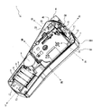
- FIG. 1 is a perspective view illustrating an overall configuration of a print label producing apparatus according to an embodiment of the present invention. It is a perspective view showing the internal structure of the print label producing apparatus in a state where the detachable cover is removed and the cartridge and the dry battery are mounted in the cartridge holder and the battery storage unit. It is a perspective view showing the internal structure of the print label producing apparatus in a state where the detachable cover is removed and the cartridge and the dry battery are removed from the cartridge holder and the battery storage unit. It is a top view showing the internal structure of a cartridge with a roller holder, a rib, a heat sink, a thermal head, etc. It is a perspective view showing the front surface of a detachable cover.
- FIG. 4 is a diagram illustrating a state where the tip of the cutter blade is in contact with a cutter blade receiving member. It is explanatory drawing explaining the half cutting operation
- FIG. 14 is a cross-sectional view taken along a line PP ′ in FIG. 13 and a cross-sectional view taken along a line QQ ′. It is a conceptual sectional view showing the behavior which performs desired cutting using the 1st cutter blade receiving part in the modification which leaves only the tape width direction both ends and cuts only the center side. It is the upper side figure and bottom view showing the external appearance of an example of the printed label continuous body formed by completing the desired cutting by the first cutter blade receiving part and the entire cutting by the second cutter blade receiving part. It is a conceptual sectional view showing the behavior which performs desired cutting using the 1st cutter blade receiving part in the modification which leaves only the tape width direction center side and cuts only both ends.
- the print label producing apparatus 1 is a handy type print label producing apparatus held by an operator's hand.
- the casing 6 of the print label producing apparatus 1 is composed of a front cover 6A that constitutes the front face of the apparatus and a rear cover 6B that constitutes the rear face of the apparatus.
- the rear cover 6B includes a rear cover body 6B1 incorporating various mechanisms, and a detachable cover 6B2 that can be detached from the rear cover body 6B1 when the cartridge 31 and the dry battery 8 (see FIG. 2 described later) are attached and detached. It consists of
- a liquid crystal display unit (not shown) for displaying print data, a setting screen, and the like is provided on the upper side of the front cover 6A.
- the front surface of the liquid crystal display unit is covered with a cover panel 2A made of, for example, a transparent acrylic plate.
- a keyboard unit 3 for operating the print label producing apparatus 1 is provided below the liquid crystal display unit.
- the keyboard unit 3 includes character keys such as characters, symbols and numbers, and various function keys.
- a cut lever 4 (operating lever) for cutting the printed label tape 80 (see FIG. 4 described later) is provided at the upper right side of the rear cover body 6B1.
- a frame 13 formed of resin is disposed inside the front cover 6A and the rear cover body 6B1.
- the cartridge holder 7 having a rectangular shape in plan view formed in a concave shape for attaching and detaching the cartridge 31 is provided on the upper rear side of the frame 13.
- a motor storage 5 for storing a motor (not shown).
- the battery storage unit 9 for storing the dry batteries 8 is provided further below the motor storage unit 5.
- a tape discharge slit 24 for discharging the printed label tape 80 (see FIG. 4 described later) to the outside is formed on the upper portion of the frame 13.
- a roller holder 17 (detailed structure will be described later) is provided on the upper right side of the frame 13.
- a plate portion 25 made of synthetic resin having a plate shape is provided so as to cover the roller holder 17.
- the plate portion 25 is formed integrally with the frame 13.
- a protrusion insertion port 10 that is an opening is provided on the upper portion of the plate portion 25.
- a lock hole 11 is provided at the upper end of the rear cover body 6B1, and two lock holes 12 are provided at the lower end.
- a gear recess 26 formed in a concave shape is provided at a substantially central portion of the frame 13.
- the gear recess 26 is provided with a gear (not shown), and the gear tooth portion is covered with the concealing umbrella portion 114 and is not exposed.
- a ribbon take-up shaft 14 for taking up an ink ribbon 55 is provided upright on the rear side of the gear.
- the gears and a plurality of gears (not shown) provided on the front side of the frame 13 meshing with the gears are each formed of a synthetic resin, and a gear shaft (not shown) that rotatably supports these gears. ) Is also formed of a synthetic resin, and is formed integrally with the frame 13.
- a rib 30 is erected on the right side of the ribbon take-up shaft 14.
- a heat sink 15 which is a rectangular heat sink is provided on the right side surface of the rib 30.
- a roller shaft 20 is erected between the rib 30 and the tape discharge slit 24.
- the roller shaft 20 is made of synthetic resin and is formed integrally with the frame 13.
- a convex portion 27 is erected on the left side of the roller shaft 20. The convex portion 27 is inserted into a concave portion (not shown) of the cartridge 31 to position the cartridge 31 in the front-rear direction.
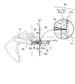
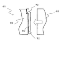
- a guide holder 40 that houses a cutter holder 60 (see FIG. 5 to be described later) having a cutter blade 63 (see FIG. 11 to be described later) is provided in the frame 13 in the vicinity of the tape discharge slit 24. Yes. Further, a cutter blade receiving member 41 is provided on the left side of the guide holder 40 in the vicinity of the tape discharge slit 24 in the frame 13. The cutter blade receiving member 41 is for receiving the cutter blade 63 when the printed label tape 80 is cut by the cutter blade 63.
- the cut lever 4 is supported so as to be rotatable with respect to the frame 13 (with a lever shaft 65 described later as an axis), and the cutter blade 63 can be moved.
- the first rib rib 42 and the holding portion 76 are integrally formed with the frame 13 in the vicinity of the tape discharge slit 24.
- the rib 42 formed on the right side of the tape discharge slit 24 is erected vertically with respect to the planar rear surface portion 25A of the plate portion 25.
- the holding portion 76 formed on the left side of the tape discharge slit 24 is erected on the left side of the cutter blade receiving member 41 and holds (attaches) the cutter blade receiving member 41.
- a cover film spool 52 around which a transparent film-like cover film 51 is wound is rotatably arranged at the lower left side in the cartridge case 33.
- the cover film 51 fed out from the cover film spool 52 is guided toward the cartridge opening 371 and sent out from the cartridge opening 371.
- a ribbon spool 56 around which an ink ribbon 55 is wound is rotatably arranged at the lower right side in the cartridge case 33.
- the ink ribbon 55 fed out from the ribbon spool 56 is guided toward the cartridge opening 371 and delivered together with the cover film 51.
- a ribbon take-up spool 57 is rotatably arranged between the cover film spool 52 and the ribbon spool 56.
- the ribbon take-up spool 57 pulls out the ink ribbon 55 from the ribbon spool 56 and winds up the ink ribbon 55 consumed by printing (printing) characters or the like.
- a base tape spool 54 around which a base tape 53 is wound is rotatably disposed in the upper part of the cartridge case 33.
- the base tape 53 has a four-layer structure (see a partially enlarged view in FIG. 4), and extends from the side wound radially inward (lower side of the enlarged view) to the opposite side (upper side of the enlarged view).
- an adhesive layer 53a made of an appropriate adhesive
- a colored base film (base material layer) 53b made of PEL (polyethylene terephthalate)
- an adhesive layer (adhesive layer) 53c made of an appropriate adhesive
- release paper The release material layer 53d is laminated in the order of 53d.
- the base tape 53 fed out from the base tape spool 54 is guided toward the tape transport roller 39, and the base tape 53 and the printed cover film 51 are connected to the tape transport roller 39 and the pressure roller 192.
- the pressure-sensitive adhesive layer 53a is pressure-bonded to form a printed label tape 80, which is conveyed toward the label tape discharge port 59.
- an arm-shaped roller holder 17 having a platen roller unit 18 and a pressing roller unit 19 can swing in the left-right direction around the shaft support portion 171.
- the roller holder 17 is also made of a synthetic resin like the frame 13.
- the platen roller unit 18 is disposed on the right side of the heat sink 15.
- the platen roller unit 18 is provided with a platen roller 182 and a platen roller gear (not shown).
- the platen roller 182 is disposed at a position facing the thermal head 16 provided on the right side surface of the heat sink 15.
- the thermal head 16 performs desired printing on the cover film 51 transported along the transport path by the pressing roller 192, the platen roller 182 and the like.
- the platen roller gear is meshed with a gear (not shown) provided on the front side of the frame 13, and the platen roller gear 182 is rotated by the rotation of the platen roller gear to which power is transmitted from the motor.
- the platen roller 182 presses the cover film 51 and the ink ribbon 55 against the thermal head 16, and characters, figures, symbols, etc. are printed.
- the cover film 51 is conveyed in the direction of the pressing roller unit 19 by its rotation.
- the pressing roller unit 19 is provided with a pressing roller 192 and a pressing roller gear (not shown).
- the pressing roller 192 is disposed at a position facing the roller shaft 20, and the transport path (arrows A, I) for the cover film 51, the base tape 53, and the printed label tape 80 to the tape discharge slit 24. , See c).
- the roller shaft 20 includes a cylindrical portion 201 formed in a cylindrical shape and six ribs 202 formed radially from the outer periphery of the cylindrical portion 201 to the outside.
- the roller shaft 20 is inserted into a shaft hole 391 of a tape transport roller 39 provided in the cartridge 31, and rotatably supports the tape transport roller 39.
- the pressure roller gear meshes with a gear (not shown) provided on the front side of the frame 13, and the pressure roller 192 is rotated by rotation of the pressure roller gear to which power is transmitted from the motor. .
- the pressing roller unit 19 moves to the printing position, the pressing roller 192 presses the cover film 51 and the base tape 53 against the tape transport roller 39 that is rotatably supported by the roller shaft 20. To do.
- the printed cover film 51 and the base tape 53 are pressure-bonded to form a printed label tape 80, which is discharged from the label tape discharge port 59.
- the transport path of the printed label tape 80 (in other words, the transport path of the cover film 51; the same applies hereinafter) is performed by the pressure roller 192 and the guide holder 40 and the cutter blade receiving member 41 (see FIG. 2 and the like).
- the cutter blade 63 cuts the printed label tape 80 (or semi-cuts, details will be described later).
- the cutter blade 63 moves in a direction (C direction in FIG. 11 to be described later) orthogonal to the conveyance path, and the cutter blade receiving member 41 mounted on the holding unit 76. The cutting (or semi-cutting) is performed by being received by.
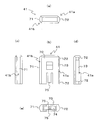
- the detachable cover 6B2 will be described with reference to FIG.
- the above-described lock member 47 is erected at the upper left end portion of the front surface 6a of the detachable cover 6B2, and the above-described two lock members 48 are erected at the lower end portion.
- the lock members 47 and 48 are fitted in the lock holes 11 and 12 (see FIG. 2 and the like) provided in the rear cover body 6B1, respectively. Thereby, the natural opening of the detachable cover 6B2 is prevented.
- a protrusion 45 is erected perpendicularly to the front surface 6a of the detachable cover 6B2 on the upper right side of the front surface 6a of the detachable cover 6B2.
- the protrusion 45 is inserted into and extracted from the protrusion insertion port 10 (see FIG. 2 and the like) provided in the rear cover body 6B1.
- the roller holder 17 can be moved to the printing position (position shown in FIG. 4) or moved to the standby position (position shown in FIG. 3).
- the protrusion 45 has a rib 42 (which is formed integrally with the frame 13) in a state where the detachable cover 6B2 is attached to the rear cover body 6B1 (in other words, a state where it is attached to the frame 13, the same applies hereinafter). 3) can be supported from the right side of the rib 42.
- a support rib 46 is erected vertically on the front surface 6a of the detachable cover 6B2 so as to be perpendicular to the front surface 6a of the detachable cover 6B2.
- the support rib 46 can support the holding portion 76 (see FIG. 3) formed integrally with the frame 13 from the left side of the holding portion 76 in a state where the detachable cover 6B2 is attached to the rear cover body 6B1. It has become. Note that the support rib 46 may be omitted when the holding portion 76 can sufficiently tolerate a reaction force from the printed label tape 80 during full cutting or half cutting (described later).
- the printed label is obtained by mounting one common cutter blade receiving member 41 having different shapes on one side and the other side to the holding portion 76 while changing the direction. Both normal full cutting and half cutting (described later) can be performed on the tape 80 for use. Hereinafter, the details will be described in order.
- a rectangular plate-like holding portion 76 is erected (integrated with the frame 13).
- the cutter blade receiving member 41 is formed in a square bag shape in this example, and the holding portion 76 (see FIG. 7) is inserted through the insertion hole 74 formed in the bottom. 6) and is detachably fitted and held.
- a horizontally-long rectangular locking hole 76A (see FIG. 6) is provided through both front and rear surfaces of the holding portion 76.
- the cutter blade receiving member 41 has elastic hook pieces 75 (lower and lower front and rear edges of the insertion hole 74) projecting so as to face each other on the insertion hole 74 side of the cutter blade receiving member 41 so as to correspond to the locking hole 76A. (See FIG. 7 (a) and FIG. 7 (b)). Accordingly, for example, when the operator holds the side blade 70 and fits the cutter blade receiving member 41 to the holding portion 76, the pair of front and rear elastic hook pieces 75 on the insertion hole 74 side of the cutter blade receiving member 41. Is engaged and held in the locking hole 76A of the holding portion 76.
- the tip of the elastic hook piece 75 rides on the wall surface, and the elastic hook piece 75 expands elastically. As a result, the cutter blade receiving member 41 is detached from the holding portion 76.
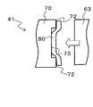
- the cutter blade receiving member 41 includes the first cutter blade receiving portion 41a on one side (the left rear side in FIG. 7A and the right front side in FIG. 7B) and the other side ( It is configured as one common cutter blade receiving member provided with a second cutter blade receiving portion 41b on the right front side in FIG. 7A and the left rear side in FIG. 7B.
- the cutter blade receiving member 41 is mounted on the holding portion 76 so that the first cutter blade receiving portion 41a side faces the transport path of the printed label tape 80 (see FIG. 7B and FIG. 12 described later). Or attached to the holding portion 76 so that the second cutter blade receiving portion 41b side faces the transport path of the printed label tape 80 (FIG. 7 (a) and FIGS. 11 (a) to 11 (to be described later)). (See (c)).
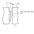
- the second cutter blade receiving portion 41 b includes a second contact portion 71.
- the second contact portion 71 is made of resin.
- the printed label tape 80 the cover film 51, the adhesive layer 53a, the base
- the contact of the cutting edge of the cutter blade 63 is received while sandwiching the entire tape width of the film 53b, the adhesive layer 53c, and the release paper 53d).
- the cutter blade 63 can completely cut the printed label tape 80 in the thickness direction.
- the first cutter blade receiving portion 41 a includes a recess 73 and two first contact portions 72.
- the recess 73 receives the entire tape width of the cover film 51 in the tape thickness direction.
- the 1st contact part 72 is comprised with the metal in this example, is provided in the both-sides adjacent position of the recessed part 73 along the tape width direction, and receives the blade edge
- the cutter blade 63 does not reach the cutting edge sufficiently to the entire dimension in the thickness direction of the printed label tape 80 received in the concave portion 63 of the cover film 51, and as a result, the cutter blade 63 partially in the thickness direction. It will cut
- the depth direction dimension d of the recess 73 is set in advance to be equal to the thickness direction dimension t of the release paper 53d.
- the cutter blade 63 can cut other portions (the cover film 51, the adhesive layer 53a, the base film 53b, and the adhesive layer 53c) of the printed label tape 80 while leaving the release paper 53d. .
- the setting of the depth direction dimension d of the recessed part 73 is not restricted above. It may be smaller than the dimension t in the thickness direction of the release paper 53d. In that case, a part of the dimension in the thickness direction can be cut also about the release paper 53d. Conversely, it may be larger than the thickness direction dimension t of the release paper 53d. In that case, by setting the dimension d in the depth direction, the remaining layers of the printed label tape 80, that is, up to which layer of the cover film 51, the adhesive layer 53a, the base film 53b, and the adhesive layer 53c are cut, Which layer is left (uncut) can be appropriately set to a desired mode.
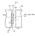
- FIGS. 11A to 11C show the cutter button 4, the guide holder 40, and the cutter blade receiving member 41 in the vicinity of the tape discharge slit 24 in a state where the removable cover 6B2 is removed from the print label producing apparatus 1. Corresponds to a view seen through from the rear side.
- the operator when performing full cutting, as described above, the operator can attach the second cutter blade receiving portion 41b to the printed label tape 80.
- the cutter blade receiving member 41 is attached to the holding portion 76 so as to be on the conveyance path side.
- the cut lever 4 is supported so as to be rotatable with respect to the frame 13 about a lever shaft 65 formed on the frame 13.
- the printed label tape 80 discharged from the label tape discharge port 59 (see FIG. 4) is guided along the conveyance path by the pressing roller 192 (see FIG. 4) or the like.
- the cutter blade receiving member 41 are conveyed from the bottom to the top. Then, it is guided to the tape discharge slit 24 and discharged (a part thereof) from the tape discharge slit 24 to the outside of the print label producing apparatus 1 to be in the state shown in FIG.
- the cut lever 4 is in the initial position (the position shown in FIG. 11A). Located in. When located at this initial position, the contact portion 4 ⁇ / b> A of the cut lever 4 is separated from the contact convex portion 62.
- the cut lever 4 rotates in the lever rotation direction R about the lever shaft 65.
- the contact portion 4A of the cut lever 4 contacts the contact convex portion 62.
- the contact portion 4A causes the cutter holder 60 to be attached to the printed label tape 80 via the contact convex portion 62 that is in contact. Is moved in the direction of arrow C (leftward) perpendicular to the transport path.
- the cutter blade 63 also moves in the direction of arrow C.
- the direction of the arrow C corresponds to the “direction perpendicular to the transport path” described in each claim.
- the cutter blade 63 gradually presses the printed label tape 80 and finally comes into contact with the cutter blade receiving member 41 (the state shown in FIG. 11C).
- the cutter blade 63 completely removes the printed label tape 80 over the entire thickness direction by the pressing force generated between the cutter blade 63 and the cutter blade receiving member 41 based on the turning operation of the cut lever 4. It can be pushed out (see FIG. 9).
- the printed label tape 80 received and entered into the concave portion 73 is shifted to the front side in the traveling direction as viewed from the cutter blade 63.
- the front end of the cutter blade 63 is printed at a timing later than that at the time of full cutting in FIGS. 11A to 11C (in other words, with a larger amount of operation of the cut lever 4 than at the time of full cutting).
- the cutter blade 63 gradually pushes the printed label tape 80 in contact with the tape 80 for printing.
- the cutter blade 63 comes into contact with the first contact portion 72 of the first cutter blade receiving portion 41a.
- the cutter blade 63 is a portion of the printed label tape 80 excluding the release paper 53, that is, the cover film 51 and the adhesive layer 53a, by the pressing force generated between the cutter blade 63 and the cutter blade receiving member 41.
- the base film 53b and the adhesive layer 53c are pushed all over the thickness direction (see FIG. 10).
- the cutter blade receiving member 41 has a fixed structure at any point in the cutting operation when the printed label tape 80 is completely cut and half cut by the cutter blade 63 due to the locking structure to the holding portion 76 described above. It rarely moves from position.
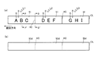
- Print label L An example of the print label L created by the operator while changing the orientation of the cutter blade receiving member 41 as described above will be described with reference to FIGS. 13 and 14.
- a print label continuous body including three print labels L1, L2, and L2 is created.
- These printed labels L1, L2, and L3 are formed by completing the cutting or semi-cutting of the printed label tape 80 as described above, and the cover film has the four-layer structure shown in FIG. A five-layer structure with 51 added (see FIG. 14A). That is, from the cover film 51 side (upper side in FIG. 14A) toward the opposite side (lower side in FIG. 14A), the cover film 51, the adhesive layer 53a, the base film 53b, the adhesive layer 53c, and the peeling The paper 53d constitutes five layers. And the printing R is printed on the back surface of the cover film 51, respectively.
- the cutter blade receiving member 41 is mounted so that the first cutter blade receiving portion 41a is on the conveyance path side of the printed label tape 80, and the cutter blade 63 is half-finished.
- a print label L1 having a print R of “ABC” and a print label L2 having a print R of “DEF” are created.
- the rear end portion in other words, the boundary portion with the print label L2 on the upstream side in the conveyance direction of the print label L1 (in other words, the boundary portion with the print label L2) is the release paper 53 of the printed label tape 80 which is the result of the half-cut.
- cover film 51, the adhesive layer 53a, the base film 53b, and the adhesive layer 53c are divided into half cut portions HC (see FIG. 14B).
- the cutter blade receiving member 41 is replaced so that the second cutter blade receiving portion 41b is on the side of the transport path of the printed label tape 80, and the cutter blade 63 performs a half-cut state as “GHI”.
- a print label L3 having a print R of "" is created.
- the rear end portion on the upstream side in the transport direction of the print label L3 (in other words, the rear end portion of the print label continuous body) is divided by all the layers of the printed label tape 80, which is the result of the above-described complete cutting.
- the full cut line CL is made.
- the printed label tape 80 is cut to a predetermined length by the cooperation of the cutter blade 63 and the cutter blade receiving member 41.
- a print label L having a desired print R is created.
- the cutter blade receiving member 41 is configured to be detachable from the holding portion 63.
- the printed label tape 80 can be completely cut. it can.
- the cutter blade receiving member 41 By attaching the cutter blade receiving member 41 to the holding portion 63 so that the first cutter blade receiving portion 41a faces the conveyance path side of the printed label tape 80, the printed label tape 80 can be cut in half. it can. That is, by simply changing the cutter blade receiving member 41 attached to the holding portion 76 in the opposite direction, both the full cutting and the desired cutting (half cutting in this example) are performed using the same one cutter blade 63. Can be executed. Thereby, compared with the conventional structure which needed to install both the cutting device for full cutting, and the cutting device for desired cutting, size reduction of a device and reduction of manufacturing cost can be aimed at.
- the cutting mode can be switched simply by changing the direction of the common one cutter blade receiving member 41. Therefore, the cutter blade receiving member and the second cutter corresponding to the first cutter blade receiving portion 41a are switched. The number of parts can be reduced and the handleability can be improved as compared with the case where two cutter blade receiving members corresponding to the blade receiving portion 41b are prepared separately (see modification (4) described later).
- the first contact portion 72 of the first cutter blade receiving portion 41a is made of metal, wear of the first contact portion 72 that may occur when made of resin or the like is avoided. be able to. However, in this case, due to the reception of the cutting edge by the first contact portion 72, wear of the portion of the cutting edge of the cutter blade 63 that is received by the first contact portion 72 occurs. However, as described above, since the first contact portion 72 is provided on both sides in the tape width direction with respect to the concave portion 73 that receives the entire width of the printed label tape 80, the wear of the cutting edge of the cutter blade 63 occurs. The resulting portion is a portion that does not contribute to the total cutting of the printed label tape 80 in the thickness direction.
- the second contact portion 71 is made of resin, the cutting edge of the cutter blade 63 is rarely damaged during the entire cutting. As a result, wear of the first cutting blade receiving member can be avoided while securing the cutting performance of the cutter blade 63.
- the first cutter blade receiving portion 41 a has one central first contact portion. 72 and two concave portions 73 on both sides in the tape width direction adjacent to both sides of the first contact portion 72 in the tape width direction.
- the recess 73 receives a part of the entire tape width of the printed label tape 80 (both ends in the tape width direction in this example) in the tape thickness direction. Further, the depth direction dimension of the recess 73 is equal to (or deeper than) the thickness direction dimension of the printed label tape 80 in this example.
- the cutting edge of the cutter blade 63 is placed in the recess 73 of the printed label tape 80. It does not reach the position where it is located and is not cut (see FIG. 16).
- the first contact portion 72 receives the cutting edge of the cutter blade 63 in the same manner as described above, so that the cutter blade 63 has a portion in the thickness direction corresponding to the first contact portion 72 in the printed label tape 80. Cut all into.
- the cutter blade receiving member 41 is mounted so that the first cutter blade receiving portion 41a is on the conveyance path side of the printed label tape 80, and the cutter blade 63 is A print label L1 having a print R of “ABC” and a print label L2 having a print R of “DEF” are created as states for performing desired cutting.
- the rear end portion in other words, the boundary portion with the print label L2 on the upstream side in the conveyance direction of the print label L1 (in other words, the boundary portion with the print label L2) is slit-like full only at the center side while leaving both ends in the tape width direction as a result of the desired cutting.
- the cut part FC is formed.
- the rear end portion on the upstream side in the transport direction of the print label L2 in other words, the boundary portion with the print label L3.
- the cutter blade receiving member 41 is replaced so that the second cutter blade receiving portion 41b is on the side of the transport path of the printed label tape 80, and the cutter blade 63 performs a half-cut state as “GHI”.
- a print label L3 having a print R of "" is created.
- the rear end portion on the upstream side in the transport direction of the print label L3 (in other words, the rear end portion of the print label continuous body) is divided by all the layers of the printed label tape 80, which is the result of the above-described complete cutting.
- the full cut line CL is made.
- the cutter blade receiving member 41 is attached to the holding portion 63 so that the second cutter blade receiving portion 41b faces the transport path side of the printed label tape 80, thereby cutting the printed label tape 80 completely. be able to. Further, by mounting the cutter blade receiving member 41 on the holding portion 63 so that the first cutter blade receiving portion 41a faces the conveyance path side of the printed label tape 80, the desired cutting of the printed label tape 80 can be performed. It can be carried out. That is, by simply changing the cutter blade receiving member 41 attached to the holding portion 76 in the reverse direction, all the cutting and desired cutting are performed using the same one cutter blade 63 (in this example, only the center side is cut while leaving both ends in the tape width direction). ) And both.
- the first cutter blade receiving portion 41a includes a central concave portion 73, Two first contact portions 72 on both sides in the tape width direction are provided on both sides of the recess 73 in the tape width direction.
- the concave portion 73 receives a part of the entire tape width of the printed label tape 80 (in this example, the central portion in the tape width direction) in the tape thickness direction.
- the depth dimension of the recess 73 is equal to (or deeper than) the dimension of the printed label tape 80 in the thickness direction as described above.
- the cutting edge of the cutter blade 63 is placed in the recess 73 of the printed label tape 80. It does not reach the position where it is located and is not cut (see FIG. 18).
- the first contact portion 72 receives the cutting edge of the cutter blade 63 in the same manner as described above, so that the cutter blade 63 corresponds to the portion of the printed label tape 80 corresponding to the first contact portion 72 (both ends in the tape width direction). Part) is cut in the thickness direction.
- the cutter blade receiving member 41 is mounted so that the first cutter blade receiving portion 41a is on the transport path side of the printed label tape 80, and the print R of "ABC” R and the print R of "DEF"
- the print labels L1 and L2 are prepared.
- the rear end portion (boundary portion with the print label L2) on the upstream side (right side in the drawing) of the print label L1 is slit-like full cut only at both ends, leaving the central side in the tape width direction as a result of the desired cutting.
- Part FC is formed. The same applies to the rear end portion on the upstream side in the transport direction of the print label L2 (in other words, the boundary portion with the print label L3).
- the desired cutting can be performed on the printed label tape 80 by mounting the cutter blade receiving member 41 so that the first cutter blade receiving portion 41a faces the conveyance path side. . Therefore, it is possible to perform both full cutting and desired cutting (in this example, cutting only both ends except for the central side in the tape width direction) using the same one cutter blade 63.
- the first cutter blade receiving portion 41 a is aligned with the tape width direction.
- One concave portion 73 corresponding to one side end portion and one first contact portion 72 adjacent to the other side of the concave portion 73 along the tape width direction are provided.
- the concave portion 73 receives a part of the entire tape width of the printed label tape 80 (one end portion in the tape width direction in this example) in the tape thickness direction.
- the depth dimension of the recess 73 is equal to (or deeper than) the dimension of the printed label tape 80 in the thickness direction as described above.
- the cutting edge of the cutter blade 63 is placed in the recess 73 of the printed label tape 80. It does not reach the position where it is positioned and is not cut (see FIG. 20).
- the first contact portion 72 receives the cutting edge of the cutter blade 63 in the same manner as described above, so that the cutter blade 63 corresponds to the portion of the printed label tape 80 corresponding to the first contact portion 72 (one in the tape width direction). For the part other than the side end part, the whole is cut in the thickness direction.
- the cutter blade receiving member 41 is mounted so that the first cutter blade receiving portion 41a is on the transport path side of the printed label tape 80, and the print R of "ABC” R and the print R of "DEF"
- the print labels L1 and L2 are prepared.
- the rear end portion (boundary portion with the print label L2) on the upstream side (the right side in the drawing) of the print label L1 is left as a slit-shaped full on the other side as a result of the desired cutting.
- the cut part FC is formed.
- the rear end portion on the upstream side in the transport direction of the print label L2 in other words, the boundary portion with the print label L3.
- the desired cutting can be performed on the printed label tape 80 by mounting the cutter blade receiving member 41 so that the first cutter blade receiving portion 41a faces the conveyance path side. . Therefore, it is possible to perform both full cutting and desired cutting (in this example, cutting the remaining part while leaving one end in the tape width direction) using the same one cutter blade 63.
- the present invention is not limited to this. That is, as shown in FIGS. 21A and 21B, the first cutter blade receiving member 41 ⁇ / b> A having the first contact portion 72 and the recess 73 and the second cutter blade having the second contact portion 71. Both the receiving member 41 ⁇ / b> B may be prepared, and these may be selectively mounted on the holding portion 63 and used.
- the second cutter blade receiving member 41B is attached to the holding portion 63 (so that the second contact portion 71 faces the transport path side of the printed label tape 80), so that the printed label can be used.
- the entire tape 80 can be cut.
- the printed label tape is mounted by attaching the first cutter blade receiving member 41A to the holding portion 63 (so that the first contact portion 72 and the recessed portion 73 face the transport path side of the printed label tape 80).
- 80 half cuts can be made. That is, by exchanging the cutter blade receiving members 41A and 41B attached to the holding portion 76, both full cutting and desired cutting (half cutting in this example) are performed using the same one cutter blade 63. Can be executed. Thereby, compared with the conventional structure which needed to install both the cutting device for full cutting, and the cutting device for desired cutting, size reduction of a device and reduction of manufacturing cost can be aimed at.
- the cutter blade receiving member 41 ′ which is not attached to the holding portion 76 can be locked.
- a locking portion 76 ' may be provided at an appropriate location (see the imaginary line in FIG. 3).
- the locking portion 76 ′ in FIG. 3 is an example provided on the frame 13. In this way, by providing a storage place for the cutter blade receiving member 41 ′ that is not used by being mounted on the holding portion 76, the cutter blade receiving member 41 ′ is prevented from being lost and integrated with the main body of the print label producing apparatus 1. Has the effect of improving the ease of handling.
- the method is to print on the cover film 51 different from the base tape 53 and bond them together.
- the present invention is not limited to this, and the print-receiving tape layer provided in the base tape
- the present invention may be applied to a method for performing printing (a type in which bonding is not performed).
Landscapes
- Life Sciences & Earth Sciences (AREA)
- Forests & Forestry (AREA)
- Engineering & Computer Science (AREA)
- Mechanical Engineering (AREA)
- Handling Of Sheets (AREA)
- Nonmetal Cutting Devices (AREA)
Abstract
L'objet de la présente invention est d'obtenir à la fois une coupe complète d'une bande devant être imprimée et toute autre forme de coupe souhaitée sans augmenter la taille du dispositif ou sans augmenter les coûts de fabrication. La présente invention a trait à un dispositif qui est équipé d'un ensemble dispositif de création d'étiquette d'impression et d'un élément de réception de couteau (41). L'ensemble dispositif de création d'étiquette d'impression comprend un rouleau de transport de bande (39), un rouleau presseur (192), une tête thermique (16), un couteau (63) qui se déplace dans une direction (C) orthogonale à une trajectoire de transport et une partie de support (73). L'élément de réception de couteau (41) est en mesure de recevoir le couteau (63). L'élément de réception de couteau (41) inclut : une première partie de réception de couteau (41a) comprenant une concavité (73) dans laquelle au moins une partie de la largeur de bande complète de la bande d'étiquette imprimée (80) peut être ajustée dans la direction de l'épaisseur de bande et d'une première partie de contact (72) permettant d'entrer en contact avec le bord de lame du couteau (63) ; et d'une seconde partie de réception de couteau (41b) comprenant une seconde partie de contact (71) permettant d'envelopper la largeur de bande complète de la bande d'étiquette imprimée (80) et d'entrer en contact avec le bord de lame du couteau (63).
Priority Applications (1)
| Application Number | Priority Date | Filing Date | Title |
|---|---|---|---|
| JP2013507539A JP5945978B2 (ja) | 2011-03-28 | 2012-03-23 | 印字ラベル作成装置及び切断刃受け部材 |
Applications Claiming Priority (2)
| Application Number | Priority Date | Filing Date | Title |
|---|---|---|---|
| JP2011069420 | 2011-03-28 | ||
| JP2011-069420 | 2011-03-28 |
Publications (1)
| Publication Number | Publication Date |
|---|---|
| WO2012133247A1 true WO2012133247A1 (fr) | 2012-10-04 |
Family
ID=46930969
Family Applications (1)
| Application Number | Title | Priority Date | Filing Date |
|---|---|---|---|
| PCT/JP2012/057637 Ceased WO2012133247A1 (fr) | 2011-03-28 | 2012-03-23 | Dispositif de création d'étiquette d'impression et élément de réception de couteau |
Country Status (3)
| Country | Link |
|---|---|
| US (1) | US9145009B2 (fr) |
| JP (1) | JP5945978B2 (fr) |
| WO (1) | WO2012133247A1 (fr) |
Cited By (5)
| Publication number | Priority date | Publication date | Assignee | Title |
|---|---|---|---|---|
| JP2018171697A (ja) * | 2017-03-31 | 2018-11-08 | ブラザー工業株式会社 | 切込装置 |
| JP2021007995A (ja) * | 2019-06-28 | 2021-01-28 | ブラザー工業株式会社 | 切断装置、及び印刷装置 |
| US11376874B2 (en) | 2017-06-22 | 2022-07-05 | Seiko Epson Corporation | Half cutter, method of manufacturing half cutter, and tape printing device |
| JP7581809B2 (ja) | 2020-12-04 | 2024-11-13 | ブラザー工業株式会社 | 切断装置、及び印刷装置 |
| US20250100302A1 (en) * | 2023-09-22 | 2025-03-27 | Toshiba Tec Kabushiki Kaisha | Printer |
Families Citing this family (5)
| Publication number | Priority date | Publication date | Assignee | Title |
|---|---|---|---|---|
| EP3075499B1 (fr) * | 2015-03-31 | 2017-11-08 | Brother Kogyo Kabushiki Kaisha | Dispositif de découpe et imprimante |
| JP6299647B2 (ja) * | 2015-03-31 | 2018-03-28 | ブラザー工業株式会社 | 切断装置及び印刷装置 |
| JP6369412B2 (ja) * | 2015-07-24 | 2018-08-08 | ブラザー工業株式会社 | 切断装置、及び印刷装置 |
| JP6699288B2 (ja) * | 2016-03-28 | 2020-05-27 | セイコーエプソン株式会社 | 切断装置およびこれを備えた印刷装置 |
| JP2025057050A (ja) * | 2023-09-28 | 2025-04-09 | ブラザー工業株式会社 | 切断装置及び印刷装置 |
Citations (4)
| Publication number | Priority date | Publication date | Assignee | Title |
|---|---|---|---|---|
| JPH04141466A (ja) * | 1990-10-03 | 1992-05-14 | Brother Ind Ltd | テープの端部処理装置 |
| JPH11170638A (ja) * | 1997-12-15 | 1999-06-29 | Brother Ind Ltd | テーププリンタにおける部分カット装置 |
| JPH11277820A (ja) * | 1998-03-27 | 1999-10-12 | Brother Ind Ltd | テーププリンタの切断装置 |
| JP2005096103A (ja) * | 2003-09-22 | 2005-04-14 | Brother Ind Ltd | テープ印刷装置 |
Family Cites Families (13)
| Publication number | Priority date | Publication date | Assignee | Title |
|---|---|---|---|---|
| USRE32490E (en) * | 1971-06-23 | 1987-09-01 | Monarch Marking Systems, Inc. | Method of making a composite label web |
| US5458423A (en) * | 1992-06-11 | 1995-10-17 | Esselte Dymo N.V. | Tape cutting apparatus |
| US5813305A (en) * | 1995-01-06 | 1998-09-29 | Intermec Corporation | Strip cutter for adhesive-backed media |
| JP3644152B2 (ja) * | 1996-09-26 | 2005-04-27 | ブラザー工業株式会社 | テープ印字装置 |
| JP3899656B2 (ja) * | 1998-03-31 | 2007-03-28 | ブラザー工業株式会社 | テーププリンタ |
| JP2000000797A (ja) * | 1998-04-17 | 2000-01-07 | Brother Ind Ltd | 裁断用カッタの昇降調節装置 |
| JP4452392B2 (ja) * | 2000-09-29 | 2010-04-21 | セイコーエプソン株式会社 | テープ印刷装置 |
| JP3722117B2 (ja) * | 2002-12-20 | 2005-11-30 | ブラザー工業株式会社 | テープ印字装置 |
| US20050061132A1 (en) * | 2003-08-19 | 2005-03-24 | Seiko Epson Corporation | Cutter unit, half-cutting mechanism, and tape printer |
| MX2007006385A (es) * | 2004-11-30 | 2007-06-20 | Panduit Corp | Cortador de material con perfil seleccionable de corte. |
| GB0706785D0 (en) * | 2007-04-05 | 2007-05-16 | Dymo Nv | Tape printing apparatus |
| JP4735723B2 (ja) * | 2009-01-30 | 2011-07-27 | ブラザー工業株式会社 | テープ印刷装置 |
| JP2010211634A (ja) | 2009-03-11 | 2010-09-24 | Brother Ind Ltd | 印字ラベル作成装置 |
-
2012
- 2012-03-23 WO PCT/JP2012/057637 patent/WO2012133247A1/fr not_active Ceased
- 2012-03-23 JP JP2013507539A patent/JP5945978B2/ja active Active
-
2013
- 2013-06-27 US US13/929,339 patent/US9145009B2/en active Active
Patent Citations (4)
| Publication number | Priority date | Publication date | Assignee | Title |
|---|---|---|---|---|
| JPH04141466A (ja) * | 1990-10-03 | 1992-05-14 | Brother Ind Ltd | テープの端部処理装置 |
| JPH11170638A (ja) * | 1997-12-15 | 1999-06-29 | Brother Ind Ltd | テーププリンタにおける部分カット装置 |
| JPH11277820A (ja) * | 1998-03-27 | 1999-10-12 | Brother Ind Ltd | テーププリンタの切断装置 |
| JP2005096103A (ja) * | 2003-09-22 | 2005-04-14 | Brother Ind Ltd | テープ印刷装置 |
Cited By (7)
| Publication number | Priority date | Publication date | Assignee | Title |
|---|---|---|---|---|
| JP2018171697A (ja) * | 2017-03-31 | 2018-11-08 | ブラザー工業株式会社 | 切込装置 |
| US11883972B2 (en) | 2017-03-31 | 2024-01-30 | Brother Kogyo Kabushiki Kaisha | Slit-cutting device |
| US11376874B2 (en) | 2017-06-22 | 2022-07-05 | Seiko Epson Corporation | Half cutter, method of manufacturing half cutter, and tape printing device |
| JP2021007995A (ja) * | 2019-06-28 | 2021-01-28 | ブラザー工業株式会社 | 切断装置、及び印刷装置 |
| JP7346940B2 (ja) | 2019-06-28 | 2023-09-20 | ブラザー工業株式会社 | 切断装置、及び印刷装置 |
| JP7581809B2 (ja) | 2020-12-04 | 2024-11-13 | ブラザー工業株式会社 | 切断装置、及び印刷装置 |
| US20250100302A1 (en) * | 2023-09-22 | 2025-03-27 | Toshiba Tec Kabushiki Kaisha | Printer |
Also Published As
| Publication number | Publication date |
|---|---|
| US9145009B2 (en) | 2015-09-29 |
| JPWO2012133247A1 (ja) | 2014-07-28 |
| JP5945978B2 (ja) | 2016-07-05 |
| US20130287467A1 (en) | 2013-10-31 |
Similar Documents
| Publication | Publication Date | Title |
|---|---|---|
| JP5945978B2 (ja) | 印字ラベル作成装置及び切断刃受け部材 | |
| US8366264B2 (en) | Handheld type print label producing apparatus | |
| JPWO2010113365A1 (ja) | テープカセット | |
| JP2009214431A (ja) | テープカセット | |
| JP6988135B2 (ja) | 印刷装置 | |
| JP5327711B2 (ja) | 印字ラベル作成装置 | |
| JP6825455B2 (ja) | 印刷装置 | |
| JP5267292B2 (ja) | 印刷装置 | |
| JP2009202546A (ja) | テープ印字装置 | |
| JP2022089306A (ja) | 切断装置、及び印刷装置 | |
| US12202257B2 (en) | Printing cassette | |
| JP2019045645A (ja) | テープ、テープロール及びテープカセット | |
| JP2014201649A (ja) | 基材テープロール及びテープカセット | |
| JP2007286462A (ja) | プリンター用ラベル連続体およびその製造方法 | |
| JP2009090497A (ja) | テープカセット及びテープ印字装置 | |
| JP2019043017A (ja) | テープ、テープロール、及びテープカセット | |
| JP2009090506A (ja) | テープカセット及びテープ印字装置 | |
| JP2011121140A (ja) | カット装置及びこれを備えたテープ印刷装置 | |
| JP2004026363A (ja) | ラベルライター用テープ及びこれが収納されるテープカセット | |
| JP4983833B2 (ja) | 印刷装置 | |
| US20190001714A1 (en) | Label Medium and Cassette | |
| JP2010100377A (ja) | テープカセット | |
| JP2019159004A (ja) | テープおよびテープカセット | |
| JP2012096366A (ja) | ハーフカット機構、カッターユニット、およびテープ印刷装置 | |
| JP6922817B2 (ja) | テープ、テープロール、テープカセット、及び複数の媒体を貼り合わせる方法 |
Legal Events
| Date | Code | Title | Description |
|---|---|---|---|
| 121 | Ep: the epo has been informed by wipo that ep was designated in this application |
Ref document number: 12764635 Country of ref document: EP Kind code of ref document: A1 |
|
| ENP | Entry into the national phase |
Ref document number: 2013507539 Country of ref document: JP Kind code of ref document: A |
|
| NENP | Non-entry into the national phase |
Ref country code: DE |
|
| 122 | Ep: pct application non-entry in european phase |
Ref document number: 12764635 Country of ref document: EP Kind code of ref document: A1 |