WO2012133274A1 - 蓄電システム及び移動体 - Google Patents
蓄電システム及び移動体 Download PDFInfo
- Publication number
- WO2012133274A1 WO2012133274A1 PCT/JP2012/057701 JP2012057701W WO2012133274A1 WO 2012133274 A1 WO2012133274 A1 WO 2012133274A1 JP 2012057701 W JP2012057701 W JP 2012057701W WO 2012133274 A1 WO2012133274 A1 WO 2012133274A1
- Authority
- WO
- WIPO (PCT)
- Prior art keywords
- power
- power storage
- unit
- storage unit
- storage battery
- Prior art date
- Legal status (The legal status is an assumption and is not a legal conclusion. Google has not performed a legal analysis and makes no representation as to the accuracy of the status listed.)
- Ceased
Links
Images






Classifications
-
- H—ELECTRICITY
- H01—ELECTRIC ELEMENTS
- H01M—PROCESSES OR MEANS, e.g. BATTERIES, FOR THE DIRECT CONVERSION OF CHEMICAL ENERGY INTO ELECTRICAL ENERGY
- H01M10/00—Secondary cells; Manufacture thereof
- H01M10/42—Methods or arrangements for servicing or maintenance of secondary cells or secondary half-cells
- H01M10/425—Structural combination with electronic components, e.g. electronic circuits integrated to the outside of the casing
-
- H—ELECTRICITY
- H01—ELECTRIC ELEMENTS
- H01M—PROCESSES OR MEANS, e.g. BATTERIES, FOR THE DIRECT CONVERSION OF CHEMICAL ENERGY INTO ELECTRICAL ENERGY
- H01M10/00—Secondary cells; Manufacture thereof
- H01M10/42—Methods or arrangements for servicing or maintenance of secondary cells or secondary half-cells
- H01M10/44—Methods for charging or discharging
- H01M10/441—Methods for charging or discharging for several batteries or cells simultaneously or sequentially
-
- H—ELECTRICITY
- H01—ELECTRIC ELEMENTS
- H01M—PROCESSES OR MEANS, e.g. BATTERIES, FOR THE DIRECT CONVERSION OF CHEMICAL ENERGY INTO ELECTRICAL ENERGY
- H01M10/00—Secondary cells; Manufacture thereof
- H01M10/42—Methods or arrangements for servicing or maintenance of secondary cells or secondary half-cells
- H01M10/48—Accumulators combined with arrangements for measuring, testing or indicating the condition of cells, e.g. the level or density of the electrolyte
- H01M10/482—Accumulators combined with arrangements for measuring, testing or indicating the condition of cells, e.g. the level or density of the electrolyte for several batteries or cells simultaneously or sequentially
-
- H—ELECTRICITY
- H01—ELECTRIC ELEMENTS
- H01M—PROCESSES OR MEANS, e.g. BATTERIES, FOR THE DIRECT CONVERSION OF CHEMICAL ENERGY INTO ELECTRICAL ENERGY
- H01M10/00—Secondary cells; Manufacture thereof
- H01M10/42—Methods or arrangements for servicing or maintenance of secondary cells or secondary half-cells
- H01M10/48—Accumulators combined with arrangements for measuring, testing or indicating the condition of cells, e.g. the level or density of the electrolyte
- H01M10/486—Accumulators combined with arrangements for measuring, testing or indicating the condition of cells, e.g. the level or density of the electrolyte for measuring temperature
-
- H—ELECTRICITY
- H02—GENERATION; CONVERSION OR DISTRIBUTION OF ELECTRIC POWER
- H02J—ELECTRIC POWER NETWORKS; CIRCUIT ARRANGEMENTS OR SYSTEMS FOR SUPPLYING OR DISTRIBUTING ELECTRIC POWER; SYSTEMS FOR STORING ELECTRIC ENERGY
- H02J3/00—Circuit arrangements for AC mains or AC distribution networks
- H02J3/28—Arrangements for balancing of the load in networks by storage of energy
- H02J3/32—Arrangements for balancing of the load in networks by storage of energy using batteries or super capacitors with converting means
-
- H—ELECTRICITY
- H02—GENERATION; CONVERSION OR DISTRIBUTION OF ELECTRIC POWER
- H02J—ELECTRIC POWER NETWORKS; CIRCUIT ARRANGEMENTS OR SYSTEMS FOR SUPPLYING OR DISTRIBUTING ELECTRIC POWER; SYSTEMS FOR STORING ELECTRIC ENERGY
- H02J7/00—Circuit arrangements for charging or discharging batteries or for supplying loads from batteries
- H02J7/34—Parallel operation in networks using both storage and other DC sources, e.g. providing buffering
-
- H—ELECTRICITY
- H02—GENERATION; CONVERSION OR DISTRIBUTION OF ELECTRIC POWER
- H02J—ELECTRIC POWER NETWORKS; CIRCUIT ARRANGEMENTS OR SYSTEMS FOR SUPPLYING OR DISTRIBUTING ELECTRIC POWER; SYSTEMS FOR STORING ELECTRIC ENERGY
- H02J7/00—Circuit arrangements for charging or discharging batteries or for supplying loads from batteries
- H02J7/50—Circuit arrangements for charging or discharging batteries or for supplying loads from batteries acting upon multiple batteries simultaneously or sequentially
-
- H—ELECTRICITY
- H02—GENERATION; CONVERSION OR DISTRIBUTION OF ELECTRIC POWER
- H02J—ELECTRIC POWER NETWORKS; CIRCUIT ARRANGEMENTS OR SYSTEMS FOR SUPPLYING OR DISTRIBUTING ELECTRIC POWER; SYSTEMS FOR STORING ELECTRIC ENERGY
- H02J7/00—Circuit arrangements for charging or discharging batteries or for supplying loads from batteries
- H02J7/50—Circuit arrangements for charging or discharging batteries or for supplying loads from batteries acting upon multiple batteries simultaneously or sequentially
- H02J7/52—Circuit arrangements for charging or discharging batteries or for supplying loads from batteries acting upon multiple batteries simultaneously or sequentially for charge balancing, e.g. equalisation of charge between batteries
- H02J7/54—Passive balancing, e.g. using resistors or parallel MOSFETs
-
- H—ELECTRICITY
- H02—GENERATION; CONVERSION OR DISTRIBUTION OF ELECTRIC POWER
- H02J—ELECTRIC POWER NETWORKS; CIRCUIT ARRANGEMENTS OR SYSTEMS FOR SUPPLYING OR DISTRIBUTING ELECTRIC POWER; SYSTEMS FOR STORING ELECTRIC ENERGY
- H02J7/00—Circuit arrangements for charging or discharging batteries or for supplying loads from batteries
- H02J7/80—Circuit arrangements for charging or discharging batteries or for supplying loads from batteries including monitoring or indicating arrangements
- H02J7/82—Control of state of charge [SOC]
-
- H—ELECTRICITY
- H01—ELECTRIC ELEMENTS
- H01M—PROCESSES OR MEANS, e.g. BATTERIES, FOR THE DIRECT CONVERSION OF CHEMICAL ENERGY INTO ELECTRICAL ENERGY
- H01M2220/00—Batteries for particular applications
- H01M2220/20—Batteries in motive systems, e.g. vehicle, ship, plane
-
- Y—GENERAL TAGGING OF NEW TECHNOLOGICAL DEVELOPMENTS; GENERAL TAGGING OF CROSS-SECTIONAL TECHNOLOGIES SPANNING OVER SEVERAL SECTIONS OF THE IPC; TECHNICAL SUBJECTS COVERED BY FORMER USPC CROSS-REFERENCE ART COLLECTIONS [XRACs] AND DIGESTS
- Y02—TECHNOLOGIES OR APPLICATIONS FOR MITIGATION OR ADAPTATION AGAINST CLIMATE CHANGE
- Y02E—REDUCTION OF GREENHOUSE GAS [GHG] EMISSIONS, RELATED TO ENERGY GENERATION, TRANSMISSION OR DISTRIBUTION
- Y02E60/00—Enabling technologies; Technologies with a potential or indirect contribution to GHG emissions mitigation
- Y02E60/10—Energy storage using batteries
-
- Y—GENERAL TAGGING OF NEW TECHNOLOGICAL DEVELOPMENTS; GENERAL TAGGING OF CROSS-SECTIONAL TECHNOLOGIES SPANNING OVER SEVERAL SECTIONS OF THE IPC; TECHNICAL SUBJECTS COVERED BY FORMER USPC CROSS-REFERENCE ART COLLECTIONS [XRACs] AND DIGESTS
- Y02—TECHNOLOGIES OR APPLICATIONS FOR MITIGATION OR ADAPTATION AGAINST CLIMATE CHANGE
- Y02T—CLIMATE CHANGE MITIGATION TECHNOLOGIES RELATED TO TRANSPORTATION
- Y02T10/00—Road transport of goods or passengers
- Y02T10/60—Other road transportation technologies with climate change mitigation effect
- Y02T10/70—Energy storage systems for electromobility, e.g. batteries
Definitions
- the present invention relates to a power storage system and a moving object.
- the power consumption curve of the power demand curve as shown in FIG. 12 is supplemented by the discharge of the storage battery, and the system power consumption leveling due to effective use of late-night power and fluctuations in power consumption (peak cut) )It can be performed.
- the ratio of power supply by thermal power generation in which the CO2 emission is larger than in the time zone where the power consumption is small is increased, so that the CO2 emission can be reduced by leveling.
- the electricity charge for grid power includes a fixed basic charge and a pay-per-use charge.
- the electric power company makes the basic fee cheaper as the maximum value of the system power consumed per unit time becomes smaller, and the usage fee is lower during the night when the power consumption is lower than during the day when the power consumption is high.
- the usage fee is set so that the price per unit of electricity is reduced.
- the storage battery is charged using the system power in the time zone when the power demand of the user who uses the system power is small or the time when the late-night electricity rate is applied,
- the power charge of the grid power can be suppressed by supplementing the power for the amount exceeding the predetermined threshold with the discharge of the storage battery.
- Such a storage battery uses a storage battery such as a lithium ion battery, there is a problem in that the battery deteriorates when used for a long period of time and the battery capacity that can be charged and discharged decreases.
- Patent Document 1 as a management technique for a lithium ion battery, the state of charge / discharge of the lithium ion battery is determined based on the measured value of the charge / discharge current of the lithium ion battery, the measured value of the temperature, and the power supply information of the commercial power source.
- a technique for estimating the remaining capacity of a lithium ion battery is described.
- the storage system does not always know the capacity of the battery that can be charged or discharged, there is a risk that it will not be possible to charge / discharge the correct amount of power, and the intended power supply will not be possible.
- SOC current remaining battery capacity
- the SOC estimation method the relationship between the voltage and the remaining capacity is held as a table, and the remaining capacity with respect to the measured voltage is obtained by referring to the table.
- the capacity of the storage battery can be charged / discharged in order to estimate the accurate SOC because the battery capacity becomes inaccurate with the number of times of charging / discharging and the passage of time. Capacity learning (calibration) to store the latest data is required.
- Patent Document 2 describes a technique for performing capacity learning for a single battery in a short time, and increases the load on a device in which a storage battery is incorporated so as to quickly discharge when performing capacity learning.
- it has been proposed to shorten the time during which normal operation is hindered by shortening the time required for capacity learning by increasing the power consumption.
- such a method cannot eliminate a time zone during which normal operation cannot be performed. Accordingly, an object of the present invention is to perform capacity learning while always enabling normal operation of the system or giving priority to normal operation.
- the power storage system of the present invention includes a plurality of power storage units connected in parallel, a measurement unit that measures a full charge capacity of each power storage unit while switching a power storage unit to be measured among the plurality of power storage units, A charge / discharge control unit that performs charge / discharge control of the power storage unit, wherein the charge / discharge control unit is configured to measure the plurality of the plurality of the charge units in a period during which the measurement unit is measuring a full charge capacity of the power storage unit to be measured.
- a power storage unit other than the measurement target included in the power storage unit is charged or discharged.
- the full charge capacity measurement of a plurality of power storage units incorporated in the power storage system can be performed without stopping charging or discharging of the entire system. Therefore, it is possible to measure the full charge capacity of each power storage unit without hindering the continuous operation of the system.
- FIG. 4 is a diagram showing data in a storage unit of a master controller. These are figures which show the charging / discharging rate characteristic at the time of charging / discharging of a storage battery. These are figures which show the temperature characteristic at the time of charging / discharging of a storage battery. These are figures which show an electric power demand curve. These are the block diagrams of the power management system concerning a 3rd Example. These are the block diagrams of the battery system concerning a 3rd Example. These are the block diagrams of the power management system concerning a 4th Example. These are figures which show the example of the display state of the monitor for a display.
- control flowcharts of the capacity learning start determination processing according to the fourth embodiment are control flowcharts of the capacity learning stop determination process according to the fourth embodiment.
- control block diagrams of the electrical storage system which concerns on 2nd Embodiment of this invention. are figures which show the operation condition of the some storage battery pack assumed by 2nd Embodiment of this invention.
- a lithium ion battery is used as the storage battery of the power management system, but other storage batteries such as a nickel hydride battery and a nickel cadmium battery may be used (the same applies to the second embodiment described later).
- the storage battery assembly is used to obtain the voltage and current to correspond to the required power of the load, the number of unit storage batteries constituting the storage battery assembly, the number of storage battery packs combined with the unit storage battery, etc.
- the number, voltage, power, and the like described below are illustrative examples, and can be appropriately changed according to the power specifications of the power management system.
- FIG. 1 is a diagram illustrating a configuration of a factory facility 3 including a storage battery assembly 2 as an example of a facility in which the power management system 1 is provided.
- This factory facility 3 uses system power 4 as a power source, and covers the necessary power for factory lighting 5 such as general lighting, general air conditioning, kitchen appliances, office equipment such as servers and PCs, and air conditioning in the factory.
- factory lighting 5 such as general lighting, general air conditioning, kitchen appliances, office equipment such as servers and PCs, and air conditioning in the factory.
- the factory facility 3 includes a storage battery assembly 2 of several MWh.
- the power management system 1 includes a storage battery assembly 2, a power management device 6, a system controller 7, and a charge / discharge control device 8, and is based on the required power status of the load 5 and the state of the storage battery assembly 2. It has a function of performing optimal charge / discharge control of the storage battery assembly 2.
- the power management device 6 includes a load power management device 9 that manages power on the load side, a storage battery power management device 11 that manages power on the storage battery assembly side, and a total power monitoring device 10.
- FIG. 2 is a diagram for explaining the internal configuration of the system controller 7 and the charge / discharge control device 8.
- a thick solid line indicates the flow of power
- a thin solid line with an arrow next to it indicates a signal flow.
- S1 to S7 indicate signal types.
- System power 4 is a single-phase or three-phase AC power source and is supplied from an external power company.
- the storage battery pack 12 constitutes a storage battery assembly 2 of several MWh, and is a combination of many lithium ion storage batteries.
- the load power management device 9 is a device having a function of acquiring load side information data related to the required power status of the load. When the load 5 of the factory facility 3 is divided into four systems as shown in FIG. 1, the load power management device 9 can be configured internally as an aggregate of four systems of load power management devices.
- the system controller 7 receives the transmission of the power management information S7 from the power management device 6, and starts the charge / discharge control command S1 for covering the power to be supplied to the load and the capacity learning described later to the charge / discharge control device 8.
- a control device having a function of transmitting a command.
- the necessary power is predicted from the load side state data, and the charge / discharge control command S1 is transmitted to the master controller 15.
- a date and time for starting capacity learning is determined based on the prediction, and a capacity learning start command is transmitted.
- the power management information S7 the total power monitoring apparatus 10 described in FIG. 1 acquires the load side information data S6 from the load power management apparatus 9 and transmits it to the system controller.
- the load side information data S6 relates to a required amount of power required by the entire load 5, which is a value set by the system controller 7 as a parameter of the charge / discharge control command S1.
- the charge / discharge control device 8 is a device that receives the charge / discharge control command S ⁇ b> 1 from the system controller 7 as described above and controls charge / discharge of the storage battery assembly 2 including the plurality of storage battery packs 12.
- the charge / discharge control device 8 includes a master controller 15, a power converter management unit 17 that manages the power converter 16, and a sub-controller 14 that manages the storage battery assembly 2 in units of storage battery packs 12. As will be described later, eight power converters 16 can be provided in the charge / discharge control device 8.
- the master controller 15 is a control device having a function of transmitting the aggregate charge / discharge control command S5 for each power converter 16 to the power converter management unit 17 based on the charge / discharge control command S1 received from the system controller 7. is there.
- the master controller 15 includes a memory M (holding unit; see FIG. 4), and stores and holds each chargeable capacity of the storage battery pack 12 measured by capacity learning described later.
- the sub-controller 14 obtains the storage battery pack state data S3 including the state data of the storage battery pack 12 and transmits it to the master controller 15.
- the storage battery pack state data S3 is information indicating the state of the storage battery pack 12, and includes the voltage, temperature, current, and SOC (State Of Charge) that is the degree of charge of the storage battery pack 12.
- the master controller 15 receives the power converter management data S4 that is the state data of the power converter 16 from the power converter management unit 17, and the storage battery pack state data that is the respective state data of the storage battery pack 12 from the sub-controller 14. Receive S3. Based on the received power converter management data S4 and storage battery pack state data S3, an assembly charge / discharge control command S5 is transmitted to the power converter management unit 17.
- the master controller 15 can transmit arbitrary data (including S3 and S4) acquired or generated by itself to the system controller 7 as data S2.
- the charge / discharge control command S 1 is a single command value for the master controller 15, but the aggregate charge / discharge control command S 5 is a command value decomposed for each power converter 16.
- the assembly charge / discharge The control command S5 has the content that "the first power converter 16 is discharged at 40 kW, the second power converter 16 is discharged at 40 kW ... the eighth power converter 16 is discharged at 40 kW".
- the individual command value of the assembly charge / discharge control command S5 is a command for performing individual charge / discharge commands for each storage battery pack, and designates an upper limit voltage for charging and "charges XX kW until the voltage becomes ZZV”. Designate the discharge lower limit voltage to “discharge to ZZV”, or designate SOC to command charging / discharging.
- the SOC is an SOC (degree of charge) in a state where the electric power is stored at the maximum, and the SOC (degree of charge) in each electric power storage state is expressed as a percentage based on the SOC.
- the sub-controller 14 performs charge / discharge control of the storage battery pack 12 in which the 20 storage batteries 20 are combined.
- the master controller 15 manages the entire sub-controller 14 that is a unit of the charge / discharge control as one. is doing.
- the power converter management unit 17 has a function of receiving the assembly charge / discharge control command S5 from the master controller 15 and managing the operations of the eight power converters 16. Note that the number of power converters 16 does not have to be 8, and in the case of a simple system, the power converter management unit 17 that manages one power converter 16 may be used.
- the power converter 16 has a function of performing power conversion between the AC power of the system power 4 and the DC power of the storage battery, or performing voltage conversion between the voltage of the storage battery and the voltage of the load 5.
- These are converters such as a directional AC / DC converter and a bidirectional DC / DC converter. Specifically, the type of converter to be used is selected according to the content of the conversion that is actually performed.
- the power converter management unit 17 controls the operation of the power converter 16 according to the assembly charge / discharge control command S5, temporarily stores the power of the grid power 4 in the storage battery assembly 2, and loads the stored power into the load 5 It has a function to manage the power to be discharged.
- FIG. 3 is a diagram showing the structure of the storage battery assembly 2 of the power management system 1.
- the power line is indicated by a thick solid line, and the signal line is indicated by a broken line.
- the power converter management unit 17 performs power management of the five storage battery packs 12 connected to the power converter 16. *
- the master controller 15 is connected to each sub-controller 14 via a hub 19 by a signal line.
- the sub-controller 14 controls the switch board 13 in accordance with an instruction from the master controller 15, and from the sub-controller 14 to the storage battery pack 12.
- Various data are sent to the master controller 15.
- the switch board 13 includes a high voltage switch circuit, and switches whether to output the output of the storage battery 20 of the storage battery pack 12 to the power converter 16.
- the storage battery pack 12 includes a measuring device 21 that measures a current value, and outputs measured value data to the master controller.
- a capacitance value is obtained by integrating measured values according to a control flow described later (a measuring unit can be configured by the measuring device 21 and the master controller 15).
- the system controller 7 instructs the master controller 15 to start capacity learning according to the control of FIG. 4, and the master controller 15 performs capacity learning control according to the flow of FIG.
- this capacity learning control as shown in FIG. 7, in principle, the capacity learning of the storage battery pack 12 is performed one by one a day so that the storage battery back with the capacity learning is sequentially switched to the storage battery packs A, B,. Then, the accumulable capacity of each storage battery pack 12 is measured, and the master controller 15 updates the accumulable capacity data for each storage battery pack stored in the memory M.
- the memory M of the master controller holds the capacity data that each storage battery pack was actually measured as a table. By performing such capacity learning about once every month or every two months, it is possible to accurately grasp the capacity of the storage battery that deteriorates with the period of use.
- the master controller 15 performs control to supply power using only other storage battery packs that are not performing capacity learning, and supplies the power requested by the system controller 7. To do.
- capacity learning it is necessary that there is sufficient power demand (capacity for discharge) for discharge for capacity learning of the storage battery pack, and power adjustment is performed with other storage battery packs as necessary. It will be necessary. Therefore, it is desirable to predict the power demand at the time of system introduction and form a power management system with a scale that satisfies such a need.
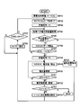
- step SP1 a timer reset is performed at step SP1.
- the load side information data S6 is read in step SP2, and the power to be supplied to the load is predicted based on the load side information data read in step SP3.
- step SP4 a command is sent to the master controller to discharge the predicted electric energy.
- step SP5 the timer value is checked.
- Steps SP2 to SP5 are repeated at regular intervals, and when the timer value reaches 30 days, a command to start capacity learning is sent to the master controller (step S6). Thereafter, the process returns to step SP1 again to reset the timer and repeat the above operation. Thus, once a month, capacity learning can be performed for the five storage battery packs A to E connected to one power converter.
- the first embodiment obtains chargeable capacity data by measuring the amount of current until the battery is fully charged after the remaining amount of the storage battery pack to be subjected to capacity learning is zero.
- the capacity learning is sequentially performed on one storage battery pack per day for the five storage battery packs A to E connected to one power converter.
- a command for starting capacity learning is issued once a month from the system controller 7 to the master controller 15. When such a command is issued, the master controller 15 starts capacity learning control in FIG.
- the storage battery pack A that performs capacity learning is specified as the initial value of the storage battery (step SP21).
- each of the storage battery packs A to E is associated with 0 to 4, and a value corresponding to the storage battery pack to be subjected to capacity learning is set in the variable X. Therefore, the value “0” corresponding to the storage battery pack A is set as the initial value of the variable X.
- step SP22 the timer is reset to 0 in step SP22. This timer is used for reference when starting the capacity learning of the next storage battery after 24 hours. Thereafter, a discharge command is given to the storage battery pack corresponding to X (hereinafter “storage battery pack X”) in step SP23. Then, a value of SOC data indicating the remaining amount sequentially transmitted from the storage battery pack X is read (step SP24), and it is repeatedly determined whether or not the SOC has become 0 in step SP25. Thereby, the specified storage battery pack is discharged until the remaining amount becomes zero.
- step SP25 If it is determined in step SP25 that the SOC has become 0, the storage battery pack X is instructed to be charged in step SP26.
- the storage battery pack instructed in step SP26 is charged under control that makes conditions such as current and temperature constant. In order to respond to power demand, it is possible that the output current at the time of discharge changes as a whole system, but for the storage battery pack that is subject to capacity learning, the change is suppressed and the output of other storage battery packs Maintain certain conditions by adjusting settings.
- step SP27 the amount of power required from the master controller for all of the storage battery packs A to E is acquired. Then, in step SP28, it is determined whether or not the electric energy requested by the remaining four storage battery packs that have not been subjected to capacity learning can be supplied.
- step SP28 If it is determined in step SP28 that the battery cannot be supplied, a command to discharge the storage battery pack X is issued (step SP35), and after waiting for 24 hours to elapse in step SP36, the capacity learning of the same storage battery pack is performed again.
- step SP29 the SOC and current value of the storage battery pack X are read (step SP29), and the amount of electric power actually stored is obtained by integrating the current amount (step SP30). Steps SP27 to SP30 are repeated until the SOC reaches 100% (step SP31), and the current integration value when the SOC reaches 100% is used as the chargeable capacity of the storage battery pack X.
- the memory area corresponding to the storage battery pack X (Step SP32).
- step SP33 it is determined whether or not the capacity learning has been completed up to the storage battery pack E.
- the capacity learning process is terminated. If not completed until E, the next storage battery pack is set as a target for capacity learning (step SP34), the value of the timer is monitored, and 24 hours have passed since the reset (step SP36, SP37). If 24 hours have elapsed, the process returns to step SP22 and the same processing is repeated.
- the storage battery pack A first subjected to capacity learning is used by the sub-controller 14 until it is completely discharged and the SOC becomes 0 while performing normal use.
- the other non-target storage battery packs B to E are used for normal use after setting the lower limit voltage of discharge or the lower limit value (10%) of the degree of charge SOC. Then, the data is updated using the accumulated current value until the SOC of the storage battery pack that is the target of capacity learning reaches from 0% to 100% as the chargeable capacity. Therefore, while one storage battery pack is charging for capacity learning, it cannot be discharged, so that the required power is supplied by the remaining four storage battery packs. *
- the same processing is sequentially performed for the storage battery packs C to E, and when the update of the chargeable capacity data for all the storage battery packs A to E is completed, the master controller ends the capacity learning control. Then, it waits for the next capacity learning command to be issued from the system controller to the master controller.
- ⁇ Second embodiment> In the second embodiment, after the storage battery pack to be subjected to capacity learning is fully charged, it is discharged until the remaining amount becomes zero, and the amount of chargeable data is obtained by measuring the amount of current during this period. Yes, the capacity learning is sequentially performed on one storage battery pack per day for the five storage battery packs A to E connected to one power converter. A command for starting capacity learning is issued once a month from the system controller 7 to the master controller 15. When such a command is issued, the master controller 15 starts the capacity learning control of FIG.
- the storage battery pack A that performs capacity learning is specified as the initial value of the storage battery (step SP41).
- each of the storage battery packs A to E is associated with 0 to 4, and a value corresponding to the storage battery pack to be subjected to capacity learning is set in the variable X. Therefore, the value “0” corresponding to the storage battery pack A is set as the initial value of the variable X.
- step SP42 the timer is reset to 0 in step SP42. This timer is used for reference when starting the capacity learning of the next storage battery after 24 hours. Thereafter, a charge command is given to the storage battery pack X in step SP43.
- step SP44 information on the amount of power supplied from the master controller to all of the storage battery packs A to E is acquired.
- step SP45 it is determined whether or not the amount of power requested by the remaining four storage battery packs that have not undergone capacity learning can be supplied. If it is determined in step SP45 that the battery cannot be supplied, a command is issued to discharge the storage battery pack X (step SP55). In step SP56, the timer waits for 24 hours to elapse, and the capacity learning of the same storage battery pack is performed again from step SP42. Do.
- step SP45 the SOC data value indicating the remaining amount sequentially transmitted from the storage battery pack X is read (step SP46), and it is checked in step SP47 whether the SOC has reached 100%. If the SOC is not 100% in step SP47, the process returns to step SP44, and the processes in steps SP44 to SP47 are repeated until the SOC reaches 100%. Thereby, the specified storage battery pack is fully charged.
- step SP47 If it is determined in step SP47 that the SOC has reached 100%, the storage battery pack X is commanded to be discharged in step SP48.
- the storage battery pack instructed in step SP48 is discharged under control in which conditions such as current and temperature are constant.
- the output current at the time of discharge may change as a whole system, but for storage battery packs subject to capacity learning, the change is suppressed and other storage battery packs Maintain constant conditions by adjusting output settings.
- Step SP49 the SOC and current value of the storage battery pack X are read (step SP49), and the amount of electric power actually discharged is obtained by integrating the amount of current (step SP50).
- Steps SP49 to SP50 are repeated until the SOC becomes 0% (step SP51), and the current accumulation value when the SOC becomes 0% is set as the chargeable capacity of the storage battery pack X as shown in FIG.
- the data is stored in the memory area corresponding to the pack X (step SP52).
- step SP53 it is determined whether or not the capacity learning has been completed up to the storage battery pack E.
- the capacity learning process is terminated. If not completed until E, the next battery pack is set as a target for capacity learning (step SP54), the value of the timer is monitored, and 24 hours have passed since the reset (step SP56, SP57).
- the storage battery pack A first subjected to capacity learning is charged by the sub-controller 14 until it is fully charged. While one storage battery pack is charging for capacity learning, it cannot be discharged, so that the required power is supplied by the remaining four storage battery packs.
- the third embodiment is an embodiment when capacity learning is performed in units of storage batteries (cells).
- the case where the capacity learning is performed by using the storage battery pack as one unit has been described.
- the present embodiment is applied to the case where the capacity learning is performed by the storage battery (cell) unit. Is.
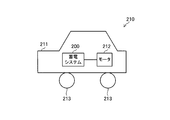
- a moving body such as an electric vehicle
- electric power is stored in a battery system 22 composed of a plurality of storage batteries (cells), and the stored electric power is supplied to a motor 24 via a power conversion unit 23 to drive wheels.
- a battery system 22 composed of a plurality of storage batteries (cells)
- the stored electric power is supplied to a motor 24 via a power conversion unit 23 to drive wheels.
- Drive is a power conversion unit 23 to drive wheels.
- FIG. 14 is a block diagram of the battery system shown in FIG.
- a dotted line represents a control signal line
- a solid line represents a power line.
- a control signal line is provided in parallel to each storage battery from the main control unit 25, and output control is performed for each storage battery according to a command from the main control unit 25.
- the control described in the first embodiment or the second embodiment can be performed in units of storage batteries (cells), and when charging / discharging normal operation, a part of the storage battery system is suitable for capacity learning. It is possible to perform capacity learning of a part of the battery of the system by charging / discharging and adjusting the shortage with other secondary batteries. Further, by dividing the storage battery into a plurality of parts and sequentially performing capacity learning during normal operation, it becomes possible to perform capacity learning of all the secondary batteries introduced into the system in a certain period.
- the capacity learning of the storage battery pack is performed sequentially every 24 hours, but the date and time when the capacity learning of each storage battery pack is started may be scheduled based on the prediction of power demand.
- the power demand is not always constant every day, and the power demand may be unpredictable. Even on the day when capacity learning is scheduled, the power demand will be larger than expected, If the excess or deficiency cannot be compensated, the capacity learning of the day is canceled and the original purpose such as peak cut is prioritized. In such a case, the capacity learning is rescheduled at another date and time, so that stable operation of the entire system can be achieved.
- another storage battery pack may be charged with a discharging current. As a result, waste of the discharge current can be suppressed as a whole.
- the fourth embodiment is an embodiment of a method for determining the start time and stop time of capacity learning.
- the power storage system shown in FIG. 15 includes a plurality of power converters 16 (PCS1, PCS2,..., PCSn), a power conversion management unit 17, a master controller 15, and a sub-controller 14.
- PCS1, PCS2,..., PCSn power converters 16
- PCSn power conversion management unit 17
- master controller 15 master controller 15
- sub-controller 14 sub-controller 14
- each of the plurality of power converters 16 a plurality of storage batteries 20 are connected in series to each power converter 16, and the system power 4 and the storage battery 20 are charged and discharged via the power converter 16, whereby the system power 4 Is supplied to the storage battery 20 and stored in the storage battery 20.
- the storage battery 20 connected in series with one power converter 16 is handled as one control unit, and the following capacity learning control process is performed.
- control of capacity learning In control of capacity learning, transmission / reception of control commands, delivery of control data, etc. are performed via communication of each device. For example, information on the storage battery 20 (information on voltage, temperature, SOC, etc.) is received by the sub-controller 14 and transmitted to the master controller 15.
- the power conversion management unit 17 performs charge / discharge control by each power converter 16 based on a charge / discharge request from the system controller.
- the start and stop of the capacity learning is determined using the storage battery data stored in the memory M of the master controller 15 by the control shown in FIGS. 17 and 18 described later, and is executed by a control command from the power conversion management unit 17.
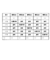
- a display monitor can be connected to the master controller 15 or the power conversion management unit 17, and the capacity learning state as shown in FIG. 16 is displayed.
- the state regarding each power converter (PCS1, PCS2,..., PCSn) which is a unit of control is displayed, the power converter performing capacity learning, the date and time when capacity learning was performed last time, and the next time
- the schedule, etc. the user is informed of the operation of the power storage system.
- the control of the flowchart shown in FIG. 17 is executed at predetermined intervals by an interrupt process, and the elapsed time from the previous capacity learning, the accumulated charge / discharge power, the variation in voltage or SOC within the series of control units. Based on (difference between maximum value and minimum value, variance, etc.), the start timing of capacity learning is determined by the following operation. In this embodiment, this control is performed by the power conversion management unit 17, but may be performed by the master controller 15.
- step SP60 When the interrupt signal is input, the process is started (step SP60).
- the timer value is read in step SP61.
- This timer is a timer that is reset when the previous capacity learning is completed, and the timer value indicates an elapsed time from the end of the previous capacity learning.
- the timer value read in step SP62 is compared with 30 days, and if it exceeds 30 days, a capacity learning start command is issued in step SP67 and the interrupt process is terminated.
- step SP62 If it is determined in step SP62 that the timer value does not exceed 30 days, the charge / discharge power integration value is read in step SP63. It is examined whether or not the value of the charge / discharge power integration amount exceeds 10,000 kWh (step SP64). If the value of the charge / discharge power integration amount exceeds 10,000 kWh, a command for starting capacity learning is issued in step SP67, and the interrupt process is terminated. If it is determined in step SP64 that the accumulated charge / discharge power value does not exceed 10,000 kWh, the voltage value of each storage battery is read in step SP65. It is checked whether or not the difference between the maximum value and the minimum value of each read voltage exceeds 1V (step SP66).
- step SP67 When the voltage exceeds 1V, that is, when it is determined that the variation of the storage battery voltage is 1V or more, a command for starting capacity learning is issued at step SP67, and the interruption process is terminated. If it is determined in step SP66 that the voltage does not exceed 1V, the interrupt process is terminated without issuing a command.
- the processing of step SP60 to step SP67 is repeatedly executed every time an interrupt signal is input.
- capacity learning is performed in a certain period even when the usage frequency of the power storage system is low. Capacity can be calculated regularly and stably.
- the current and voltage values for calculating the accumulated charge / discharge power can be measured values in the storage battery, measured values in series with the power converter, etc., but the charge / discharge energy in the control unit is measured. Any location (value) can be used.
- step SP65 and step SP66 of the above processing the variation in the voltage of the storage battery is examined, but the variation in the SOC (remaining amount) of each storage battery may be examined.
- the SOC value is read in step SP65, and if the difference between the maximum and minimum SOC is 10% or more in step SP66, a command for instructing the start of capacity learning is issued in step SP67 and the interrupt process is terminated. .
- Balancing adjustment is to improve the accuracy of balancing by temporarily disconnecting the power converter, monitoring until the storage battery voltage (open circuit voltage) is stabilized, and then determining the balancing target voltage after stabilization. Can do.
- the determination is made based on the establishment of any one of the three conditions, but a single item or a combination of two items may be used.
- the parameters for discriminating the accumulated power amount, battery voltage, and SOC variation are reset at the end of capacity learning, and the accumulated power amount is referred to the degree of change in accumulated power amount and voltage variation from the previous capacity learning.
- a command for starting capacity learning is issued when the voltage variation exceeds a preset threshold value.
- the parameter for discriminating the variation in the accumulated power amount, the storage battery voltage, and the SOC may be reset every day, by referring to the degree of change per day in the accumulated energy amount and voltage variation per day, Quick response to change is possible.
- capacity learning in FIG. 5 or FIG. 6 is started.
- the capacity learning ends the timer value is reset.
- the capacity learning stop process is a system error during capacity learning, excessive load (when there is a large amount of load that cannot be handled only by other storage batteries that do not perform capacity learning), and the temperature condition is higher than the specified temperature. When it becomes higher or lower, the capacity learning is stopped.
- the interruption of the capacity learning is determined based on the occurrence of a system error, load information, and temperature information by control according to the flowchart shown in FIG.
- step SP70 When processing is started by an interrupt signal (step SP70), first, error information is read in step SP71, and it is determined whether or not a system error has occurred in step SP72. If it is determined that a system error has occurred, a capacity learning stop command is issued in step SP77, and the interrupt process is terminated.
- step SP72 If it is determined in step SP72 that no system error has occurred, the load amount information is read in step SP73, and if it is determined in step SP74 that the load amount is greater than a predetermined value, that is, the load is excessive. In step SP77, a capacity learning stop command is issued and the interrupt process is terminated.
- step SP74 If it is determined in step SP74 that the load is smaller than the predetermined value, the temperature information T is read in step SP75, and it is determined whether or not the read temperature information T is 0 ° C. or higher and 50 ° C. or lower ( Step SP76). If it is determined that the temperature information T is not higher than 0 ° C. and lower than 50 ° C., a capacity learning stop command is issued in step SP77, and the interrupt process is terminated. If it is determined in step SP76 that the temperature information T is 0 ° C. or lower or 50 ° C. or higher, the interrupt processing is terminated without issuing a capacity learning stop command.
- capacity learning can be stopped because priority is given to returning to normal operation.
- some batteries will be disconnected from normal operation, but capacity learning is stopped when the remaining batteries cannot handle charge / discharge requests due to heavy load.
- the stored battery can be returned to normal operation.
- the temperature conditions are significantly different from normal, the battery characteristics are different. Therefore, the calculated SOH is unlikely to be effective, the temperature conditions are different from those during normal operation, and the capacity is exceeded when a predetermined threshold is exceeded. Learning will be stopped.
- the time when capacity learning is started may be performed based on the number of charge / discharge cycles. For example, the capacity learning may be started once when charging / discharging is performed 100 times.
- the present invention calculates the degree of deterioration according to the change in the capacity of each battery while performing charge / discharge control of the system, and can be used for determining the battery life and estimating the remaining capacity. It is possible to improve the estimation accuracy of the supplyable amount and improve the stability of charge / discharge control.
- the capacity learning is performed until the SOC value becomes 0% (fully discharged) to 100% (fully charged), or the SOC value becomes 100% (fully charged) to 0%.
- the chargeable capacity value is obtained by integrating the current value until it reaches (completely discharged state)
- the SOC is not necessarily 0 in this completely discharged state or fully charged state.
- the value may not be% or 100%. That is, the effect of the present invention can be obtained by measuring the chargeable capacity between values that are relatively close to 0% and 100% compared to the range in which the normal storage battery is normally used. For example, the SOC value is 3%. Or 97%.
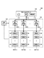
- FIG. 19 is a schematic configuration diagram of a power storage system 100 according to the second embodiment.
- the power storage system 100 includes a power storage block 101, a control block 102, and a power conversion block 103.
- a power input / output block 104 is connected to the power storage system 100.
- the system 100 may include all or part of the block 104.
- the power storage block 101 includes n storage battery packs BAT, and the power conversion block 103 includes n power converters 16.
- n is an integer of 2 or more.
- the n storage battery packs BAT are connected in parallel to each other via the n power converters 16.
- Each power converter 16 in the power conversion block 103 may be the same as the power converter 16 described in the first embodiment.
- Each storage battery pack BAT may be the same as the storage battery pack 12 in the first embodiment.
- Each storage battery pack BAT includes a plurality of storage batteries 20 connected in series. However, each storage battery pack BAT may include only one storage battery 20, or each storage battery pack BAT may include a parallel connection circuit of a plurality of storage batteries 20.
- the storage battery 20 is a lithium ion battery, a nickel hydride battery, or the like.
- charging and discharging refer to charging and discharging of the storage battery 20 in the storage block 101 unless otherwise specified.
- the n storage battery packs BAT are particularly referred to by the symbols BAT [1] to BAT [n], and the power converter 16 in the power conversion block 103 connected to the storage battery pack BAT [i] is referred to by the symbol 16 [i]. (I is an integer).
- the switch board 13 described in the first embodiment may be interposed between the storage battery pack BAT [i] and the power converter 16 [i] (see FIG. 2).
- the power input / output block 104 is a block that receives supply of discharge power from the power storage block 101 or supplies charge power to the power storage block 101 via the power conversion block 103.
- the power input / output block 104 includes the power source 111, the load 112, and the power generation device 113. Including.
- the power source 111 is a commercial AC power source corresponding to the system power 4 of the first embodiment.
- the load 112 may be the same as the load 5 of the first embodiment.
- the power generation device 113 performs power generation based on an arbitrary energy source (for example, natural energy such as sunlight or fossil fuel) and outputs generated power. However, the power generation device 113 may not be included in the block 104.
- the power conversion block 103 performs power conversion for converting the discharge power from the power storage block 101 into output power to the block 104 and power conversion for converting the power from the block 104 into charge power for the power storage block 101. Including power conversion processing.
- the power conversion block 103 may be interposed between the power source 111 or the power generation device 113 and the load 112, and power conversion for converting the power from the power source 111 or the power generation device 113 into the power supplied to the load 112 May be included in the power conversion process of the block 103.
- the power conversion process in block 103 is controlled by the control block 102.
- FIG. 20 is a block diagram showing the internal configuration of the control block 102.
- the control block 102 includes the power management device 6, the system controller 7, the master controller 15, the power converter management unit 17, and the sub-controller 14 described in the first embodiment (see FIGS. 1 and 2). It can be provided.
- the control block 102 is provided with sub-controllers 14 [1] to 14 [n] as n sub-controllers 14.
- the sub-controllers 14 [1] to 14 [n] are sub-controllers corresponding to the storage battery packs BAT [1] to BAT [n], respectively.
- the sub-controller 14 is provided in the storage battery pack BAT, here, for convenience of explanation, it is considered that the sub-controller 14 is provided outside the storage battery pack BAT (actually, the storage battery pack).
- the BAT and the sub-controller 14 can be housed in an integrated case to form a storage battery unit).
- Each sub-controller 14 acquires storage battery pack state data including the state data of the corresponding storage battery pack BAT, and transmits it to the master controller 15.
- the power storage system 100 includes, for each storage battery pack BAT, a voltage sensor that measures a terminal voltage value of the storage battery pack BAT (hereinafter referred to as pack voltage value), a current value of charge or discharge flowing through the storage battery pack BAT (hereinafter referred to as pack current value). And a temperature sensor for measuring the temperature of the storage battery pack BAT (hereinafter referred to as pack temperature), and the measured values are acquired by the sub-controller 14.
- pack voltage value corresponds to the total value of the terminal voltages of the storage batteries 20 connected in series constituting the storage battery pack BAT.
- Each sub-controller 14 calculates an SOC (state of charge) that is the degree of charge of the corresponding storage battery pack BAT based on the pack voltage value and the pack current value of the corresponding storage battery pack BAT.
- the storage battery pack state data includes a pack voltage value, a pack current value, a pack temperature, and an SOC of the storage battery pack BAT.
- the SOC of the storage battery pack BAT represents the ratio of the remaining capacity of the storage battery pack BAT to the full charge capacity of the storage battery pack BAT.
- FIG. 21 is an internal functional block diagram of the control block 102.
- the control block 102 includes a charge / discharge control unit 121 and a full charge capacity measurement unit 122.
- the charge / discharge control unit 121 includes any of a plurality of parts (mainly, for example, the master controller 15 and the power converter management unit 17) shown in FIG. 20, and the full charge capacity measurement unit 122 is also shown in FIG. An arbitrary plurality of parts (mainly, for example, the sub-controllers 14 [1] to 14 [n] or the sub-controllers 14 [1] to 14 [n] and the master controller 15).
- the charge / discharge control unit 121 performs charge / discharge control of each storage battery pack BAT through control of power conversion processing in the power conversion block 103 based on various indexes including storage battery pack state data.
- the full charge capacity measurement unit 122 is a part responsible for the capacity learning described above, and measures the full charge capacity of each storage battery pack BAT in cooperation with the charge / discharge control unit 121 and the power conversion block 103.
- the process for measuring the full charge capacity of one storage battery pack BAT is called unit capacity learning (thus, execution of unit capacity learning for the storage battery pack BAT [i] and measurement of the full charge capacity of the storage battery pack BAT [i]. Is synonymous).
- the storage battery pack BAT that is, the storage battery pack to be measured
- the measurement unit 122 can use the first or second unit capacity learning as the unit capacity learning.
- the first unit capacity learning is the same as that described in the first embodiment. That is, in the first unit capacity learning, the storage unit pack state data of the measurement target pack is monitored, and the measurement unit 122 uses the power conversion block 103 to completely discharge the measurement target pack (that is, the measurement target pack). After the battery is fully discharged, the measurement object pack is charged until the measurement object pack is fully charged. At this time, the measurement unit 122 obtains the full charge capacity of the measurement target pack based on the integrated amount of the pack current value of the measurement target pack until the measurement target pack is changed from the complete discharge state to the full charge state.
- the second unit capacity learning is the same as that described in the second embodiment. That is, in the second unit capacity learning, after the storage unit pack state data of the measurement target pack is monitored, the measurement unit 122 uses the power conversion block 103 and sets the measurement target pack to a fully charged state by charging the measurement target pack. The measurement target pack is discharged until the measurement target pack is completely discharged. At this time, the measurement unit 122 obtains the full charge capacity of the measurement target pack based on the integrated amount of the pack current value of the measurement target pack until the measurement target pack changes from the full charge state to the complete discharge state.
- the measurement unit 122 may charge the measurement target pack so that the charging current and temperature (pack temperature) of the measurement target pack are kept constant. In order to realize this, the measurement unit 122 may adjust the charge or discharge power of the storage battery pack BAT other than the measurement target pack as necessary. Similarly, in the second unit capacity learning, the measurement unit 122 may discharge the measurement target pack so that the discharge current and temperature (pack temperature) of the measurement target pack are kept constant. In order to realize this, the measurement unit 122 may adjust the charge or discharge power of the storage battery pack BAT other than the measurement target pack as necessary.
- the discharge power of the measurement target pack may be supplied to the load 112 under the control of the charge / discharge control unit 121, or to the storage battery pack BAT other than the measurement target pack. It may be supplied (that is, the storage battery pack BAT other than the measurement target pack may be charged with the discharge power of the measurement target pack).
- the charging power of the measurement target pack is supplied from the power source 111, the power generation device 113, or the storage battery pack BAT other than the measurement target pack under the control of the charge / discharge control unit 121.
- the state where the SOC of the storage battery pack BAT is 0% corresponds to the fully discharged state of the storage battery pack BAT, and the state where the SOC of the storage battery pack BAT is 100% corresponds to the fully charged state of the storage battery pack BAT.
- the state in which the SOC of the storage battery pack BAT is 3% corresponds to the complete discharge state of the storage battery pack BAT, and the state in which the SOC of the storage battery pack BAT is 97% You may make it perform 1st and 2nd unit capacity
- Balancing adjustment that equalizes the terminal voltage of each storage battery 20 forming the measurement target pack may be included in the first and second unit capacity learning.
- the content of the balancing adjustment may be the same as that of the first embodiment, and a known method (for example, an equalization method described in International Publication WO / 2011/105083) can be used for balancing adjustment.
- the value obtained by the first unit capacity learning is the chargeable capacity of the measurement target pack (the maximum electric capacity that can be stored in the measurement target pack), and the value obtained by the second unit capacity learning is capable of discharging the measurement target pack.
- Capacity maximum electric capacity that can be discharged by a measurement target pack with 100% SOC. Strictly speaking, the chargeable capacity and the dischargeable capacity may be slightly different, but both the chargeable capacity and the dischargeable capacity are a kind of full charge capacity.
- the unit capacity learning in the following explanation may be either the first or second unit capacity learning.
- a memory (not shown) provided in the control block 102 may hold the latest full charge capacity for each storage battery pack BAT.
- the measurement unit 122 uses the storage battery pack BAT as the measurement target pack to store the storage battery pack so that the original discharge function and the storage function of the storage block 101 are not disabled during capacity learning.
- the full charge capacity of each battery pack BAT is measured while switching among BAT [1] to BAT [n].
- the charge / discharge control unit 121 can normally operate one or more storage battery packs BAT other than the measurement target pack among the storage battery packs BAT [1] to BAT [n], and particularly the storage battery pack BAT that performs normal operation. This is called a normal operation pack.
- the charge / discharge control unit 121 can also set one or more storage battery packs BAT as standby packs.
- the standby pack is a storage battery pack BAT other than the measurement target pack and the normal operation pack, and the charge / discharge control unit 121 does not charge or discharge the standby pack.
- the number of waiting packs may be zero.
- the number of measurement target packs may be two or more.
- the charge / discharge control unit 121 determines the amount of discharge power (discharge power command) to be supplied from the power storage block 101 to the load 112 based on the power consumption of the load 112 connected to the power storage system 100. Amount) P D * is determined, and the power conversion block 103 is controlled so that the determined discharge power amount P D * is supplied from the power storage block 101 to the load 112.
- the measurement target pack BAT [4] is not used for the discharge control. That is, in the discharge control, the charge / discharge control unit 121 controls the power conversion block 103 so that the discharge power amount P D * is supplied to the load 112 from the normal operation packs BAT [1] to BAT [3].
- the discharge control is also executed during a period in which unit capacity learning is performed for any of the storage battery packs BAT. That is, during the period in which the measurement unit 122 measures the full charge capacity of any storage battery pack BAT (that is, the unit capacity learning execution period for the measurement target pack BAT [4]), the charge / discharge control unit 121
- the normal operation packs BAT [1] to BAT [3] can be discharged by discharge control. Thereby, capacity learning can be performed without impairing the power supply function to the load 112.
- the charge / discharge control unit 121 changes the discharge power amount P D * to the normal operation packs BAT [1] to BAT [3] based on the storage battery pack state data for the normal operation packs BAT [1] to BAT [3]. If it is determined that the amount of electric power is larger than the amount of electric power that can be discharged, the measurement of the full charge capacity by the measurement unit 122 is stopped, and the discharge electric energy P is applied to the load 112 using the packs BAT [1] to BAT [4]. In order to supply D * , the storage battery pack BAT [4] that was the measurement target pack is incorporated into the normal operation pack, and the storage battery pack BAT [4] is discharged together with the storage battery packs BAT [1] to BAT [3]. Make it.
- the pack BAT [4] to be discharged by being incorporated in the normal operation pack for discharging is also the measurement target pack that has been charged in unit capacity learning immediately before being incorporated in the normal operation pack. Alternatively, it may be a measurement target pack that has been discharged in unit capacity learning.
- the power consumption amount used for determining the discharge power amount P D * may be an actual measurement value of the power consumption amount of the load 112 or a predicted value of the power consumption amount of the load 112.
- a prediction unit (not shown) in the control unit 102 uses a known method based on the history data of the power consumption amount of the load 112, the day of the week for the prediction, the weather data for the time of the prediction, and the like.
- the power consumption amount of the load 112 in the time zone can be predicted.
- the charge / discharge control unit 121 may determine the discharge power amount P D * in the time period using the predicted value.
- the discharge power amount P D * can be covered by the packs BAT [1] to BAT [3]. if the discharge power amount P D * is reduced to the extent, the measurement unit 122 may re-execute the unit capacity learning for battery packs BAT [4].
- the measuring unit 122 may BAT [1] after discharge power amount to the extent that the discharge amount of power P D * is can cover P D * is reduced at ⁇ BAT [3], since further waits for a predetermined time elapses, the unit for the storage battery pack BAT [4] Re-execute capacity learning.
- the charge / discharge control unit 121 determines the amount of charge power (charge power command) from the charge source to the power storage block 101 based on the amount of power supplied from the charge source (111 or 113) connected to the power storage system 100. Amount) P C * is determined, and the power conversion block 103 is controlled such that the determined charging power amount P C * is supplied from the charging source to the power storage block 101.
- the measurement target pack BAT [4] is not used for the charge control. That is, in the charge control, the charge / discharge control unit 121 controls the power conversion block 103 so that the charge power amount P C * is supplied from the charge source to the normal operation packs BAT [1] to BAT [3].
- the charging control is also executed during a period in which unit capacity learning is performed for any of the storage battery packs BAT. That is, during the period in which the measurement unit 122 measures the full charge capacity of any storage battery pack BAT (that is, the unit capacity learning execution period for the measurement target pack BAT [4]), the charge / discharge control unit 121 The normal operation packs BAT [1] to BAT [3] can be charged by the charge control. Thereby, capacity learning can be performed without impairing the power storage function of the power storage system 100.
- the charge / discharge control unit 121 changes the charge power amount P C * to the normal operation packs BAT [1] to BAT [3] based on the storage battery pack state data for the normal operation packs BAT [1] to BAT [3]. If it is determined that the amount of charge is larger than the chargeable power amount, the measurement of the full charge capacity by the measurement unit 122 is stopped, and the charge power amount P C * is included in the entire packs BAT [1] to BAT [4]. In order to be supplied, the storage battery pack BAT [4], which was the measurement target pack, is incorporated into the normal operation pack, and the storage battery pack BAT [4] is charged together with the storage battery packs BAT [1] to BAT [3].
- the pack BAT [4] to be charged by being incorporated in the normal operation pack to be charged is also a measurement target pack that has been charged in unit capacity learning immediately before being incorporated into the normal operation pack. Alternatively, it may be a measurement target pack that has been discharged in unit capacity learning.
- At least one of the power source 111 and the power generation device 113 can be the above-described charging source (charging source for charging the normal operation pack).
- the charge / discharge control unit 121 may determine the charge power amount P C * based on the usage fee of the power from the power source 111 or the like.
- the charge / discharge control unit 121 may determine the charge power amount P C * based on the power generation amount of the power generation device 113.
- the measurement unit 122 may re-execute the unit capacity learning for battery packs BAT [4]. However, at this time, in preparation for the amount of power supplied from the charging source (such as the amount of power generated by the power generation device 113) to rise again unexpectedly, or the pack voltage value of the pack BAT [4] is stabilized.
- the unit capacity learning for the storage battery pack BAT [4] may be performed again.
- the pack temperature of the pack BAT [i] is within a predetermined temperature range ( For example, when it is confirmed that the temperature deviates from 0 ° C. to 50 ° C.), the measurement unit 122 determines the full charge capacity of the storage battery pack BAT [i] because it is difficult to ensure measurement accuracy. Measurement may be stopped.
- FIG. 22 is an internal functional block diagram of the control block 102 according to the fifth embodiment.
- a parameter detection unit 140 is provided in the control block 102 (the same applies to other examples described later).
- the parameter detection unit 140 is formed by the sub-controllers 14 [1] to 14 [n] or the sub-controllers 14 [1] to 14 [n] and the main controller 15.
- the parameter detection unit 140 detects a parameter indicating the state of each storage battery pack BAT. Then, the measurement unit 122 according to the fifth embodiment performs the unit capacity learning between the storage battery packs BAT [1] to BAT [n] in accordance with the parameters detected by the parameter detection unit 140 (hereinafter, measurement order). Decide).
- the detected parameter is a parameter that is estimated to be related to the deterioration state of each storage battery pack BAT. Basically, the measurement unit 122 determines that the storage battery pack BAT that is estimated to have a higher deterioration degree has a higher deterioration degree. A measurement order is determined so that it becomes a measurement object pack before the storage battery pack BAT estimated to be small.
- the parameter detection unit 140 includes parts referred to by reference numerals 141 to 143 and 145.
- the measurement unit 122 can perform unit capacity learning intermittently for each storage battery pack BAT.
- FIG. 23 at time t j [1], t j [2]..., T j [n], storage battery packs BAT [1], BAT [ 2],..., Suppose that the j-th unit capacity learning for BAT [n] has been completed.
- the time t j [i + 1] is later than the time t j [i], and for any storage battery pack BAT between the times t j [1] to t j [n]. It is assumed that the (j + 1) th unit capacity learning is not performed.
- the time measuring unit 141 includes n timers corresponding to n storage battery packs BAT, and each timer is used to measure the elapsed time T from the end time of the j-th unit capacity learning for each storage battery pack BAT. Measure EL .
- the power integration amount calculation unit (power amount detection unit) 142 charges the storage battery pack BAT during the integration target period based on the corresponding pack current value (and also uses the pack voltage value as necessary) for each storage battery pack BAT.
- a power integrated amount PSUM that is an integrated value of the power amount and the discharge power amount is obtained.
- the start time of the integration target period for the storage battery pack BAT [i] is jth unit capacity learning. Is the end time t j [i], and the end time is the current time.
- the variation detection unit 143 obtains a variation amount VR representing the degree of variation in voltage or SOC between the plurality of storage batteries 20 for each storage battery pack BAT.
- a cell voltage detector (not shown) that measures a terminal voltage value (hereinafter referred to as a cell voltage value) of the storage battery 20 for each storage battery 20 can be provided in the power storage system 100.
- the variation detection unit 143 can acquire each cell voltage value of the plurality of storage batteries 20 for each storage battery pack BAT.
- the variation detection part 143 can obtain
- the difference between the maximum value and the minimum value of the plurality of cell voltage values for the plurality of storage batteries 20 or the variance of the plurality of cell voltage values can be obtained as the variation amount VR.
- the variation detection part 143 calculates
- the variation amount VR corresponding to the degree of variation in the SOC of the storage battery 20 may be obtained.
- the difference between the maximum and minimum values of the plurality of SOCs for the plurality of storage batteries 20 or the dispersion of the plurality of SOCs may be obtained as the variation amount VR.
- Parameter detection unit 140 for each battery pack BAT, the elapsed time T EL, monitor the power accumulated amount P SUM and variation amount VR, executes the series of processing of steps SP161 ⁇ SP167 in FIG.
- the series of processes is periodically executed for each storage battery pack BAT using an interrupt process or the like.
- the operation flowchart composed of steps SP161 to SP167 may be considered to be equivalent to that of FIG.
- the parameter detection unit 140 can perform the following processing for the storage battery pack BAT [i].
- Parameter detection unit 140 acquires the elapsed time T EL of the battery pack BAT [i] from the timer (step SP161), when the elapsed time T EL is the predetermined time period (e.g. 30 days of time) (step SP162 Y), a measurement start command CM [i] is issued (step SP167).
- the measurement start command CM [i] is a command for requesting execution (start of execution) of unit capacity learning for the storage battery pack BAT [i], and the command issuance unit 145 issues the command.
- the parameter detection unit 140 acquires the integrated power amount PSUM for the storage battery pack BAT [i] (step SP163), and the integrated power amount PSUM is equal to the predetermined power amount (step SP163). For example, when it is equal to or greater than 10,000 kWh (kilowatt ⁇ hour) (Y in step SP164), a measurement start command CM [i] is issued (step SP167).
- step SP165 If the power accumulated amount P SUM is less than the predetermined amount of power, when the parameter detecting unit 140 obtains the variation amount VR of the battery pack BAT [i] (step SP165), the variation amount VR is equal to or larger than the predetermined amount ( In step SP166 Y), a measurement start command CM [i] is issued (step SP167).
- the parameter detection unit 140 can individually control whether the command is issued for each storage battery pack BAT.
- the measurement unit 122 can start executing the (j + 1) th unit capacity learning for the storage battery pack BAT [i].
- the elapsed time T EL , the integrated power amount PSUM, and the variation amount VR are first, second, and third parameters for determining the measurement order.
- the measurement order may be determined using only one arbitrary parameter or two arbitrary parameters.
- the storage battery pack BAT corresponding to a relatively large elapsed time T EL , power integrated amount P SUM or variation amount VR has a relatively small elapsed time T EL , power integrated amount P SUM or
- the measurement unit 122 determines the measurement order so that the measurement target pack is prior to the storage battery pack BAT corresponding to the variation amount VR (it may be considered that the main body of this determination is the command issuing unit 145). , It may be considered that the issuing unit 145 is provided in the measuring unit 122). As a result, the measurement unit 122 measures the full charge capacity of each storage battery pack BAT while switching the measurement target pack among the plurality of storage battery packs BAT according to the detection parameter by the parameter detection unit 140.
- the above-described measurement order determination process with reference to the elapsed time TEL periodically and stably detects a change in the full charge capacity corresponding to the storage deterioration of the storage battery pack, even in situations where the storage battery pack is not charged or discharged frequently. can do.
- the above-described measurement order determination process with reference to the integrated power amount PSUM a change in the full charge capacity of the storage battery pack that is estimated to be relatively high in use frequency and high in the degree of deterioration can be confirmed relatively quickly. Further, it is estimated that a state where the variation amount VR is large corresponds to a state where the degree of deterioration is relatively large.
- the above-described measurement order determination process with reference to the variation amount VR a change in the full charge capacity of the storage battery pack that is estimated to have a high degree of deterioration can be preferentially confirmed over other storage battery packs.
- the time measuring unit 141 is used for each storage battery pack BAT from the start of use of the storage battery pack BAT (when the storage battery pack BAT is installed in the power storage system 100 or when the storage battery pack BAT is charged or discharged for the first time).
- the elapsed time may be measured as the elapsed time T EL a.
- the time measuring unit 141 a preset plurality of different reference time to each other, the storage battery pack BAT [i] starts the elapsed measuring After time T EL reaches the one of the reference time command CM [i] is issued The If the difference between two adjacent reference times among a plurality of reference times is set to the predetermined time (for example, 30 days), the same result as the method shown in FIG. 24 is obtained.
- the arithmetic unit 142 for each battery pack BAT, may be an integrated quantity of electric power from the use start time of the battery pack BAT to seek the power accumulated amount P SUM. That is, for each storage battery pack BAT, the calculation unit 142 may determine the integrated power amount PSUM after fixing the start time of the integration target period to the use start time of the storage battery pack BAT. In this case, the calculating unit 142, a preset plurality of different reference power from each other, battery packs BAT [i] Measurement starting command CM With power integrated amount P SUM is one of the reference power to reach the [i] is publish. If the difference between two reference power amounts adjacent to each other among the plurality of reference power amounts is set to the predetermined power amount (for example, 10000 kWh), the same result as the method shown in FIG. 24 is obtained.
- the predetermined power amount for example, 10000 kWh
- the sub-controller 14 [i] may be provided with a function for performing unit capacity learning for the storage battery pack BAT [i]. . Accordingly, each sub-controller 14 can manage unit capacity learning (including management of execution timing) for the corresponding storage battery pack BAT without depending on the host controller.
- a measurement order determination form based on such management is referred to as a first measurement order determination form.
- the host controller refers to a controller on the upper side of the sub-controller 14.
- the host controller includes the main controller 15 and may further include the system controller 7 and the power management apparatus 6.
- the measurement order may be determined by the following second and third measurement order determination forms different from the first measurement order determination form.
- the host controller realizes all the functions of the parameter detection unit 140 and the measurement unit 122 without depending on the sub-controller 14.
- the upper controller obtains the first to third parameters and the storage battery pack state data for each storage battery pack BAT without relying on the sub-controller 14, and also schedules the capacity learning including the measurement start command issue timing control. Take control. Therefore, in the second measurement order determination mode, the sub-controllers 14 [1] to 14 [n] can be omitted from the control unit 102. It may be considered that the first to third parameters are included in the storage battery pack state data.
- the technique described in the fifth embodiment can be realized.
- a plurality of storage battery packs BAT can simultaneously become measurement target packs (the same applies to other examples described later).
- the charge-discharge control unit 121 the time of forming the discharge control based on the discharge amount of power above P D (command value of the discharge power) *, described above in when forming a charge control charging power amount (charge power based on the command amount) P C *, sets the maximum permitted number of measured pack sets a number of normal operation pack.
- the measurement unit 122 limits the execution of unit capacity learning as necessary so that the number of storage battery packs BAT for which unit capacity learning is simultaneously performed does not exceed the maximum permitted number of measurement target packs.
- the measurement unit 122 performs unit capacity learning of the packs BAT [1] and BAT [2], but the measurement start command CM [3] is received during the unit capacity learning for the packs BAT [1] and BAT [2].
- the measurement unit 122 executes the unit capacity learning of the pack BAT [3] according to the measurement start command CM [3], and the unit capacity learning for the pack BAT [1] or BAT [2] is completed. Hold until
- the measurement unit 122 compares the variation amounts VR of the packs BAT [1] and BAT [2]. To do.
- the measurement unit 122 starts executing unit capacity learning for the pack BAT [1], while the pack BAT [1]
- the execution of unit capacity learning for [2] may be suspended until the unit capacity learning for pack BAT [1] is completed.
- control block 102 is formed so that the total measurement command is periodically issued in the control block 102, and when the total measurement command is issued, the measurement unit 122 performs the first measurement at the time of issuing the total measurement command.
- the measurement order may be determined based on the first, second, or third parameter, and unit capacity learning for each storage battery pack BAT may be performed according to the determined measurement order.
- the storage battery pack BAT corresponding to the relatively large elapsed time T EL , power integrated amount P SUM, or variation amount VR has a relatively small elapsed time T EL , power integrated amount P SUM or
- the measurement unit 122 may determine the measurement order so that the pack to be measured comes before the storage battery pack BAT corresponding to the variation amount VR.
- the charge / discharge control unit 121 performs the discharge control based on the above-described discharge power amount P D * when performing the discharge control, and performs the above-described charge power amount P C when performing the charge control.
- Each of the packs BAT [6] to BAT [10] can be a measurement target pack or a standby pack.
- Pack BAT [6] ⁇ BAT [10 ] may be all waiting pack, but in situations ST A, pack BAT [6] is a measurement target pack and pack BAT [7] ⁇ BAT [10 ] is Suppose that it is a waiting pack.
- the charging and discharging control unit 121 can perform discharge control, in this case, the latest power amount (measured value or predicted value) based on the discharge amount of power P D * sequential loading 112 It can be updated.
- the charge / discharge control unit 121 All or part of the standby packs BAT [7] to BAT [10] can be incorporated into the normal operation pack.
- the charge / discharge control unit 121 packs the storage battery pack (any one or all of BAT [7] to BAT [10]) incorporated in the normal operation pack into the pack BAT [1] to BAT [5.
- the charging and discharging control unit 121 can perform charging control, in this case, it is possible to slide into successively update the latest supply electric energy to the basis charged electrical energy P C * of the charge source . And if the latest charge power amount P C * obtained by the updating is determined to be greater than the chargeable amount of electric power in normal operation pack BAT [1] ⁇ BAT [5 ], the charge-discharge control unit 121, All or part of the standby packs BAT [7] to BAT [10] can be incorporated into the normal operation pack.
- the charge / discharge control unit 121 uses a battery pack (any one or all of BAT [7] to BAT [10]) newly incorporated in the normal operation pack based on the power supplied from the charging source. Charge with BAT [5].
- the charge / discharge control unit 121 uses any of the detection parameters of the parameter detection unit 140 to incorporate any standby pack into the normal operation pack. Can be determined.
- the charge / discharge control unit 121 includes a relatively small elapsed time T EL and a power integration amount that are relatively smaller than the storage battery pack BAT corresponding to a relatively large elapsed time T EL , power integration amount P SUM, or variation amount VR.
- the storage battery pack BAT corresponding to the PSUM or the variation amount VR may be preferentially incorporated in the normal operation pack.
- the standby pack can also be considered as a candidate for a measurement target pack that can become a measurement target pack in the near future.
- a unit learning process is performed as soon as possible for a standby pack corresponding to a relatively large elapsed time T EL , electric power integration amount P SUM, or variation amount VR, that is, a standby pack estimated to have a relatively high degree of deterioration. Is preferable. Due to the above-described incorporation process, standby packs that are estimated to have a relatively high degree of deterioration are maintained as standby packs as much as possible to prepare for the start of capacity learning.
- the measurement unit 122 may perform unit capacity learning for each storage battery pack BAT in a predetermined order. That is, for example, the control block 102 is formed so that the total measurement command is periodically issued in the control block 102, and when the total measurement command is issued, the measurement unit 122 sets n pieces in accordance with a predetermined order. A predetermined sequence measurement process for measuring the full charge capacity of each storage battery pack BAT may be performed while sequentially switching the measurement target packs among the storage battery packs BAT.
- control block 102 may include the prediction unit (not shown) that predicts the power consumption amount of the load 112. Then, the measurement unit 122 refers to a predicted value (hereinafter, predicted power amount) of the power consumption of the load 112 in a prediction target period having a predetermined time length (for example, a time length for one day), and performs prediction. An average amount of the predicted power amount in the target period may be obtained, a period in which the predicted power amount is lower than the average amount is detected in the prediction target period, and the predetermined order measurement process may be performed in the detection period.
- predicted power amount a predicted value of the power consumption of the load 112 in a prediction target period having a predetermined time length (for example, a time length for one day)
- the control block 102 can cause the measurement unit 122 to intermittently perform a predetermined order measurement process by intermittently issuing a total measurement command.
- a timer can be provided in the control block 102 for measuring the elapsed time T EL ′ from the time when the j-th predetermined order measurement process is completed. Then, the control block 102 resets the timer value and issues a new total measurement command when the elapsed time T EL ′ reaches a predetermined time (for example, 30 days), and sends a new total measurement command to the measurement unit 122.
- the (j + 1) th predetermined order measurement process may be executed.
- the integrated power amount calculation unit 142 in FIG. 22 is based on the end time of the j-th predetermined order measurement process, and the integrated values of the charged power amount and the discharged power amount of the n storage battery packs BAT (hereinafter, the integrated power amount).
- P TOTAL the integrated power amount
- the integrated power amount P TOTAL is a total value of integrated values for n storage battery packs BAT.
- the measurement part 122 may perform the predetermined order measurement process of the (j + 1) th time, when the electric power integration amount PTOTAL reaches predetermined electric energy.
- the post-process for charging the measurement target pack is performed (the first unit capacity learning is therefore the pre-discharge process). And post-charging step).
- a post-process for discharging the measurement target pack is performed after the pre-process for bringing the measurement target pack into a fully charged state by charging the measurement target pack (therefore, the second unit capacity learning is charged). Including the pre-process and post-discharge process).
- balancing adjustment can be performed between the pre-process and the post-process.
- a technique that contributes to shortening the execution time of unit capacity learning for a plurality of storage battery packs will be described.
- n 10
- the maximum permitted number of measurement target packs is 1, but it may be 2 or more.
- measurement unit 122 acquires the SOCs of storage battery packs BAT [2] to BAT [10], and the storage battery pack corresponding to the lowest SOC among the SOCs of storage battery packs BAT [2] to BAT [10].
- the pack BAT [2] is set as the next measurement target pack.
- the measurement unit 122 discharges the pack BAT [2] during the period JJ so that the SOC of the pack BAT [2] becomes zero or approaches zero (that is, the pre-process in the first unit capacity learning is performed). Keep running).
- the measurement unit 122 performs the first unit capacity learning for the pack BAT [2].
- the measurement unit 122 may further perform balancing adjustment on the pack [2] during the period JJ.
- the measurement unit 122 acquires the SOCs of the storage battery packs BAT [2] to BAT [10], and the storage battery pack corresponding to the highest SOC among the SOCs of the storage battery packs BAT [2] to BAT [10]. To the next measurement target pack. Here, it is assumed that the pack BAT [3] is set as the next measurement target pack. The measurement unit 122 charges the pack BAT [3] during the period JJ so that the SOC of the pack BAT [3] becomes 100% or approaches 100% (that is, before the second unit capacity learning). Perform the process).
- the measuring unit 122 performs the second unit capacity learning for the pack BAT [3]. At this time, all or part of the previous process for the pack BAT [3] has been completed, so the second unit capacity learning for the pack BAT [3] is completed in a relatively short time.
- the measurement unit 122 may further perform balancing adjustment on the pack [3] during the period JJ.
- the power storage system in the first or second embodiment includes a power supply device.
- the power storage system and the power supply device according to the first embodiment include arbitrary parts shown in FIGS. 1 to 3 and 15, and power is supplied between the plurality of storage battery packs 12 and an external device that inputs or outputs power.
- a power converter (for example, one or more power converters 16) that performs conversion is included.
- the power supply apparatus includes blocks 101 to 103 in FIG. 19, where the block 103 corresponds to the power conversion unit and the block 104 corresponds to the external device.
- the power storage system 200 that is the power storage system of the first embodiment or the power storage system 100 of the second embodiment may be mounted on a vehicle 210 that is an example of a moving object.
- the vehicle 210 includes a vehicle body 211 as a moving main body and a motor (power source) that converts electric power from the power storage system 200 (that is, discharge power of the plurality of storage battery packs 12 or the plurality of storage battery packs BAT) into power for moving the vehicle body 211. ) 212 and drive wheels 213 that move the vehicle body 211 by rotating with the power obtained by the motor 212.
- the moving body may be a moving body that is not classified as a vehicle (for example, a ship or a walking robot).
Landscapes
- Engineering & Computer Science (AREA)
- Power Engineering (AREA)
- Manufacturing & Machinery (AREA)
- Chemical & Material Sciences (AREA)
- Chemical Kinetics & Catalysis (AREA)
- Electrochemistry (AREA)
- General Chemical & Material Sciences (AREA)
- Microelectronics & Electronic Packaging (AREA)
- Charge And Discharge Circuits For Batteries Or The Like (AREA)
Abstract
Description
本発明の第1実施形態について、図面を参照して以下に説明する。本実施形態では電力管理システムの蓄電池としてリチウムイオン電池を用いているが、これ以外の蓄電池、例えばニッケル水素電池、ニッケルカドミウム電池等であってもよい(後述の第2実施形態でも同様)。蓄電池集合体とするのは、負荷の必要電力に対応するための電圧と電流とを得るためであるので、蓄電池集合体を構成する単位蓄電池の数、単位蓄電池を組み合わせた蓄電池パックの数等は、電力管理システムの仕様に応じ適宜なものとできる。また、以下で述べる個数、電圧、電力等は、説明のための例示であり、電力管理システムの電力仕様等に応じ適宜変更が可能である。
図1は、電力管理システム1が設けられる施設の例として、蓄電池集合体2を備える工場施設3の構成を示す図である。この工場施設3は、電力源として系統電力4を用い、工場の負荷5として、一般照明、一般空調、厨房器具、サーバやPC等の事務機器、工場内空調等の必要電力をまかなうものである。この工場の負荷5の変動等に対応するため、工場施設3は、数MWhの蓄電池集合体2を備える。
システムコントローラ7は、電力管理装置6から電力管理情報S7の送信を受け、充放電制御装置8に対し、負荷に供給すべき電力を賄うための充放電制御指令S1および後述する容量学習を開始する指令を送信する機能を有する制御装置である。
充放電制御装置8は、上記のようにシステムコントローラ7からの充放電制御指令S1を受けて、複数の蓄電池パック12からなる蓄電池集合体2を充放電制御する装置である。充放電制御装置8は、マスタコントローラ15と、電力変換器16を管理する電力変換器管理部17と、蓄電池集合体2を蓄電池パック12単位で管理するサブコントローラ14を含んで構成される。後述されるように、充放電制御装置8に8つの電力変換器16を設けることができる。
マスタコントローラ15は、システムコントローラ7から受け取った充放電制御指令S1に基づいて、それぞれの電力変換器16に対する集合体充放電制御指令S5を電力変換器管理部17に送信する機能を有する制御装置である。また、マスタコントローラ15はメモリM(保持部;図4参照)を備えており、後述する容量学習により測定した蓄電池パック12の各々の充電可能容量を記憶・保持する。
サブコントローラ14は蓄電池パック12の状態データを含む蓄電池パック状態データS3を入手しマスタコントローラ15へ送信する。なお、蓄電池パック状態データS3は、蓄電池パック12の状態を示す情報であり、蓄電池パック12の電圧、温度、電流、充電度であるSOC(State Of Charge)等を含む。
マスタコントローラ15は信号線によりハブ19を経由して各サブコントローラ14とつながっており、サブコントローラ14は、マスタコントローラ15の指示によりスイッチ基板13の制御を行うとともに、サブコントローラ14から蓄電池パック12の各種データがマスタコントローラ15に送られる。なお、スイッチ基板13は、高電圧スイッチ回路を備えており、蓄電池パック12の蓄電池20の出力を電力変換器16に出力するか否かの切換を行う。
上述の装置において、システムコントローラ7は図4の制御に従って、マスタコントローラ15に容量学習開始の指示を行ない、マスタコントローラ15は図5のフローに従って容量学習制御を行う。この容量学習制御では、図7に示すように、容量学習の成される蓄電池バックが順次蓄電池パックA,B,・・・と切り替わるように原則1日に1つずつ蓄電池パック12の容量学習を行い、各蓄電池パック12の蓄電可能容量を実測し、マスタコントローラ15はメモリMに記憶されている各蓄電池パックに対する蓄電可能容量データの更新を行う。
第1の実施例は、容量学習の対象とする蓄電池パックの残量をゼロにした後、満充電になるまでの間の電流量を測定することで充電可能容量のデータを得るものであり、これを1つの電力変換器に接続されている5つの蓄電池パックA~Eに対して1日に1つの蓄電池パックについて順次容量学習を行なう。システムコントローラ7からマスタコントローラ15に毎月1回、容量学習を開始させる指令が発せられる。かかる指令が発せられると、マスタコントローラ15は図5の容量学習制御を開始する。
第2の実施例は、容量学習の対象とする蓄電池パックを満充電にした後、残量がゼロになるまで放電し、この間の電流量を測定することで充電可能容量のデータを得るものであり、これを1つの電力変換器に接続されている5つの蓄電池パックA~Eに対して1日に1つの蓄電池パックについて順次容量学習を行なう。システムコントローラ7からマスタコントローラ15に毎月1回、容量学習を開始させる指令が発せられる。かかる指令が発せられると、マスタコントローラ15は図6の容量学習制御を開始する。
第3の実施例は、蓄電池(セル)単位で容量学習を行う場合の実施例である。上記第1の実施例および第2の実施例では、蓄電池パックを1つの単位として容量学習を行う場合について説明したが、本実施例は、容量学習を蓄電池(セル)単位で行う場合に適用したものである。
第4の実施例は、容量学習の開始時期および停止時期を決定する方法についての実施例である。
容量学習開始決定処理は図17に示すフローチャートの制御を割込み処理により所定間隔で実行し、前回の容量学習からの経過時間、充放電電力積算量、制御単位の直列内での電圧またはSOCのばらつき(最大値と最小値の差、分散など)に基づいて、容量学習の開始タイミングを以下の動作により決定する。本実施例ではこの制御は電力変換管理部17で行う場合を示すが、マスタコントローラ15で行ってもよい。
次に容量学習の停止処理について説明する。容量学習停止処理は、容量学習を行っている最中にシステムエラー、負荷過多(負荷量が多く、容量学習を行っていない他の蓄電池のみでは対応できない場合)、温度条件が所定の温度よりも高くなった場合あるいは低くなった場合に容量学習を停止させる処理を行う。容量学習停止処理は割込み処理により図18に示すフローチャートに従った制御により容量学習の停止をシステムエラーの発生、負荷情報、温度情報に基づいて決定する。
第5の実施例を説明する。図22は、第5の実施例に係る制御ブロック102の内部機能ブロック図である。制御ブロック102にパラメータ検出部140が設けられている(後述の他の実施例でも同様)。パラメータ検出部140は、サブコントローラ14[1]~14[n]にて形成される又はサブコントローラ14[1]~14[n]及びメインコントローラ15にて形成される。
蓄電池20ごとに蓄電池20の端子電圧値(以下セル電圧値という)を測定するセル電圧検出器(不図示)を蓄電システム100に設けておくことができる。そのようなセル電圧検出器を蓄電池パックBATごとに設けておくことで、ばらつき検出部143は、蓄電池パックBATごとに複数の蓄電池20の夫々のセル電圧値を取得することができる。そして、ばらつき検出部143は、蓄電池パックBATごとに、セル電圧値のばらつき度合いに応じたばらつき量VRを求めることができる。例えば、複数の蓄電池20についての複数のセル電圧値の最大値及び最小値間の差、又は、該複数のセル電圧値の分散をばらつき量VRとして求めることができる。
或いは、ばらつき検出部143は、セル電圧値及びパック電流値に基づき蓄電池20ごとに蓄電池20のSOC(蓄電池20の満充電容量(例えば既知の定格容量)に対する蓄電池20の残容量の比)を求め、蓄電池パックBATごとに、蓄電池20のSOCのばらつき度合いに応じたばらつき量VRを求めても良い。例えば、複数の蓄電池20についての複数のSOCの最大値及び最小値間の差、又は、該複数のSOCの分散をばらつき量VRとして求めても良い。
第6の実施例を説明する。第6の実施例では、第2又は第3測定順序決定形態が蓄電システム100に採用されたことを想定する。この場合、蓄電システム100の本来の機能に影響がでないように、容量学習のスケジュール調整などを行うことができる。
第7の実施例を説明する。第7の実施例では、第2又は第3測定順序決定形態が蓄電システム100に採用されたことを想定し、待機パックの関連技術を説明する。
同様に、状況STAにおいて、充放電制御部121は充電制御を行うことができ、この場合、充電源の最新の供給電力量に基づき充電電力量PC *を順次更新してゆくことができる。そして更新によって得られた最新の充電電力量PC *が通常動作パックBAT[1]~BAT[5]にて充電可能な電力量よりも大きいと判断される場合、充放電制御部121は、待機パックBAT[7]~BAT[10]の全部又は一部を通常動作パックに組み込むことができる。充放電制御部121は、通常動作パックに新たに組み込んだ蓄電池パック(BAT[7]~BAT[10]の何れか又は全部)を、充電源からの供給電力に基づき、パックBAT[1]~BAT[5]と共に充電させる。
第8の実施例を説明する。測定部122は、予め定められた順序で各蓄電池パックBATに対する単位容量学習を行っても良い。即ち例えば、制御ブロック102において定期的に総測定コマンドが発行されるように制御ブロック102を形成しておき、総測定コマンドが発行されたとき、測定部122は、予め定められた順序に従ってn個の蓄電池パックBATの中で測定対象パックを順次切り替えながら各蓄電池パックBATの満充電容量を測定する所定順序測定処理を成してもよい。
第9の実施例を説明する。第9の実施例で述べる技術は、矛盾なき限り、上述の第1実施形態にも適用可能であるし、第2実施形態において上述した他の任意の技術にも適用可能である。
上述の説明文中に示した具体的な数値は、単なる例示であって、当然の如く、それらを様々な数値に変更することができる。上述の実施形態に適用可能な注釈事項又は本発明に関わる事項として、以下に、注釈1及び注釈2を記す。各注釈に記載した内容は、矛盾なき限り、任意に組み合わせることが可能である。
第1又は第2実施形態における蓄電システムには、電源装置が内包されているといえる。第1実施形態における蓄電システム及び電源装置には、図1~図3及び図15に示す任意の部位が含まれ、複数の蓄電池パック12と電力の入力又は出力を行う外部機器との間で電力変換を行う電力変換部(例えば、1以上の電力変換器16)が含まれる。第2実施形態において、電源装置は、図19のブロック101~103から成り、ブロック103が上記電力変換部に相当すると共にブロック104が上記外部機器に相当する。
また、図26に示す如く、第1実施形態の蓄電システム又は第2実施形態の蓄電システム100である蓄電システム200を、移動体の例である車両210に搭載するようにしても良い。車両210は、移動本体部としての車体211と、蓄電システム200からの電力(即ち複数の蓄電池パック12又は複数の蓄電池パックBATの放電電力)を車体211を移動させる動力に変換するモータ(動力源)212と、モータ212によって得られた動力にて回転することで車体211を移動させる駆動輪213と、を備える。移動体は、車両に分類されない移動体(例えば船舶、歩行ロボット)であっても良い。
2 蓄電池集合体
3 工場施設
4 系統電力
5 工場の負荷
6 電力管理装置
7 システムコントローラ
8 充放電制御装置
9 負荷電力管理装置
10 総合電力監視装置
11 蓄電池電力管理装置
12 蓄電池パック
13 スイッチ基板
14 サブコントローラ
15 マスタコントローラ100 蓄電システム
101 蓄電ブロック
102 制御ブロック
103 電力変換ブロック
104 電力入出力ブロック
121 充放電制御部
122 満充電容量測定部
140 パラメータ検出部
BAT[1]~BAT[n] 蓄電池パック
Claims (14)
- 並列接続された複数の蓄電部と、
前記複数の蓄電部の中で測定対象の蓄電部を切り替えながら各蓄電部の満充電容量を測定する測定部と、
前記複数の蓄電部の充放電制御を行う充放電制御部と、を備え、
前記充放電制御部は、前記測定部が前記測定対象の蓄電部の満充電容量を測定している期間中において、前記複数の蓄電部に含まれる、前記測定対象以外の他の蓄電部に、充電又は放電を行わせる
ことを特徴とする蓄電システム。 - 各蓄電部の状態を示すパラメータを検出するパラメータ検出部を更に備え、
前記測定部は、前記パラメータ検出部により検出された前記パラメータに応じ、前記複数の蓄電部間における前記測定の順序を決定する
ことを特徴とする請求項1に記載の蓄電システム。 - 前記パラメータ検出部は、前記パラメータとして前記蓄電部ごとに前記蓄電部の充放電の電力積算量を検出し、
前記測定部は、比較的大きな電力積算量に対応する蓄電部が、比較的小さな電力積算量に対応する蓄電部よりも先に前記測定対象になるように、前記測定の順序を決定する
ことを特徴とする請求項2に記載の蓄電システム。 - 各蓄電部は、直列接続された複数の蓄電池を備え、
前記パラメータ検出部は、前記パラメータとして前記蓄電部ごとに各蓄電池の電圧値又はSOCを検出するとともに前記蓄電部ごとに前記電圧値又は前記SOCのばらつきを検出し、
前記測定部は、比較的大きなばらつきに対応する蓄電部が、比較的小さなばらつきに対応する蓄電部よりも先に前記測定対象になるように、前記測定の順序を決定する
ことを特徴とする請求項2に記載の蓄電システム。 - 前記蓄電部ごとに前記蓄電部の充放電の電力積算量を検出する電力量検出部を更に備え、
前記測定部は、前記複数の蓄電部の内、対応する電力積算量が所定量を超えた蓄電部から前記測定を行う
ことを特徴とする請求項1に記載の蓄電システム。 - 前記充放電制御部は、当該蓄電システムに接続された負荷の消費電力量に応じた放電電力量を前記他の蓄電部にて放電させる放電制御を実行し、前記放電電力量が前記他の電池部にて放電可能な電力量よりも大きい場合、前記測定部による前記測定を中止させ、前記他の蓄電部とともに前記測定の中止が成された蓄電部に放電を行わせる
ことを特徴とする請求項1~請求項5の何れかに記載の蓄電システム。 - 前記充放電制御部は、当該蓄電システムに接続された充電源の供給電力量に応じた充電電力量を前記他の蓄電部に供給する充電制御を実行し、前記充電電力量が前記他の蓄電部にて充電可能な電力量よりも大きい場合、前記測定部による前記測定を中止させ、前記他の蓄電部とともに前記測定の中止が成された蓄電部に充電を行わせる
ことを特徴とする請求項1~請求項5の何れかに記載の蓄電システム。 - 各蓄電部の温度を検出する温度検出部を更に備え、
前記測定部は、前記測定対象の蓄電部についての検出温度が所定の温度範囲を逸脱しているとき、当該蓄電部に対する前記測定を中止する
ことを特徴とする請求項1~請求項7の何れかに記載の蓄電システム。 - 各蓄電部の状態を示すパラメータを検出するパラメータ検出部を更に備え、
前記複数の蓄電部は、前記他の蓄電部としての通常蓄電部と、前記測定対象の蓄電部及び前記通常蓄電部とは異なる複数の待機蓄電部と、を含み、
前記充放電制御部は、当該蓄電システムに接続された負荷の消費電力量に応じた放電電力量を前記通常蓄電部にて放電させる放電制御を実行し、前記放電電力量が前記通常蓄電部にて放電可能な電力量より大きい状況において、前記パラメータ検出部により検出された前記パラメータに応じ、前記複数の待機蓄電部の内の一部の待機蓄電部を前記通常蓄電部に組み込む
ことを特徴とする請求項1に記載の蓄電システム。 - 各蓄電部の状態を示すパラメータを検出するパラメータ検出部を更に備え、
前記複数の蓄電部は、前記他の蓄電部としての通常蓄電部と、前記測定対象の蓄電部及び前記通常蓄電部とは異なる複数の待機蓄電部と、を含み、
前記充放電制御部は、当該蓄電システムに接続された充電源の供給電力量に応じた充電電力量を前記通常蓄電部に供給する充電制御を実行し、前記充電電力量が前記通常蓄電部にて充電可能な電力量よりも大きい状況において、前記パラメータ検出部により検出された前記パラメータに応じ、前記複数の待機蓄電部の内の一部の待機蓄電部を前記通常蓄電部に組み込む
ことを特徴とする請求項1に記載の蓄電システム。 - 前記パラメータ検出部は、前記パラメータとして前記蓄電部ごとに前記蓄電部の充放電の電力積算量を検出し、
前記測定部は、前記状況において、比較的大きな電力積算量に対応する待機蓄電部よりも、比較的小さな電力積算量に対応する待機蓄電部を優先的に前記通常蓄電部に組み込む
ことを特徴とする請求項9又は請求項10に記載の蓄電システム。 - 各蓄電部は、直列接続された複数の蓄電池を備え、
前記パラメータ検出部は、前記パラメータとして前記蓄電部ごとに各蓄電池の電圧値又はSOCを検出するとともに前記蓄電部ごとに前記電圧値又は前記SOCのばらつきを検出し、
前記測定部は、前記状況において、比較的大きなばらつきに対応する待機蓄電部よりも、比較的小さなばらつきに対応する待機蓄電部を優先的に前記通常蓄電部に組み込む
ことを特徴とする請求項9又は請求項10に記載の蓄電システム。 - 前記複数の蓄電部と電力の入力又は出力を行う外部機器との間で電力変換を行う電力変換部を更に備えた
ことを特徴とする請求項1~請求項12の何れかに記載の蓄電システム。 - 請求項1~請求項13の何れかに記載の蓄電システムと、
移動本体部と、
前記蓄電システムからの電力を前記移動本体部を移動させる動力に変換する動力源と、を備えた
ことを特徴とする移動体。
Priority Applications (3)
| Application Number | Priority Date | Filing Date | Title |
|---|---|---|---|
| EP12765358.2A EP2693229A4 (en) | 2011-03-30 | 2012-03-26 | ELECTRICAL STORAGE SYSTEM AND MOBILE BODY |
| JP2013507547A JPWO2012133274A1 (ja) | 2011-03-30 | 2012-03-26 | 蓄電システム及び移動体 |
| US14/008,291 US20140009117A1 (en) | 2011-03-30 | 2012-03-26 | Electrical storage system and mobile body |
Applications Claiming Priority (4)
| Application Number | Priority Date | Filing Date | Title |
|---|---|---|---|
| JP2011074407 | 2011-03-30 | ||
| JP2011-074407 | 2011-03-30 | ||
| JP2011187352 | 2011-08-30 | ||
| JP2011-187352 | 2011-08-30 |
Publications (1)
| Publication Number | Publication Date |
|---|---|
| WO2012133274A1 true WO2012133274A1 (ja) | 2012-10-04 |
Family
ID=46930992
Family Applications (1)
| Application Number | Title | Priority Date | Filing Date |
|---|---|---|---|
| PCT/JP2012/057701 Ceased WO2012133274A1 (ja) | 2011-03-30 | 2012-03-26 | 蓄電システム及び移動体 |
Country Status (4)
| Country | Link |
|---|---|
| US (1) | US20140009117A1 (ja) |
| EP (1) | EP2693229A4 (ja) |
| JP (1) | JPWO2012133274A1 (ja) |
| WO (1) | WO2012133274A1 (ja) |
Cited By (18)
| Publication number | Priority date | Publication date | Assignee | Title |
|---|---|---|---|---|
| JP2014110692A (ja) * | 2012-12-03 | 2014-06-12 | Sumitomo Electric Ind Ltd | 蓄電システム及び蓄電池の劣化診断方法 |
| JP2014164853A (ja) * | 2013-02-22 | 2014-09-08 | Toshiba Corp | 蓄電装置 |
| WO2015080526A1 (ko) * | 2013-11-29 | 2015-06-04 | 주식회사 엘지화학 | 배터리 랙에 포함된 전압 센서 보정 방법 |
| JP2015133816A (ja) * | 2013-12-11 | 2015-07-23 | 三菱重工業株式会社 | 充放電制御装置、蓄電システム、充放電指令装置、充放電制御方法およびプログラム |
| WO2015132891A1 (ja) * | 2014-03-05 | 2015-09-11 | 株式会社日立製作所 | 二次電池モジュール |
| JP2015195653A (ja) * | 2014-03-31 | 2015-11-05 | Fdk株式会社 | 電池システム、充放電制御プログラム、充放電制御方法 |
| KR20150137068A (ko) * | 2013-03-25 | 2015-12-08 | 옥시스 에너지 리미티드 | 리튬-황 셀의 충전 방법 |
| JP2016523503A (ja) * | 2013-06-20 | 2016-08-08 | ボルボトラックコーポレーション | エネルギー貯蔵システムを制御する方法 |
| JP2016167928A (ja) * | 2015-03-10 | 2016-09-15 | 株式会社デンソー | 充放電システム |
| JP2016531270A (ja) * | 2013-06-25 | 2016-10-06 | コミッサリア ア レネルジー アトミーク エ オ エナジーズ アルタナティブス | バッテリの充電状態を評価する方法 |
| JP2017046553A (ja) * | 2015-08-28 | 2017-03-02 | 新電元工業株式会社 | 電源システム、および、二次電池診断装置 |
| JPWO2015072528A1 (ja) * | 2013-11-14 | 2017-03-16 | 日本電気株式会社 | 蓄電池の状態把握方法、状態把握システムおよびコンピュータプログラム |
| JP2017513199A (ja) * | 2014-05-28 | 2017-05-25 | ローベルト ボッシュ ゲゼルシャフト ミット ベシュレンクテル ハフツング | 二次バッテリを駆動する方法 |
| EP3048663A4 (en) * | 2013-09-20 | 2017-06-21 | Hitachi Chemical Co., Ltd. | Power storage system and method of maintaining power storage system |
| JP2017184608A (ja) * | 2016-03-30 | 2017-10-05 | ゼネラル・エレクトリック・カンパニイ | 充電装置、システム、および方法 |
| JP2018072346A (ja) * | 2017-11-14 | 2018-05-10 | 株式会社東芝 | 二次電池の電池状態推定装置 |
| WO2022239617A1 (ja) * | 2021-05-10 | 2022-11-17 | 古河電気工業株式会社 | 鉛蓄電池システム、鉛蓄電池の劣化推定方法及び再最適化プログラム |
| WO2024219161A1 (ja) * | 2023-04-20 | 2024-10-24 | 株式会社デンソー | 電池制御装置及びプログラム |
Families Citing this family (29)
| Publication number | Priority date | Publication date | Assignee | Title |
|---|---|---|---|---|
| EP2629352A1 (en) | 2012-02-17 | 2013-08-21 | Oxis Energy Limited | Reinforced metal foil electrode |
| JP5954144B2 (ja) * | 2012-11-30 | 2016-07-20 | ソニー株式会社 | 制御装置、制御方法、制御システムおよび電動車両 |
| US9511675B2 (en) * | 2013-09-13 | 2016-12-06 | Nissan North America, Inc. | Methods of decreasing peak energy consumption |
| US10747289B2 (en) * | 2013-10-28 | 2020-08-18 | Virtual Power Systems, Inc. | Data center power manipulation |
| JP5867483B2 (ja) * | 2013-11-08 | 2016-02-24 | トヨタ自動車株式会社 | 蓄電システム |
| JP6130779B2 (ja) * | 2013-12-13 | 2017-05-17 | 三菱重工業株式会社 | 容量推定装置、容量推定方法及びプログラム |
| FR3016702B1 (fr) * | 2014-01-17 | 2017-08-04 | Blue Solutions | Procede et systeme de gestion d'une pluralite d'ensemble de stockage d'energie. |
| DE102014210010A1 (de) * | 2014-05-26 | 2015-11-26 | Younicos Ag | Verfahren und Vorrichtung zum Betrieb eines elektrischen Energiespeichersystems |
| US10811728B2 (en) | 2014-05-30 | 2020-10-20 | Oxis Energy Ltd. | Lithium-sulphur cell |
| CN104242397B (zh) * | 2014-09-25 | 2017-12-26 | 联想(北京)有限公司 | 多电池快速充电电路及其充电方法 |
| DE102015200569A1 (de) * | 2015-01-15 | 2016-07-21 | Siemens Aktiengesellschaft | Virtuelles Kraftwerk mit übergeordnetem Ausbalancieren von elektrischen Energiespeicheranlagen |
| US9766673B2 (en) * | 2015-02-27 | 2017-09-19 | Intel Corporation | Supercapacitor-based power supply protection for multi-node systems |
| JP2018512705A (ja) * | 2015-03-01 | 2018-05-17 | ベイジン セイムヴォルト カンパニー リミテッドBeijing Samevolt Co.,Ltd. | 一種の混合で編組するバッテリー組と一種のバッテリー組編組方法 |
| KR101818168B1 (ko) * | 2015-12-30 | 2018-02-21 | 주식회사 효성 | 배터리 관리 장치 및 배터리 에너지 저장 시스템 |
| US9931956B2 (en) * | 2015-12-30 | 2018-04-03 | Thunder Power New Energy Vehicle Development Company Limited | Battery management system |
| US20170207639A1 (en) * | 2016-01-15 | 2017-07-20 | Ranch Systems Llc | Virtual battery comprising individually managed energy storage units |
| US10608291B2 (en) * | 2016-05-20 | 2020-03-31 | Spiers New Technologies, Inc. | Battery pack having a supplemental power supply |
| CN108258751B (zh) * | 2016-12-28 | 2023-04-07 | 艾普凌科有限公司 | 充放电控制电路以及电池装置 |
| US11271410B2 (en) * | 2017-04-24 | 2022-03-08 | 9609385 Canada Inc. | Battery harvesting device and method |
| US11056886B2 (en) * | 2017-06-02 | 2021-07-06 | Panasonic Intellectual Property Management Co., Ltd. | Power storage system |
| KR102361334B1 (ko) * | 2018-05-09 | 2022-02-09 | 주식회사 엘지에너지솔루션 | 배터리 제어 장치 및 이를 포함하는 에너지 저장 시스템 |
| US11870249B2 (en) | 2018-05-24 | 2024-01-09 | Hamilton Sundstrand Corporation | Electrical power system including energy storage modules and shared system controller |
| US11095564B2 (en) | 2018-10-22 | 2021-08-17 | Sami Saleh ALWAKEEL | Multiple-attributes classifiers-based broadcast scheme for vehicular ad-hoc networks |
| CN113348604A (zh) * | 2019-01-21 | 2021-09-03 | 蒂森克虏伯电梯创新与运营有限公司 | 用于电梯轿厢的应急供电器 |
| KR20210016795A (ko) * | 2019-08-05 | 2021-02-17 | 주식회사 엘지화학 | 에너지 허브 장치 및 에너지 관리 방법 |
| JP7501421B2 (ja) * | 2021-03-26 | 2024-06-18 | トヨタ自動車株式会社 | 電源システム、及び制御装置 |
| US12103422B2 (en) * | 2022-05-26 | 2024-10-01 | Transportation Ip Holdings, Llc | Charge transfer timing system and method |
| CN116667492B (zh) * | 2023-06-06 | 2024-10-29 | 深圳三晖能源科技有限公司 | 基于物联网的充电控制方法及装置、电子设备、存储介质 |
| CN117977760B (zh) * | 2024-02-02 | 2024-12-24 | 泰州市常拓储能科技有限公司 | 一种基于储能柜充放电管理用的控制系统 |
Citations (8)
| Publication number | Priority date | Publication date | Assignee | Title |
|---|---|---|---|---|
| JPH0743438A (ja) * | 1993-07-28 | 1995-02-14 | Nippon Telegr & Teleph Corp <Ntt> | 組電池の放電容量試験方法 |
| JPH07192769A (ja) * | 1993-12-27 | 1995-07-28 | Hitachi Ltd | 二次電池電力貯蔵システム |
| JPH1098836A (ja) * | 1996-09-20 | 1998-04-14 | O S I Software Kk | 二次電池の充電方法 |
| JP2000060020A (ja) | 1998-06-15 | 2000-02-25 | Samsung Electronics Co Ltd | バッテリ容量のキャリブレ―ション方法 |
| JP2005287174A (ja) * | 2004-03-29 | 2005-10-13 | Nec Corp | 無停電電源装置 |
| JP2006140094A (ja) | 2004-11-15 | 2006-06-01 | Ntt Power & Building Facilities Inc | リチウムイオン電池の管理装置および容量算出方法ならびにコンピュータプログラム |
| JP2008010296A (ja) * | 2006-06-29 | 2008-01-17 | Nissan Motor Co Ltd | 組電池のバラツキ検知装置 |
| WO2011105083A1 (ja) | 2010-02-25 | 2011-09-01 | 三洋電機株式会社 | バッテリ制御装置、バッテリシステム、電動車両、充電制御装置、充電器、移動体、電源システム、電力貯蔵装置および電源装置 |
Family Cites Families (8)
| Publication number | Priority date | Publication date | Assignee | Title |
|---|---|---|---|---|
| FR2702885B1 (fr) * | 1993-03-15 | 1995-04-21 | Alcatel Converters | Système de contrôle de vieillissement d'une batterie et procédé mis en Óoeuvre dans un tel système. |
| US5498950A (en) * | 1994-04-29 | 1996-03-12 | Delco Electronics Corp. | Battery monitoring, charging and balancing apparatus |
| GB2321315A (en) * | 1997-01-21 | 1998-07-22 | Silviu Puchianu | Estimating total working capacity of a battery |
| JPH11280512A (ja) * | 1998-03-30 | 1999-10-12 | Nissan Motor Co Ltd | ハイブリッド車両 |
| WO2009120195A1 (en) * | 2008-03-27 | 2009-10-01 | Lsi Corporation | Device and method for improved battery condition learn cycle |
| US8643216B2 (en) * | 2009-07-31 | 2014-02-04 | Thermo King Corporation | Electrical storage element control system for a vehicle |
| JP5042369B2 (ja) * | 2009-09-10 | 2012-10-03 | 株式会社日立エンジニアリング・アンド・サービス | 発電システムの電力貯蔵装置およびその電力貯蔵装置の運用方法 |
| FR2961965B1 (fr) * | 2010-06-25 | 2012-07-13 | Valeo Sys Controle Moteur Sas | Dispositif de charge de moyens d'accumulation |
-
2012
- 2012-03-26 US US14/008,291 patent/US20140009117A1/en not_active Abandoned
- 2012-03-26 EP EP12765358.2A patent/EP2693229A4/en not_active Withdrawn
- 2012-03-26 WO PCT/JP2012/057701 patent/WO2012133274A1/ja not_active Ceased
- 2012-03-26 JP JP2013507547A patent/JPWO2012133274A1/ja active Pending
Patent Citations (8)
| Publication number | Priority date | Publication date | Assignee | Title |
|---|---|---|---|---|
| JPH0743438A (ja) * | 1993-07-28 | 1995-02-14 | Nippon Telegr & Teleph Corp <Ntt> | 組電池の放電容量試験方法 |
| JPH07192769A (ja) * | 1993-12-27 | 1995-07-28 | Hitachi Ltd | 二次電池電力貯蔵システム |
| JPH1098836A (ja) * | 1996-09-20 | 1998-04-14 | O S I Software Kk | 二次電池の充電方法 |
| JP2000060020A (ja) | 1998-06-15 | 2000-02-25 | Samsung Electronics Co Ltd | バッテリ容量のキャリブレ―ション方法 |
| JP2005287174A (ja) * | 2004-03-29 | 2005-10-13 | Nec Corp | 無停電電源装置 |
| JP2006140094A (ja) | 2004-11-15 | 2006-06-01 | Ntt Power & Building Facilities Inc | リチウムイオン電池の管理装置および容量算出方法ならびにコンピュータプログラム |
| JP2008010296A (ja) * | 2006-06-29 | 2008-01-17 | Nissan Motor Co Ltd | 組電池のバラツキ検知装置 |
| WO2011105083A1 (ja) | 2010-02-25 | 2011-09-01 | 三洋電機株式会社 | バッテリ制御装置、バッテリシステム、電動車両、充電制御装置、充電器、移動体、電源システム、電力貯蔵装置および電源装置 |
Non-Patent Citations (1)
| Title |
|---|
| See also references of EP2693229A4 |
Cited By (26)
| Publication number | Priority date | Publication date | Assignee | Title |
|---|---|---|---|---|
| JP2014110692A (ja) * | 2012-12-03 | 2014-06-12 | Sumitomo Electric Ind Ltd | 蓄電システム及び蓄電池の劣化診断方法 |
| JP2014164853A (ja) * | 2013-02-22 | 2014-09-08 | Toshiba Corp | 蓄電装置 |
| KR102157868B1 (ko) | 2013-03-25 | 2020-09-18 | 옥시스 에너지 리미티드 | 리튬-황 셀의 충전 방법 |
| KR20150137068A (ko) * | 2013-03-25 | 2015-12-08 | 옥시스 에너지 리미티드 | 리튬-황 셀의 충전 방법 |
| JP2016519919A (ja) * | 2013-03-25 | 2016-07-07 | オキシス エナジー リミテッド | リチウム−硫黄電池の充電方法 |
| JP2016523503A (ja) * | 2013-06-20 | 2016-08-08 | ボルボトラックコーポレーション | エネルギー貯蔵システムを制御する方法 |
| JP2016531270A (ja) * | 2013-06-25 | 2016-10-06 | コミッサリア ア レネルジー アトミーク エ オ エナジーズ アルタナティブス | バッテリの充電状態を評価する方法 |
| US9632143B2 (en) | 2013-06-25 | 2017-04-25 | Commissariat A L'energie Atomique Et Aux Energies Alternatives | Method for evaluating the state of charge of a battery |
| EP3048663A4 (en) * | 2013-09-20 | 2017-06-21 | Hitachi Chemical Co., Ltd. | Power storage system and method of maintaining power storage system |
| US10203375B2 (en) | 2013-11-14 | 2019-02-12 | Nec Corporation | Method for ascertaining storage battery state, state-ascertaining system, and computer program |
| JPWO2015072528A1 (ja) * | 2013-11-14 | 2017-03-16 | 日本電気株式会社 | 蓄電池の状態把握方法、状態把握システムおよびコンピュータプログラム |
| US9766296B2 (en) | 2013-11-29 | 2017-09-19 | Lg Chem, Ltd. | Method for correcting voltage sensor included in battery rack |
| WO2015080526A1 (ko) * | 2013-11-29 | 2015-06-04 | 주식회사 엘지화학 | 배터리 랙에 포함된 전압 센서 보정 방법 |
| KR20150062708A (ko) * | 2013-11-29 | 2015-06-08 | 주식회사 엘지화학 | 배터리 랙에 포함된 전압 센서 보정 방법 |
| KR101664246B1 (ko) * | 2013-11-29 | 2016-10-14 | 주식회사 엘지화학 | 배터리 랙에 포함된 전압 센서 보정 방법 |
| JP2015133816A (ja) * | 2013-12-11 | 2015-07-23 | 三菱重工業株式会社 | 充放電制御装置、蓄電システム、充放電指令装置、充放電制御方法およびプログラム |
| WO2015132891A1 (ja) * | 2014-03-05 | 2015-09-11 | 株式会社日立製作所 | 二次電池モジュール |
| JP2015195653A (ja) * | 2014-03-31 | 2015-11-05 | Fdk株式会社 | 電池システム、充放電制御プログラム、充放電制御方法 |
| JP2017513199A (ja) * | 2014-05-28 | 2017-05-25 | ローベルト ボッシュ ゲゼルシャフト ミット ベシュレンクテル ハフツング | 二次バッテリを駆動する方法 |
| US9819056B2 (en) | 2014-05-28 | 2017-11-14 | Robert Bosch Gmbh | Method for operating a rechargeable battery |
| JP2016167928A (ja) * | 2015-03-10 | 2016-09-15 | 株式会社デンソー | 充放電システム |
| JP2017046553A (ja) * | 2015-08-28 | 2017-03-02 | 新電元工業株式会社 | 電源システム、および、二次電池診断装置 |
| JP2017184608A (ja) * | 2016-03-30 | 2017-10-05 | ゼネラル・エレクトリック・カンパニイ | 充電装置、システム、および方法 |
| JP2018072346A (ja) * | 2017-11-14 | 2018-05-10 | 株式会社東芝 | 二次電池の電池状態推定装置 |
| WO2022239617A1 (ja) * | 2021-05-10 | 2022-11-17 | 古河電気工業株式会社 | 鉛蓄電池システム、鉛蓄電池の劣化推定方法及び再最適化プログラム |
| WO2024219161A1 (ja) * | 2023-04-20 | 2024-10-24 | 株式会社デンソー | 電池制御装置及びプログラム |
Also Published As
| Publication number | Publication date |
|---|---|
| US20140009117A1 (en) | 2014-01-09 |
| EP2693229A4 (en) | 2014-08-20 |
| JPWO2012133274A1 (ja) | 2014-07-28 |
| EP2693229A1 (en) | 2014-02-05 |
Similar Documents
| Publication | Publication Date | Title |
|---|---|---|
| WO2012133274A1 (ja) | 蓄電システム及び移動体 | |
| JP6716070B2 (ja) | アグリゲーションシステム及びその制御方法並びに制御装置 | |
| JP7341006B2 (ja) | エネルギーマネージメントシステム、充電システムおよび充放電管理方法 | |
| JP5857247B2 (ja) | 電力管理システム | |
| JP5695464B2 (ja) | 充放電判定装置及び充放電判定プログラム | |
| EP2985857B1 (en) | Storage battery management system and storage battery management method | |
| JP5466911B2 (ja) | 電力供給システム及び電力供給システムの制御装置 | |
| US9222984B2 (en) | Power supplying system for supplying power to a load disposed in a facility | |
| US20170070089A1 (en) | Storage battery sharing system, information processing device, storage battery sharing method, and recording medium recording storage battery sharing program | |
| JP5410911B2 (ja) | 蓄電池の劣化判別方法及び劣化判別装置、ならびに蓄電池の充電方法及び充電装置 | |
| US20120176095A1 (en) | Electric power management system | |
| CN110323799A (zh) | 电池交换站及其操作方法 | |
| KR20170036329A (ko) | 무정전 전원 공급장치 | |
| JP6426922B2 (ja) | 電力システム、御装置及び充放電制御方法 | |
| JP2013030394A (ja) | 蓄電池の充電装置 | |
| JP6456153B2 (ja) | 電力制御装置、充放電制御方法およびプログラム | |
| EP2720187A1 (en) | System and method for management of backup power devices | |
| JP5752069B2 (ja) | 電力制御システム | |
| JP2011015589A (ja) | 放電制御装置、無停電電源装置、負荷平準化システム、および放電制御プログラム | |
| JP2019047612A (ja) | 太陽光発電装置および太陽光発電装置の制御方法 | |
| US20240039324A1 (en) | Energy allocation and management system | |
| WO2012049973A1 (ja) | 電力管理システム | |
| JP7173139B2 (ja) | 系統連系用蓄電システム及び蓄電ユニット | |
| CA3179669C (en) | Energy allocation and management system | |
| WO2025079248A1 (ja) | 充放電要素の充放電制御方法、及び充放電要素の充放電制御装置 |
Legal Events
| Date | Code | Title | Description |
|---|---|---|---|
| 121 | Ep: the epo has been informed by wipo that ep was designated in this application |
Ref document number: 12765358 Country of ref document: EP Kind code of ref document: A1 |
|
| DPE1 | Request for preliminary examination filed after expiration of 19th month from priority date (pct application filed from 20040101) | ||
| ENP | Entry into the national phase |
Ref document number: 2013507547 Country of ref document: JP Kind code of ref document: A |
|
| WWE | Wipo information: entry into national phase |
Ref document number: 2012765358 Country of ref document: EP |
|
| WWE | Wipo information: entry into national phase |
Ref document number: 14008291 Country of ref document: US |
|
| NENP | Non-entry into the national phase |
Ref country code: DE |