WO2012133310A1 - アイアンゴルフクラブヘッドおよびアイアンゴルフクラブ - Google Patents
アイアンゴルフクラブヘッドおよびアイアンゴルフクラブ Download PDFInfo
- Publication number
- WO2012133310A1 WO2012133310A1 PCT/JP2012/057756 JP2012057756W WO2012133310A1 WO 2012133310 A1 WO2012133310 A1 WO 2012133310A1 JP 2012057756 W JP2012057756 W JP 2012057756W WO 2012133310 A1 WO2012133310 A1 WO 2012133310A1
- Authority
- WO
- WIPO (PCT)
- Prior art keywords
- golf club
- iron golf
- badge
- back surface
- vibration mode
- Prior art date
- Legal status (The legal status is an assumption and is not a legal conclusion. Google has not performed a legal analysis and makes no representation as to the accuracy of the status listed.)
- Ceased
Links
Images

Classifications
-
- A—HUMAN NECESSITIES
- A63—SPORTS; GAMES; AMUSEMENTS
- A63B—APPARATUS FOR PHYSICAL TRAINING, GYMNASTICS, SWIMMING, CLIMBING, OR FENCING; BALL GAMES; TRAINING EQUIPMENT
- A63B60/00—Details or accessories of golf clubs, bats, rackets or the like
-
- A—HUMAN NECESSITIES
- A63—SPORTS; GAMES; AMUSEMENTS
- A63B—APPARATUS FOR PHYSICAL TRAINING, GYMNASTICS, SWIMMING, CLIMBING, OR FENCING; BALL GAMES; TRAINING EQUIPMENT
- A63B53/00—Golf clubs
- A63B53/04—Heads
- A63B53/047—Heads iron-type
-
- A—HUMAN NECESSITIES
- A63—SPORTS; GAMES; AMUSEMENTS
- A63B—APPARATUS FOR PHYSICAL TRAINING, GYMNASTICS, SWIMMING, CLIMBING, OR FENCING; BALL GAMES; TRAINING EQUIPMENT
- A63B2209/00—Characteristics of used materials
-
- A—HUMAN NECESSITIES
- A63—SPORTS; GAMES; AMUSEMENTS
- A63B—APPARATUS FOR PHYSICAL TRAINING, GYMNASTICS, SWIMMING, CLIMBING, OR FENCING; BALL GAMES; TRAINING EQUIPMENT
- A63B2209/00—Characteristics of used materials
- A63B2209/10—Characteristics of used materials with adhesive type surfaces, i.e. hook and loop-type fastener
-
- A—HUMAN NECESSITIES
- A63—SPORTS; GAMES; AMUSEMENTS
- A63B—APPARATUS FOR PHYSICAL TRAINING, GYMNASTICS, SWIMMING, CLIMBING, OR FENCING; BALL GAMES; TRAINING EQUIPMENT
- A63B53/00—Golf clubs
- A63B53/005—Club sets
-
- A—HUMAN NECESSITIES
- A63—SPORTS; GAMES; AMUSEMENTS
- A63B—APPARATUS FOR PHYSICAL TRAINING, GYMNASTICS, SWIMMING, CLIMBING, OR FENCING; BALL GAMES; TRAINING EQUIPMENT
- A63B53/00—Golf clubs
- A63B53/04—Heads
- A63B53/0416—Heads having an impact surface provided by a face insert
-
- A—HUMAN NECESSITIES
- A63—SPORTS; GAMES; AMUSEMENTS
- A63B—APPARATUS FOR PHYSICAL TRAINING, GYMNASTICS, SWIMMING, CLIMBING, OR FENCING; BALL GAMES; TRAINING EQUIPMENT
- A63B53/00—Golf clubs
- A63B53/04—Heads
- A63B53/06—Heads adjustable
-
- A—HUMAN NECESSITIES
- A63—SPORTS; GAMES; AMUSEMENTS
- A63B—APPARATUS FOR PHYSICAL TRAINING, GYMNASTICS, SWIMMING, CLIMBING, OR FENCING; BALL GAMES; TRAINING EQUIPMENT
- A63B60/00—Details or accessories of golf clubs, bats, rackets or the like
- A63B60/002—Resonance frequency related characteristics
-
- A—HUMAN NECESSITIES
- A63—SPORTS; GAMES; AMUSEMENTS
- A63B—APPARATUS FOR PHYSICAL TRAINING, GYMNASTICS, SWIMMING, CLIMBING, OR FENCING; BALL GAMES; TRAINING EQUIPMENT
- A63B60/00—Details or accessories of golf clubs, bats, rackets or the like
- A63B60/54—Details or accessories of golf clubs, bats, rackets or the like with means for damping vibrations
-
- A—HUMAN NECESSITIES
- A63—SPORTS; GAMES; AMUSEMENTS
- A63B—APPARATUS FOR PHYSICAL TRAINING, GYMNASTICS, SWIMMING, CLIMBING, OR FENCING; BALL GAMES; TRAINING EQUIPMENT
- A63B69/00—Training appliances or apparatus for special sports
- A63B69/36—Training appliances or apparatus for special sports for golf
- A63B69/3623—Training appliances or apparatus for special sports for golf for driving
- A63B69/3632—Clubs or attachments on clubs, e.g. for measuring, aligning
- A63B69/3635—Clubs or attachments on clubs, e.g. for measuring, aligning with sound-emitting source
Definitions
- the present invention relates to an iron golf club head and an iron golf club, and more particularly to an iron golf club head and an iron golf club having a badge portion attached to the head portion.
- JP 2010-148565 A discloses a golf club head in which an adherend is bonded to a back surface. This adherend can absorb vibrations generated during hitting. This adherend has a shape obtained by reducing the planar shape of the back surface, and is adhered to the center of the back surface.
- the present invention has been made in view of the above-mentioned problems, and its object is to improve the hitting sound by reducing the sound pressure of the hitting sound while suppressing the reduction in the sounding time of the hitting sound, thereby improving the hit feeling. It is an object to provide an iron golf club head and an iron golf club that can be used.
- the iron golf club head of the present invention includes a head portion and a badge portion attached to the head portion.
- the head portion includes a face surface and a back surface located behind the face surface.
- a badge portion is attached to at least one of the first maximum amplitude region having the largest amplitude in the fourth-order vibration mode on the back surface and the second maximum amplitude region having the largest amplitude in the fifth-order vibration mode.
- the sound pressure in the fourth and fifth vibration modes of the head part affects the feel. That is, it was found that when the sound pressure in the fourth and fifth vibration modes is lowered, the hitting sound is improved and the hit feeling is improved.
- the sound pressure in the fourth and fifth vibration modes is highest in the region where the amplitude in the fourth and fifth vibration modes is the largest. Therefore, as described above, the inventors set at least one of the first maximum amplitude region having the largest amplitude in the fourth-order vibration mode of the back surface and the second maximum amplitude region having the largest amplitude in the fifth-order vibration mode. Knowledge that the hitting sound can be improved and the hit feeling can be improved by lowering the sound pressure in at least one of the fourth and fifth vibration modes of the head part by attaching the badge part. Got.
- the badge part is not a wide area like the entire back surface but is pasted by specifying the size or range, it is possible to suppress a reduction in the sounding time of the hitting sound.
- the iron golf club head of the present invention it is possible to improve the hitting sound by lowering the sound pressure in at least one of the fourth and fifth order vibration modes while suppressing the reduction in the reverberation time of the hitting sound. A feeling can be improved.
- a first small amplitude region that is arranged around the first maximum amplitude region so that the amplitude in the fourth-order vibration mode is smaller than the first maximum amplitude region
- a second small amplitude region arranged around the second maximum amplitude region so as to have an amplitude in the fifth-order vibration mode smaller than that of the second maximum amplitude region.
- a badge portion is attached so as not to overlap at least one of the first small amplitude region and the second small amplitude region.
- the area of the back surface to which the badge portion is attached is 38.6% or more and 40.9% or less of the total area of the back surface.
- the restitution coefficient of the head portion is 0.8 or more. Thereby, a hit feeling can be improved, achieving high resilience.
- the iron golf club of the present invention includes a shaft, a grip attached to one end of the shaft, and the above-described iron golf club head attached to the other end opposite to the grip of the shaft. Accordingly, an iron golf club capable of improving the hitting sound by improving the hitting sound by lowering the sound pressure in at least one of the fourth and fifth order vibration modes while suppressing a reduction in the reverberation time of the hitting sound. Can be obtained.
- the hitting sound is improved by reducing the sound pressure of the hitting sound while suppressing the reduction in the sounding time of the hitting sound. Can be improved.
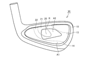
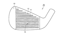
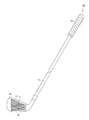
- FIG. 1 is a schematic rear view of an iron golf club head according to an embodiment of the present invention. It is a schematic front view of the iron golf club head in one embodiment of the present invention. It is a schematic front view of the iron golf club in one embodiment of the present invention.
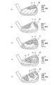
- FIG. 2 is a diagram showing primary to fifth vibration modes of the iron golf club head in the present embodiment, and is a diagram showing a primary vibration mode (A), a diagram showing a secondary vibration mode (B),
- FIG. 4C is a diagram showing a third-order vibration mode,
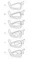
- FIG. 4D is a diagram showing a fourth-order vibration mode, and FIG. It is a schematic rear view of the iron golf club head of a comparative example and an example of the present invention.
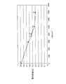
- FIG. 6 is a graph showing the ratio of sound pressure in inventive examples 1 to 4 relative to comparative examples 1 and 2. It is a figure which shows the relationship between A correction
- the iron golf club head 30 mainly has a head portion 10 and a badge portion 20 attached to the head portion 10.
- the head unit 10 has a face surface 11 that is a ball striking surface.
- a plurality of grooves 12 are formed on the face surface 11.
- the plurality of groove portions (score lines) 12 are formed at substantially equal intervals in the direction of longitudinally cutting the face surface 11, and are formed linearly in the direction crossing the face surface 11.
- the head portion 10 also has a hosel portion to which a shaft is connected.
- the head portion 10 also has a top edge portion, a toe portion, a sole portion, and a heel portion located around the face surface 11.
- a top edge part is a part which comprises the upper end edge part of the head part 10 main body from a hosel part to a toe part.
- a sole part is a part which comprises the bottom part of the head part 10 main body.
- the toe portion is a portion that connects the top edge portion and the sole portion on the side away from the hosel portion.
- the heel part is a part from the lower end of the hosel part to the sole part.
- the head unit 10 has a back surface 13 located behind the face surface 11 (back surface).
- a cavity standing surface 14 is formed on the back surface of the face surface 11 so as to surround a peripheral end portion thereof, and the back surface 13 is a region surrounded by the cavity standing surface 14.
- the badge part 20 is affixed on the back surface 13 of the head part 10 by specifying its size or range.
- a material of the badge part 20 aluminum, stainless steel, brass, ABS, nickel, magnesium or the like can be applied.
- the badge part 20 can be produced using a material including, for example, JIS standard SUS304.
- the badge part 20 is affixed on the back surface 13.
- the badge part 20 may be affixed on the back surface 13 with a double-sided tape, for example.
- the badge part 20 is affixed to the first maximum amplitude region 21 having the largest amplitude in the fourth-order vibration mode of the back surface 13.
- Each vibration mode is a vibration mode (natural mode) at each natural frequency (natural frequency). Therefore, the fourth-order vibration mode is a vibration mode at a fourth-order eigenvalue. The region having the largest amplitude in the vibration mode vibrates most.
- the badge unit 20 includes a first maximum amplitude region 21 having the largest amplitude in the fourth-order vibration mode of the back surface 13 and a second maximum amplitude region 23 having the largest amplitude in the fifth-order vibration mode (see FIG. 4E). What is necessary is just to be affixed on at least one of these.
- the first small amplitude region 22 whose amplitude in the fourth-order vibration mode is smaller than the first maximum amplitude region 21 is arranged around the first maximum amplitude region 21 so as to define the first maximum amplitude region 21. As indicated by a region R in FIG. 1, the badge portion 20 is preferably attached so as not to overlap the first small amplitude region 22.
- a second small amplitude region 24 (see FIG. 4E) whose amplitude in the fifth-order vibration mode is smaller than the second maximum amplitude region 23 is arranged around the second maximum amplitude region 23 so as to define the second maximum amplitude region 23. ing.
- the badge part 20 should just be affixed so that it may not overlap with at least one of the 1st small amplitude area
- the area A2 of the back surface 13 to which the badge part 20 is attached may be 38.6% or more and 40.9% or less of the area A1 of the entire back surface 13.
- the total area A1 of the back surface 13 is the area of the back surface 13 surrounded by the cavity standing surface 14.
- the restitution coefficient of the head unit 10 may be 0.8 or more.
- the head unit 10 is highly repulsive.
- a method for measuring the coefficient of restitution will be described.
- the speed of the golf ball before the collision when the golf ball collides with the center of the score line or the sweet spot position with the face surface 11 of the iron golf club head 30 oriented perpendicularly to the ground and the golf ball to be collided (Vin) and the speed (Vout) of the golf ball after the collision are measured by a speed measuring device having an optical sensor. Vin is 40.5 ⁇ 0.5 m / s.
- the restitution coefficient COR is measured by the following equation (1) from the measured Vin and Vout, the mass M of the iron golf club head 30, and the mass m of the golf ball.
- Vout / Vin (COR ⁇ M ⁇ m) / (M + m) (1)
- Pinnacle Gold LS sold by ACUSHINET COMPANY is used.
- the average weight of the golf ball is 45.4 ⁇ 0.4 grams, and the golf ball is stored in a room kept at 23 ⁇ 1 ° C. during the measurement.
- the head unit 10 can be manufactured using a material including, for example, JIS standard S25C. Moreover, as a material of the head part 10, spring steel, maraging steel, stainless steel, etc. may be applied. In addition, the head part 10 can also be produced by forging.
- the head portion 10 may be plated.
- the plating may be, for example, Ni (nickel) -Cr (chromium) plating.
- an iron golf club 50 is configured by combining a shaft 51 and a grip 52 with an iron golf club head 30.
- the iron golf club 50 includes a shaft 51, a grip 52 attached to one end of the shaft 51, and an iron golf club head 30 attached to the other end opposite to the grip 52 of the shaft 51.
- shafts 51 and grips 52 can be employed.
- the present inventors have placed the badge portion 20 on at least one of the first maximum amplitude region 21 having the largest amplitude in the fourth-order vibration mode of the back surface 13 and the second maximum amplitude region 23 having the largest amplitude in the fifth-order vibration mode.
- the present inventors have placed the badge portion 20 on at least one of the first maximum amplitude region 21 having the largest amplitude in the fourth-order vibration mode of the back surface 13 and the second maximum amplitude region 23 having the largest amplitude in the fifth-order vibration mode.
- the badge part 20 is affixed by specifying a size or a range rather than a wide area like the entire back surface 13, it is possible to suppress a reduction in the sounding time of the hitting sound. That is, since the size or range of the area A2 of the back surface 13 to which the badge portion 20 is attached is limited, it is possible to suppress a reduction in the sounding time of the hitting sound.
- the ball is hit by lowering the sound pressure in at least one of the fourth and fifth vibration modes while suppressing a reduction in the sounding time of the hitting sound. Sound can be improved to improve the hit feeling.
- the badge portion 20 is attached so as not to overlap at least one of the first small amplitude region 22 and the second small amplitude region 24.
- the area A2 of the back surface 13 to which the badge portion 20 is attached is 38.6% or more and 40.9% or less of the entire area A1 of the back surface 13. Preferably there is. Thereby, the fall of the reverberation time of the hitting sound can be further effectively suppressed.
- the restitution coefficient of the head portion 10 is preferably 0.8 or more. Thereby, a hit feeling can be improved, achieving high resilience.
- the iron golf club 50 includes the above-described iron golf club head 30, thereby suppressing at least one of fourth-order and fifth-order vibrations while suppressing a reduction in the sounding time of the hitting sound. By reducing the sound pressure in the mode, the iron golf club 50 that can improve the hitting sound and improve the hit feeling can be obtained.
- each vibration mode of the iron golf club head of the present embodiment will be described.
- Each vibration mode was analyzed in a free state of the head alone using eigenvalue analysis software Pro / Mechanica manufactured by PTC.
- Each eigenvalue was also analyzed using the eigenvalue analysis software Pro / Mechanica.
- the legend level of each vibration mode is indicated by 9. At this time, the number of legends displayed is 10.
- FIG. 4 is a diagram showing a vibration mode in which only the next back surface is extracted.
- the amplitude of the vibration mode of the entire head is represented in 10 steps, levels 1 and 2 are small, level 3 is medium, and level 4 and above are large. Since the vicinity of levels 1 to 4 appears mainly on the back surface, the above display is used. Note that the maximum amplitude of the vibration mode of the entire head appears mainly in the hosel part and the top edge part. Therefore, the first maximum amplitude region 21 of the back surface 13 is represented by level 4 or higher. Similarly, the second maximum amplitude region 23 of the back surface 13 is also represented by level 4 or higher.
- each vibration mode in a state where the badge portion 20 is not attached is shown.
- the vibration modes at the first to fifth eigenvalues there are an abdomen and a node, respectively.
- the abdomen is where the amplitude is the largest, and the node is the smallest. Since the vibration modes in the first to fifth eigenvalues are different from each other, the positions of the abdomen and the node are different from each other.
- This example is a model with a uniform face thickness, and the partial thickness model can be in different vibration modes.
- the vibration mode is almost the same. does not change.
- the abdomen is located around the connecting portion between the top edge portion and the toe portion on the back surface 13 of the head portion 10.
- the primary eigenvalue is 2969 Hz.
- the abdomen is located around the hosel portion side portion of the top edge portion on the back surface 13 of the head portion 10.
- the secondary eigenvalue is 3913 Hz.
- the abdomen is located around the central portion of the top edge portion on the back surface 13 of the head portion 10.
- the third order eigenvalue is 5515 Hz.
- the abdomen is located on the back surface 13 of the head unit 10 in the region extending from the periphery of the center portion of the top edge portion to the center portion of the back surface 13. ing. That is, the first maximum amplitude region 21 is located in a region from the periphery of the central portion of the top edge portion to the central portion of the back surface 13. The area of the first maximum amplitude region (fourth-order maximum amplitude region) 21 is approximately 350 mm 2 . And the 1st small amplitude area
- region 22 is located in the circumference
- the fourth order eigenvalue is 6388 Hz.
- the area of the second maximum amplitude region (5th order maximum amplitude region) 23 is approximately 500 mm 2 in total. And the 2nd small amplitude area
- region 24 is located in the circumference
- the fifth order eigenvalue is 9785 Hz.
- the measurement of sound pressure and reverberation time was performed as follows. In the laboratory, a hit point 15 (see FIG. 2) between the third and fourth points was hit from the sole part side of the score line with a pendulum screw hammer, and the sound was recorded. Sound pressure and reverberation time were measured for a single head.
- the measuring device used was TASCAM HD-P2.
- the software used was Bruel & Kjar Sound Quality Type 7698.
- the microphone was Bruel & Kjar Microphone Type 4190.
- the microphone power source was Bruel & Kjar Microphone Type 2804.
- the calibrator used was Bruel & Kjar Sound Level Calibrator Type 4231.
- the distance between the hit point 15 and the microphone was 20 cm, the measurement time was -0.2 to 1.8 seconds, and the window function was "Rectangular".
- the maximum time of instantaneous sound pressure is 0 seconds.
- Three balls were recorded, and the sound pressure was set at an intermediate value.
- the reverberation time was calculated as the time until the sound pressure finally fell below 0.05 Pa.
- FIGS. 5A to 5F the configurations of the iron golf club heads 30 of Comparative Examples A and B and Invention Examples C to F will be described.
- the badge portion 20 is not attached to the back surface 13 of the head portion 10.
- the badge portion 20 is attached to the back surface 13 of the head portion 10. Yes.
- the back surface 13 of the head portion 10 is not covered with the badge portion 20.
- the badge portion 20 is pasted along the outer peripheral shape of the back surface 13 so as to cover almost the entire region on the center side of the back surface 13. It has been.
- the badge unit 20 is affixed to the back surface 13 so as to cover most of the back surface 13.
- the badge portion 20 is provided so as to cover the abdomen of the vibration mode at the eigenvalue of at least one of the fourth and fifth orders. Is pasted.
- the badge part 20 is attached so as to cover the abdomen of the vibration mode of the fourth-order eigenvalue. More specifically, the badge part 20 is affixed so that the area
- the area where the badge part 20 of the invention sample C covers the first maximum amplitude region (fourth-order maximum amplitude region) 21 is approximately 300 mm 2 .
- the ratio of the area where the badge portion 20 of Example C of the invention covers the first maximum amplitude region (fourth-order maximum amplitude region) 21 is 85.7%.
- the badge part 20 is attached so as to cover the abdomen of the vibration mode of the fifth order natural value. More specifically, a region extending from the periphery of the hosel portion side portion of the top edge portion to the central portion of the back surface 13 and a region extending from the periphery of the top edge portion portion of the top edge portion to the central portion of the back surface 13 are covered.
- the badge part 20 is affixed.
- the area where the badge part 20 of the invention sample D covers the second maximum amplitude region (fifth maximum amplitude region) 23 is approximately 360 mm 2 .
- the ratio of the area where the badge part 20 of Example D of the invention covers the second maximum amplitude region (5th order maximum amplitude region) 23 is 72.0%.
- the badge part 20 is attached so as to cover the abdomen of the vibration mode of the fourth-order eigenvalue. More specifically, the badge part 20 is affixed so that the area
- the invention example E has a smaller area of the badge part 20.
- the area where the badge portion 20 of the invention sample E covers the first maximum amplitude region (fourth-order maximum amplitude region) 21 is approximately 250 mm 2 .
- the ratio of the area in which the badge part 20 of Example E of the present invention covers the first maximum amplitude region (fourth-order maximum amplitude region) 21 is 71.4%.
- the badge part 20 is attached so as to cover the abdominal part of the vibration mode of the fourth order natural value. More specifically, the badge portion 20 is formed so as to cover a region extending from the periphery of the central portion of the top edge portion to the central portion of the back surface 13 and a region extending from the central portion of the back surface 13 to the sole portion side portion of the toe portion. It is pasted.
- the invention example F has a smaller area of the badge part 20.
- the invention example F has a larger area of the badge portion 20.
- the badge part 20 of the present invention example covers at least 70% of the area of the first maximum amplitude region (fourth order maximum amplitude region) 21 or the area of the second maximum amplitude region (fifth order maximum amplitude region) 23. preferable.
- the badge unit 20 of the present invention example covers at least 85% of the area of the first maximum amplitude region (fourth order maximum amplitude region) 21 or the area of the second maximum amplitude region (fifth order maximum amplitude region) 23. Further preferred.
- the sound pressure (dB) of the fourth vibration mode (4th) is smaller in the inventive examples C, E and F than in the comparative example A.
- Inventive Example C has a lower sound pressure in the fourth vibration mode than Inventive Example D. From this, it was confirmed that the sound pressure in the fourth-order vibration mode can be particularly lowered by attaching the badge part 20 to the abdomen of the fourth-order vibration mode.
- Inventive Examples E and F have higher sound pressure than Inventive Example C.
- the respective sound pressure ratios (%) compared with the sound pressure in the fourth-order vibration mode of Comparative Example A were 72.1% or more and 84.5% or less.
- the sound pressure of the fifth vibration mode (5th) is smaller in the inventive example D than in the comparative example A.
- Inventive Example D has a lower sound pressure in the fifth vibration mode than Inventive Examples C, E, and F. From this, it was confirmed that the sound pressure in the fifth vibration mode can be particularly lowered by sticking the badge part 20 to the abdomen of the fifth vibration mode.
- the sound pressure ratio (%) compared to the sound pressure in the fifth-order vibration mode of Comparative Example A was 79.3%.
- Examples C to F of the present invention can suppress a decrease in the reverberation time.
- the respective reverberation time ratio (%) compared with the reverberation time of the comparative example A was 49.0% or more and 71.3% or less.
- Inventive Examples E and F have a longer reverberation time than Inventive Example C. From this, it was confirmed that the reverberation time can be lengthened by reducing the area A2 of the back surface 13 to which the badge part 20 is attached.
- the area A2 of the back surface 13 to which the badge portion 20 is attached is 800 mm.
- the badge part 20 was affixed so that it might become two .
- the ratio (A2 / A1) of the area A2 (mm 2 ) of the back surface 13 where the badge portion 20 is attached to the area A1 (mm 2 ) of the entire back surface 13 is 38.6% or more and 40.9% or less. became.
- Invention Examples 1 to 4 are average values of values measured three times.
- the badge part 20 is attached to the abdomen of the fourth-order vibration mode with a double-sided tape.
- the thickness of the double-sided tape is 0.4 mm.
- the thickness of the double-sided tape is 0.8 mm.
- the badge part 20 is affixed to the abdomen of the fifth vibration mode with a double-sided tape.
- the thickness of the double-sided tape is 0.4 mm.
- the thickness of the double-sided tape is 0.8 mm.
- the sound pressure in the vibration mode at the first to sixth eigenvalues of Examples 1 to 4 of the present invention is lower than the sound pressure when the badge part 20 is not attached. is doing.
- the sound pressures of the inventive examples 1 and 2 are particularly reduced. From this, it was confirmed that the sound pressure in the fourth-order vibration mode can be particularly lowered by attaching the badge part 20 to the abdomen of the fourth-order vibration mode.
- the sound pressure ratio (%) of the present invention example 1 is 75.0%, and the sound pressure of the present invention example 2 The pressure ratio (%) is 70.6%. It was found that the sound pressure was lower in Invention Example 2 where the thickness of the double-sided tape was thicker than in Invention Example 1.
- the sound pressures of Invention Example 3 and Invention Example 4 are reduced. From this, it was confirmed that the sound pressure in the fifth vibration mode can be particularly lowered by sticking the badge part 20 to the abdomen of the fifth vibration mode.
- the fourth example of the present invention is 82.5% compared to the sound pressure when the badge part 20 is not attached. It was found that the sound pressure was lower in Invention Example 2 where the thickness of the double-sided tape was thicker than in Invention Example 1.
- the sound pressure in at least one of the fourth and fifth vibration modes can be reduced particularly by attaching the badge part 20 to the abdomen of the fourth and fifth vibration modes.
- Comparative Example 1 is a comparative example in the fourth-order vibration mode, and the badge portion 20 is not attached.
- the area A2 of the back surface 13 to which the badge part 20 of Invention Example 1 and Invention Example 2 is attached is 553 mm 2 .
- the A corrected sound pressure (A-wt) of Invention Example 1 and Invention Example 2 was lower than the A correction sound pressure of Comparative Example 1.
- Example 1 of the present invention is 68.5 (dB)
- Example 2 of the present invention is 67.0 (dB).
- Example 1 of the present invention is 0.575 seconds, which is 63.1% of Comparative Example 1, and Example 2 of the present invention is 0.497 seconds, which is 54.6% of Comparative Example 1. is there.
- Comparative example 2 is a comparative example of the fifth-order vibration mode, and the badge portion 20 is not attached.
- the area A2 where the badge part 20 of the present invention examples 3 and 4 is affixed is 820 mm 2 .
- the A correction sound pressures of the inventive examples 3 and 4 were lower than the A correction sound pressure of the comparative example 2.
- Example 3 of the present invention is 70.1 (dB)
- Example 4 of the present invention is 67.6 (dB).
- the third example of the present invention was 0.609 seconds, which was 59.3% of the second comparative example, and the fourth example of the present invention was 0.553 seconds, which was 53.8% of the second comparative example. is there.
- the inventors of the present application produced two types of iron golf clubs 50 each having a badge portion 20 attached to the abdomen of the fourth and fifth vibration modes, and each of them was composed of four female professionals.
- a test hit test by a golfer was conducted. All the female professional golfers who performed the trial hit test determined that the hit feeling of the two types of iron golf clubs 50 was good. Also from this fact, it was found that the feeling of hitting can be improved by attaching the badge part 20 to the abdomen of at least one of the fourth and fifth vibration modes.
- the present invention can be particularly advantageously applied to an iron golf club head and an iron golf club in which a badge portion is attached to the head portion.
Landscapes
- Health & Medical Sciences (AREA)
- General Health & Medical Sciences (AREA)
- Physical Education & Sports Medicine (AREA)
- Golf Clubs (AREA)
Abstract
アイアンゴルフクラブヘッド(30)は、ヘッド部(10)と、ヘッド部(10)に貼り付けられたバッジ部(20)とを備えている。ヘッド部(10)は、フェース面(11)と、フェース面(11)の後方に位置するバック面(13)とを含んでいる。バック面(13)の4次の振動モードにおける振幅が最も大きい第1最大振幅領域(21)および5次の振動モードにおける振幅が最も大きい第2最大振幅領域(23)の少なくとも一方にバッジ部(20)が貼り付けられている。これにより、打球音の響き時間の低下を抑制しつつ打球音の音圧を下げることで打球音を向上させて打感を向上することができるアイアンゴルフクラブヘッドおよびアイアンゴルフクラブを得ることができる。
Description
本発明は、アイアンゴルフクラブヘッドおよびアイアンゴルフクラブに関し、特に、ヘッド部にバッジ部が貼り付けられたアイアンゴルフクラブヘッドおよびアイアンゴルフクラブに関する。
最近のゴルフクラブにおいては、ウッドゴルフクラブだけではなくアイアンゴルフクラブにおいても高反発化が求められている。アイアンゴルフクラブを高反発化するためにフェースを薄肉にすることが提案されている。フェースを薄肉にするとフェースのたわみが大きくなるため、フェースから発生する打球音が大きくなる。近年の研究において、アイアンゴルフクラブの打感は打球音の影響を受けることが分かっており、打球音が大きくなると打感が低下すると感じるゴルファがあることも分かっている。また、打球音の響き時間が長いと打感が向上し、打球音の響き時間が短いと打感が低下すると感じるゴルファがあることも分かっている。
他方、たとえば特開2010-148565号公報(特許文献1)には、被着体がバック面に接着されたゴルフクラブヘッドが開示されている。この被着体は打球時に発生する振動を吸収し得る。この被着体はバック面の平面形状を縮小した形状を有しており、バック面の中央部に接着されている。
上記公報のゴルフクラブヘッドでは、被着体がバック面の中央部を大きく覆っているため、打球時に発生する振動が大きく吸収される。これにより、打球音の大きさ(音圧)が大きく低下する。しかしながら、打球音の大きさ(音圧)とともに打球音の響き時間も大きく低下する。したがって、打球音の響き時間が低下するために打感が低下する。
本発明は上記課題を鑑みてなされたものであり、その目的は、打球音の響き時間の低下を抑制しつつ打球音の音圧を下げることで打球音を向上させて打感を向上することができるアイアンゴルフクラブヘッドおよびアイアンゴルフクラブを提供することである。
本発明のアイアンゴルフクラブヘッドは、ヘッド部と、ヘッド部に貼り付けられたバッジ部とを備えている。ヘッド部は、フェース面と、フェース面の後方に位置するバック面とを含んでいる。バック面の4次の振動モードにおける振幅が最も大きい第1最大振幅領域および5次の振動モードにおける振幅が最も大きい第2最大振幅領域の少なくとも一方にバッジ部が貼り付けられている。
本発明者等が鋭意検討した結果、ヘッド部の4次および5次の振動モードにおける音圧が打感に影響することを見出した。つまり、4次および5次の振動モードにおける音圧を下げると打球音が向上して打感が向上することがわかった。4次および5次の振動モードにおける振幅が最も大きい領域で4次および5次の振動モードにおける音圧は最も大きくなる。そこで、上記のように本発明者等は、バック面の4次の振動モードにおける振幅が最も大きい第1最大振幅領域および5次の振動モードにおける振幅が最も大きい第2最大振幅領域の少なくとも一方にバッジ部が貼り付けられていることによって、ヘッド部の4次および5次の少なくともいずれかの振動モードにおける音圧を下げることで、打球音を向上させて打感を向上することができるという知見を得た。
また、バッジ部は、バック面全体のように広いエリアではなく、大きさまたは範囲を特定して貼り付けられているため、打球音の響き時間の低下を抑制することができる。
よって、本発明のアイアンゴルフクラブヘッドによれば、打球音の響き時間の低下を抑制しつつ4次および5次の少なくともいずれかの振動モードにおける音圧を下げることで打球音を向上させて打感を向上することができる。
上記のアイアンゴルフクラブヘッドでは、好ましくは、第1最大振幅領域を規定するようにその周囲に配置され、4次の振動モードにおける振幅が第1最大振幅領域よりも小さい第1小振幅領域と、第2最大振幅領域を規定するようにその周囲に配置され、5次の振動モードにおける振幅が第2最大振幅領域よりも小さい第2小振幅領域とをさらに備えている。第1小振幅領域および第2小振幅領域の少なくとも一方と重ならないようにバッジ部が貼り付けられている。これにより、不必要に打球音の響き時間が低下することを抑制することができる。つまり、打球音の響き時間の低下を最小化することができる。そのため、打球音の響き時間の低下をさらに効果的に抑制することができる。
上記のアイアンゴルフクラブヘッドでは、好ましくは、バッジ部が貼り付けられたバック面の面積は、バック面全体の面積の38.6%以上40.9%以下である。これにより、打球音の響き時間の低下をさらに効果的に抑制することができる。
上記のアイアンゴルフクラブヘッドでは、好ましくは、ヘッド部の反発係数は0.8以上である。これにより、高反発化を実現しつつ打感を向上することができる。
本発明のアイアンゴルフクラブは、シャフトと、シャフトの一方端に取り付けられたグリップと、シャフトのグリップと反対側の他方端に取り付けられた上述のアイアンゴルフクラブヘッドとを備えている。これにより、打球音の響き時間の低下を抑制しつつ4次および5次の少なくともいずれかの振動モードにおける音圧を下げることで打球音を向上させて打感を向上することができるアイアンゴルフクラブを得ることができる。
以上説明したように、本発明のアイアンゴルフクラブヘッドおよびアイアンゴルフクラブによれば、打球音の響き時間の低下を抑制しつつ打球音の音圧を下げることで打球音を向上させて打感を向上することができる。
以下、本発明の一実施の形態について図に基づいて説明する。
最初に本発明の一実施の形態のアイアンゴルフクラブヘッドの構成について説明する。
最初に本発明の一実施の形態のアイアンゴルフクラブヘッドの構成について説明する。
図1および図2を参照して、アイアンゴルフクラブヘッド30は、ヘッド部10と、ヘッド部10に貼り付けられたバッジ部20とを主に有している。ヘッド部10は、打球面であるフェース面11を有している。フェース面11に複数の溝部12が形成されている。複数の溝部(スコアライン)12は、フェース面11を縦断する方向に略等間隔で形成されており、フェース面11を横断する方向に直線状に形成されている。
ヘッド部10は、シャフトが接続されるホーゼル部も有している。ヘッド部10は、フェース面11の周囲に位置するトップエッジ部、トゥ部、ソール部、ヒール部も有している。トップエッジ部はホーゼル部からトゥ部に至るヘッド部10本体の上端縁部を構成する部分である。ソール部は、ヘッド部10本体の底部を構成する部分である。トゥ部はホーゼル部から離れた側のトップエッジ部とソール部とを接続する部分である。ヒール部はホーゼル部下端からソール部に至る部分である。
ヘッド部10は、フェース面11の後方(背面)に位置するバック面13を有している。フェース面11の背面には、その周辺端部を囲むようにキャビティ立ち面14が形成されており、バック面13はこのキャビティ立ち面14に囲まれた領域である。
バッジ部20は、その大きさまたは範囲を特定してヘッド部10のバック面13に貼り付けられている。バッジ部20の材料としては、アルミニウム、ステンレス、真鍮、ABS、ニッケル、マグネシウムなどが適用され得る。バッジ部20は、たとえばJIS規格SUS304を含む素材を用いて作製することができる。バック面13にバッジ部20が貼り付けられている。バッジ部20はバック面13にたとえば両面テープで貼り付けられていてもよい。バッジ部20は、バック面13の4次の振動モードにおける振幅が最も大きい第1最大振幅領域21に貼り付けられている。
各次の振動モードとは、各次の固有値(固有振動数)における振動モード(固有モード)である。よって、4次の振動モードとは、4次の固有値における振動モードである。振動モードにおける振幅が最も大きい領域が最も大きく振動している。
バッジ部20は、バック面13の4次の振動モードにおける振幅が最も大きい第1最大振幅領域21および5次の振動モードにおける振幅が最も大きい第2最大振幅領域23(図4(E)参照)の少なくとも一方に貼り付けられていればよい。
4次の振動モードにおける振幅が第1最大振幅領域21よりも小さい第1小振幅領域22が第1最大振幅領域21を規定するようにその周囲に配置されている。図1中の領域Rで示すように、バッジ部20は、第1小振幅領域22に重ならないように貼り付けられていることが好ましい。
また、5次の振動モードにおける振幅が第2最大振幅領域23よりも小さい第2小振幅領域24(図4(E)参照)が第2最大振幅領域23を規定するようにその周囲に配置されている。
バッジ部20は、第1小振幅領域22および第2小振幅領域24の少なくとも一方と重ならないように貼り付けられていればよい。
バッジ部20が貼り付けられたバック面13の面積A2は、バック面全体13の面積A1の38.6%以上40.9%以下であってもよい。バック面13全体の面積A1は、バック面13においてキャビティ立ち面14で囲まれた部分の面積である。
ヘッド部10の反発係数は0.8以上であってもよい。反発係数が0.8以上の場合、ヘッド部10は高反発である。ここで、反発係数の測定方法について説明する。アイアンゴルフクラブヘッド30のフェース面11が地面および衝突させるゴルフボールに対して垂直に向けられた状態で、ゴルフボールがスコアラインの中央またはスイートスポット位置に衝突した際の衝突前のゴルフボールのスピード(Vin)と衝突後のゴルフボールのスピード(Vout)とが光学式センサーを有する速度測定器で測定される。Vinは、40.5±0.5m/sである。
測定されたVinおよびVoutと、アイアンゴルフクラブヘッド30の質量Mと、ゴルフボールの質量mとから次の式(1)により反発係数CORが測定される。
Vout/Vin=(COR×M-m)/(M+m) ・・・(1)
なお、ゴルフボールとしては、ACUSHINET COMPANYより販売のピナクル・ゴールド(Pinnacle Gold LS)が使用される。ゴルフボールの平均重量は45.4±0.4グラムであり、測定中、ゴルフボールは23±1℃に保った室内に保管される。
なお、ゴルフボールとしては、ACUSHINET COMPANYより販売のピナクル・ゴールド(Pinnacle Gold LS)が使用される。ゴルフボールの平均重量は45.4±0.4グラムであり、測定中、ゴルフボールは23±1℃に保った室内に保管される。
ヘッド部10は、たとえばJIS規格S25Cを含む素材を用いて作製することができる。また、ヘッド部10の材料としては、ばね鋼、マレージング鋼、ステンレス鋼などが適用され得る。なお、ヘッド部10は、鍛造により作製することもできる。
また、ヘッド部10にはめっきが施されていてもよい。めっきは、たとえば、Ni(ニッケル)-Cr(クロム)めっきであってもよい。
図3を参照して、アイアンゴルフクラブヘッド30にシャフト51およびグリップ52を組み合わせることでアイアンゴルフクラブ50が構成される。アイアンゴルフクラブ50は、シャフトと51、シャフト51の一方端に取り付けられたグリップ52と、シャフト51のグリップ52と反対側の他方端に取り付けられたアイアンゴルフクラブヘッド30とを有している。なお、シャフト51およびグリップ52は周知のものを採用可能である。
次に、本発明の一実施の形態の作用効果について説明する。
本発明者等は、バック面13の4次の振動モードにおける振幅が最も大きい第1最大振幅領域21および5次の振動モードにおける振幅が最も大きい第2最大振幅領域23の少なくとも一方にバッジ部20が貼り付けられていることによって、ヘッド部10の4次および5次の少なくともいずれかの振動モードにおける音圧を下げることで、打球音を向上させて打感を向上することができるという知見を得た。
本発明者等は、バック面13の4次の振動モードにおける振幅が最も大きい第1最大振幅領域21および5次の振動モードにおける振幅が最も大きい第2最大振幅領域23の少なくとも一方にバッジ部20が貼り付けられていることによって、ヘッド部10の4次および5次の少なくともいずれかの振動モードにおける音圧を下げることで、打球音を向上させて打感を向上することができるという知見を得た。
また、バッジ部20は、バック面13全体のように広いエリアではなく、大きさまたは範囲を特定して貼り付けられているため、打球音の響き時間の低下を抑制することができる。つまり、バッジ部20が貼り付けられたバック面13の面積A2の大きさまたは範囲が限定されているので、打球音の響き時間の低下を抑制することができる。
よって、本発明の一実施の形態のアイアンゴルフクラブヘッド30によれば、打球音の響き時間の低下を抑制しつつ4次および5次の少なくともいずれかの振動モードにおける音圧を下げることで打球音を向上させて打感を向上することができる。
本発明の一実施の形態のアイアンゴルフクラブヘッド30では、第1小振幅領域22および第2小振幅領域24の少なくとも一方と重ならないようにバッジ部20が貼り付けられていることが好ましい。これにより、不必要に打球音の響き時間が低下することを抑制することができる。つまり、打球音の響き時間の低下を最小化することができる。そのため、打球音の響き時間の低下をさらに効果的に抑制することができる。
本発明の一実施の形態のアイアンゴルフクラブヘッド30では、バッジ部20が貼り付けられたバック面13の面積A2は、バック面13全体の面積A1の38.6%以上40.9%以下であることが好ましい。これにより、打球音の響き時間の低下をさらに効果的に抑制することができる。
本発明の一実施の形態のアイアンゴルフクラブヘッド30では、ヘッド部10の反発係数は0.8以上であることが好ましい。これにより、高反発化を実現しつつ打感を向上することができる。
本発明の一実施の形態のアイアンゴルフクラブ50は、上述のアイアンゴルフクラブヘッド30を備えていることにより、打球音の響き時間の低下を抑制しつつ4次および5次の少なくともいずれかの振動モードにおける音圧を下げることで打球音を向上させて打感を向上することができるアイアンゴルフクラブ50を得ることができる。
以下、本発明の実施例について説明する。なお、上記と同一または相当する部分に同一の参照符号を付し、その説明を繰り返さない場合がある。
まず、本実施例のアイアンゴルフクラブヘッドの各振動モードについて説明する。
各振動モードは、PTC社製の固有値解析ソフトウェアPro/Mechanicaを用いてヘッド単体のフリー状態で解析を行った。また、各次の固有値も上記固有値解析ソフトウェアPro/Mechanicaを用いて解析を行った。各振動モードの凡例レベルは9で表示している。この時、表示される凡例数は10となる。
各振動モードは、PTC社製の固有値解析ソフトウェアPro/Mechanicaを用いてヘッド単体のフリー状態で解析を行った。また、各次の固有値も上記固有値解析ソフトウェアPro/Mechanicaを用いて解析を行った。各振動モードの凡例レベルは9で表示している。この時、表示される凡例数は10となる。
図4は各次のバック面のみを抽出した振動モードを表す図である。ヘッド全体の振動モードの振幅を10段階で表し、レベル1、2を小、レベル3を中、レベル4以上を大で表している。バック面においては主にレベル1から4付近が現れる為、上記表示としている。なおヘッド全体の振動モードの最大振幅は主にホーゼル部やトップエッジ部に現れる。よってバック面13の第1最大振幅領域21はレベル4以上で表している。またバック面13の第2最大振幅領域23も同様にレベル4以上で表している。
図4(A)~(E)を参照して、本実施例のアイアンゴルフクラブヘッド30において、バッジ部20が貼り付けられていない状態の各振動モードを示す。1次~5次の固有値における振動モードでは、それぞれ腹部と節部とがある。腹部は振幅が最も大きいところであり、節部は最も小さいところである。1次~5次の固有値における振動モードは、それぞれ異なっているため、腹部および節部の位置はそれぞれ異なっている。
本実施例は、フェース肉厚均一のモデルであり、部分肉厚モデルは異なる振動モードになりえるが、肉厚の最大-最小の肉厚差が0.5mm以下のモデルでは、振動モードがほとんど変わらない。
図4(A)を参照して、1次の固有値における振動モードでは、ヘッド部10のバック面13において、トップエッジ部とトゥ部との連結部分周辺に腹部が位置している。1次の固有値は2969Hzである。
図4(B)を参照して、2次の固有値における振動モードでは、ヘッド部10のバック面13において、トップエッジ部のホーゼル部側部分周辺に腹部が位置している。2次の固有値は3913Hzである。
図4(C)を参照して、3次の固有値における振動モードでは、ヘッド部10のバック面13において、トップエッジ部の中央部分周辺に腹部が位置している。3次の固有値は5515Hzである。
図4(D)を参照して、4次の固有値における振動モードでは、ヘッド部10のバック面13において、トップエッジ部の中央部分周辺からバック面13の中央部分に至る領域に腹部が位置している。つまり、第1最大振幅領域21がトップエッジ部の中央部分周辺からバック面13の中央部分に至る領域に位置している。第1最大振幅領域(4次最大振幅領域)21の面積は、略350mm2である。そして、第1最大振幅領域21を規定するようにその周囲に第1小振幅領域22が位置している。4次の固有値は6388Hzである。
図4(E)を参照して、5次の固有値における振動モードでは、ヘッド部10のバック面13において、トップエッジ部のホーゼル部側部分周辺からバック面13の中央部分に至る領域と、トップエッジ部のトゥ部側部分周辺からバック面13の中央部分に至る領域とに腹部が位置している。つまり、第2最大振幅領域23がトップエッジ部のホーゼル部側部分周辺からバック面13の中央部分に至る領域と、トップエッジ部のトゥ部側部分周辺からバック面13の中央部分に至る領域とに位置している。第2最大振幅領域(5次最大振幅領域)23の面積は、合計で略500mm2である。そして、第2最大振幅領域23を規定するようにその周囲に第2小振幅領域24が位置している。5次の固有値は9785Hzである。
次に、比較例A、Bおよび本発明例C~Fのアイアンゴルフクラブの音圧および響き時間について説明する。
音圧および響き時間の測定は次のように行った。実験室内において振り子式ネジハンマーでスコアラインのソール部側から3本目と4本目との間の打点15(図2参照)を打撃し、その音を録音した。音圧および響き時間はヘッド単体について測定した。測定器はTASCAM HD-P2を使用した。ソフトウエアはBruel & Kjar Sound Quality Type 7698を使用した。マイクはBruel & Kjar Microphone Type 4190を使用した。マイク電源はBruel & Kjar Microphone Type 2804を使用した。キャリブレーターはBruel & Kjar Sound Level Calibrator Type 4231を使用した。打点15とマイクとの距離は20cmとし、測定時間は-0.2~1.8秒とし、窓関数は「Rectangular」とした。ここで瞬時音圧の最大時刻が0秒である。それぞれ3球録音し音圧が中間の値を採用した。響き時間は、音圧が0.05Paを最後に切るまでの時間で算出した。
図5(A)~(F)を参照して、比較例A、Bおよび本発明例C~Fのアイアンゴルフクラブヘッド30の構成について説明する。図5(A)を参照して、比較例Aのアイアンゴルフクラブヘッド30ではヘッド部10のバック面13にバッジ部20が貼り付けられていない。一方、図5(B)~(F)を参照して、比較例Bおよび本発明例C~Fのアイアンゴルフクラブヘッド30では、ヘッド部10のバック面13にバッジ部20が貼り付けられている。
図5(A)を参照して、比較例Aのアイアンゴルフクラブヘッド30では、ヘッド部10のバック面13がバッジ部20で覆われていない。
図5(B)を参照して、比較例Bのアイアンゴルフクラブヘッド30では、バック面13の外周形状に沿って、バック面13の中央側のほぼ全域を覆うようにバッジ部20が貼り付けられている。バッジ部20は、バック面13の大部分を覆うようにバック面13に貼り付けられている。
図5(C)~(F)に示すように、本発明例C~Fのアイアンゴルフクラブヘッド30では4次および5次の少なくともいずれかの固有値における振動モードの腹部を覆うようにバッジ部20が貼り付けられている。
図5(C)を参照して、本発明例Cのアイアンゴルフクラブヘッド30では、4次の固有値の振動モードの腹部を覆うようにバッジ部20が貼り付けられている。より具体的にはトップエッジ部の中央部分周辺からバック面13の中央部分に至る領域を覆うようにバッジ部20が貼り付けられている。バッジ部20は、トップエッジ部とトゥ部との連結部分には貼り付けられていない。本発明例Cのバッジ部20が第1最大振幅領域(4次最大振幅領域)21を覆っている面積は、略300mm2である。本発明例Cのバッジ部20が第1最大振幅領域(4次最大振幅領域)21を覆っている面積の割合は、85.7%である。
図5(D)を参照して、本発明例Dのアイアンゴルフクラブヘッド30では、5次の固有値の振動モードの腹部を覆うようにバッジ部20が貼り付けられている。より具体的にはトップエッジ部のホーゼル部側部分周辺からバック面13の中央部分に至る領域と、トップエッジ部のトゥ部側部分周辺からバック面13の中央部分に至る領域とを覆うようにバッジ部20が貼り付けられている。本発明例Dのバッジ部20が第2最大振幅領域(5次最大振幅領域)23を覆っている面積は、略360mm2である。本発明例Dのバッジ部20が第2最大振幅領域(5次最大振幅領域)23を覆っている面積の割合は、72.0%である。
図5(E)を参照して、本発明例Eのアイアンゴルフクラブヘッド30では、4次の固有値の振動モードの腹部を覆うようにバッジ部20が貼り付けられている。より具体的にはバック面13の中央部分の領域を覆うようにバッジ部20が貼り付けられている。上記の本発明例Cと比較して、本発明例Eではバッジ部20の面積が小さい。本発明例Eのバッジ部20が第1最大振幅領域(4次最大振幅領域)21を覆っている面積は、略250mm2である。本発明例Eのバッジ部20が第1最大振幅領域(4次最大振幅領域)21を覆っている面積の割合は、71.4%である。
図5(F)を参照して、本発明例Fのアイアンゴルフクラブヘッド30では、4次の固有値の振動モードの腹部を覆うようにバッジ部20が貼り付けられている。より具体的にはトップエッジ部の中央部分周辺からバック面13の中央部分に至る領域と、バック面13の中央部分からトゥ部のソール部側部分に至る領域とを覆うようにバッジ部20が貼り付けられている。上記の本発明例Cと比較して、本発明例Fではバッジ部20の面積が小さい。また、上記の本発明例Eと比較して、本発明例Fではバッジ部20の面積が大きい。
本発明例のバッジ部20は、第1最大振幅領域(4次最大振幅領域)21の面積または第2最大振幅領域(5次最大振幅領域)23の面積の少なくとも70%を覆っていることが好ましい。本発明例のバッジ部20は、第1最大振幅領域(4次最大振幅領域)21の面積または第2最大振幅領域(5次最大振幅領域)23の面積の少なくとも85%を覆っていることがさらに好ましい。
図6および表1を参照して、本発明例C、E、Fは、比較例Aより4次の振動モード(4th)の音圧(dB)が小さくなっている。
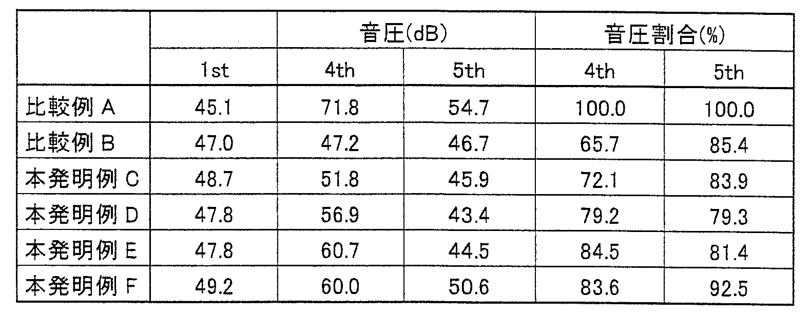
本発明例Cは、本発明例Dより4次の振動モードの音圧が小さくなっている。これより、4次の振動モードの腹部にバッジ部20を貼り付けることで、4次の振動モードの音圧を特に下げることができることを確認した。また、本発明例E、Fは、本発明例Cより音圧が大きくなった。本発明例C、E、Fでは、比較例Aの4次の振動モードの音圧と比較したそれぞれの音圧割合(%)は72.1%以上84.5%以下となった。
また、本発明例Dは、比較例Aより5次の振動モード(5th)の音圧が小さくなっている。また本発明例Dは、本発明例C、E、Fより5次の振動モードの音圧が小さくなっている。これより、5次の振動モードの腹部にバッジ部20を貼り付けることで、5次の振動モードの音圧を特に下げることができることを確認した。本発明例Dでは、比較例Aの5次の振動モードの音圧と比較した音圧割合(%)は、79.3%となった。
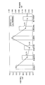
図7および表2を参照して、本発明例C~Fは、比較例Bより響き時間(秒)が長くなっている。

これより、本発明例C~Fは響き時間の低下を抑制できることを確認した。本発明例C~Fでは、比較例Aの響き時間と比較したそれぞれの響き時間割合(%)は49.0%以上71.3%以下となった。また、本発明例E、Fは、本発明例Cより響き時間が長くなっている。これより、バッジ部20が貼り付けられたバック面13の面積A2を小さくすることで響き時間を長くすることができることを確認した。
以上より、響き時間の低下を抑制するとともに4次または5次少なくともいずれかの振動モードの音圧を下げることができることを確認した。
また、図7および表2を参照して、バッジ部20が貼り付けられたバック面13の面積A2が800cm2で響き時間の減少する割合が低下することが分かった。
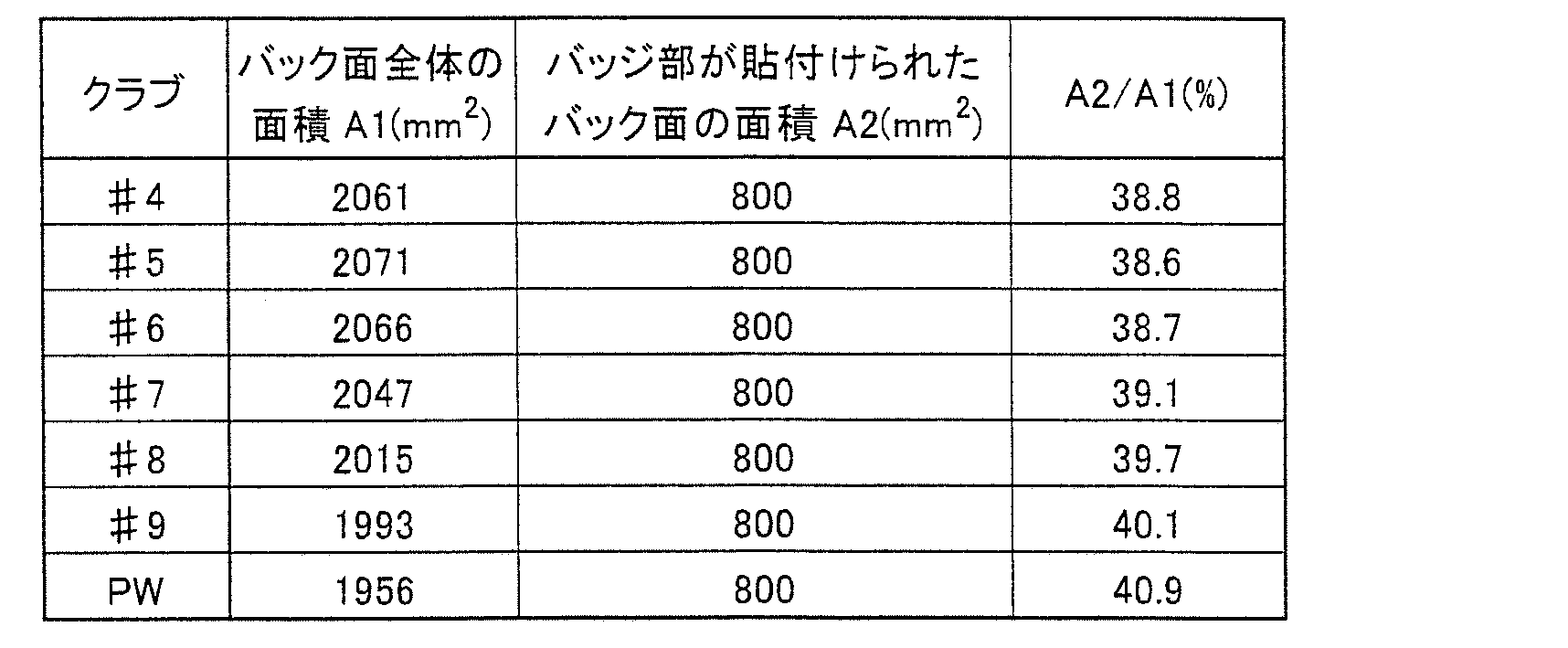
表3を参照して、4番アイアンゴルフクラブ(♯4)~9番アイアンゴルフクラブ(♯9)およびピッチングウェッジ(PW)について、バッジ部20が貼り付けられたバック面13の面積A2が800mm2となるようにバッジ部20を貼り付けた。バック面13全体の面積A1(mm2)に対するバッジ部20が貼り付けられたバック面13の面積A2(mm2)の割合(A2/A1)は、38.6%以上40.9%以下となった。
続いて、4次および5次の振動モードにおける音圧および響き時間の変化についてさらに説明する。
以下の本発明例1~4の値は3回測定した値の平均値である。本発明例1および2は、4次の振動モードの腹部にバッジ部20が両面テープで貼り付けられている。本発明例1では両面テープの厚さが0.4mmである。本発明例2では両面テープの厚さが0.8mmである。
本発明例3および4は、5次の振動モードの腹部にバッジ部20が両面テープで貼り付けられている。本発明例1では両面テープの厚さが0.4mmである。本発明例2では両面テープの厚さが0.8mmである。
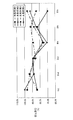
図8および表4を参照して、本発明例1~4の1次~6次の固有値における振動モードの音圧は、バッジ部20が貼り付けられていない場合の音圧と比較して低下している。
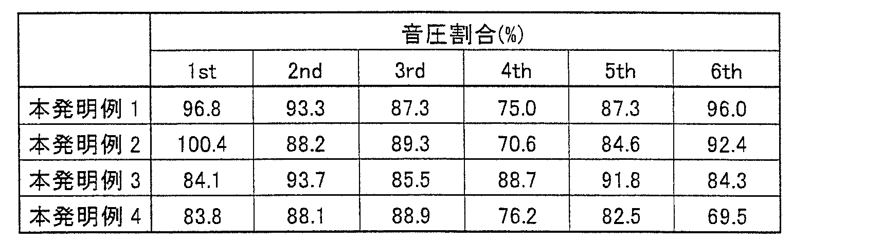
4次の振動モード(4th)では、本発明例1および本発明例2の音圧が特に低下している。これより、4次の振動モードの腹部にバッジ部20を貼り付けることで、4次の振動モードの音圧を特に下げることができることを確認した。
バッジ部20が貼り付けられていない場合の音圧と比較して、4次の振動モードでは、本発明例1の音圧割合(%)は75.0%であり、本発明例2の音圧割合(%)は70.6%である。両面テープの厚さが厚い本発明例2の方が本発明例1より音圧が低下することがわかった。
5次の振動モード(5th)では、本発明例3および本発明例4の音圧が低下している。これより、5次の振動モードの腹部にバッジ部20を貼り付けることで、5次の振動モードの音圧を特に下げることができることを確認した。
バッジ部20が貼り付けられていない場合の音圧と比較して、5次の振動モードでは、本発明例4は82.5%である。両面テープの厚さが厚い本発明例2の方が本発明例1より音圧が低下することがわかった。
上記より、4次および5次の振動モードの腹部にバッジ部20を貼り付けることで、4次および5次の少なくともいずれかの振動モードの音圧を特に下げることができることをさらに詳しく確認した。
図9および表5を参照して、本発明例1~4および比較例1~2について、4次および5次の振動モードにおけるA補正音圧(A-Weight)と響き時間とを説明する。

比較例1は4次の振動モードでの比較例であり、バッジ部20が貼り付けられていない。本発明例1および本発明例2のバッジ部20が貼り付けられたバック面13の面積A2は553mm2である。本発明例1および本発明例2のA補正音圧(A-wt)は、比較例1のA補正音圧より低下した。A補正音圧について、本発明例1は68.5(dB)であり、本発明例2は67.0(dB)である。
また響き時間については、本発明例1は0.575秒であって比較例1の63.1%であり、本発明例2は0.497秒であって比較例1の54.6%である。
比較例2は5次の振動モードの比較例であり、バッジ部20が貼り付けられていない。本発明例3および4のバッジ部20が貼り付けられた面積A2は820mm2である。本発明例3および4のA補正音圧は、比較例2のA補正音圧より低下した。A補正音圧について、本発明例3は70.1(dB)であり、本発明例4は67.6(dB)である。
また響き時間については、本発明例3は0.609秒であって比較例2の59.3%であり、本発明例4は0.553秒であって比較例2の53.8%である。
4次の振動モードの響き音の減少率と5次の振動モードの響き音の減少率はほぼ同等となることがわかった。4次の振動モードおよび5次の振動モードの両方で両面テープが厚い方がA補正音圧および響き時間が低下することが分かった。
本願発明者等は、上記の効果を確認すべく、4次および5次の振動モードの腹部にバッジ部20を貼り付けた2種類のアイアンゴルフクラブ50を作製し、それぞれについて4名の女子プロゴルファによる試打試験を行った。試打試験を行ったすべての女子プロゴルファが上記2種類のアイアンゴルフクラブ50の打感が良好であると判定した。このことからも、4次および5次の少なくともいずれかの振動モードの腹部にバッジ部20を貼り付けることにより、打感を向上できることがわかった。
今回開示された実施の形態および実施例はすべての点で例示であって制限的なものではないと考えられるべきである。本発明の範囲は上記した説明ではなくて請求の範囲によって示され、請求の範囲と均等の意味および範囲内でのすべての変更が含まれることを意図される。
本発明は、ヘッド部にバッジ部が貼り付けられたアイアンゴルフクラブヘッドおよびアイアンゴルフクラブに特に有利に適用され得る。
10 ヘッド部、11 フェース面、12 溝部、13 バック面、14 キャビティ立ち面、15 打点、20 バッジ部、21 第1最大振幅領域、22 第1小振幅領域、23 第2最大振幅領域、24 第2小振幅領域、30 アイアンゴルフクラブヘッド、50 アイアンゴルフクラブ、51 シャフト、52 グリップ、A1 バック面全体の面積、A2 バッジ部が貼り付けられたバック面の面積。
Claims (5)
- ヘッド部(10)と、
前記ヘッド部(10)に貼り付けられたバッジ部(20)とを備え、
前記ヘッド部(10)は、
フェース面(11)と、
前記フェース面(11)の後方に位置するバック面(13)とを含み、
前記バック面(13)の4次の振動モードにおける振幅が最も大きい第1最大振幅領域(21)および5次の振動モードにおける振幅が最も大きい第2最大振幅領域(23)の少なくとも一方に前記バッジ部(20)が貼り付けられている、アイアンゴルフクラブヘッド(30)。 - 前記第1最大振幅領域(21)を規定するようにその周囲に配置され、4次の振動モードにおける振幅が前記第1最大振幅領域(21)よりも小さい第1小振幅領域(22)と、
前記第2最大振幅領域(23)を規定するようにその周囲に配置され、5次の振動モードにおける振幅が前記第2最大振幅領域(23)よりも小さい第2小振幅領域(24)とをさらに備え、
前記第1小振幅領域(22)および前記第2小振幅領域(24)の少なくとも一方と重ならないように前記バッジ部(20)が貼り付けられている、請求項1に記載のアイアンゴルフクラブヘッド(30)。 - 前記バッジ部(20)が貼り付けられた前記バック面(13)の面積は、前記バック面(13)全体の面積の38.6%以上40.9%以下である、請求項1に記載のアイアンゴルフクラブヘッド(30)。
- 前記ヘッド部(10)の反発係数は0.8以上である、請求項1に記載のアイアンゴルフクラブヘッド(30)。
- シャフト(51)と、
前記シャフト(51)の一方端に取り付けられたグリップ(52)と、
前記シャフト(51)の前記グリップ(52)と反対側の他方端に取り付けられた請求項1に記載のアイアンゴルフクラブヘッド(30)とを備えた、アイアンゴルフクラブ(50)。
Priority Applications (2)
| Application Number | Priority Date | Filing Date | Title |
|---|---|---|---|
| EP12763316.2A EP2548622B1 (en) | 2011-03-31 | 2012-03-26 | Iron golf club head and iron golf club |
| JP2012532394A JP5095044B1 (ja) | 2011-03-31 | 2012-03-26 | アイアンゴルフクラブヘッドおよびアイアンゴルフクラブ |
Applications Claiming Priority (2)
| Application Number | Priority Date | Filing Date | Title |
|---|---|---|---|
| JP2011-079660 | 2011-03-31 | ||
| JP2011079660 | 2011-03-31 |
Publications (1)
| Publication Number | Publication Date |
|---|---|
| WO2012133310A1 true WO2012133310A1 (ja) | 2012-10-04 |
Family
ID=46927964
Family Applications (1)
| Application Number | Title | Priority Date | Filing Date |
|---|---|---|---|
| PCT/JP2012/057756 Ceased WO2012133310A1 (ja) | 2011-03-31 | 2012-03-26 | アイアンゴルフクラブヘッドおよびアイアンゴルフクラブ |
Country Status (4)
| Country | Link |
|---|---|
| US (1) | US8834292B2 (ja) |
| EP (1) | EP2548622B1 (ja) |
| JP (1) | JP5095044B1 (ja) |
| WO (1) | WO2012133310A1 (ja) |
Cited By (1)
| Publication number | Priority date | Publication date | Assignee | Title |
|---|---|---|---|---|
| JP2019176972A (ja) * | 2018-03-30 | 2019-10-17 | 美津濃株式会社 | アイアンゴルフクラブヘッド |
Families Citing this family (9)
| Publication number | Priority date | Publication date | Assignee | Title |
|---|---|---|---|---|
| AU2014362231B2 (en) | 2013-12-11 | 2019-04-04 | Biogen Ma Inc. | Biaryl compounds useful for the treatment of human diseases in oncology, neurology and immunology |
| US10071291B2 (en) | 2015-05-11 | 2018-09-11 | Karsten Manufacturing Corporation | Golf irons with sealed undercut |
| US10335651B2 (en) | 2015-05-28 | 2019-07-02 | Karsten Manufacturing Corporation | Iron-type golf club heads with a dual-density insert |
| JP6120906B2 (ja) * | 2015-06-08 | 2017-04-26 | 美津濃株式会社 | ゴルフクラブヘッドおよびゴルフクラブ |
| US20180339207A1 (en) * | 2016-07-26 | 2018-11-29 | Acushnet Company | Golf club set having an elastomer element for ball speed control |
| US11938387B2 (en) * | 2016-07-26 | 2024-03-26 | Acushnet Company | Golf club having a damping element for ball speed control |
| US10828538B2 (en) | 2018-05-04 | 2020-11-10 | Parsons Xtreme Golf, LLC | Golf club heads and methods to manufacture golf club heads |
| JP7618798B2 (ja) | 2020-10-30 | 2025-01-21 | カーステン マニュファクチュアリング コーポレーション | アンダーカットおよびインサート付きゴルフクラブヘッド |
| JP7669711B2 (ja) * | 2021-02-05 | 2025-04-30 | 住友ゴム工業株式会社 | ゴルフクラブヘッド |
Citations (3)
| Publication number | Priority date | Publication date | Assignee | Title |
|---|---|---|---|---|
| JPH11347161A (ja) * | 1998-06-05 | 1999-12-21 | Bridgestone Sports Co Ltd | アイアンゴルフクラブヘッド |
| JP2010148565A (ja) | 2008-12-24 | 2010-07-08 | Sri Sports Ltd | ゴルフクラブヘッド |
| JP2011030837A (ja) * | 2009-08-03 | 2011-02-17 | Bridgestone Sports Co Ltd | ゴルフクラブヘッド |
Family Cites Families (11)
| Publication number | Priority date | Publication date | Assignee | Title |
|---|---|---|---|---|
| FR2689771B1 (fr) * | 1992-04-14 | 1994-06-03 | Rossignol Sa | Tete de club de golf. |
| US5409229A (en) * | 1992-08-05 | 1995-04-25 | Callaway Golf Company | Golf club head with audible vibration attenuation |
| US5830084A (en) * | 1996-10-23 | 1998-11-03 | Callaway Golf Company | Contoured golf club face |
| US6042486A (en) * | 1997-11-04 | 2000-03-28 | Gallagher; Kenny A. | Golf club head with damping slot and opening to a central cavity behind a floating club face |
| US7476162B2 (en) * | 2003-09-19 | 2009-01-13 | Nike, Inc. | Golf club head having a bridge member and a damping element |
| US20060258480A1 (en) * | 2005-05-10 | 2006-11-16 | Nelson Precision Casting Co., Ltd. | Golf club head with elastic weight members |
| JP5189827B2 (ja) * | 2007-11-07 | 2013-04-24 | ダンロップスポーツ株式会社 | ゴルフクラブヘッド |
| JP5161546B2 (ja) * | 2007-11-26 | 2013-03-13 | ダンロップスポーツ株式会社 | ゴルフクラブヘッド |
| US8333667B2 (en) * | 2008-12-03 | 2012-12-18 | Sri Sports Limited | Golf club head |
| JP5351646B2 (ja) * | 2009-07-29 | 2013-11-27 | ダンロップスポーツ株式会社 | ゴルフクラブヘッド |
| CN102794003A (zh) * | 2011-05-23 | 2012-11-28 | 普利司通运动株式会社 | 高尔夫球杆头 |
-
2012
- 2012-03-26 WO PCT/JP2012/057756 patent/WO2012133310A1/ja not_active Ceased
- 2012-03-26 EP EP12763316.2A patent/EP2548622B1/en not_active Not-in-force
- 2012-03-26 JP JP2012532394A patent/JP5095044B1/ja active Active
- 2012-03-28 US US13/432,115 patent/US8834292B2/en not_active Expired - Fee Related
Patent Citations (3)
| Publication number | Priority date | Publication date | Assignee | Title |
|---|---|---|---|---|
| JPH11347161A (ja) * | 1998-06-05 | 1999-12-21 | Bridgestone Sports Co Ltd | アイアンゴルフクラブヘッド |
| JP2010148565A (ja) | 2008-12-24 | 2010-07-08 | Sri Sports Ltd | ゴルフクラブヘッド |
| JP2011030837A (ja) * | 2009-08-03 | 2011-02-17 | Bridgestone Sports Co Ltd | ゴルフクラブヘッド |
Non-Patent Citations (1)
| Title |
|---|
| See also references of EP2548622A4 |
Cited By (2)
| Publication number | Priority date | Publication date | Assignee | Title |
|---|---|---|---|---|
| JP2019176972A (ja) * | 2018-03-30 | 2019-10-17 | 美津濃株式会社 | アイアンゴルフクラブヘッド |
| US10716979B2 (en) | 2018-03-30 | 2020-07-21 | Mizuno Corporation | Iron golf club head |
Also Published As
| Publication number | Publication date |
|---|---|
| EP2548622B1 (en) | 2015-06-17 |
| EP2548622A4 (en) | 2014-04-02 |
| EP2548622A1 (en) | 2013-01-23 |
| US8834292B2 (en) | 2014-09-16 |
| JPWO2012133310A1 (ja) | 2014-07-28 |
| JP5095044B1 (ja) | 2012-12-12 |
| US20120252600A1 (en) | 2012-10-04 |
Similar Documents
| Publication | Publication Date | Title |
|---|---|---|
| JP5095044B1 (ja) | アイアンゴルフクラブヘッドおよびアイアンゴルフクラブ | |
| US9168430B2 (en) | Golf club head | |
| US7018305B2 (en) | Iron-type golf club head | |
| JP2024026315A (ja) | フェースプレートの変形を制限するためのサポートを有するゴルフクラブヘッド | |
| JP4769210B2 (ja) | ゴルフクラブヘッド | |
| US9586105B1 (en) | Weighted golf club head | |
| US20060116219A1 (en) | Iron-type golf club head | |
| WO2013158146A1 (en) | Weighted golf club head | |
| JP2014111170A (ja) | 交換可能なヘッドを具備するゴルフクラブヘッド | |
| US7022031B2 (en) | Iron-type golf club head | |
| JP2004049733A (ja) | ゴルフクラブヘッド | |
| JP5824593B1 (ja) | アイアン型ゴルフクラブヘッド | |
| JP5548281B2 (ja) | アイアン型ゴルフクラブヘッド | |
| JP5217181B2 (ja) | ゴルフクラブヘッドおよびゴルフクラブ | |
| JP4044382B2 (ja) | ゴルフクラブヘッド | |
| JP2004135858A (ja) | ウッド型金属製中空ゴルフクラブヘッドおよびゴルフクラブ | |
| JP5784949B2 (ja) | アイアンゴルフクラブヘッドおよびアイアンゴルフクラブ | |
| JP5708870B1 (ja) | ゴルフクラブヘッド | |
| JP4256248B2 (ja) | アイアン型ゴルフクラブヘッド | |
| US11666805B2 (en) | Golf club head | |
| JP2004008409A (ja) | ゴルフクラブヘッド | |
| JP4283394B2 (ja) | アイアンクラブ | |
| JP3208316U (ja) | ゴルフクラブヘッド | |
| JP2013013501A (ja) | ゴルフクラブヘッド | |
| US10272305B2 (en) | Golf club set |
Legal Events
| Date | Code | Title | Description |
|---|---|---|---|
| ENP | Entry into the national phase |
Ref document number: 2012532394 Country of ref document: JP Kind code of ref document: A |
|
| WWE | Wipo information: entry into national phase |
Ref document number: 2012763316 Country of ref document: EP |
|
| 121 | Ep: the epo has been informed by wipo that ep was designated in this application |
Ref document number: 12763316 Country of ref document: EP Kind code of ref document: A1 |
|
| NENP | Non-entry into the national phase |
Ref country code: DE |