WO2012133460A1 - Connecteur de blindage - Google Patents
Connecteur de blindage Download PDFInfo
- Publication number
- WO2012133460A1 WO2012133460A1 PCT/JP2012/058012 JP2012058012W WO2012133460A1 WO 2012133460 A1 WO2012133460 A1 WO 2012133460A1 JP 2012058012 W JP2012058012 W JP 2012058012W WO 2012133460 A1 WO2012133460 A1 WO 2012133460A1
- Authority
- WO
- WIPO (PCT)
- Prior art keywords
- shield
- connector
- cable
- shield case
- shell
- Prior art date
- Legal status (The legal status is an assumption and is not a legal conclusion. Google has not performed a legal analysis and makes no representation as to the accuracy of the status listed.)
- Ceased
Links
Images


Classifications
-
- H—ELECTRICITY
- H01—ELECTRIC ELEMENTS
- H01R—ELECTRICALLY-CONDUCTIVE CONNECTIONS; STRUCTURAL ASSOCIATIONS OF A PLURALITY OF MUTUALLY-INSULATED ELECTRICAL CONNECTING ELEMENTS; COUPLING DEVICES; CURRENT COLLECTORS
- H01R13/00—Details of coupling devices of the kinds covered by groups H01R12/70 or H01R24/00 - H01R33/00
- H01R13/648—Protective earth or shield arrangements on coupling devices, e.g. anti-static shielding
- H01R13/658—High frequency shielding arrangements, e.g. against EMI [Electro-Magnetic Interference] or EMP [Electro-Magnetic Pulse]
- H01R13/6591—Specific features or arrangements of connection of shield to conductive members
-
- H—ELECTRICITY
- H01—ELECTRIC ELEMENTS
- H01R—ELECTRICALLY-CONDUCTIVE CONNECTIONS; STRUCTURAL ASSOCIATIONS OF A PLURALITY OF MUTUALLY-INSULATED ELECTRICAL CONNECTING ELEMENTS; COUPLING DEVICES; CURRENT COLLECTORS
- H01R13/00—Details of coupling devices of the kinds covered by groups H01R12/70 or H01R24/00 - H01R33/00
- H01R13/648—Protective earth or shield arrangements on coupling devices, e.g. anti-static shielding
- H01R13/658—High frequency shielding arrangements, e.g. against EMI [Electro-Magnetic Interference] or EMP [Electro-Magnetic Pulse]
- H01R13/6581—Shield structure
-
- H—ELECTRICITY
- H01—ELECTRIC ELEMENTS
- H01R—ELECTRICALLY-CONDUCTIVE CONNECTIONS; STRUCTURAL ASSOCIATIONS OF A PLURALITY OF MUTUALLY-INSULATED ELECTRICAL CONNECTING ELEMENTS; COUPLING DEVICES; CURRENT COLLECTORS
- H01R13/00—Details of coupling devices of the kinds covered by groups H01R12/70 or H01R24/00 - H01R33/00
- H01R13/73—Means for mounting coupling parts to apparatus or structures, e.g. to a wall
- H01R13/74—Means for mounting coupling parts in openings of a panel
- H01R13/748—Means for mounting coupling parts in openings of a panel using one or more screws
-
- H—ELECTRICITY
- H01—ELECTRIC ELEMENTS
- H01R—ELECTRICALLY-CONDUCTIVE CONNECTIONS; STRUCTURAL ASSOCIATIONS OF A PLURALITY OF MUTUALLY-INSULATED ELECTRICAL CONNECTING ELEMENTS; COUPLING DEVICES; CURRENT COLLECTORS
- H01R2201/00—Connectors or connections adapted for particular applications
- H01R2201/26—Connectors or connections adapted for particular applications for vehicles
Definitions
- the present invention relates to a shield connector for connecting an external cable to a circuit in a shield case of a device.
- FIG. 8 shows a conventional example of a shield connector.
- the shield connector 100 is disclosed in Patent Document 1 below.
- the shield connector 100 is a connector for connecting the external cable 110 to a circuit in a shield case 103 of a device mounted on a vehicle or the like.
- the shield connector 100 includes a cable-side connection terminal 120 that is crimped to the tip of an external cable 110, a resin housing 130 that accommodates and holds the cable-side connection terminal 120, and a shield case 103 that holds the resin housing 130. And a seal shell 140 that is screwed to each other and a packing 150 that seals between the shield connector 100 and the shield case 103.
- the cable side connection terminal 120 includes a tongue-shaped terminal portion 121 at one end and a wire crimping portion 122 at the other end.
- the tongue-shaped terminal portion 121 is a portion connected to the tongue-shaped terminal 104 of the circuit in the shield case 103 via screw members 105 and 106.
- the wire crimping part 122 is a part that is crimped to the end of the external cable 110.
- the resin housing 130 is integrally formed in a form in which the cable side connection terminal 120 is accommodated by molding.
- the outer shape of the resin housing 130 is a columnar shape that can be inserted into the connector insertion hole 107 formed through the shield case 103.
- a packing mounting groove 131 for mounting the packing 150 is formed in an annular shape that goes around the outer periphery.
- the shield shell 140 extends in a bowl shape from the cylindrical shell main body 141 that holds the base end portion 130 a of the resin housing 130 that houses the end of the external cable 110, and the end of the shell main body 141 on the shield case 103 side. And a case fixing flange portion 142 provided.
- the case fixing flange 142 is brought into face contact with the outer surface of the shield case 103 and is screwed to the shield case 103 with a bolt 108.
- the shield connector 100 is fixed to the shield case 103 by screwing the case fixing flange portion 142 to the shield case 103.
- the packing 150 is a ring-shaped packing that is mounted in the packing mounting groove 131 of the resin housing 130.
- the packing 150 closes a gap between the inner peripheral surface of the connector insertion hole 107 and the outer peripheral surface of the resin housing 130 and seals between the shield connector 100 and the shield case 103.
- the ring-shaped packing 150 provided on the outer periphery of the resin housing 130 that is inserted through the connector insertion hole 107 is brought into close contact with the inner peripheral surface of the connector insertion hole 107.
- the shield connector 100 and the shield case 103 are sealed. Therefore, when the external cable 110 is repeatedly attached to and detached from the shield case 103, the packing 150 is easily damaged by sliding with the connector insertion hole 107, and the sealing performance at the attachment portion to the shield case 103 may be deteriorated.
- the mounting dimensions on the shield case 103 such as a change in the arrangement of the screw holes 109 on the shield case 103 to which the bolts 108 are screwed or a change in the shape or dimensions of the connector insertion hole 107 are changed.
- the change is supported.
- the mounting dimensions on the shield case 103 side are changed, it is necessary to change the design of a large number of components, and there is a problem that a great deal of labor is required for product development corresponding to the change in the mounting dimensions on the shield case side. there were.
- an object of the present invention is to solve the above-mentioned problems, and even if the external cable is repeatedly attached to and detached from the shield case, the sealing performance at the attachment portion to the shield case does not deteriorate, and the shield It is an object of the present invention to provide a shielded connector that can facilitate product development corresponding to a change in mounting dimensions on the case side.
- a shield connector for connecting an external cable to a circuit in a shield case of a device A device-side connector that is fixed to the shield case, and a cable-side connector that is attached to an end of the external cable and is connected to the device-side connector;
- the device-side connector is One end is connected to the circuit in the shield case and the other end is fitted and connected to the connection terminal on the cable side connector side, Housing and holding the device-side connection terminal and fitting and connecting the cable-side connector, and a device-side resin housing;
- the device side shield shell having a case fixing flange portion that holds the device side resin housing and is screwed to the outer surface of the shield case in a surface contact state;
- a first packing that is pressed against the outer surface of the shield case by screwing the case fixing flange portion to the shield case and seals between the device-side connector and the shield case;
- the device-side shield shell includes a mating shell fixing portion that couples the device-side shield shell and the cable-side
- the device-side shield shell is formed in a thick wall shape projecting outward of the shield case from the projecting height of a screw member that fastens the case fixing flange portion to the shield case.
- a thick part that functions as a hood part that accommodates the fitting part of the cable side connector is provided,
- the shield connector is composed of a device-side connector fixed to the shield case, and a cable-side connector that is attached to the end of the external cable and is fitted and connected to the device-side connector. ing. Therefore, attachment / detachment of the external cable to / from the shield case is realized by attaching / detaching the cable-side connector to / from the device-side connector.
- the device-side connector when the external cable is attached to or detached from the shield case, the device-side connector may remain fixed to the shield case, and even if the external cable is repeatedly attached to and detached from the shield case, the device-side connector may remain between the device-side connector and the shield case.
- the first packing that seals is not affected at all.
- the sealing between the shield case and the device side connector is performed by a first packing sandwiched between the case fixing flange portion of the shield shell and the outer surface of the shield case, and the device side resin housing Need only be loosely fitted into the connector insertion hole on the shield case, and the dimensional accuracy of the outer shape of the device-side resin housing does not affect the sealing performance at the attachment portion to the shield case.
- the change can be dealt with by changing the design of only the shield shell that is attached to the shield case.
- the mating dimensions of can be kept as they were in the past.
- the device-side resin housing since the thick portion provided in the shield shell also serves as the hood portion that houses the tip portion of the cable-side connector, the device-side resin housing has the tip portion of the cable-side connector. It is not necessary to form a hood to be accommodated, and the structure of the device-side resin housing can be simplified.
- the mating shell fixing part is equipped in the thick part, it is possible to secure a sufficient length in the screw hole as the mating shell fixing part and to improve the coupling strength by screwing.
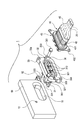
- FIG. 1 is an exploded perspective view of an embodiment of a shield connector according to the present invention.
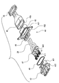
- 2 is an exploded perspective view of the device-side connector shown in FIG.
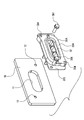
- FIG. 3 is an exploded perspective view of the cable side connector shown in FIG.
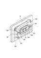
- FIG. 4 is a perspective view of another embodiment of the device-side connector according to the present invention.
- FIG. 5 is a perspective view of a state in which the device-side connector shown in FIG. 4 is fixed to a shield case.
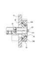
- FIG. 6 is a perspective view, partly in section, of the device-side connector and shield case shown in FIG. 7 is a longitudinal sectional view of the device-side connector and the shield case shown in FIG.
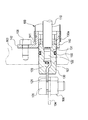
- FIG. 8 is a longitudinal sectional view of a conventional shield connector.
- the shield connector 1 of the present embodiment is a connector for connecting an external cable 20 to a circuit in a shield case 10 of a device mounted on a vehicle or the like.
- the shield connector 1 of the present embodiment includes a device-side connector 30 that is fixed to the shield case 10 and a cable-side connector 40 that is attached to the end of the external cable 20 and is fitted and connected to the device-side connector 30. Yes.
- the shield case 10 is provided with a connector insertion hole 11 and a screw hole 12 for fixing the connector in order to attach the device-side connector 30.
- the connector insertion hole 11 is an opening through which a device-side resin housing 32 of a device-side connector 30 described later is inserted.
- the screw hole 12 is a screw hole into which a bolt 361 for fastening a device-side shield shell 33 of the device-side connector 30 described later is screwed.
- the screw holes 12 are provided at two locations located on the diagonal of the outer periphery of the connector insertion hole 11.
- the external cable 20 is an electric wire that supplies power to a device (not shown) mounted on a vehicle or the like and transmits / receives a signal.
- the external cable 20 connected to the cable-side connector 40 is covered with a tubular braid 45 that electromagnetically shields the periphery of the external cable 20.
- the device-side connector 30 includes a device-side connection terminal 31, a device-side resin housing 32, a device-side shield shell 33, a first packing 34, a second packing 35, and a terminal. Sealing ring 36.
- the device-side connection terminal 31 is made of a metal plate and includes a circuit connection portion 311 at one end and a tongue-like terminal portion 312 at the other end.
- the circuit connection portion 311 is conductively connected to a terminal (not shown) of a circuit in the device by screwing.
- the tongue-like terminal portion 312 is a part that is fitted and connected to the connection terminal on the cable side connector 40 side.
- the device-side resin housing 32 includes a terminal housing cylinder portion 321 that accommodates and holds the device-side connection terminal 31 and a housing flange portion 322 that is formed in a bowl shape on the outer periphery of the terminal accommodation cylinder portion 321.
- the terminal accommodating cylinder portion 321 is set to have an outer shape smaller than the connector insertion hole 11 so as to loosely fit into the connector insertion hole 11.
- the housing flange 322 is set to have an outer shape larger than that of the connector insertion hole 11 so as not to be inserted through the connector insertion hole 11.
- the device-side resin housing 32 has a locking piece 323 for coupling with a device-side shield shell 33 described later. In the state where the device-side resin housing 32 is coupled to the device-side shield shell 33, a later-described cable-side connector 40 can be fitted and connected.
- the device-side shield shell 33 is made of a conductive material and has a locking portion 331 that locks the locking piece 323 of the device-side resin housing 32.
- the device-side shield shell 33 holds the device-side resin housing 32 by electromagnetically shielding the periphery of the device-side resin housing 32 by locking the locking pieces 323 with the locking portions 331.
- the device-side shield shell 33 further includes a case fixing flange portion 333 that is screwed to the outer surface of the shield case 10 in a surface contact state, and a mating shell fixing portion 334. As shown in FIG. 1, the case fixing flange portion 333 is screwed to the shield case 10 by a bolt 361 that is a screw member screwed into the screw hole 12.
- the mating shell fixing part 334 is a screw hole for screwing the cable side connector 40.
- the mating shell fixing portion 334 fastens a later-described cable-side shield shell 43 (see FIG. 3) provided in the cable-side connector 40 in a fitting connection state between the device-side connector 30 and the cable-side connector 40.
- the device-side shield shell 33 and the cable-side shield shell 43 are coupled in a conductive state.
- the mating shell fixing portion 334 is provided in the thick portion 336 located inside the case fixing flange portion 333.
- the thick portion 336 is a thick wall that protrudes outward of the shield case 10 from the protruding height (below neck length) of the bolt 361 that is a screw member for fastening the case fixing flange portion 333 to the shield case 10. It is formed in a shape.
- the thick portion 336 has a fitting portion receiving hole 337 formed through the central portion.
- the fitting portion accommodating hole 337 is a hole for accommodating a terminal accommodating cylinder portion 421 of a cable side resin housing 42 described later in the cable side connector 40. Since the fitting portion accommodation hole 337 is provided, the thick portion 336 functions as a hood portion that accommodates the fitting portion of the cable-side connector 40.
- the mating shell fixing part 334 is equipped on the thick part 336.
- the depth of the screw hole as the mating shell fixing part 334 is set so as not to penetrate the thick part 336.
- the first packing 34 is attached to the rear surface of the outer peripheral edge of the housing flange 322 of the device-side resin housing 32 so as to face the outer surface of the shield case 10.
- the first packing 34 is pressed against the outer surface of the shield case 10 (periphery of the connector insertion hole 11) by screwing the case fixing flange 333 of the device side shield shell 33 to the shield case 10, The space between the side connector 30 and the shield case 10 is sealed.
- the second packing 35 is fitted to the outer periphery of the housing flange 322 of the device-side resin housing 32 so as to face the device-side shield shell 33 by being fitted to the outer periphery of the terminal housing cylinder portion 321. It is done.
- the second packing 35 is sandwiched between the housing flange 322 of the device-side resin housing 32 and the device-side shield shell 33, and seals between the device-side resin housing 32 and the device-side shield shell 33. .
- the terminal seal ring 36 is fitted into the tongue-shaped terminal portion 312 of the device-side connection terminal 31 held by the terminal accommodating cylinder portion 321, and moisture enters the shield case 10 through the tongue-shaped terminal portion 312. To prevent.
- the cable side connector 40 accommodates and holds a cable side connection terminal 41, a cable side resin housing 42 for accommodating and holding the cable side connection terminal 41, and the cable side resin housing 42.
- a cable-side shield shell 43 that can be screwed to the device-side shield shell 33 of the device-side connector 30, a tubular braid 45 that covers the external cable 20 connected to the cable-side connection terminal 41, and a tubular braid 45.
- a braided fixing ring 46 for fixing to the cable-side shield shell 43, a rubber plug 47 attached to the external cable 20 connected to the cable-side connection terminal 41, and attached to the external cable 20 after the rubber plug 47.
- An electric wire holder 48 and a third packing 49 are provided.
- the cable side connection terminal 41 is provided with a terminal fitting portion 411 that is fitted to the tongue-like terminal portion 312 of the device side connection terminal 31 at one end and a wire crimping portion 412 to which the external cable 20 is crimped and connected at the other end. It has been.
- the cable-side resin housing 42 includes a terminal housing cylinder portion 421 that accommodates the cable-side connection terminal 41 and a housing flange portion 422 that is formed in a bowl shape on the outer periphery of the terminal accommodation cylinder portion 421.
- the cable side shield shell 43 includes a cylindrical portion 431 that accommodates the rear end portion of the terminal accommodating cylinder portion 421 and a connector coupling flange portion 432 that is formed in a hook shape at the front end of the cylindrical portion 431.
- the connector coupling flange portion 432 is abutted against the thick portion 336 of the device-side shield shell 33 and is screwed to the mating shell fixing portion 334.
- the cable side connector 40 is coupled to the device side connector 30 by screwing the connector coupling flange portion 432 to the mating shell fixing portion 334.
- the tubular braid 45 covers the outer periphery of the external cable 20 extending behind the cable-side shield shell 43 and electromagnetically shields the periphery of the external cable 20.
- the front end 45 a of the braid 45 has a cylindrical shape that is fitted around the cylindrical portion 431 of the cable-side shield shell 43.
- the braid fixing ring 46 connects the tubular braid 45 to the cable-side shield shell 43 by fastening the tubular braid 45 fitted around the tubular portion 431 of the cable-side shield shell 43 to the tubular portion 431.
- the rubber plug 47 When the cable-side connection terminal 41 is inserted into the terminal accommodation hole formed in the terminal accommodation cylinder portion 421, the rubber plug 47 is tightly fitted into the terminal accommodation hole and passes through the external cable 20 to the terminal accommodation hole side. Prevent water from entering.
- the electric wire holder 48 is held in the cylindrical portion 431 while being fitted to the external cable 20, and restricts the displacement of the external cable 20 in the cylindrical portion 431.
- the third packing 49 is sandwiched between the housing flange portion 422 of the cable-side resin housing 42 and the connector coupling flange portion 432 of the cable-side shield shell 43, so that the cable-side resin housing 42 and the cable-side shield shell are disposed. 43 is sealed.
- the shield connector 1 is attached to the device-side connector 30 fixed to the shield case 10 and the end of the external cable 20 and is fitted and connected to the device-side connector 30. Cable side connector 40. Therefore, attachment / detachment of the external cable 20 to / from the shield case 10 is realized by attaching / detaching the cable-side connector 40 to / from the device-side connector 30.
- the equipment-side connector 30 may remain fixed to the shield case 10, and the equipment-side connector can be used even when the external cable 20 is repeatedly attached to and detached from the shield case 10.
- the first packing 34 that seals between the shield 30 and the shield case 10 is not affected at all.
- the sealing between the shield case 10 and the device-side connector 30 is performed between the case fixing flange portion 333 of the device-side shield shell 33 and the outer surface of the shield case 10.
- the device-side resin housing 32 only needs to be loosely fitted in the connector insertion hole 11 on the shield case 10, and the external dimensions of the device-side resin housing 32 are as follows. The accuracy does not affect the sealing performance at the attachment portion to the shield case 10.
- the change can be dealt with by changing the design of only the device-side shield shell 33 that is attached to the shield case 10, and the device-side resin is used.
- the mating dimension between the housing 32 and the shield shell can be kept as is.
- the design change of the component parts corresponding to the change is small, and the product development corresponding to the change of the mounting dimension on the shield case 10 side can be facilitated. it can.
- the thick portion 336 provided in the device-side shield shell 33 also serves as a hood portion that houses the distal end portion of the cable-side connector 40. 32 does not require the formation of a hood portion that accommodates the distal end portion of the cable-side connector 40, and the structure of the device-side resin housing 32 can be simplified.
- the mating shell fixing portion 334 is provided in the thick wall portion 336, a sufficient length (depth) is secured in the screw hole as the mating shell fixing portion 334, and the device side connector 30 and the cable by screwing are secured.
- the coupling strength with the side connector 40 can be improved.
- FIG. 4 is a perspective view of another embodiment of the device-side connector according to the present invention
- FIG. 5 is a perspective view of the device-side connector shown in FIG. 4 fixed to a shield case
- FIG. 6 is the device shown in FIG.
- FIG. 7 is a longitudinal sectional view of the device-side connector and the shield case shown in FIG. 5.
- the device-side connector 30A of this other embodiment is different from the device-side connector 30 of one embodiment in that a part of the device-side shield shell 33 is used instead of the device-side shield shell 33 of one embodiment described above. This is the point of adopting the device-side shield shell 33A whose design has been changed.
- the device-side shield shell 33A is a design change in the shape of the case fixing flange portion 333 corresponding to the change in the arrangement of the screw holes 12 in the shield case 10.
- the components other than the device-side shield shell 33A may be the same as those in the above-described embodiment.
- the design change of the component parts corresponding to the change is small, and the shield case 10 side
- the product development corresponding to the change of the mounting dimension can be facilitated.
- this invention is not limited to embodiment mentioned above, A deformation
- the material, shape, dimensions, number, arrangement location, and the like of each component in the above-described embodiment are arbitrary and are not limited as long as the present invention can be achieved. Note that this application is based on a Japanese patent application filed on March 31, 2011 (Japanese Patent Application No. 2011-079772), the contents of which are incorporated herein by reference.
- the equipment side connector when the external cable is attached to or detached from the shield case, the equipment side connector may remain fixed to the shield case, and even if the external cable is repeatedly attached to and detached from the shield case, the equipment side connector
- the first packing that seals between the shield case and the shield case has no effect. Therefore, even if the external cable is repeatedly attached to and detached from the shield case, the sealing performance at the attachment portion to the shield case does not deteriorate.
- the mounting dimensions on the shield case side when the mounting dimensions on the shield case side are changed, the change can be dealt with by changing the design of only the shield shell that is attached to the shield case. The mating dimensions of can be kept as they were in the past. Therefore, when the mounting dimension on the shield case side is changed, the design change of the component parts corresponding to the change is small, and the product development corresponding to the change of the mounting dimension on the shield case side can be facilitated.
Landscapes
- Details Of Connecting Devices For Male And Female Coupling (AREA)
- Connector Housings Or Holding Contact Members (AREA)
Abstract
La présente invention concerne un connecteur côté instrument (30) fixé à un boîtier de blindage (10), et un connecteur côté câble (40) fixé à une extrémité d'un câble extérieur (20) et raccordé par emboîtement au connecteur côté instrument (30). Ledit connecteur côté instrument (30) est doté d'une borne de connexion côté instrument (31), d'un boîtier en résine côté instrument (32) et d'une coquille de blindage côté instrument (33). La coquille de blindage côté instrument (33) comprend une unité de fixation de coquilles associées (334) conçue pour relier de manière conductrice la coquille de blindage côté instrument (33) à une coquille de blindage côté câble (43).
Priority Applications (3)
| Application Number | Priority Date | Filing Date | Title |
|---|---|---|---|
| EP12764081.1A EP2693574B1 (fr) | 2011-03-31 | 2012-03-27 | Connecteur de blindage |
| CN201280015790.XA CN103460517B (zh) | 2011-03-31 | 2012-03-27 | 屏蔽连接器 |
| US14/039,865 US8992249B2 (en) | 2011-03-31 | 2013-09-27 | Shielded connector |
Applications Claiming Priority (2)
| Application Number | Priority Date | Filing Date | Title |
|---|---|---|---|
| JP2011-079572 | 2011-03-31 | ||
| JP2011079572A JP5727839B2 (ja) | 2011-03-31 | 2011-03-31 | シールドコネクタ |
Related Child Applications (1)
| Application Number | Title | Priority Date | Filing Date |
|---|---|---|---|
| US14/039,865 Continuation US8992249B2 (en) | 2011-03-31 | 2013-09-27 | Shielded connector |
Publications (1)
| Publication Number | Publication Date |
|---|---|
| WO2012133460A1 true WO2012133460A1 (fr) | 2012-10-04 |
Family
ID=46931172
Family Applications (1)
| Application Number | Title | Priority Date | Filing Date |
|---|---|---|---|
| PCT/JP2012/058012 Ceased WO2012133460A1 (fr) | 2011-03-31 | 2012-03-27 | Connecteur de blindage |
Country Status (5)
| Country | Link |
|---|---|
| US (1) | US8992249B2 (fr) |
| EP (1) | EP2693574B1 (fr) |
| JP (1) | JP5727839B2 (fr) |
| CN (1) | CN103460517B (fr) |
| WO (1) | WO2012133460A1 (fr) |
Cited By (4)
| Publication number | Priority date | Publication date | Assignee | Title |
|---|---|---|---|---|
| WO2015041041A1 (fr) * | 2013-09-20 | 2015-03-26 | 株式会社豊田自動織機 | Connecteur |
| CN105122556A (zh) * | 2013-04-15 | 2015-12-02 | 矢崎总业株式会社 | 树脂模制件和防水屏蔽连接器 |
| WO2019077722A1 (fr) * | 2017-10-19 | 2019-04-25 | 三菱電機株式会社 | Connecteur étanche à l'eau et son procédé d'assemblage |
| DE102018208334B4 (de) | 2017-06-02 | 2023-08-03 | Yazaki Corporation | Verbindungseinrichtungsmontagestruktur und anschlussstufe |
Families Citing this family (60)
| Publication number | Priority date | Publication date | Assignee | Title |
|---|---|---|---|---|
| US9318849B2 (en) * | 2011-04-14 | 2016-04-19 | Yazaki Corporation | Shielded connector |
| JP5938212B2 (ja) * | 2011-12-28 | 2016-06-22 | 矢崎総業株式会社 | シールドコネクタ装置 |
| JP5985971B2 (ja) * | 2012-12-05 | 2016-09-06 | 日本航空電子工業株式会社 | 防水コネクタ |
| CN103390843B (zh) * | 2013-07-22 | 2015-06-17 | 苏州科宝电气有限公司 | 新能源汽车电机接口接插件 |
| JP6056720B2 (ja) * | 2013-09-18 | 2017-01-11 | 住友電装株式会社 | 機器用コネクタ |
| JP6243693B2 (ja) * | 2013-10-07 | 2017-12-06 | 矢崎総業株式会社 | コネクタ |
| JP6159218B2 (ja) * | 2013-10-11 | 2017-07-05 | 矢崎総業株式会社 | シールドシェル |
| KR101803823B1 (ko) | 2013-11-17 | 2017-12-04 | 애플 인크. | 실드를 갖는 커넥터 리셉터클, 커넥터 인서트 및 전자 디바이스 |
| US9640885B2 (en) | 2013-11-17 | 2017-05-02 | Apple Inc. | Connector receptacle having a tongue |
| US9735502B2 (en) * | 2013-12-13 | 2017-08-15 | Hewlett Packard Enterprise Development Lp | Connector with a retainer assembly |
| US9379477B2 (en) | 2013-12-20 | 2016-06-28 | Dai-Ichi Seiko Co., Ltd. | Seal having a packing portion extending from a flat portion with a step |
| US9450339B2 (en) | 2014-01-12 | 2016-09-20 | Apple Inc. | Ground contacts for reduced-length connector inserts |
| US9276340B2 (en) | 2014-05-26 | 2016-03-01 | Apple Inc. | Interposers for connecting receptacle tongues to printed circuit boards |
| US9515439B2 (en) | 2014-05-26 | 2016-12-06 | Apple Inc. | Connector insert assembly |
| US9356370B2 (en) | 2014-05-26 | 2016-05-31 | Apple Inc. | Interposer for connecting a receptacle tongue to a printed circuit board |
| US10418763B2 (en) | 2014-05-26 | 2019-09-17 | Apple Inc. | Connector insert assembly |
| US9490581B2 (en) * | 2014-05-26 | 2016-11-08 | Apple Inc. | Connector insert assembly |
| US9331405B2 (en) * | 2014-06-03 | 2016-05-03 | Tyco Electronics Corporation | Interface connector |
| CN104158027B (zh) * | 2014-08-18 | 2016-07-06 | 四川永贵科技有限公司 | 高压带屏蔽电连接器插座 |
| US9240656B1 (en) * | 2014-08-28 | 2016-01-19 | Tyco Electronics Corporation | Connector assembly with cable bundle |
| JP6413799B2 (ja) | 2015-01-28 | 2018-10-31 | 住友電装株式会社 | 機器用コネクタ |
| JP6727756B2 (ja) * | 2015-03-13 | 2020-07-22 | スリーエム イノベイティブ プロパティズ カンパニー | コネクタ付きケーブルアセンブリ、及びコネクタアセンブリ |
| JP6492929B2 (ja) * | 2015-04-23 | 2019-04-03 | 住友電装株式会社 | コネクタ |
| JP6205397B2 (ja) * | 2015-10-28 | 2017-09-27 | 住友電装株式会社 | シールドコネクタ |
| JP6610954B2 (ja) * | 2016-06-01 | 2019-11-27 | 住友電装株式会社 | シールドコネクタ |
| JP2018085172A (ja) * | 2016-11-21 | 2018-05-31 | 住友電装株式会社 | 充電用インレット |
| CN106654733A (zh) * | 2016-12-21 | 2017-05-10 | 丹阳特瑞莱电子有限公司 | 一种抗电磁干扰的射频连接器 |
| CN106711718B (zh) * | 2017-01-24 | 2022-10-28 | 广东美芝制冷设备有限公司 | 用于车载压缩机的高低压连接插座和车载压缩机 |
| WO2019054090A1 (fr) * | 2017-09-15 | 2019-03-21 | 日本電産株式会社 | Moteur et dispositif de direction à assistance électrique |
| US10193281B1 (en) * | 2017-10-06 | 2019-01-29 | Te Connectivity Corporation | Electrical connector assembly having a shield assembly |
| JP6939612B2 (ja) * | 2018-02-01 | 2021-09-22 | 住友電装株式会社 | 防水コネクタ |
| CN108376871A (zh) * | 2018-02-09 | 2018-08-07 | 佛山市和富创电子科技有限公司 | 一种端子设备连接器装置 |
| CN110212327A (zh) * | 2018-02-28 | 2019-09-06 | 中航光电科技股份有限公司 | 插座连接器壳体及插座连接器 |
| US10355398B1 (en) * | 2018-03-09 | 2019-07-16 | Yazaki North America, Inc. | Vibration limiting compression protrusions |
| JP6814768B2 (ja) * | 2018-06-15 | 2021-01-20 | 矢崎総業株式会社 | 防液コネクタ |
| US11339823B2 (en) | 2018-08-09 | 2022-05-24 | J.S.T. Corporation | System and method for sealing a metal fastener from electrolyte in an area of dissimilar metals |
| US10811811B2 (en) * | 2018-09-11 | 2020-10-20 | Zhejiang Qicheng Electrical Equipment Co., Ltd. | Socket of optical controller and waterproof sealing socket of optical controller |
| JP6835792B2 (ja) * | 2018-10-29 | 2021-02-24 | 矢崎総業株式会社 | 電気接続箱のアース接続構造および電気接続箱 |
| CN109586101A (zh) * | 2018-11-22 | 2019-04-05 | 英业达科技有限公司 | 连接器组件及电子装置 |
| US10923863B2 (en) | 2018-12-04 | 2021-02-16 | J.S.T. Corporation | High voltage connector and method for assembling thereof |
| US10923860B2 (en) | 2019-02-25 | 2021-02-16 | J.S.T. Corporation | Method for shielding and grounding a connector assembly from electromagnetic interference (EMI) using conductive seal and conductive housing |
| US10804655B2 (en) | 2019-02-28 | 2020-10-13 | J.S.T. Corporation | Method for electromagnetic interference (EMI) protection for a connector assembly using a conductive seal |
| JP6898380B2 (ja) * | 2019-04-04 | 2021-07-07 | 矢崎総業株式会社 | コネクタ |
| DE102019205115B3 (de) * | 2019-04-10 | 2020-08-13 | Icotek Project Gmbh & Co. Kg | Vorrichtung zur Einführung von Leitungen durch eine Öffnung |
| JP2020202036A (ja) * | 2019-06-06 | 2020-12-17 | 株式会社オートネットワーク技術研究所 | シールドコネクタ |
| CN110635303B (zh) * | 2019-08-16 | 2021-02-26 | 华为技术有限公司 | 一种网关设备 |
| DE102019130582A1 (de) * | 2019-11-13 | 2021-05-20 | Hanon Systems | Dichtanordnung einer Steckverbindung zum Steckverbinden elektrischer Anschlüsse und Vorrichtung zum Antreiben eines Verdichters mit der Dichtanordnung |
| JP7268608B2 (ja) * | 2020-01-07 | 2023-05-08 | 株式会社オートネットワーク技術研究所 | 端子台 |
| CN211265834U (zh) * | 2020-03-04 | 2020-08-14 | 东莞崧腾电子有限公司 | 高压连接器 |
| JP7256155B2 (ja) * | 2020-09-30 | 2023-04-11 | 矢崎総業株式会社 | コネクタ |
| JP7563122B2 (ja) * | 2020-11-12 | 2024-10-08 | 住友電装株式会社 | コネクタ |
| JP7494775B2 (ja) * | 2021-03-25 | 2024-06-04 | 住友電装株式会社 | コネクタ |
| JP7628886B2 (ja) * | 2021-05-26 | 2025-02-12 | 矢崎総業株式会社 | コネクタ |
| JP7628885B2 (ja) * | 2021-05-26 | 2025-02-12 | 矢崎総業株式会社 | コネクタ |
| JP7307125B2 (ja) * | 2021-07-14 | 2023-07-11 | 矢崎総業株式会社 | シールドケーブルの止水構造および止水部品 |
| JP7387242B2 (ja) * | 2021-07-21 | 2023-11-28 | 矢崎総業株式会社 | ワイヤハーネス |
| CN218448797U (zh) * | 2021-10-08 | 2023-02-03 | 泰科电子(上海)有限公司 | 连接器组件 |
| EP4290162B1 (fr) * | 2022-06-09 | 2026-05-06 | BSH Hausgeräte GmbH | Appareil domestique de refroidissement ayant une pièce de renfort |
| JP2025012873A (ja) * | 2023-07-14 | 2025-01-24 | 住友電装株式会社 | コネクタ |
| DE102024107961A1 (de) * | 2024-03-20 | 2025-09-25 | Te Connectivity Solutions Gmbh | Verbinder-Kit, Herstellungsverfahren für einen Verbinder-Kit und Verbindungsverfahren mit einem Verbinder-Kit |
Citations (3)
| Publication number | Priority date | Publication date | Assignee | Title |
|---|---|---|---|---|
| JP2002373737A (ja) | 2001-04-11 | 2002-12-26 | Auto Network Gijutsu Kenkyusho:Kk | 機器用シールドコネクタ |
| JP2005011647A (ja) * | 2003-06-18 | 2005-01-13 | Auto Network Gijutsu Kenkyusho:Kk | コネクタの接続構造及びシールドコネクタ |
| JP2005327557A (ja) * | 2004-05-13 | 2005-11-24 | Hitachi Cable Ltd | ケース用の電源接続具 |
Family Cites Families (18)
| Publication number | Priority date | Publication date | Assignee | Title |
|---|---|---|---|---|
| BE625861A (fr) * | 1961-12-08 | |||
| FR2527389A1 (fr) * | 1982-05-19 | 1983-11-25 | Souriau & Cie | Perfectionnements apportes aux connecteurs electriques, destines notamment a etre utilises dans un milieu liquide en particulier sous pression |
| US4767351A (en) * | 1986-08-13 | 1988-08-30 | G & W Electric Company | High voltage externally-separable bushing |
| US5092791A (en) * | 1989-11-28 | 1992-03-03 | L-Com, Inc. | Bulkhead feedthrough adaptor for IEEEE-488 cables |
| US5066246A (en) * | 1990-11-27 | 1991-11-19 | Jensik James B | Mounting bracket for an electrical connector |
| US5288244A (en) * | 1993-04-19 | 1994-02-22 | Maxconn Incorporated | Connector assembly having fixed unitary fasteners for mounting to a panel |
| US5306175A (en) * | 1993-04-23 | 1994-04-26 | Penn Engineering & Manufacturing Corp. | Electrical connector panel fastener |
| US5604976A (en) * | 1994-10-18 | 1997-02-25 | Pi Medical Corporation | Method of making percutaneous connector for multi-conductor electrical cables |
| US5833494A (en) * | 1996-07-26 | 1998-11-10 | Tandem Computers Incorporated | Connector bracket for printed wiring board |
| TW461634U (en) * | 2000-09-29 | 2001-10-21 | Hon Hai Prec Ind Co Ltd | Adapting connector |
| US6305975B1 (en) * | 2000-10-12 | 2001-10-23 | Bear Instruments, Inc. | Electrical connector feedthrough to low pressure chamber |
| US7083471B2 (en) * | 2003-06-18 | 2006-08-01 | Autonetworks Technologies, Ltd. | Connecting structure of connector, shield connector and lever type connector |
| JP4559369B2 (ja) * | 2006-02-03 | 2010-10-06 | 矢崎総業株式会社 | パッキンの取付構造 |
| JP2008235189A (ja) * | 2007-03-23 | 2008-10-02 | Furukawa Electric Co Ltd:The | コネクタハウジング |
| JP5300137B2 (ja) * | 2009-03-06 | 2013-09-25 | 矢崎総業株式会社 | 高圧電線l字状コネクタ |
| JP5240522B2 (ja) * | 2009-04-13 | 2013-07-17 | 住友電装株式会社 | コネクタ |
| EP2284959B1 (fr) * | 2009-08-11 | 2015-05-27 | CoActive Technologies, LLC | Dispositif amélioré pour le verrouillage d'un dispositif de connexion |
| JP5046406B2 (ja) * | 2010-03-26 | 2012-10-10 | ヒロセ電機株式会社 | コネクタ |
-
2011
- 2011-03-31 JP JP2011079572A patent/JP5727839B2/ja active Active
-
2012
- 2012-03-27 EP EP12764081.1A patent/EP2693574B1/fr active Active
- 2012-03-27 CN CN201280015790.XA patent/CN103460517B/zh active Active
- 2012-03-27 WO PCT/JP2012/058012 patent/WO2012133460A1/fr not_active Ceased
-
2013
- 2013-09-27 US US14/039,865 patent/US8992249B2/en active Active
Patent Citations (3)
| Publication number | Priority date | Publication date | Assignee | Title |
|---|---|---|---|---|
| JP2002373737A (ja) | 2001-04-11 | 2002-12-26 | Auto Network Gijutsu Kenkyusho:Kk | 機器用シールドコネクタ |
| JP2005011647A (ja) * | 2003-06-18 | 2005-01-13 | Auto Network Gijutsu Kenkyusho:Kk | コネクタの接続構造及びシールドコネクタ |
| JP2005327557A (ja) * | 2004-05-13 | 2005-11-24 | Hitachi Cable Ltd | ケース用の電源接続具 |
Non-Patent Citations (1)
| Title |
|---|
| See also references of EP2693574A4 |
Cited By (5)
| Publication number | Priority date | Publication date | Assignee | Title |
|---|---|---|---|---|
| CN105122556A (zh) * | 2013-04-15 | 2015-12-02 | 矢崎总业株式会社 | 树脂模制件和防水屏蔽连接器 |
| WO2015041041A1 (fr) * | 2013-09-20 | 2015-03-26 | 株式会社豊田自動織機 | Connecteur |
| DE102018208334B4 (de) | 2017-06-02 | 2023-08-03 | Yazaki Corporation | Verbindungseinrichtungsmontagestruktur und anschlussstufe |
| WO2019077722A1 (fr) * | 2017-10-19 | 2019-04-25 | 三菱電機株式会社 | Connecteur étanche à l'eau et son procédé d'assemblage |
| JPWO2019077722A1 (ja) * | 2017-10-19 | 2020-05-28 | 三菱電機株式会社 | 防水型コネクタおよびその組立方法 |
Also Published As
| Publication number | Publication date |
|---|---|
| CN103460517A (zh) | 2013-12-18 |
| CN103460517B (zh) | 2016-04-20 |
| EP2693574B1 (fr) | 2016-06-08 |
| US20140030921A1 (en) | 2014-01-30 |
| EP2693574A4 (fr) | 2014-08-13 |
| US8992249B2 (en) | 2015-03-31 |
| JP5727839B2 (ja) | 2015-06-03 |
| EP2693574A1 (fr) | 2014-02-05 |
| JP2012216336A (ja) | 2012-11-08 |
Similar Documents
| Publication | Publication Date | Title |
|---|---|---|
| JP5727839B2 (ja) | シールドコネクタ | |
| US9022794B2 (en) | Waterproof shield connector having a shield shell integral with an electric wire | |
| CN100388598C (zh) | 将电线连接到装置屏蔽壳的连接结构 | |
| KR101938932B1 (ko) | 전기 커넥터 | |
| JP5310010B2 (ja) | シールドコネクタ | |
| US9407049B2 (en) | Device connector | |
| JP5399800B2 (ja) | 防水構造 | |
| US8147272B2 (en) | Header connector assembly | |
| JP2018174037A (ja) | シール部材および電気コネクタ | |
| JP6550095B2 (ja) | 樹脂入りパッキン及び防水コネクタ | |
| US9570838B2 (en) | Structure of highly waterproof connector for easy conduction between ground pin and body | |
| WO2017208779A1 (fr) | Connecteur blindé | |
| CN108695641A (zh) | 密封构件及电连接器 | |
| JP6634420B2 (ja) | 機器直付用シールドコネクタ | |
| WO2015020125A1 (fr) | Structure de blindage de connecteur collectif | |
| JP5585106B2 (ja) | コネクタ装置 | |
| JP5170013B2 (ja) | シールドコネクタ | |
| CN105379026B (zh) | 连接器 | |
| JP2014203538A (ja) | シールドコネクタ | |
| JP5229580B2 (ja) | シールドコネクタ | |
| JP5403349B2 (ja) | シールドコネクタ | |
| JP2014203537A (ja) | シールドコネクタ | |
| CN110199443B (zh) | 设备用连接器 | |
| JP2022142890A (ja) | コネクタ | |
| JP2020095875A (ja) | コネクタシステムおよびコネクタ |
Legal Events
| Date | Code | Title | Description |
|---|---|---|---|
| WWE | Wipo information: entry into national phase |
Ref document number: 201280015790.X Country of ref document: CN |
|
| 121 | Ep: the epo has been informed by wipo that ep was designated in this application |
Ref document number: 12764081 Country of ref document: EP Kind code of ref document: A1 |
|
| WWE | Wipo information: entry into national phase |
Ref document number: 2012764081 Country of ref document: EP |
|
| NENP | Non-entry into the national phase |
Ref country code: DE |